EP3088366B1 - Method for water treatment using a capacitive deionization device - Google Patents
Method for water treatment using a capacitive deionization device Download PDFInfo
- Publication number
- EP3088366B1 EP3088366B1 EP14875126.6A EP14875126A EP3088366B1 EP 3088366 B1 EP3088366 B1 EP 3088366B1 EP 14875126 A EP14875126 A EP 14875126A EP 3088366 B1 EP3088366 B1 EP 3088366B1
- Authority
- EP
- European Patent Office
- Prior art keywords
- sterilization
- unit
- valve
- water
- electrode part
- Prior art date
- Legal status (The legal status is an assumption and is not a legal conclusion. Google has not performed a legal analysis and makes no representation as to the accuracy of the status listed.)
- Active
Links
Images




Classifications
-
- C—CHEMISTRY; METALLURGY
- C02—TREATMENT OF WATER, WASTE WATER, SEWAGE, OR SLUDGE
- C02F—TREATMENT OF WATER, WASTE WATER, SEWAGE, OR SLUDGE
- C02F1/00—Treatment of water, waste water, or sewage
- C02F1/46—Treatment of water, waste water, or sewage by electrochemical methods
- C02F1/469—Treatment of water, waste water, or sewage by electrochemical methods by electrochemical separation, e.g. by electro-osmosis, electrodialysis, electrophoresis
- C02F1/4691—Capacitive deionisation
-
- C—CHEMISTRY; METALLURGY
- C02—TREATMENT OF WATER, WASTE WATER, SEWAGE, OR SLUDGE
- C02F—TREATMENT OF WATER, WASTE WATER, SEWAGE, OR SLUDGE
- C02F1/00—Treatment of water, waste water, or sewage
- C02F1/46—Treatment of water, waste water, or sewage by electrochemical methods
- C02F1/461—Treatment of water, waste water, or sewage by electrochemical methods by electrolysis
- C02F1/467—Treatment of water, waste water, or sewage by electrochemical methods by electrolysis by electrochemical disinfection; by electrooxydation or by electroreduction
-
- C—CHEMISTRY; METALLURGY
- C02—TREATMENT OF WATER, WASTE WATER, SEWAGE, OR SLUDGE
- C02F—TREATMENT OF WATER, WASTE WATER, SEWAGE, OR SLUDGE
- C02F1/00—Treatment of water, waste water, or sewage
- C02F1/46—Treatment of water, waste water, or sewage by electrochemical methods
- C02F1/461—Treatment of water, waste water, or sewage by electrochemical methods by electrolysis
- C02F1/467—Treatment of water, waste water, or sewage by electrochemical methods by electrolysis by electrochemical disinfection; by electrooxydation or by electroreduction
- C02F1/4672—Treatment of water, waste water, or sewage by electrochemical methods by electrolysis by electrochemical disinfection; by electrooxydation or by electroreduction by electrooxydation
- C02F1/4674—Treatment of water, waste water, or sewage by electrochemical methods by electrolysis by electrochemical disinfection; by electrooxydation or by electroreduction by electrooxydation with halogen or compound of halogens, e.g. chlorine, bromine
-
- C—CHEMISTRY; METALLURGY
- C02—TREATMENT OF WATER, WASTE WATER, SEWAGE, OR SLUDGE
- C02F—TREATMENT OF WATER, WASTE WATER, SEWAGE, OR SLUDGE
- C02F1/00—Treatment of water, waste water, or sewage
- C02F1/46—Treatment of water, waste water, or sewage by electrochemical methods
- C02F1/469—Treatment of water, waste water, or sewage by electrochemical methods by electrochemical separation, e.g. by electro-osmosis, electrodialysis, electrophoresis
-
- C—CHEMISTRY; METALLURGY
- C02—TREATMENT OF WATER, WASTE WATER, SEWAGE, OR SLUDGE
- C02F—TREATMENT OF WATER, WASTE WATER, SEWAGE, OR SLUDGE
- C02F1/00—Treatment of water, waste water, or sewage
- C02F1/46—Treatment of water, waste water, or sewage by electrochemical methods
- C02F1/461—Treatment of water, waste water, or sewage by electrochemical methods by electrolysis
- C02F1/46104—Devices therefor; Their operating or servicing
- C02F1/46109—Electrodes
- C02F2001/46133—Electrodes characterised by the material
- C02F2001/46138—Electrodes comprising a substrate and a coating
- C02F2001/46142—Catalytic coating
-
- C—CHEMISTRY; METALLURGY
- C02—TREATMENT OF WATER, WASTE WATER, SEWAGE, OR SLUDGE
- C02F—TREATMENT OF WATER, WASTE WATER, SEWAGE, OR SLUDGE
- C02F2201/00—Apparatus for treatment of water, waste water or sewage
- C02F2201/48—Devices for applying magnetic or electric fields
-
- C—CHEMISTRY; METALLURGY
- C02—TREATMENT OF WATER, WASTE WATER, SEWAGE, OR SLUDGE
- C02F—TREATMENT OF WATER, WASTE WATER, SEWAGE, OR SLUDGE
- C02F2209/00—Controlling or monitoring parameters in water treatment
- C02F2209/005—Processes using a programmable logic controller [PLC]
-
- C—CHEMISTRY; METALLURGY
- C02—TREATMENT OF WATER, WASTE WATER, SEWAGE, OR SLUDGE
- C02F—TREATMENT OF WATER, WASTE WATER, SEWAGE, OR SLUDGE
- C02F2209/00—Controlling or monitoring parameters in water treatment
- C02F2209/10—Solids, e.g. total solids [TS], total suspended solids [TSS] or volatile solids [VS]
-
- C—CHEMISTRY; METALLURGY
- C02—TREATMENT OF WATER, WASTE WATER, SEWAGE, OR SLUDGE
- C02F—TREATMENT OF WATER, WASTE WATER, SEWAGE, OR SLUDGE
- C02F2209/00—Controlling or monitoring parameters in water treatment
- C02F2209/40—Liquid flow rate
-
- C—CHEMISTRY; METALLURGY
- C02—TREATMENT OF WATER, WASTE WATER, SEWAGE, OR SLUDGE
- C02F—TREATMENT OF WATER, WASTE WATER, SEWAGE, OR SLUDGE
- C02F2303/00—Specific treatment goals
- C02F2303/04—Disinfection
-
- C—CHEMISTRY; METALLURGY
- C02—TREATMENT OF WATER, WASTE WATER, SEWAGE, OR SLUDGE
- C02F—TREATMENT OF WATER, WASTE WATER, SEWAGE, OR SLUDGE
- C02F2305/00—Use of specific compounds during water treatment
- C02F2305/02—Specific form of oxidant
Definitions
- the electrode terminal 151 is made of stainless steel. This also applies to a terminal band 152 which will be described later. This is because stainless steel is inexpensive and has good electrical conductivity. However, stainless steel has a limitation that the stainless steel becomes oxidized according to the current flow and thus rust may occur. In order to solve this limitation, it may be considered to form the electrode terminal 151 with titanium (Ti). However, since titanium may be oxidized according to the current flow, electrical conductivity may be weakened.
- a sterilization unit 200 plays a role of generating a sterilization substance from raw water to supply the sterilization substance to the electrode part 110 in order to sterilize the electrode part 110.
- the sterilization unit 200 reduces chlorine ion (Cl - ) in raw water to chlorine (Cl 2 ).
- the sterilization unit 200 includes a sterilization terminal part (not illustrated) coated with ruthenium oxide (RuOx), and a sterilization case part 210 accommodating the sterilization terminal part.
- RuOx ruthenium oxide
- the water treatment device according to the present embodiment sterilizes the electrode part 110 without the need to further supply a chemical substance as the sterilization substance. Additionally, the water treatment device according to the present embodiment prevents in advance problems which occur due to bacteria through the sterilization so that the device may be semi-permanently used.
- discharge flow (corresponding to a first flow where the raw water is supplied to the inlet during the normal sterilization) discharged to the outside through the discharge unit 330 during the normal sterilization or the discharge flow (corresponding to a second flow where the raw water is supplied to the outlet during the reverse sterilization) discharged to the outside through the discharge unit 330 during the reverse sterilization is smaller than the discharge flow (corresponding to a third flow where the raw water is supplied to the outlet during the back washing) discharged to the outside through the discharge unit 330 during the back washing.
- a particulate material stays more in the inlet 133 than in the outlet 137.
Landscapes
- Chemical & Material Sciences (AREA)
- Chemical Kinetics & Catalysis (AREA)
- Life Sciences & Earth Sciences (AREA)
- Engineering & Computer Science (AREA)
- Electrochemistry (AREA)
- General Chemical & Material Sciences (AREA)
- Hydrology & Water Resources (AREA)
- Environmental & Geological Engineering (AREA)
- Water Supply & Treatment (AREA)
- Organic Chemistry (AREA)
- Analytical Chemistry (AREA)
- Molecular Biology (AREA)
- Health & Medical Sciences (AREA)
- Water Treatment By Electricity Or Magnetism (AREA)
- Apparatus For Disinfection Or Sterilisation (AREA)
Description
- The present invention relates to a method for capacitive deionization of water using a CDI-type water treatment device, more specifically a CDI-type water treatment device capable of performing sterilization without the need to additionally supply a chemical substance as a sterilization substance, thereby preventing in advance a problem caused by bacteria.
- Currently, a variety of devices for treating water such as water purifiers which treat raw water to generate purified water are disclosed. Recently, however, devices for treating water by an electro deionization (EDI) method such as electro deionization (EDI), continuous electro deionization (CEDI) and capacitive deionization (CDI) take center stage. Among them, the most favoured one is a CDI-type water treatment device.
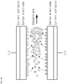
- The CDI method refers to a method of removing an ion (a contaminant) using a principle of adsorbing and desorbing ion at a surface of an electrode by an electrical force. This will be further described with reference to
Figs. 9 and10 . When passing raw water including an ion between the electrodes with power supplied to the electrode, an anion moves to anode and a cation moves to cathode, as illustrated inFig. 9 . In other words, adsorption occurs. By means of the adsorption, the ion included in the raw water may be removed. Meanwhile, when the adsorption continues, the electrode cannot adsorb the ion any longer. Even in this case, as illustrated inFig. 10 , it is necessary to desorb the ions adsorbed in the electrode to regenerate the electrode. To this end, a voltage with an opposite polarity of purified water may be applied. In this case, regeneration water is generated and discharged. - Several documents disclose supplying a disinfectant to a CDI-unit, for instance
JP2009190016 US2005103717 ,CN102786174 . - The inventors of the present invention found the fact that as the CDI-type water treatment device is used, bacteria are formed in a filter (more exactly, in an electrode part which will be described later) and thus a lifespan of the filter is reduced. More specifically, as the CDI-type water treatment device is used, bacteria flow in the filter through raw water or bacteria increase in the filter, thereby forming a lot of bacteria in the filter. When bacteria are formed, a biofilm, etc. is formed, and thereby a pressure drop of the filter increases. This may reduce extract flow of purified water and also deteriorate purification performance by contaminating an electrode surface of the filter. Thus, in order to continuously use the CDI-type water treatment, it is necessary to sterilize the filter. However, an additional introduction of the chemical substance for this may cause problems in lifespan of electrodes, taste and odor, stability, etc.
- The present invention is to solve the above-mentioned problems. The task of the present invention is to provide a method for capacitive deionization of water using a CDI-type water treatment device capable of performing sterilization without the need to additionally supply a chemical substance as a sterilization substance, thereby preventing in advance problems caused by bacteria. Additionally, the task of the present invention is to provide a CDI-type water treatment method where a rejection of a contaminant is not reduced even if the sterilization is performed.
- The invention provides a method as defined in the claims for capacitive deionization of water using a CDI-type water treatment device. The CDI-type water treatment device according to the present invention includes a filter unit for purifying raw water in a CDI type through an electrode part formed by alternately stacking electrodes and separators; and a sterilization unit provided on the front of the filter unit to supply the electrode part with a sterilization substance, which has been generated from the raw water in order to sterilize the electrode part. The sterilization unit, in this case, operates when the electrode part has both stopped purifying raw water and stopped regeneration the electrodes.
- The CDI-type water treatment device reduces chlorine ion (Cl-) in raw water to chlorine (Cl2) to generate the sterilization substance. Thus, the CDI-type water treatment device may perform the sterilization without the need to additionally supply the chemical substance as the sterilization substrate, thereby preventing in advance the problems caused by bacteria. Additionally, since the CDI-type water treatment device provides the sterilization substance to the electrode part when both the water-purifying mode and regeneration mode are not performed, the CDI-type water treatment device may not only inhibit the increase of pressure drop, but mostly maintain the TDS rejection constantly.
-
-
Fig. 1 is a perspective view illustrating a filter unit; -
Fig. 2 is an exploded perspective view illustrating the filter unit ofFig. 1 ; -
Fig. 3 is an exploded perspective view illustrating an electrode part and a terminal part of the filter unit ofFig. 1 ; -
Fig. 4 is a cross-sectional view taken along line A-A of the filter unit ofFig. 1 ; -
Fig. 5 is a schematic view schematically illustrating the water treatment device; -
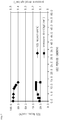
Fig. 6 is a graph showing a TDS rejection and a pressure drop according to the use period of the water treatment device when the electrode part is not sterilized; -
Fig. 7 is a graph showing a TDS rejection and a pressure drop according to the use period of the water treatment device when continuously supplying the sterilization substance to the electrode part regardless of being in the water-purifying mode or regeneration mode; -
Fig. 8 is a graph showing a TDS rejection and a pressure drop according to the use period of the water treatment device when supplying a sterilization substance to the electrode part whenever a predetermined time passed without performing a water-purifying mode and a regeneration mode; -
Fig. 9 is a conceptual diagram explaining a principle of achieving purification in a CDI method; and -
Fig. 10 is a conceptual diagram explaining a principle of achieving regeneration in the CDI method. - Hereinafter, preferable embodiments of the present invention will be explained in detail with reference to the drawings attached. However, the present invention is not limited or restricted by the embodiments below.
-
Fig. 1 is a perspective view illustrating a filter unit,Fig. 2 is an exploded perspective view illustrating the filter unit ofFig. 1 ,Fig. 3 is an exploded perspective view illustrating an electrode part and a terminal part of the filter unit ofFig. 1 , andFig. 4 is a cross-sectional view taken along line A-A of the filter unit ofFig. 1 . The water treatment device relates to a CDI-type water treatment device, which includes afilter unit 100 and asterilization unit 200. - The
filter unit 100 includes anelectrode part 110, afilter case part 130 and aterminal part 150. First of all, theelectrode part 110 will be described. Theelectrode part 110 plays a role of purifying raw water using a CDI method. More specifically, as illustrated inFig. 3 , theelectrode part 110 is formed aselectrodes separator 112 are alternately stacked. In this case, the electrodes include ananode 111 and acathode 113. In other words, theelectrode part 110 is formed as theanode 111 and thecathode 113 are oppositely stacked through theseparator 112. Here, theseparator 112 forms a gap between theanode 111 andcathode 113. - In general, however, the
electrodes Fig. 3 ), andprotrusion portions protrusion portions electrodes electrode part 110 may be operated by supplying power (or voltage or current) to theelectrodes electrode tabs - Meanwhile, it is necessary to electrically separate the
anode 111 andcathode 113. Thus, as illustrated inFig. 3 , it is preferable that ananode tap 111a and acathode tap 113a are separated from each other. However, as illustrated inFig. 3 , it is preferable that theanode tap 111 is protruded in the same direction at the same position with theanode tap 111, and that thecathode tap 113a is protruded in the same direction at the same position with thecathode tap 113a. Then, it is convenient to supply power to theanode tap 111a andcathode tap 113a, respectively. - Next, a
filter case part 130 will be described. As illustrated inFig. 2 , thefilter case part 130 accommodates theelectrode part 110. More specifically, anopening 132 is formed at the top of thefilter case part 130, and the filter case part includes alower case 131 in which theelectrode part 110 is accommodated and anupper case 136 sealing theopening 132 of thelower case 131. In other words, theelectrode part 110 is inserted into the inside of thelower case 131 through theopening 132 of thelower case 131, and then theopening 132 of thelower case 131 is sealed with theupper case 136. Here, thelower case 131 has aninlet 133 on its side into which raw water enters, and theupper case 136 has anoutlet 137 on its top from which purified water exits. In this case, theoutlet 137 is formed to correspond to anoutlet hole 115 of theelectrode part 110. - According to the structure above, raw water is purified by the following process: First, raw water is supplied to the inside of the
filter case part 130 through theinlet 133. Next, by the pressure resulting from this supplying, the raw water enters into the inside of theelectrode part 110 through the side surface of theelectrode part 110. The raw water then flows between theanode 111 andcathode 113 inside theelectrode part 110 to be purified according to the CDI method. Then, the raw water (that is, purified water) is discharged to the outside of theelectrode part 110 through anoutlet hole 115. Then, the raw water is discharged to the outside of thefilter case part 130 through theoutlet 137. - Next, a
terminal part 150 will be described. Theterminal part 150 is electrically connected to the electrode taps 111a and 113a to supply power from external power (not illustrated) to theelectrodes Figs. 2 and3 , theterminal part 150 includes aconductive electrode terminal 151 contacting with the electrodes taps 111a and 113a at one end. (When supplying power to the other end of the electrode terminal with the electrodes taps contacting with one end of the electrode end, power may be supplied to the electrode taps through the electrode terminal.) - It is preferable that the
electrode terminal 151 is made of stainless steel. This also applies to aterminal band 152 which will be described later. This is because stainless steel is inexpensive and has good electrical conductivity. However, stainless steel has a limitation that the stainless steel becomes oxidized according to the current flow and thus rust may occur. In order to solve this limitation, it may be considered to form theelectrode terminal 151 with titanium (Ti). However, since titanium may be oxidized according to the current flow, electrical conductivity may be weakened. - Accordingly, it is most preferable to form the
electrode terminal 151 with platinum (Pt). This also applies to theterminal band 152 which will be described later. This is because platinum does not have problems that platinum is oxidized and thus rust occurs, or electrical conductivity is weakened. Meanwhile, considering that platinum is expensive, it may be considered to form theelectrode terminal 151 by coating platinum on the surface. - However, the
terminal part 150 may include a conductiveterminal band 152 enclosing theelectrode tap electrode terminal 151. In this case, it is preferable that theterminal band 152 encloses the electrode taps 111a and 113a along with theelectrode terminal 151 so that the electrode taps 111a and 113a could be compressed inwardly. In addition, it is preferable that theterminal band 152 encloses the electrode taps 111a and 113a at least one round along with theelectrode terminal 151 from the outside of the electrode taps 111a and 113a. - A
sterilization unit 200 plays a role of generating a sterilization substance from raw water to supply the sterilization substance to theelectrode part 110 in order to sterilize theelectrode part 110. In order to generate the sterilization substance, thesterilization unit 200 reduces chlorine ion (Cl-) in raw water to chlorine (Cl2). In order to reduce the chlorine ion to chlorine, thesterilization unit 200 includes a sterilization terminal part (not illustrated) coated with ruthenium oxide (RuOx), and asterilization case part 210 accommodating the sterilization terminal part. A description thereof will be further described below. - When power (or current or voltage) is applied to the sterilization terminal part, chlorine ion in raw water may be reduced to chlorine by ruthenium oxide of the sterilization terminal part (raw water generally includes chlorine ion by itself). Ruthenium oxide serves as a catalyst decreasing potential difference when reducing chlorine ion to chlorine. The chlorine thus generated may melt right away in raw water and could be hypochlorous acid (HOCl). HOCl is a sterilization substance capable of sterilizing bacteria and is a mixed oxidant. This
sterilization unit 200 reduces chlorine ion in raw water to generate the sterilization substance. - Accordingly, the water treatment device according to the present embodiment sterilizes the
electrode part 110 without the need to further supply a chemical substance as the sterilization substance. Additionally, the water treatment device according to the present embodiment prevents in advance problems which occur due to bacteria through the sterilization so that the device may be semi-permanently used. - The sterilization terminal part may be prepared as below. First, ruthenium is coated on a metal terminal such as the
electrode terminal 151. Next, the metal terminal is heated at a high temperature. By means of the heating, ruthenium may be oxidized to ruthenium oxide. Accordingly, ruthenium oxide mostly exists on the surface of the metal terminal. - However, as illustrated in
Fig. 5 which will be mentioned later, thesterilization unit 200 is located at the front of thefilter unit 100. When thesterilization unit 200 is prepared as above, thesterilization unit 200 may be independently operated regardless of thefilter unit 100. Accordingly, when operating thesterilization unit 200, raw water including the sterilization substance may be supplied to theelectrode part 110, and when stopping thesterilization unit 200, raw water which does not include the sterilization substance may be supplied to theelectrode part 110. As such, when operating thesterilization unit 200 selectively, a lifespan of the sterilization terminal part may be extended. Additionally, when operating thesterilization unit 200 independently, the problems caused by bacteria such as the increase of pressure drop may be solved and also the TDS (Total Dissolved Solids) rejection may be maintained. - The water treatment device according to the present embodiment may be in a water-purifying mode, a regeneration mode and a sterilization mode. The water-purifying mode is a mode which purifies raw water in the
electrode part 110, the regeneration mode is a mode which regenerateselectrodes electrode part 110, and the sterilization mode is a mode which sterilizes bacteria in theelectrode part 110 through thesterilization unit 200. The water treatment device according to present embodiment includes a control unit (not illustrated) which controls power supplied to the sterilization terminal part in order to operate the sterilization mode. - The control unit performs a control of supplying power to the sterilization terminal part when in the sterilization mode among the water-purifying mode, regeneration mode and sterilization mode. Inventors of the present invention found the fact that when supplying the sterilization substance such as HOCl to the
filter unit 100 during the operation offilter unit 100 such as in water-purifying mode or regeneration mode, iron oxide (FeOx), etc. may occur, thereby reducing the TDS rejection of thefilter unit 100. Since iron oxide has a small particle size, iron oxide may be jammed in a gap and thus may not be properly discharged from the electrode. When iron oxide is not discharged, it is difficult for the electrodes to be regenerated properly. Thus, the sterilization mode is performed when both the water-purifying mode and regeneration mode are not performed. - Meanwhile, when frequently performing the sterilization mode, power may be wasted or a lifespan of the sterilization terminal part may be reduced. The sterilization mode is performed after a predetermined time (preferably about 4 hours) passed with the water-purifying mode and regeneration mode not performed. In this case, the predetermined time may be properly selected according to the time that bacteria increase in the
electrode part 110. - Meanwhile, it is preferable that the control unit determines the strength of power to be supplied to the sterilization terminal part in the sterilization mode according to the TDS of raw water. When the TDS of raw water is high, this means that the concentration of chlorine ion in raw water could be high. Thus, when the TDS of raw water is high, it is preferable to reduce the strength of power to be supplied to the sterilization terminal part in the sterilization mode. Even if the strength of power is low, since the concentration of chlorine ion in raw water is high, the sterilization substance may be fully generated. In comparison, when the TDS of raw water is low, it is preferable to enlarge the strength of power to be supplied to the sterilization terminal part in the sterilization mode. Here, the TDS of raw water may be estimated by installing an additional TDS sensor at the front of the
filter case part 130. - However, when the control is made so that a certain voltage is applied to the
electrodes electrodes electrodes electrodes electrodes electrodes -
Fig. 5 is a schematic view schematically illustrating the water treatment device. As illustrated inFig. 5 , the water treatment device not only includes afilter unit 100, asterilization unit 200, a control unit, but includes asupply unit 310 which supplies raw water to thefilter unit 100, apurge unit 320 which purges purified water to the user, adischarge unit 330 which discharges regeneration water to the outside, and a valve unit. - Here, the
supply unit 310 may be implemented in various ways. As an example, thesupply unit 310 may be a conduit to receive raw water from the outside. Additionally, thepurge unit 320 may be implemented in various ways. As an example, thepurge unit 320 may be a cock for selectively supplying purified water to the user. Also, thedischarge unit 330 may be implemented in various ways. As an example, thedischarge unit 330 may be a conduit to discharge regeneration water to the outside. - In addition, the valve unit may include a
supply valve 341 installed on a flow path passing from thesupply unit 310 to aninlet 133; a purge valve 342 installed on a flow path passing from anoutlet 137 to thepurge unit 320; a discharge valve 343 installed on a flow path passing from theoutlet 137 to thedischarge unit 330; a washing valve 344 installed on a flow path passing from the front of thesupply valve 341 to theoutlet 137; and adrain valve 345 installed on a flow path passing from the rear of thesupply valve 341 to the outside. Valves of the valve unit may be implemented as a solenoid valve for electronic control. For reference, the front of thesupply valve 341 means a left side of thesupply valve 341 based onFig. 5 , and the bottom of thesupply valve 341 means a right side of thesupply valve 341 based onFig. 5 . - However, as illustrated in
Fig. 5 , thefilter unit 100 may include twoelectrode parts electrode parts filter unit 100 includes twoelectrode parts Fig. 5 , thepurge valves discharge valves washing valves - Here, it is preferable that raw water is selectively supplied to the
inlet outlet sterilization case part 210, since it is more advantageous in sterilizing theelectrode parts electrode parts outlet hole 115 of theelectrode parts Fig. 4 ). - Hereinafter, the control of valves by the control unit will be described. First, the water-purifying mode will be explained. When a
first electrode part 110a is in the water-purifying mode, only thesupply valve 341 and purgevalve 342a are open. The rest of valves of the valve unit are closed. In case of such opening and closing, raw water may be supplied to the user through thepurge unit 320 after being purified through thefirst electrode part 110a. - When a
second electrode part 110b is in the water-purifying mode, only thesupply valve 341 andpurge valve 342b are open. In other words, this is the same as the case where the first electrode part is in the water-purifying mode. In case of such opening and closing, the raw water may be supplied to the user through thepurge unit 320 after being purified through thesecond electrode part 110b. In this case, for water purification, it is necessary for the control unit to supply power to the electrode terminal of thefirst electrode part 110a or the electrode terminal of thesecond electrode part 110b. However, as mentioned above, it is not necessary to supply power to the sterilization terminal part in the water-purifying mode. This also applies to the regeneration mode which will be described later. - Next, the regeneration mode will be explained. When the
first electrode part 110a is in the regeneration mode, only thesupply valve 341 anddischarge valve 343a are open. The rest will be closed. In case of such opening and closing, the raw water may be discharged to the outside through thedischarge unit 330 by passing thefirst electrode part 110a. When thesecond electrode part 110b is in the regeneration mode, only thesupply valve 341 anddischarge valve 343b are open. That is, this is the same as the case where the first electrode part is in the regeneration mode. In case of such opening and closing, the raw water may be discharged to the outside through thedischarge unit 330 by passing thesecond electrode part 110b. In this case, for the regeneration, it is necessary for the control unit to supply power to the electrode terminal of thefirst electrode part 110a or the electrode terminal of thesecond electrode part 110b. - In this case, the water-purifying mode and regeneration mode may be performed in a complex way. For example, when the
first electrode part 110a is in the water-purifying mode and thesecond electrode part 110b is in the regeneration mode, only thesupply valve 341,purge valve 342a anddischarge valve 343b are open. - Next, the back washing in the sterilization mode will be explained. When back-washing the
first electrode part 110a, only thewashing valve 344a anddrain valve 345 are open. The rest will be closed. In case of such opening and closing, the raw water may enter into thefirst electrode part 110a through theoutlet 137a of the firstfilter case part 130a and be discharged to the outside through theinlet 133a of the firstfilter case part 130a. In this case, the raw water may be immediately discharged to the outside, and may be discharged to the outside through thedischarge unit 330 as illustrated inFig. 5 (the direction that the raw water flows in the back washing is opposite to the direction that the raw water flows in the water-purifying mode or in the regeneration mode. Thus, "back" is added to "washing"). - When back-washing the
second electrode part 110b, only thewashing valve 344b anddrain valve 345 are open. That is, this is the same as the case where thefirst electrode part 110a is back-washed. In case of such opening and closing, the raw water may enter into thesecond electrode part 110b through theoutlet 137b of the secondfilter case part 130b and then be drained to the outside through theinlet 133b of the secondfilter case part 130b. In this case, the control unit may supply power to the sterilization terminal part during the back washing for the sterilization of thefirst electrode part 110a or thesecond electrode part 110b. - Alternatively, the normal washing and back washing may be interchangeably used as follows: First, only the
washing valve 344a anddischarge valve 343b are open. The rest will be closed. In case of such opening and closing, the raw water may be discharged to the outside by going through theoutlet 137a of the firstfilter case part 130a → thefirst electrode part 110a → theinlet 133a of the firstfilter case part 130a → theinlet 133b of the secondfilter case part 130b → thesecond electrode part 110b → theoutlet 137b of the secondfilter case part 130b. In this case, the control unit may supply power to the sterilization terminal part for sterilization. - As another alternative, only the
washing valve 344b anddischarge valve 343a are open. In case of such opening and closing, the raw water may be discharged to the outside by going through theoutlet 137b of the secondfilter case part 130b → thesecond electrode part 110b → theinlet 133b of the secondfilter case part 130b → theinlet 133a of the firstfilter case part 130a → thefirst electrode part 110a → theoutlet 137a of the firstfilter case part 130a. In this case, the control unit may supply power to the sterilization terminal part for sterilization. - Next, the reverse sterilization (second sterilization) in the sterilization mode will be explained. When reverse-sterilizing the
first electrode part 110a, only thewashing valve 344a anddrain valve 345 are open. The rest will be closed. In case of such opening and closing, the raw water may enter into thefirst electrode part 110a through theoutlet 137a of the firstfilter case part 130a, and then be discharged to the outside through theinlet 133a of the firstfilter case part 130a. In this case, the raw water may be immediately discharged to the outside, and may be discharged to the outside through thedischarge unit 330 as illustrated inFig. 5 (the direction that the raw water flows in the reverse sterilization is opposite to the direction that the raw water flows in the water-purifying mode or in the regeneration mode. Thus, "reverse" is added to "sterilization"). - When reverse-sterilizing the
second electrode part 110b, only thewashing valve 344b anddrain valve 345 are open. That is, this is the same as the case where thefirst electrode part 110a is reversely sterilized. In case of such opening and closing, the raw water may enter into thesecond electrode part 110b through theoutlet 137b of the secondfilter case part 130b, and then be drained to the outside through theinlet 133b of the secondfilter case part 130b. In this case, it is necessary for the control unit to supply power to the sterilization terminal part during the reverse sterilization for the sterilization of thefirst electrode part 110a orsecond electrode part 110b. - Finally, the normal sterilization (first sterilization) in the sterilization mode will be explained. When normally sterilizing the
first electrode part 110a, only thesupply valve 341 anddischarge valve 343a are open. The rest will be closed. In case of such opening and closing, the raw material may enter into thefirst electrode part 110a through theinlet 133a of the firstfilter case part 130a, and then be discharged to the outside through theoutlet 137a of the firstfilter case part 130a (for comparison with the reverse sterilization, the first sterilization will be referred to as normal sterilization). - When normally sterilizing the
second electrode part 110b, only thesupply valve 341 anddischarge valve 343b are open. That is, this is the same as the case where thefirst electrode part 110a is normally sterilized. In case of such opening and closing, the raw water may enter into thesecond electrode part 110b through theinlet 133b of the secondfilter case part 130b and then be discharged to the outside through theoutlet 137b of the secondfilter case part 130b. In this case, it is necessary for the control unit to supply power to the sterilization terminal part during the normal sterilization for the sterilization of thefirst electrode part 110a or thesecond electrode part 110b. For reference, considering the flow of raw water, the normal sterilization is suitable for the sterilization at theinlet 137 in theelectrode part 110, and the reverse sterilization is suitable for the sterilization at theoutlet 137 of theelectrode part 110. - Here, it is preferable that the back washing, reverse sterilization and normal sterilization during the sterilization mode are performed in a complex way. In this case, it is preferable that the normal sterilization is performed after the reverse sterilization. Compared to the case where purified water is generated as the water-purifying mode is performed after the normal sterilization, the case where purified water is generated as the water-purifying mode is performed after the reverse sterilization is highly likely to have the residue sterilization substance included in purified water and supplied to the user (the sterilization substance at entry may pass the CDI-type electrode part and then be removed). It is preferable that the normal sterilization is performed last. Additionally, considering the object of the back washing (to remove particulate materials which will be mentioned later), it is preferable that the back washing is performed before the reverse sterilization or normal sterilization.
- However, it is preferable that discharge flow (corresponding to a first flow where the raw water is supplied to the inlet during the normal sterilization) discharged to the outside through the
discharge unit 330 during the normal sterilization or the discharge flow (corresponding to a second flow where the raw water is supplied to the outlet during the reverse sterilization) discharged to the outside through thedischarge unit 330 during the reverse sterilization is smaller than the discharge flow (corresponding to a third flow where the raw water is supplied to the outlet during the back washing) discharged to the outside through thedischarge unit 330 during the back washing. - This will be described in detail. In the
electrode part 110, a particulate material stays more in theinlet 133 than in theoutlet 137. Thus, in order to remove the material, it is preferable to allow the raw water to strongly flow from theoutlet 137 to the inlet 133 (seeFig. 4 ). Accordingly, considering that a basic role of the back washing is to remove the particulate material, it is preferable that the discharge flow during the back washing is high. - However, the amount of sterilization substance generated in the
sterilization unit 200 is limited. Thus, as the flow increases, the concentration of sterilization substance reduces, and thereby a sterilization effect cannot help being reduced. Accordingly, considering that a basic role of the normal sterilization or reverse sterilization is to sterilize the electrode part, it is preferable that the discharge flow in the normal sterilization or reverse sterilization is relatively low. For reference, the discharge flow of the normal sterilization may be the same as the discharge amount of the reverse sterilization. Here, the discharge flow may be controlled through a diameter of a pipe. As an example, when a pipe diameter after the discharge valve 343 ordrain valve 345 is smaller than a pipe diameter after the purge valve 342, the discharge flow may be small. - Meanwhile, when the
filter unit 100 includes twoelectrode parts flow 346 at the bottom of the discharge valve 343. Here, the valve for controllingflow 346 may control the amount of regeneration water discharged to the outside to control the rate between purified water and regeneration water. - As an example, when the
first electrode part 110a is in the water-purifying mode and thesecond electrode part 110b is in the regeneration mode, only thepurge valve 342a anddischarge valve 343b will be open. The rest will be closed. In this case, it is assumed that raw water is supplied from thesupply unit 310 to thefilter unit 100 in an amount of 10. When the valve for controllingflow 346 is controlled so that regeneration water could be discharged from thesecond electrode part 110b to the outside in an amount of 2, raw water will be supplied from thesupply unit 310 to thefirst electrode part 110a in an amount of 8. - For reference, the water treatment device according to the present embodiment may further include another filter in addition to the
filter unit 100. As an example, the water treatment device according to the present embodiment may further include apre-carbon filter 401 for mainly removing chlorine substance, or apost-carbon filter 402 for mainly removing smell, as illustrated inFig. 5 . -
Fig. 6 is a graph illustrating a TDS rejection and a pressure drop according to the use period of the water treatment device in case of not sterilizing the electrode mode. When the electrode part is not sterilized, as illustrated inFig. 6 , bacteria may increase in theelectrode part 110, which may lead to the increase in the pressure drop (a pressure difference between the outlet and inlet). Accordingly, a lifespan of the filter may be reduced. -
Fig. 7 is a graph illustrating a TDS rejection and a pressure drop according to the use period of the water treatment device when the sterilization substance is continuously supplied to the electrode part regardless of being in the water-purifying mode or regeneration mode. When continuously supplying the sterilization substance to theelectrode part 110 regardless of being in the water-purifying mode or regeneration mode, as illustrated inFig. 7 , the increase in pressure drop may be inhibited. However, the TDS rejection (i.e., contaminant rejection) may be reduced. As explained above, this is caused by the occurrence of inorganic ion such as iron oxide. Meanwhile, even if the TDS rejection is reduced, since the increase in the pressure drop may be inhibited, the supply of the sterilization substance is meaningful. -
Fig. 8 is a graph illustrating a TDS rejection and a pressure drop according to the use period of the water treatment device when supplying the sterilization substance to the electrode part whenever a predetermined time passes with the water-purifying mode and regeneration mode not performed. When supplying the sterilization mode to the electrode mode whenever a predetermined time passes with the water-purifying mode and the regeneration mode not performed, as illustrated inFig. 8 , the increase in pressure drop may be inhibited, and also the TDS rejection may be constantly maintained.
Claims (13)
- A method for capacitive deionization of water using a capacitive deionization type (CDI-type) water treatment device, comprising a capacitive deionization unit (100) for purifying raw water comprising an electrode part (110) formed by alternately stacking electrodes (111,113) and separators (112), wherein the capacitive deionization unit (100) has an inlet (133) to which the raw water is supplied, an outlet (137) from which the purified water or the regeneration water is discharged, and a filter case part (130) accommodating the electrode part (110); a sterilization unit (200) provided on the front of the capacitive deionization unit (100), wherein the sterilization unit (200) comprises a sterilization case part (210) accommodating a sterilization terminal part coated with ruthenium oxide (RuOx); and a control unit configured to control power supplied to the sterilization terminal part; the method comprising:using the sterilization unit (200), reducing chlorine ions (Cl-) in the raw water to chlorine (Ch) in order to generate a sterilization substance in the raw water,in a water-purifying mode, purifying raw water at the electrode part (110), and discharging purified water, andin a regeneration mode for regenerating an electrode of the electrode part (110), discharging regeneration water; andamong the water-purifying mode, the regeneration mode, and a sterilization mode for sterilizing bacteria in the electrode part (110) by using the sterilization unit (200), performing by the control unit a control of supplying power to the sterilization terminal part when in the sterilization mode after a predetermined time passes with the water-purifying mode and the regeneration mode not performed.
- The method of claim 1, comprising, by the control unit, controlling a strength of power to be supplied to the sterilization terminal part in the sterilization mode according to total dissolved solids (TDS) of the raw water.
- The method of claim 1, comprising, by the control unit, controlling a strength of power to be supplied to the sterilization terminal part in the sterilization mode according to a strength of current flowing in the electrode part (110) when a certain voltage is applied to the electrode part (110) in the water-purifying mode.
- The method of claim 1, comprising receiving at the inlet (133) raw water through the sterilization unit (200) by a first flow rate during the operation of the sterilization unit (200) for a first sterilization for the electrode part (110).
- The method of claim 4, comprising receiving at the outlet (137) the raw water through the sterilization unit (200) by a second flow rate during the operation of the sterilization unit (200) for a second sterilization for the electrode part (110).
- The method of claim 4 or 5, comprising receiving at the outlet (137) the raw water through the sterilization unit (200) by a third flow rate, which is greater than the first flow rate or the second flow rate, for back washing of the electrode part (110).
- The method of claim 1, wherein the device further comprises:
a supply unit (310) configured to supply the raw water to the capacitive deionization unit (100); a purge unit (320) configured to purge the purified water to a user; a discharge unit (330) configured to discharge the regeneration water to the outside; and a valve unit including a supply valve (341) installed on a flow path passing from the supply unit (310) to the inlet (133); a purge valve (342) installed on a flow path passing from the outlet (137) to the purge unit (320); a discharge valve (343) installed on a flow path passing from the outlet (137) to the discharge unit (330); a washing valve (344) installed on a flow path passing from a front of the supply valve (341) to the outlet (137); and a drain valve (345) installed on a flow path passing from a rear of the supply valve (341) to the outside; the method comprising,
by the control unit, controlling an opening and closing of the valves. - The method of claim 7, comprising by the control unit performing a control of opening the supply valve (341), closing the discharge valve (343), opening the purge valve (342), closing the washing valve (344), and closing the drain valve (345), during non-operation of the sterilization unit (200) in the water-purifying mode.
- The method of claim 7, comprising, by the control unit performing a control of opening the supply valve (341), opening the discharge valve (343), closing the purge valve (342), closing the washing valve (344), and closing the drain valve (345), during non-operation of the sterilization unit (200) in the regeneration mode.
- The method of claim 7, comprising, by the control unit performing a control of opening the supply valve (341), opening the discharge valve (343), closing the purge valve (342), closing the washing valve (344), and closing the drain valve (345), during operation of the sterilization unit (200) for a first sterilization for the electrode part (110) in the sterilization mode.
- The method of claim 10, comprising, by the control unit performing a control of closing the supply valve (341), closing the discharge valve (343), closing the purge valve (342), opening the washing valve (344), and opening the drain valve (345), during operation of the sterilization unit (200) for a second sterilization for the electrode part (110) in the sterilization mode.
- The method of claim 10 or 11, comprising, by the control unit performing a control of closing the supply valve (341), closing the discharge valve (343), closing the purge valve (342), opening the washing valve (344), and opening the drain valve (345) for back washing of the electrode part (110) in the sterilization mode.
- The method of any of claims 1 to 12, in which the predetermined time is 4 hours.
Applications Claiming Priority (2)
| Application Number | Priority Date | Filing Date | Title |
|---|---|---|---|
| KR1020130161066A KR101897567B1 (en) | 2013-12-23 | 2013-12-23 | Cdi type water treatment apparatus |
| PCT/KR2014/012059 WO2015099320A1 (en) | 2013-12-23 | 2014-12-09 | Cdi-type water treatment device |
Publications (3)
| Publication Number | Publication Date |
|---|---|
| EP3088366A1 EP3088366A1 (en) | 2016-11-02 |
| EP3088366A4 EP3088366A4 (en) | 2016-11-23 |
| EP3088366B1 true EP3088366B1 (en) | 2021-11-10 |
Family
ID=53479122
Family Applications (1)
| Application Number | Title | Priority Date | Filing Date |
|---|---|---|---|
| EP14875126.6A Active EP3088366B1 (en) | 2013-12-23 | 2014-12-09 | Method for water treatment using a capacitive deionization device |
Country Status (6)
| Country | Link |
|---|---|
| US (1) | US11084740B2 (en) |
| EP (1) | EP3088366B1 (en) |
| JP (1) | JP6543630B2 (en) |
| KR (1) | KR101897567B1 (en) |
| CN (1) | CN105849050B (en) |
| WO (1) | WO2015099320A1 (en) |
Families Citing this family (10)
| Publication number | Priority date | Publication date | Assignee | Title |
|---|---|---|---|---|
| US10968117B2 (en) * | 2015-04-14 | 2021-04-06 | Koninklijke Philips N.V. | Electrosorption purification system with recirculation |
| GB201603889D0 (en) * | 2016-03-07 | 2016-04-20 | Fujifilm Mfg Europe Bv | Capacitive deionisation |
| CN106830227A (en) * | 2017-03-01 | 2017-06-13 | 河海大学 | The membrane capacitance deionizer and processing method of a kind of circular treatment |
| US20200378649A1 (en) * | 2017-12-28 | 2020-12-03 | Kyungdong Navien Co., Ltd. | Hot-water mat and sterilization module |
| US12623933B2 (en) | 2019-03-07 | 2026-05-12 | Kyungdong Navien Co., Ltd | Water-softening system |
| US11572287B2 (en) * | 2019-03-07 | 2023-02-07 | Kyungdong Navien Co., Ltd. | Water-softening system |
| KR102557399B1 (en) * | 2019-03-07 | 2023-07-20 | 주식회사 경동나비엔 | Water softening system |
| CN113880201A (en) * | 2020-07-03 | 2022-01-04 | 拓狄克科技(江苏)有限公司 | Water purifying device |
| EP4029835B1 (en) * | 2021-01-13 | 2023-08-09 | Robert Bosch GmbH | Device for deionising water |
| KR102514234B1 (en) * | 2022-02-14 | 2023-03-27 | 케이에스티 주식회사 | Electrode ion exchange maximizer |
Family Cites Families (26)
| Publication number | Priority date | Publication date | Assignee | Title |
|---|---|---|---|---|
| ID18692A (en) | 1996-11-05 | 1998-04-30 | Sanden Corp | INSTALLATION OF CLEANING WATER WITH THE FUNCTION TO GENERATE CHLORINE WITH THE FUNCTION OF BACTERIAL DISORDERS |
| CN1188744A (en) * | 1996-11-05 | 1998-07-29 | 三电有限公司 | Water purification system having chlorine generating function in addition to bacteriostatic function |
| JPH1190129A (en) * | 1997-09-24 | 1999-04-06 | Matsushita Electric Works Ltd | Bathtub water circulation purification device |
| JP4090640B2 (en) * | 1999-09-03 | 2008-05-28 | オルガノ株式会社 | Liquid passing method and apparatus for liquid passing capacitor |
| US6580598B2 (en) | 2001-02-15 | 2003-06-17 | Luxon Energy Devices Corporation | Deionizers with energy recovery |
| EP1291324A3 (en) | 2001-09-07 | 2003-10-29 | Luxon Energy Devices Corporation | Deionizers with energy recovery |
| JP2003285066A (en) * | 2002-03-27 | 2003-10-07 | Luxon Energy Devices Corp | Pure water apparatus with energy recovery |
| JP2005087898A (en) * | 2003-09-18 | 2005-04-07 | Air Water Inc | Electrostatic deionization apparatus and electrostatic deionization method |
| US20050103717A1 (en) * | 2003-11-13 | 2005-05-19 | United States Filter Corporation | Water treatment system and method |
| KR100894558B1 (en) * | 2007-07-31 | 2009-04-24 | 권오정 | Cold and hot water ionizer |
| JP2009190016A (en) * | 2008-02-13 | 2009-08-27 | Linxross Inc | Method for preventing and removing biofilm in electrolytic capacitor for water purification |
| KR100973669B1 (en) * | 2009-11-27 | 2010-08-04 | 제이에이건설주식회사 | Clean water treating system of small scale waterworks using capacitive deionization |
| EP2571594B1 (en) * | 2010-05-19 | 2020-02-19 | Woongjin Coway Co., Ltd. | Water treatment apparatus and sterilizing and cleansing method thereof |
| KR101220891B1 (en) | 2010-06-30 | 2013-01-11 | 문상봉 | A porous 3-dimensional bipolar electrode, an electrolyzer having the porous 3-dimensional bipolar electrode, and water treatment method using the electrolyzer having the porous 3-dimensional bipolar electrode |
| DK3257819T3 (en) * | 2010-08-06 | 2020-01-13 | De Nora Holdings Us Inc | Electrolytic on-site generator |
| JP4734664B1 (en) * | 2010-09-17 | 2011-07-27 | 田中貴金属工業株式会社 | Electrode for electrolysis, anode for electrolysis of ozone, anode for electrolysis of persulfate, and anode for chromium electrooxidation |
| WO2012091500A2 (en) * | 2010-12-30 | 2012-07-05 | Woongjin Coway Co., Ltd | Water treatment apparatus and water treatment method using the same |
| KR101675749B1 (en) * | 2010-12-30 | 2016-11-16 | 코웨이 주식회사 | Water purifier and water-treating method using the same |
| MY175377A (en) | 2011-06-02 | 2020-06-23 | Coway Co Ltd | Sterilizing apparatus and method for water treatment apparatus |
| KR101876214B1 (en) | 2011-06-07 | 2018-07-10 | 코웨이 주식회사 | Water treatment apparatus and sterilizing method thereof |
| SG10201605359TA (en) * | 2011-07-01 | 2016-08-30 | Evoqua Water Technologies Pte Ltd | Electrodesalination system and method |
| US9174859B2 (en) * | 2011-11-24 | 2015-11-03 | Eco Watertech, Inc. | Method for treating waste waters |
| KR102010978B1 (en) | 2011-12-29 | 2019-08-14 | 웅진코웨이 주식회사 | Apparatus for water treatment using capacitive deionization and method for controlling the same |
| KR20130096521A (en) | 2012-02-22 | 2013-08-30 | 코웨이 주식회사 | Water treatment apparatus, cleansing device, and method for cleansing water treatment apparatus by using wireless communications |
| KR101406986B1 (en) * | 2012-03-23 | 2014-06-13 | (주) 시온텍 | Apparatus and method of producing electrolytic disinfection water |
| CN102786174B (en) * | 2012-03-29 | 2013-12-18 | 波鹰(厦门)科技有限公司 | Seawater desalination device and method thereof |
-
2013
- 2013-12-23 KR KR1020130161066A patent/KR101897567B1/en active Active
-
2014
- 2014-12-09 US US15/103,199 patent/US11084740B2/en active Active
- 2014-12-09 JP JP2016542684A patent/JP6543630B2/en active Active
- 2014-12-09 EP EP14875126.6A patent/EP3088366B1/en active Active
- 2014-12-09 WO PCT/KR2014/012059 patent/WO2015099320A1/en not_active Ceased
- 2014-12-09 CN CN201480070459.7A patent/CN105849050B/en active Active
Non-Patent Citations (1)
| Title |
|---|
| None * |
Also Published As
| Publication number | Publication date |
|---|---|
| CN105849050B (en) | 2019-06-14 |
| EP3088366A1 (en) | 2016-11-02 |
| US20160355418A1 (en) | 2016-12-08 |
| KR20150074245A (en) | 2015-07-02 |
| KR101897567B1 (en) | 2018-09-13 |
| US11084740B2 (en) | 2021-08-10 |
| JP6543630B2 (en) | 2019-07-10 |
| JP2017500201A (en) | 2017-01-05 |
| WO2015099320A1 (en) | 2015-07-02 |
| EP3088366A4 (en) | 2016-11-23 |
| CN105849050A (en) | 2016-08-10 |
Similar Documents
| Publication | Publication Date | Title |
|---|---|---|
| US11084740B2 (en) | CDI-type water treatment method | |
| EP3081537A1 (en) | Device for treating water by cdi method | |
| KR102211119B1 (en) | Cdi type water treatment apparatus | |
| KR101675749B1 (en) | Water purifier and water-treating method using the same | |
| EP3778497B1 (en) | Water treatment device and water treatment method | |
| CN102933277A (en) | Water treatment apparatus and sterilizing and cleansing method thereof | |
| EP3081536A1 (en) | Device for treating water by cdi method | |
| KR100621937B1 (en) | Water purifying apparatus having function of electrolytic disinfection and its disinfection method | |
| JP2006043610A (en) | Electrolytic hydrogen-containing water producing apparatus | |
| KR102220165B1 (en) | Electro deionization-type water treatment apparatus | |
| JP7305742B2 (en) | Faradic porous cell | |
| KR102210190B1 (en) | Cdi type water treatment apparatus and method for controlling the same | |
| KR100988465B1 (en) | Water Purifier with Electrosterilization Function | |
| KR101586302B1 (en) | Water ionizer | |
| KR102054288B1 (en) | Electro deionization type water sterilizing purifier and Sterilizing method for electro deionization type water purifier | |
| EP3527537A1 (en) | Water softening apparatus | |
| US10040706B2 (en) | CDI type water treatment apparatus |
Legal Events
| Date | Code | Title | Description |
|---|---|---|---|
| PUAI | Public reference made under article 153(3) epc to a published international application that has entered the european phase |
Free format text: ORIGINAL CODE: 0009012 |
|
| 17P | Request for examination filed |
Effective date: 20160615 |
|
| AK | Designated contracting states |
Kind code of ref document: A1 Designated state(s): AL AT BE BG CH CY CZ DE DK EE ES FI FR GB GR HR HU IE IS IT LI LT LU LV MC MK MT NL NO PL PT RO RS SE SI SK SM TR |
|
| AX | Request for extension of the european patent |
Extension state: BA ME |
|
| A4 | Supplementary search report drawn up and despatched |
Effective date: 20161025 |
|
| RIC1 | Information provided on ipc code assigned before grant |
Ipc: C02F 1/467 20060101ALI20161019BHEP Ipc: C02F 1/469 20060101AFI20161019BHEP |
|
| DAX | Request for extension of the european patent (deleted) | ||
| STAA | Information on the status of an ep patent application or granted ep patent |
Free format text: STATUS: EXAMINATION IS IN PROGRESS |
|
| 17Q | First examination report despatched |
Effective date: 20170816 |
|
| GRAP | Despatch of communication of intention to grant a patent |
Free format text: ORIGINAL CODE: EPIDOSNIGR1 |
|
| STAA | Information on the status of an ep patent application or granted ep patent |
Free format text: STATUS: GRANT OF PATENT IS INTENDED |
|
| INTG | Intention to grant announced |
Effective date: 20210602 |
|
| GRAS | Grant fee paid |
Free format text: ORIGINAL CODE: EPIDOSNIGR3 |
|
| GRAA | (expected) grant |
Free format text: ORIGINAL CODE: 0009210 |
|
| STAA | Information on the status of an ep patent application or granted ep patent |
Free format text: STATUS: THE PATENT HAS BEEN GRANTED |
|
| AK | Designated contracting states |
Kind code of ref document: B1 Designated state(s): AL AT BE BG CH CY CZ DE DK EE ES FI FR GB GR HR HU IE IS IT LI LT LU LV MC MK MT NL NO PL PT RO RS SE SI SK SM TR |
|
| REG | Reference to a national code |
Ref country code: GB Ref legal event code: FG4D |
|
| REG | Reference to a national code |
Ref country code: AT Ref legal event code: REF Ref document number: 1445949 Country of ref document: AT Kind code of ref document: T Effective date: 20211115 Ref country code: CH Ref legal event code: EP |
|
| REG | Reference to a national code |
Ref country code: DE Ref legal event code: R096 Ref document number: 602014081230 Country of ref document: DE |
|
| REG | Reference to a national code |
Ref country code: IE Ref legal event code: FG4D |
|
| REG | Reference to a national code |
Ref country code: LT Ref legal event code: MG9D |
|
| REG | Reference to a national code |
Ref country code: NL Ref legal event code: MP Effective date: 20211110 |
|
| REG | Reference to a national code |
Ref country code: AT Ref legal event code: MK05 Ref document number: 1445949 Country of ref document: AT Kind code of ref document: T Effective date: 20211110 |
|
| PG25 | Lapsed in a contracting state [announced via postgrant information from national office to epo] |
Ref country code: RS Free format text: LAPSE BECAUSE OF FAILURE TO SUBMIT A TRANSLATION OF THE DESCRIPTION OR TO PAY THE FEE WITHIN THE PRESCRIBED TIME-LIMIT Effective date: 20211110 Ref country code: LT Free format text: LAPSE BECAUSE OF FAILURE TO SUBMIT A TRANSLATION OF THE DESCRIPTION OR TO PAY THE FEE WITHIN THE PRESCRIBED TIME-LIMIT Effective date: 20211110 Ref country code: FI Free format text: LAPSE BECAUSE OF FAILURE TO SUBMIT A TRANSLATION OF THE DESCRIPTION OR TO PAY THE FEE WITHIN THE PRESCRIBED TIME-LIMIT Effective date: 20211110 Ref country code: BG Free format text: LAPSE BECAUSE OF FAILURE TO SUBMIT A TRANSLATION OF THE DESCRIPTION OR TO PAY THE FEE WITHIN THE PRESCRIBED TIME-LIMIT Effective date: 20220210 Ref country code: AT Free format text: LAPSE BECAUSE OF FAILURE TO SUBMIT A TRANSLATION OF THE DESCRIPTION OR TO PAY THE FEE WITHIN THE PRESCRIBED TIME-LIMIT Effective date: 20211110 |
|
| PG25 | Lapsed in a contracting state [announced via postgrant information from national office to epo] |
Ref country code: IS Free format text: LAPSE BECAUSE OF FAILURE TO SUBMIT A TRANSLATION OF THE DESCRIPTION OR TO PAY THE FEE WITHIN THE PRESCRIBED TIME-LIMIT Effective date: 20220310 Ref country code: SE Free format text: LAPSE BECAUSE OF FAILURE TO SUBMIT A TRANSLATION OF THE DESCRIPTION OR TO PAY THE FEE WITHIN THE PRESCRIBED TIME-LIMIT Effective date: 20211110 Ref country code: PT Free format text: LAPSE BECAUSE OF FAILURE TO SUBMIT A TRANSLATION OF THE DESCRIPTION OR TO PAY THE FEE WITHIN THE PRESCRIBED TIME-LIMIT Effective date: 20220310 Ref country code: PL Free format text: LAPSE BECAUSE OF FAILURE TO SUBMIT A TRANSLATION OF THE DESCRIPTION OR TO PAY THE FEE WITHIN THE PRESCRIBED TIME-LIMIT Effective date: 20211110 Ref country code: NO Free format text: LAPSE BECAUSE OF FAILURE TO SUBMIT A TRANSLATION OF THE DESCRIPTION OR TO PAY THE FEE WITHIN THE PRESCRIBED TIME-LIMIT Effective date: 20220210 Ref country code: NL Free format text: LAPSE BECAUSE OF FAILURE TO SUBMIT A TRANSLATION OF THE DESCRIPTION OR TO PAY THE FEE WITHIN THE PRESCRIBED TIME-LIMIT Effective date: 20211110 Ref country code: LV Free format text: LAPSE BECAUSE OF FAILURE TO SUBMIT A TRANSLATION OF THE DESCRIPTION OR TO PAY THE FEE WITHIN THE PRESCRIBED TIME-LIMIT Effective date: 20211110 Ref country code: HR Free format text: LAPSE BECAUSE OF FAILURE TO SUBMIT A TRANSLATION OF THE DESCRIPTION OR TO PAY THE FEE WITHIN THE PRESCRIBED TIME-LIMIT Effective date: 20211110 Ref country code: GR Free format text: LAPSE BECAUSE OF FAILURE TO SUBMIT A TRANSLATION OF THE DESCRIPTION OR TO PAY THE FEE WITHIN THE PRESCRIBED TIME-LIMIT Effective date: 20220211 Ref country code: ES Free format text: LAPSE BECAUSE OF FAILURE TO SUBMIT A TRANSLATION OF THE DESCRIPTION OR TO PAY THE FEE WITHIN THE PRESCRIBED TIME-LIMIT Effective date: 20211110 |
|
| PG25 | Lapsed in a contracting state [announced via postgrant information from national office to epo] |
Ref country code: SM Free format text: LAPSE BECAUSE OF FAILURE TO SUBMIT A TRANSLATION OF THE DESCRIPTION OR TO PAY THE FEE WITHIN THE PRESCRIBED TIME-LIMIT Effective date: 20211110 Ref country code: SK Free format text: LAPSE BECAUSE OF FAILURE TO SUBMIT A TRANSLATION OF THE DESCRIPTION OR TO PAY THE FEE WITHIN THE PRESCRIBED TIME-LIMIT Effective date: 20211110 Ref country code: RO Free format text: LAPSE BECAUSE OF FAILURE TO SUBMIT A TRANSLATION OF THE DESCRIPTION OR TO PAY THE FEE WITHIN THE PRESCRIBED TIME-LIMIT Effective date: 20211110 Ref country code: EE Free format text: LAPSE BECAUSE OF FAILURE TO SUBMIT A TRANSLATION OF THE DESCRIPTION OR TO PAY THE FEE WITHIN THE PRESCRIBED TIME-LIMIT Effective date: 20211110 Ref country code: DK Free format text: LAPSE BECAUSE OF FAILURE TO SUBMIT A TRANSLATION OF THE DESCRIPTION OR TO PAY THE FEE WITHIN THE PRESCRIBED TIME-LIMIT Effective date: 20211110 Ref country code: CZ Free format text: LAPSE BECAUSE OF FAILURE TO SUBMIT A TRANSLATION OF THE DESCRIPTION OR TO PAY THE FEE WITHIN THE PRESCRIBED TIME-LIMIT Effective date: 20211110 |
|
| REG | Reference to a national code |
Ref country code: CH Ref legal event code: PL |
|
| REG | Reference to a national code |
Ref country code: DE Ref legal event code: R097 Ref document number: 602014081230 Country of ref document: DE |
|
| PG25 | Lapsed in a contracting state [announced via postgrant information from national office to epo] |
Ref country code: MC Free format text: LAPSE BECAUSE OF FAILURE TO SUBMIT A TRANSLATION OF THE DESCRIPTION OR TO PAY THE FEE WITHIN THE PRESCRIBED TIME-LIMIT Effective date: 20211110 |
|
| PLBE | No opposition filed within time limit |
Free format text: ORIGINAL CODE: 0009261 |
|
| STAA | Information on the status of an ep patent application or granted ep patent |
Free format text: STATUS: NO OPPOSITION FILED WITHIN TIME LIMIT |
|
| REG | Reference to a national code |
Ref country code: BE Ref legal event code: MM Effective date: 20211231 |
|
| 26N | No opposition filed |
Effective date: 20220811 |
|
| GBPC | Gb: european patent ceased through non-payment of renewal fee |
Effective date: 20220210 |
|
| PG25 | Lapsed in a contracting state [announced via postgrant information from national office to epo] |
Ref country code: LU Free format text: LAPSE BECAUSE OF NON-PAYMENT OF DUE FEES Effective date: 20211209 Ref country code: IE Free format text: LAPSE BECAUSE OF NON-PAYMENT OF DUE FEES Effective date: 20211209 Ref country code: AL Free format text: LAPSE BECAUSE OF FAILURE TO SUBMIT A TRANSLATION OF THE DESCRIPTION OR TO PAY THE FEE WITHIN THE PRESCRIBED TIME-LIMIT Effective date: 20211110 |
|
| PG25 | Lapsed in a contracting state [announced via postgrant information from national office to epo] |
Ref country code: SI Free format text: LAPSE BECAUSE OF FAILURE TO SUBMIT A TRANSLATION OF THE DESCRIPTION OR TO PAY THE FEE WITHIN THE PRESCRIBED TIME-LIMIT Effective date: 20211110 Ref country code: FR Free format text: LAPSE BECAUSE OF NON-PAYMENT OF DUE FEES Effective date: 20220110 Ref country code: BE Free format text: LAPSE BECAUSE OF NON-PAYMENT OF DUE FEES Effective date: 20211231 |
|
| PG25 | Lapsed in a contracting state [announced via postgrant information from national office to epo] |
Ref country code: LI Free format text: LAPSE BECAUSE OF NON-PAYMENT OF DUE FEES Effective date: 20211231 Ref country code: CH Free format text: LAPSE BECAUSE OF NON-PAYMENT OF DUE FEES Effective date: 20211231 |
|
| PG25 | Lapsed in a contracting state [announced via postgrant information from national office to epo] |
Ref country code: GB Free format text: LAPSE BECAUSE OF NON-PAYMENT OF DUE FEES Effective date: 20220210 |
|
| PG25 | Lapsed in a contracting state [announced via postgrant information from national office to epo] |
Ref country code: IT Free format text: LAPSE BECAUSE OF FAILURE TO SUBMIT A TRANSLATION OF THE DESCRIPTION OR TO PAY THE FEE WITHIN THE PRESCRIBED TIME-LIMIT Effective date: 20211110 Ref country code: HU Free format text: LAPSE BECAUSE OF FAILURE TO SUBMIT A TRANSLATION OF THE DESCRIPTION OR TO PAY THE FEE WITHIN THE PRESCRIBED TIME-LIMIT; INVALID AB INITIO Effective date: 20141209 |
|
| PG25 | Lapsed in a contracting state [announced via postgrant information from national office to epo] |
Ref country code: CY Free format text: LAPSE BECAUSE OF FAILURE TO SUBMIT A TRANSLATION OF THE DESCRIPTION OR TO PAY THE FEE WITHIN THE PRESCRIBED TIME-LIMIT Effective date: 20211110 |
|
| PG25 | Lapsed in a contracting state [announced via postgrant information from national office to epo] |
Ref country code: MK Free format text: LAPSE BECAUSE OF FAILURE TO SUBMIT A TRANSLATION OF THE DESCRIPTION OR TO PAY THE FEE WITHIN THE PRESCRIBED TIME-LIMIT Effective date: 20211110 |
|
| PG25 | Lapsed in a contracting state [announced via postgrant information from national office to epo] |
Ref country code: MT Free format text: LAPSE BECAUSE OF FAILURE TO SUBMIT A TRANSLATION OF THE DESCRIPTION OR TO PAY THE FEE WITHIN THE PRESCRIBED TIME-LIMIT Effective date: 20211110 |
|
| PG25 | Lapsed in a contracting state [announced via postgrant information from national office to epo] |
Ref country code: TR Free format text: LAPSE BECAUSE OF FAILURE TO SUBMIT A TRANSLATION OF THE DESCRIPTION OR TO PAY THE FEE WITHIN THE PRESCRIBED TIME-LIMIT Effective date: 20211110 |
|
| PGFP | Annual fee paid to national office [announced via postgrant information from national office to epo] |
Ref country code: DE Payment date: 20250922 Year of fee payment: 12 |