EP3088341A1 - Manufacturing method of optical fiber bundles - Google Patents
Manufacturing method of optical fiber bundles Download PDFInfo
- Publication number
- EP3088341A1 EP3088341A1 EP14874024.4A EP14874024A EP3088341A1 EP 3088341 A1 EP3088341 A1 EP 3088341A1 EP 14874024 A EP14874024 A EP 14874024A EP 3088341 A1 EP3088341 A1 EP 3088341A1
- Authority
- EP
- European Patent Office
- Prior art keywords
- optical fiber
- point
- winding member
- winding
- length
- Prior art date
- Legal status (The legal status is an assumption and is not a legal conclusion. Google has not performed a legal analysis and makes no representation as to the accuracy of the status listed.)
- Withdrawn
Links
- 239000013307 optical fiber Substances 0.000 title claims abstract description 292
- 238000004519 manufacturing process Methods 0.000 title claims description 61
- 238000004804 winding Methods 0.000 claims abstract description 262
- 238000000034 method Methods 0.000 claims description 17
- 238000001514 detection method Methods 0.000 description 19
- 238000010586 diagram Methods 0.000 description 8
- 238000005520 cutting process Methods 0.000 description 5
- 239000000463 material Substances 0.000 description 5
- 239000000155 melt Substances 0.000 description 4
- 238000002844 melting Methods 0.000 description 2
- 230000008018 melting Effects 0.000 description 2
- 238000005253 cladding Methods 0.000 description 1
- 238000005352 clarification Methods 0.000 description 1
- 230000000694 effects Effects 0.000 description 1
- 239000002783 friction material Substances 0.000 description 1
- 239000011521 glass Substances 0.000 description 1
- 238000002360 preparation method Methods 0.000 description 1
Images




Classifications
-
- B—PERFORMING OPERATIONS; TRANSPORTING
- B65—CONVEYING; PACKING; STORING; HANDLING THIN OR FILAMENTARY MATERIAL
- B65H—HANDLING THIN OR FILAMENTARY MATERIAL, e.g. SHEETS, WEBS, CABLES
- B65H54/00—Winding, coiling, or depositing filamentary material
- B65H54/02—Winding and traversing material on to reels, bobbins, tubes, or like package cores or formers
- B65H54/10—Winding and traversing material on to reels, bobbins, tubes, or like package cores or formers for making packages of specified shapes or on specified types of bobbins, tubes, cores, or formers
-
- G—PHYSICS
- G02—OPTICS
- G02B—OPTICAL ELEMENTS, SYSTEMS OR APPARATUS
- G02B6/00—Light guides; Structural details of arrangements comprising light guides and other optical elements, e.g. couplings
- G02B6/04—Light guides; Structural details of arrangements comprising light guides and other optical elements, e.g. couplings formed by bundles of fibres
-
- B—PERFORMING OPERATIONS; TRANSPORTING
- B65—CONVEYING; PACKING; STORING; HANDLING THIN OR FILAMENTARY MATERIAL
- B65H—HANDLING THIN OR FILAMENTARY MATERIAL, e.g. SHEETS, WEBS, CABLES
- B65H54/00—Winding, coiling, or depositing filamentary material
- B65H54/02—Winding and traversing material on to reels, bobbins, tubes, or like package cores or formers
-
- B—PERFORMING OPERATIONS; TRANSPORTING
- B65—CONVEYING; PACKING; STORING; HANDLING THIN OR FILAMENTARY MATERIAL
- B65H—HANDLING THIN OR FILAMENTARY MATERIAL, e.g. SHEETS, WEBS, CABLES
- B65H54/00—Winding, coiling, or depositing filamentary material
- B65H54/02—Winding and traversing material on to reels, bobbins, tubes, or like package cores or formers
- B65H54/28—Traversing devices; Package-shaping arrangements
- B65H54/2848—Arrangements for aligned winding
-
- B—PERFORMING OPERATIONS; TRANSPORTING
- B65—CONVEYING; PACKING; STORING; HANDLING THIN OR FILAMENTARY MATERIAL
- B65H—HANDLING THIN OR FILAMENTARY MATERIAL, e.g. SHEETS, WEBS, CABLES
- B65H54/00—Winding, coiling, or depositing filamentary material
- B65H54/56—Winding of hanks or skeins
- B65H54/58—Swifts or reels adapted solely for the formation of hanks or skeins
-
- B—PERFORMING OPERATIONS; TRANSPORTING
- B65—CONVEYING; PACKING; STORING; HANDLING THIN OR FILAMENTARY MATERIAL
- B65H—HANDLING THIN OR FILAMENTARY MATERIAL, e.g. SHEETS, WEBS, CABLES
- B65H55/00—Wound packages of filamentary material
- B65H55/04—Wound packages of filamentary material characterised by method of winding
-
- G—PHYSICS
- G02—OPTICS
- G02B—OPTICAL ELEMENTS, SYSTEMS OR APPARATUS
- G02B6/00—Light guides; Structural details of arrangements comprising light guides and other optical elements, e.g. couplings
-
- B—PERFORMING OPERATIONS; TRANSPORTING
- B65—CONVEYING; PACKING; STORING; HANDLING THIN OR FILAMENTARY MATERIAL
- B65H—HANDLING THIN OR FILAMENTARY MATERIAL, e.g. SHEETS, WEBS, CABLES
- B65H2701/00—Handled material; Storage means
- B65H2701/30—Handled filamentary material
- B65H2701/32—Optical fibres or optical cables
Definitions
- the present invention relates to a manufacturing method of an optical fiber bundle to manufacture an optical fiber bundle formed by bundling optical fibers.
- a base material of an optical fiber is melted by a melt apparatus.
- the melting member is linearly drawn and wound around a drum-type winding member.
- the wound member is formed as optical fibers, and the optical fibers are bundled so that an optical fiber bundle is formed.
- Patent Literature 1 Major manufacturing methods of optical fiber bundles are disclosed in, for example, Patent Literature 1 and Patent Literature 2.
- the length of the optical fiber depends on the length of the circumference (hereinafter referred to as a circumferential length) of a winding member.
- a circumferential length the length of the circumference of a winding member.
- the maximum length of the optical fiber is 6 m. That is, it is not possible to manufacture an optical fiber which is longer than the circumferential length.
- the winding member only winds up the member. Therefore, a manufacturing apparatus can only manufacture one optical fiber bundle at a time.
- the manufacturing apparatus independently manufactures a large volume of optical fiber bundles, the manufacturing apparatus needs to repeat the operation of winding up the member around the winding member to manufacture one optical fiber bundle, removing the manufactured single optical fiber bundle from the winding member, and then again winding up the member around the winding member to manufacture one optical fiber bundle. Therefore, when a large volume of optical fiber bundles is manufactured, it is requires much time and labor and quality is not uniform.
- the present invention has been made in view of these circumstances, and is intended to provide a manufacturing method of an optical fiber bundle which enables the manufacture of a large volume of optical fiber bundles with uniform quality at low cost, without much time and labor and without depending on of the circumferential length of the winding member.
- An aspect of a manufacturing method of an optical fiber bundle of the present invention in which a winding member rotates N times (N is a natural number equal to or more than 2) to wind up an optical fiber and thereby manufacture an optical fiber bundle having a length that is N times the circumference of the winding member, the method including: a shift process of once skewing the optical fiber relative to the circumferential direction of the winding member and shifting the optical fiber a desired length in the width direction of a circumferential surface of the winding member and then winding the optical fiber around the winding member during one rotation of the winding member and every rotation of the winding member when the winding member rotates (N-1) times with respect to a desired starting point as a standard; and a reverse shift process of skewing the optical fiber reversely to the direction of shifting in the (N-1) rotations of the winding member so that the optical fiber intersects with all the optical fibers which have skewed in the (N-1) rotations of the winding member and the end point of the optical fiber having a length
- some of the members are omitted for clarification of the drawings.
- a manufacturing apparatus 10 has a melt apparatus 20 which melts an unshown base material of an optical fiber 11, and a winding apparatus30 which winds up the optical fiber 11 when the molten member is linearly drawn and cooled and formed as the optical fiber 11.
- the winding apparatus30 has, for example, a drum-type winding member 40 which has a central shaft 41 and which rotates around the central shaft 41 to wind up the optical fiber 11, and a rotation control portion 50 which is coupled to the central shaft 41 and which controls the rotation of the winding member 40 so that the winding member 40 rotates around the central shaft 41.
- a drum-type winding member 40 which has a central shaft 41 and which rotates around the central shaft 41 to wind up the optical fiber 11
- a rotation control portion 50 which is coupled to the central shaft 41 and which controls the rotation of the winding member 40 so that the winding member 40 rotates around the central shaft 41.
- the winding apparatus30 further has a movement guide mechanism 60 which guides the optical fiber 11 to the winding member 40 when the winding member 40 winds up the optical fiber 11, and a detection control unit 70 which detects the rotation angle of the winding member 40 and which controls the movement guide mechanism 60 on the basis of the detection result.
- the optical fiber 11 is provided along the tangential direction of a later-described circumferential surface 43 of the winding member 40. If the winding member 40 rotates around the central shaft 41 while a distal end portion of the optical fiber 11 is fixed to the winding member 40, the optical fiber 11 is wound around the winding member 40.
- the manufacturing apparatus 10 manufactures an optical fiber bundle 11a which is formed by bundling optical fibers 11.
- the optical fiber bundle 11a including the optical fibers 11 is used for, for example, a light guide.
- the optical fiber 11 has, for example, a core portion provided in the center of the optical fiber 11, and a cladding portion covering the core portion.
- This optical fiber 11 is made of a material such as glass that transmits light.
- the central shaft 41 is provided to penetrate the winding member 40 in the width direction of the winding member 40.
- the central shaft 41 is provided in the center of the winding member 40.
- the winding member 40 has the circumferential surface 43 which is provided around the central shaft 41 to surround the entire circumference of the central shaft 41.
- the circumferential surface 43 functions as a winding surface to wind up the optical fiber 11, functions as an outer circumferential surface of the winding member 40, and functions as a curved surface portion.
- the winding member 40 has only to have, for example, a circular columnar shape or a circular cylindrical shape.
- the length of the winding member 40 i.e., the length of the circumferential surface 43 is shorter than, for example, the winding length of the optical fiber 11 to be wound around the winding member 40.
- the winding member 40 is provided so that the circumferential surface 43 of the winding member 40 is located apart from the ground.
- both end portions of the central shaft 41 are supported by an unshown support member so that the circumferential surface 43 of the winding member 40 is located apart from the ground.
- the support component is, for example, erected on the ground.
- the rotation control portion 50 shown in FIG. 1A controls the rotation and stopping of the winding member 40 via the central shaft 41.
- the rotation control portion 50 has a drive portion such as a motor to rotate the central shaft 41 around the central shaft 41.
- the movement guide mechanism 60 is, for example, provided apart from the circumferential surface 43, is out of contact with the circumferential surface 43, faces the circumferential surface 43 of the winding member 40, and is provided along the tangential direction.
- the movement guide mechanism 60 is provided, for example, on a higher side of the winding member 40 than the central shaft 41 in the height direction of the winding member 40.
- the movement guide mechanism 60 is provided beside a top portion of the winding member 40 so that a space portion is formed between the movement guide mechanism 60 and the top portion of the winding member 40 in the diametrical direction of the winding member 40 that intersects at right angles with the tangential direction of the circumferential surface 43 and the width direction of the circumferential surface 43.
- the movement guide mechanism 60 has a guide member 61 which guides the optical fiber 11 to the winding member 40 so that the optical fiber 11 is wound around the winding member 40, and a holding-movable portion 63 which holds the guide member 61 and which is movable together the guide member 61 in the width direction of the circumferential surface 43 of the winding member 40, i.e., a direction that intersects at right angles with the tangential direction.
- the guide member 61 has, for example, two plate-shaped members 61a which function as a guide jig. As shown FIG. 1C , the plate-shaped members 61a are provided in parallel for the optical fiber 11 provided along the tangential direction, sandwich the optical fiber 11 from both sides in the width direction of the circumferential surface 43.
- the guide member 61 is made of a low-friction material having a low frictional coefficient.
- the guide member 61 guides the optical fiber 11 in sandwiching state from a point A1 and a point A2 which are starting points of winding to the point A1 and the point A2 which are also end points of winding when the optical fiber 11 having a length which is N times the circumferential length of the winding member 40 is manufactured.
- N is a natural number equal to or more than 2.
- the guide member 61 guides the optical fiber 11 so that the optical fiber 11 once skews in the circumferential direction during one rotation of the winding member 40, and the guide member 61 performs this skew guide in the same direction every rotation when the winding member 40 rotates (N-1) times.
- the guide member 61 performs the guide to the optical fiber 11 to skew reversely to the direction of shifting in the (N-1) rotations of the winding member 40 so that the optical fiber 11 intersects with all the optical fibers 11 which have skewed in the (N-1) rotations of the winding member 40 and returns to the starting point.
- the guide member 61 guides so that an intersection angle ⁇ may be, for example, 5 degrees or more and 40 degrees or less.
- the holding-movable portion 63 has a holding member 63a which holds the guide member 61, and a moving member 63b to which the holding member 63a is fixed and which moves the guide member 61 via the holding member 63a in the width direction of the circumferential surface 43 by moving the guide member 61 in the width direction of the circumferential surface 43 on the basis of the detection result of the detection control unit 70, i.e., in accordance with the rotation angle of the winding member 40.
- the detection control unit 70 has a detection portion 73 which functions as, for example, an encoder, and a movement control portion 75.
- the detection portion 73 detects the rotation angle of the winding member 40.
- the movement control portion 75 controls the holding-movable portion 63 so that the holding-movable portion 63 moves in the width direction of the circumferential surface 43 or the holding-movable portion 63 stops on the basis of the detection result of the detection portion 73, i.e., the rotation angle of the winding member 40.
- a manufacturing method of the optical fiber bundle 11a having a length which is N times the circumferential length of the winding member 40 in the winding apparatus30 is described below with reference to FIG. 1A, FIG. 1B , FIG. 1C , FIG. 2A , FIG. 2B, FIG. 2C , FIG. 2D , FIG. 3A , FIG. 3B, FIG. 3C, and FIG. 3D .
- N is a natural number equal to or more than 2.
- the manufacture of the optical fiber bundle 11a having a length which is double the circumferential length of the winding member 40 is described with reference to FIG. 2A , FIG. 2B, FIG. 2C, and FIG. 2D
- the manufacture of the optical fiber bundle 11a having a length which is triple the circumferential length of the winding member 40 is described with reference to FIG. 3A , FIG. 3B, FIG. 3C, and FIG. 3D .
- the unshown base material of the optical fiber 11 is melted by the melt apparatus 20.
- the melting member is linearly drawn, for example, along the tangential direction of the circumferential surface 43, naturally cooled, and formed as the optical fiber 11.
- the distal end portion of the optical fiber 11 is guided to the circumferential surface 43 of the winding member 40 while being sandwiched between the plate-shaped members 61a, and positioned at and fixed to the circumferential surface 43.
- This positioning and fixing part is hereinafter referred to as the point A1 which functions as the starting point, i.e., an initial position.
- the winding member 40 then rotates around the central shaft 41 to pull and wind up the optical fiber 11.
- the rotation direction of the winding member 40 is the same.
- the guide member 61 guides the optical fiber 11 so that the optical fiber 11 is wound around the winding member 40 from the point A1 which functions as the starting point to a point B1.
- the point B1 is provided out of alignment with the point A1. More specifically, the point B1 is provided a desired angle out of alignment with the point A1 in the circumferential direction.
- the point B1 is provided, for example, 144 degrees out of alignment with the point A1.
- the point B1 is not provided on the same circumference as the point A1, but is provided a desired length out of alignment with the point A1 in the width direction of the circumferential surface 43 which is a direction that intersects at right angles with the circumferential direction and which is a rotation shaft direction.
- the point B1 is provided to be shifted rightward relative to the point A1.
- step 2 the optical fiber 11 is guided by the guide member 61 to skew relative to the circumferential direction from the point A1 to the point B1, and wound around the winding member 40 while skewing.
- the detection portion 73 detects via the winding member 40 that the winding member 40 has rotated a desired angle in the circumferential direction and rotated from the point A1 to the point B1. Accordingly, the movement control portion 75 controls the movement of the holding-movable portion 63 so that the guide member 61 moves from the point A1 to the point B1 in the width direction of the circumferential surface 43. As a result, the holding-movable portion 63 moves in the width direction of the circumferential surface 43 while holding the guide member 61, and the guide member 61 moves from the point A1 to the point B1 in the width direction of the circumferential surface 43. As described above, when the winding member 40 winds up the optical fiber 11, the guide member 61 guides the optical fiber 11 so that the optical fiber 11 skews relative to the circumferential direction from the point A1 to the point B1 and is wound around the winding member 40.
- the guide member 61 guides the optical fiber 11 so that the optical fiber 11 is wound around the winding member 40 from the point B1 to a point C1.
- the point C1 is provided out of alignment with the point B1. More specifically, the point C1 is provided a desired angle out of alignment with the point B1 in the circumferential direction.
- the point C1 is provided, for example, 216 degrees out of alignment with the point B1.
- the point C1 indicates that the winding member 40 has made one rotation relative to the point A1 in step 1 and is located at a position with the same angle as the point A1 in step 1 in the circumferential direction of the winding member 40.
- the point C1 is provided on the same circumference as the point B1.
- the point C1 is not provided on the same circumference as the point A1, but is provided a desired length out of alignment with the point A1 in the width direction of the circumferential surface 43.
- the point C1 is provided to be shifted rightward relative to the point A1 by the length between the point A1 and the point B1 in the width direction of the circumferential surface 43.
- step 3 the optical fiber 11 is guided by the guide member 61 so that the optical fiber 11 is linearly provided from the point B1 to the point C1 along the circumferential direction, and the optical fiber 11 is linearly wound around the winding member 40.
- the detection portion 73 detects via the winding member 40 that the winding member 40 has rotated a desired angle in the circumferential direction and rotated from the point B1 to the point C1. Accordingly, the movement control portion 75 controls the stopping of the holding-movable portion 63 so that the guide member 61 does not move in the width direction of the circumferential surface 43. As a result, the holding-movable portion 63 stops without moving in the width direction of the circumferential surface 43 while holding the guide member 61, and the guide member 61 is fixed in the width direction of the circumferential surface 43. As described above, when the winding member 40 winds up the optical fiber 11, the guide member 61 guides the optical fiber 11 so that the optical fiber 11 is linearly wound around the winding member 40 along the circumferential direction from the point B1 to the point C1.
- the guide member 61 guides the optical fiber 11 so that the optical fiber 11 is wound around the winding member 40 from the point C1 to a point D1.
- the point D1 is provided out of alignment with the point C1. More specifically, the point D1 is provided a desired angle out of alignment with the point C1 in the circumferential direction.
- the point D1 is provided, for example, 144 degrees out of alignment with the point C1 (the point A1).
- the point D1 indicates the location at the position with the same angle as the point B1 in the circumferential direction of the winding member 40.
- the point D1 is not provided on the same circumference as the point C1, but is provided a desired length out of alignment with the point C1 in the width direction of the circumferential surface 43 so that the point D1 is provided on the same circumference as the point A1.
- the point D1 is provided to be shifted leftward relative to the point C1 so that the point D1 is provided on the same circumference as the point A1.
- the point D1 is provided to be shifted leftward relative to the point B1 by the length between the point A1 and the point C1 in the width direction of the circumferential surface 43.
- step 4 the optical fiber 11 is guided by the guide member 61 to skew relative to the circumferential direction from the point C1 to the point D1, and wound around the winding member 40 while skewing.
- the optical fiber 11 intersects with the optical fiber 11 which is provided to skew relative to the circumferential direction from the point A1 to the point B1 in step 2.
- the detection portion 73 detects via the winding member 40 that the winding member 40 has rotated a desired angle in the circumferential direction and rotated from the point C1 to the point D1. Accordingly, the movement control portion 75 controls the movement of the holding-movable portion 63 so that the guide member 61 moves from the point C1 to the point D1 in the width direction of the circumferential surface 43. As a result, the holding-movable portion 63 moves in the width direction of the circumferential surface 43 while holding the guide member 61, and the guide member 61 moves from the point C1 to the point D1 in the width direction of the circumferential surface 43. As described above, when the winding member 40 winds up the optical fiber 11, the guide member 61 guides the optical fiber 11 so that the optical fiber 11 skews relative to the circumferential direction from the point C1 to the point D1 and is wound around the winding member 40.
- the guide member 61 guides the optical fiber 11 so that the optical fiber 11 is wound around the winding member 40 from the point D1 to the point A1.
- the point A1 is provided out of alignment with the point D1. More specifically, the point A1 is provided a desired angle out of alignment with the point D1 in the circumferential direction.
- the point A1 is provided, for example, 216 degrees out of alignment with the point D1.
- the point A1 in step 5 indicates that the winding member 40 has made two rotations relative to the point A1 in step 1, that the winding member 40 has made one rotation relative to the point C1 in step 3, and that one cycle of the optical fiber 11 having a length which is double the circumferential length of the winding member 40 returns to the starting point in the circumferential length of the winding member 40.
- step 5 the optical fiber 11 is guided by the guide member 61 so that the optical fiber 11 is linearly provided from the point D1 to the point A1 along the circumferential direction, and the optical fiber 11 is linearly wound around the winding member 40.
- the optical fiber 11 is provided parallel to the optical fiber 11 which is linearly provided from the point B1 to the point C1 along the circumferential direction in step 3.
- the detection portion 73 detects via the winding member 40 that the winding member 40 has rotated a desired angle in the circumferential direction and rotated from the point D1 to the point A1. Accordingly, the movement control portion 75 controls the stopping of the holding-movable portion 63 so that the guide member 61 does not move in the width direction of the circumferential surface 43. As a result, the holding-movable portion 63 stops without moving in the width direction of the circumferential surface 43 while holding the guide member 61, and the guide member 61 is fixed in the width direction of the circumferential surface 43. As described above, when the winding member 40 winds up the optical fiber 11, the guide member 61 guides the optical fiber 11 so that the optical fiber 11 is linearly wound around the winding member 40 along the circumferential direction from the point D1 to the point A1.
- the winding member 40 makes two rotations.
- the optical fiber 11 having a length which is double the circumferential length of the winding member 40 is wound around the winding member 40 and manufactured.
- the optical fiber 11 having a desired length is manufactured without depending on the circumferential length of the winding member 40.
- one cycle of the optical fiber 11 having a length which is double the circumferential length of the winding member 40 corresponds to two rotations of the winding member 40.
- the winding member 40 winds up more than one optical fiber 11 having a length which is double the circumferential length of the winding member 40.
- the optical fibers 11 are bundled (stacked) in a continuous state, and the optical fiber bundle 11a is thereby formed.
- the optical fiber bundle 11a is then cut with a cutting member 81 in a part other than an intersect portion 80 as shown in FIG. 2B so that optical fiber bundles 11a having a double length will be formed.
- the optical fiber bundles 11a are removed from the winding member 40.
- the optical fiber bundle 11a having a length which is double the circumferential length of the winding member 40 is thus manufactured.
- a large volume of optical fiber bundles 11a are independently manufactured at a time.
- the manufacturing apparatus 10 independently manufactures a large volume of optical fiber bundles 11a, the manufacturing apparatus 10 does not need to repeat the operation of winding a member around the winding member 40 to manufacture one optical fiber bundle 11a, removing the manufactured single optical fiber bundle 11a from the winding member 40, and then again winding the member around the winding member 40 to manufacture one optical fiber bundle 11a.
- a large volume of optical fiber bundles 11a are manufactured without much time and labor and with uniform quality.
- Step 1, step 2, and step 3 are performed in order as described above.
- the point A1 is referred to as the point A2
- the point B1 is referred to as a point B2
- the point C1 is referred to as a point C2.
- the guide member 61 guides the optical fiber 11 so that the optical fiber 11 is wound around the winding member 40 from the point C2 to a point D2.
- the point D2 is provided out of alignment with the point C2. More specifically, the point D2 is provided a desired angle out of alignment with the point C2 in the circumferential direction.
- the point D2 is provided, for example, 144 degrees out of alignment with the point C2.
- the point D2 is located at a position with the same angle as the point B2 in the circumferential direction of the winding member 40.
- the point D2 is not provided on the same circumference as the point C2, but is provided a desired length out of alignment with the point C2 in the width direction of the circumferential surface 43 so that the point D2 is provided to be shifted rightward relative to the point C2.
- the point D2 is provided to be shifted rightward relative to the point B2 by the length between the point A2 and the point C2 in the width direction of the circumferential surface 43.
- step 11 the optical fiber 11 is guided by the guide member 61 to skew relative to the circumferential direction from the point C2 to the point D2, and wound around the winding member 40 while skewing.
- the optical fiber 11 is provided parallel to the optical fiber 11 which is provided to skew relative to the circumferential direction from the point A2 to the point B2 in step 2.
- the detection portion 73 detects via the winding member 40 that the winding member 40 has rotated a desired angle in the circumferential direction and rotated from the point C2 to the point D2. Accordingly, the movement control portion 75 controls the movement of the holding-movable portion 63 so that the guide member 61 moves from the point C2 to the point D2 in the width direction of the circumferential surface 43. As a result, the holding-movable portion 63 moves in the width direction of the circumferential surface 43 while holding the guide member 61, and the guide member 61 moves from the point C2 to the point D2 in the width direction of the circumferential surface 43. As described above, when the winding member 40 winds up the optical fiber 11, the guide member 61 guides the optical fiber 11 so that the optical fiber 11 skews relative to the circumferential direction from the point C2 to the point D2 and is wound around the winding member 40.
- the guide member 61 guides the optical fiber 11 so that the optical fiber 11 is wound around the winding member 40 from the point D2 to a point E2.
- the point E2 is provided out of alignment with the point D2. More specifically, the point E2 is provided a desired angle out of alignment with the point D2 in the circumferential direction.
- the point E2 is provided, for example, 216 degrees out of alignment with the point D2.
- the point E2 indicates that the winding member 40 has made two rotations relative to the point A2 in step 1, and that the winding member 40 has made one rotation relative to the point C2 in step 3, and indicates the location at the position with the same angle as the point A2 and the point C2 in the circumferential direction of the winding member 40.
- the point E2 is provided on the same circumference as the point D2.
- the point E2 is not provided on the same circumference as the point A2 and the point C2, but is provided a desired length out of alignment with the point A2 and the point C2 in the width direction of the circumferential surface 43.
- the point E2 is provided to be shifted rightward relative to the point C2 by the length between the point A2 and the point B2 in the width direction of the circumferential surface 43.
- the point E2 is provided to be shifted rightward relative to the point C2 by the length between the point A2 and the point C2 in the width direction of the circumferential surface 43.
- step 12 the optical fiber 11 is guided by the guide member 61 so that the optical fiber 11 is linearly provided from the point D2 to the point E2 along the circumferential direction, and the optical fiber 11 is linearly wound around the winding member 40.
- the optical fiber 11 is provided parallel to the optical fiber 11 which is linearly provided from the point B2 to the point C2 along the circumferential direction in step 3.
- the detection portion 73 detects via the winding member 40 that the winding member 40 has rotated a desired angle in the circumferential direction and rotated from the point D2 to the point E2. Accordingly, the movement control portion 75 controls the stopping of the holding-movable portion 63 so that the guide member 61 does not move in the width direction of the circumferential surface 43. As a result, the holding-movable portion 63 stops without moving in the width direction of the circumferential surface 43 while holding the guide member 61, and the guide member 61 is fixed in the width direction of the circumferential surface 43. As described above, when the winding member 40 winds up the optical fiber 11, the guide member 61 guides the optical fiber 11 so that the optical fiber 11 is linearly wound around the winding member 40 along the circumferential direction from the point D2 to the point E2.
- the guide member 61 guides the optical fiber 11 so that the optical fiber 11 is wound around the winding member 40 from the point E2 to a point F2.
- the point F2 is provided out of alignment with the point E2. More specifically, the point F2 is provided a desired angle out of alignment with the point E2 in the circumferential direction.
- the point F2 is provided, for example, 144 degrees out of alignment with the point E2 (the point A2).
- the point F2 indicates the location at the position with the same angle as the point B2 and the point D2 in the circumferential direction of the winding member 40.
- the point F2 is not provided on the same circumference as the point E2, but is provided a desired length out of alignment with the point E2 in the width direction of the circumferential surface 43 so that the point F2 is provided on the same circumference as the point A2.
- the point F2 is provided to be shifted leftward relative to the point E2 so that the point F2 is provided on the same circumference as the point A2.
- the point F2 is provided to be shifted leftward relative to the point B2 by the length between the point A2 and the point C2 in the width direction of the circumferential surface 43.
- the point F2 is also provided to be shifted leftward relative to the point D2 by the length between the point A2 and the point E2 in the width direction of the circumferential surface 43.
- step 13 the optical fiber 11 is guided by the guide member 61 to skew relative to the circumferential direction from the point E2 to the point F2, and wound around the winding member 40 while skewing.
- the optical fiber 11 intersects with the optical fiber 11 which is provided to skew relative to the circumferential direction from the point A2 to the point B2 in step 2, and the optical fiber 11 which is provided to skew relative to the circumferential direction from the point C2 to the point D2 in step 11.
- the detection portion 73 detects via the winding member 40 that the winding member 40 has rotated a desired angle in the circumferential direction and rotated from the point E2 to the point F2. Accordingly, the movement control portion 75 controls the movement of the holding-movable portion 63 so that the guide member 61 moves from the point E2 to the point F2 in the width direction of the circumferential surface 43. As a result, the holding-movable portion 63 moves in the width direction of the circumferential surface 43 while holding the guide member 61, and the guide member 61 moves from the point E2 to the point F2 in the width direction of the circumferential surface 43. As described above, when the winding member 40 winds up the optical fiber 11, the guide member 61 guides the optical fiber 11 so that the optical fiber 11 skews relative to the circumferential direction from the point E2 to the point F2 and is wound around the winding member 40.
- the guide member 61 guides the optical fiber 11 so that the optical fiber 11 is wound around the winding member 40 from the point F2 to the point A2.
- the point A2 is provided out of alignment with the point F2. More specifically, the point A2 is provided a desired angle out of alignment with the point F2 in the circumferential direction.
- the point A2 is provided, for example, 216 degrees out of alignment with the point F2.
- the point A2 in step 14 indicates that the winding member 40 has made three rotations relative to the point A2 in step 1, and that one cycle of the optical fiber 11 having a length which is triple the circumferential length of the winding member 40 returns to the starting point in the circumferential length of the winding member 40.
- step 14 the optical fiber 11 is guided by the guide member 61 so that the optical fiber 11 is linearly provided from the point F2 to the point A2 along the circumferential direction, and the optical fiber 11 is linearly wound around the winding member 40.
- the optical fiber 11 is provided parallel to the optical fiber 11 which is linearly provided from the point B2 to the point C2 along the circumferential direction in step 3, and the optical fiber 11 which is linearly provided from the point D2 to the point E2 along the circumferential direction in step 12.
- the detection portion 73 detects via the winding member 40 that the winding member 40 has rotated a desired angle in the circumferential direction and rotated from the point F2 to the point A2. Accordingly, the movement control portion 75 controls the stopping of the holding-movable portion 63 so that the guide member 61 does not move in the width direction of the circumferential surface 43. As a result, the holding-movable portion 63 stops without moving in the width direction of the circumferential surface 43 while holding the guide member 61, and the guide member 61 is fixed in the width direction of the circumferential surface 43. As described above, when the winding member 40 winds up the optical fiber 11, the guide member 61 guides the optical fiber 11 so that the optical fiber 11 is linearly wound around the winding member 40 along the circumferential direction from the point F2 to the point A2.
- the winding member 40 makes three rotations.
- the optical fiber 11 having a length which is triple the circumferential length of the winding member 40 is thus manufactured.
- the optical fiber 11 having a desired length is manufactured without depending on the circumferential length of the winding member 40.
- one cycle of the optical fiber 11 having a length which is triple the circumferential length of the winding member 40 corresponds to three rotations of the winding member 40.
- the winding member 40 winds up more than one optical fiber 11 having a length which is triple the circumferential length of the winding member 40.
- the optical fibers 11 are bundled (stacked) in a continuous state, and the optical fiber bundle 11a is thereby formed.
- the optical fiber bundle 11a is then cut with the cutting member 81 in a part other than the intersect portion 80 as shown in FIG. 3B so that optical fiber bundles 11a having a triple length will be formed.
- the optical fiber bundles 11a are removed from the winding member 40.
- the optical fiber bundle 11a having a length which is triple the circumferential length of the winding member 40 is thus formed.
- a large volume of optical fiber bundles 11a are independently manufactured at a time.
- the manufacturing apparatus 10 independently manufactures a large volume of optical fiber bundles 11a
- the manufacturing apparatus 10 does not need to repeat the operation of winding a member around the winding member 40 to manufacture one optical fiber bundle 11a, removing the manufactured single optical fiber bundle 11a from the winding member 40, and then again winding the member around the winding member 40 to manufacture one optical fiber bundle 11a.
- a large volume of optical fiber bundles 11a are manufactured without much time and labor and with uniform quality.
- N is a natural number equal to or more than 2.
- the optical fiber 11 is once skewed relative to the circumferential direction by the guide member 61 and further shifted by a desired length in the width direction of the circumferential surface 43 while the winding member 40 is making one rotation. In this state, the winding member 40 winds up the optical fiber 11. This operation is performed in the same direction every rotation when the winding member 40 rotates (N-1) times. This shift process is performed.
- the guide member 61 performs the guide to the optical fiber 11 to skew reversely to the direction of shifting in the (N-1) rotations of the winding member 40 so that the optical fiber 11 intersects with all the optical fibers 11 which have skewed in the (N-1) rotations of the winding member 40 and the end point of the optical fiber 11 having a length which is N times returns to the starting point.
- the winding member 40 winds up the optical fiber 11. This reverse shift process is performed.
- the linear process in step 3 may be omitted.
- This operation is one cycle of the optical fiber 11 having a length which is N times the circumference of the winding member 40.
- the optical fiber 11 is wound around the winding member 40 while the optical fiber 11 is being guided by the guide member 61. Owing to the constant guidance by the guide member 61, the entanglement of the optical fibers 11 is prevented.
- the guide member 11 moves in the width direction of the circumferential surface 43 so that the optical fiber 11 skews. Since the guide member 61 moves, the winding member 40 does not need to be moved, and the configuration of the manufacturing apparatus 10 is simpler.
- the guide member 61 guides the optical fiber 11 so that the optical fiber 11 is linearly provided along the circumferential direction except during skewing. In this state, the winding member 40 winds up the optical fiber 11. Thus, the entanglement of the optical fibers 11 is prevented.
- the optical fiber 11 is regularly wound around the winding member 40.
- an optical fiber bundle 11a formed by bundling the optical fibers 11 having a length which is N times the circumference of the winding member 40 is manufactured.
- the optical fiber 11 is cut with the cutting member 81 so that the optical fiber bundles 11a having a length which is N times will be formed, and the optical fiber 11 is removed from the winding member 40. In this way, an optical fiber bundle 11a having a length which is N times the circumferential length of the winding member 40 is manufactured.
- the optical fiber 11 is once skewed relative to the circumferential direction of the winding member 40 and shifted by a desired length in the width direction of the circumferential surface 43 and then wound around the winding member 40 during one rotation of the winding member 40 and every rotation of the winding member 40 when the winding member 40 rotates (N-1) times with respect to a desired starting point as a standard.
- the optical fiber 11 is skewed reversely to the direction of shifting in the (N-1) rotations of the winding member 40 so that the optical fiber 11 intersects with all the optical fibers 11 which have skewed in the (N-1) rotations of the winding member 40 and the end point of the optical fiber 11 having a length which is N times returns to the starting point whereby the optical fiber 11 is wound around the winding member 40.
- the above operation is one cycle of the optical fiber 11 having a length which is N times the circumference of the winding member 40.
- the above operation is repeated so that an optical fiber bundle 11a formed by bundling the optical fibers 11 having a length which is N times the circumference of the winding member 40 is manufactured.
- the present embodiment it is possible to provide a manufacturing method of the optical fiber bundle 11a which enables the manufacture of a large volume of optical fiber bundles 11a with uniform quality at low cost, without much time and labor and without depending on the circumferential length of the winding member 40.
- an optical fiber bundle 11a which is longer than the circumferential length of the existing winding member 40, a new winding member 40 does not need to be manufactured, and manufacturing costs for the optical fiber bundle 11a can be suppressed.
- a large volume of optical fiber bundles 11a are independently manufactured at a time.
- the manufacturing apparatus 10 independently manufactures a large volume of optical fiber bundles 11a, the manufacturing apparatus 10 does not need to repeat the operation of winding a member around the winding member 40 to manufacture one optical fiber bundle 11a, removing the manufactured single optical fiber bundle 11a from the winding member 40, and then again winding the material around the winding member 40 to manufacture one optical fiber bundle 11a.
- a large volume of optical fiber bundles 11a are manufactured without much time and labor and with uniform quality.
- the entanglement of the optical fibers 11 can be prevented when the winding member 40 winds up the optical fiber 11.
- the guide member 61 moves in the width direction of the circumferential surface 43, so that the optical fiber 11 skews, and the configuration of the manufacturing apparatus 10 can be simpler.
- the guide member 61 guides the optical fiber 11 so that the optical fiber 11 is linearly provided along the circumferential direction. In this state, the winding member 40 winds up the optical fiber 11. Thus, according to the present embodiment, the entanglement of the optical fibers 11 can be prevented.
- the optical fiber 11 can be regularly wound around the winding member 40 as a result of the above.
- the optical fiber bundle 11a is cut in a part other than the intersect portion 80 and then removed from the winding member 40.
- the optical fiber bundle 11a can be disentangled so that the optical fiber bundle 11a does not come apart, and the optical fiber bundle 11a can be easily removed.
- the guide member 61 guides so that the intersection angle ⁇ may be, for example, 5 degrees or more and 40 degrees or less.
- the optical fiber bundle 11a can be disentangled so that the optical fiber bundle 11a does not come apart, and the optical fiber bundle 11a can be easily removed.
- the point B1 is provided, for example, 144 degrees out of alignment with the point A1, this angle is not specifically limited, and a desired angle can be set in consideration of, for example, the intersection angle. This also holds true with the point D1 and other points.
Landscapes
- Physics & Mathematics (AREA)
- General Physics & Mathematics (AREA)
- Optics & Photonics (AREA)
- Light Guides In General And Applications Therefor (AREA)
- Winding Filamentary Materials (AREA)
- Optical Fibers, Optical Fiber Cores, And Optical Fiber Bundles (AREA)
Abstract
Description
- The present invention relates to a manufacturing method of an optical fiber bundle to manufacture an optical fiber bundle formed by bundling optical fibers.
- A general manufacturing method of an optical fiber bundle is briefly described below.
- A base material of an optical fiber is melted by a melt apparatus. The melting member is linearly drawn and wound around a drum-type winding member. The wound member is formed as optical fibers, and the optical fibers are bundled so that an optical fiber bundle is formed.
- Major manufacturing methods of optical fiber bundles are disclosed in, for example, Patent Literature 1 and
Patent Literature 2. -
- Patent Literature 1:
Jpn. Pat. Appln. KOKAI Publication No. 5-8935 - Patent Literature 2:
Jpn. Pat. Appln. KOKAI Publication No. 8-208115 - In a general manufacturing method of an optical fiber, the length of the optical fiber depends on the length of the circumference (hereinafter referred to as a circumferential length) of a winding member. For example, when the circumferential length is 6 m, the maximum length of the optical fiber is 6 m. That is, it is not possible to manufacture an optical fiber which is longer than the circumferential length.
- Thus, when an optical fiber having a length of 6 m or more is manufactured in the above, it is necessary to newly manufacture a winding member having a circumference which is 6 or more long. In other words, for the manufacture of an optical fiber which is longer than the circumferential length of the existing winding member, it is necessary to newly manufacture a winding member in accordance with the length of the optical fiber to be manufactured. This requires manufacturing costs for an optical fiber bundle including the optical fibers.
- For example, in Patent Literature 1 and
Patent Literature 2, the winding member only winds up the member. Therefore, a manufacturing apparatus can only manufacture one optical fiber bundle at a time. When the manufacturing apparatus independently manufactures a large volume of optical fiber bundles, the manufacturing apparatus needs to repeat the operation of winding up the member around the winding member to manufacture one optical fiber bundle, removing the manufactured single optical fiber bundle from the winding member, and then again winding up the member around the winding member to manufacture one optical fiber bundle. Therefore, when a large volume of optical fiber bundles is manufactured, it is requires much time and labor and quality is not uniform. - Thus, there is a need to enable the manufacture of a large volume of optical fiber bundles with uniform quality at low cost, without much time and labor and without depending on the circumferential length of the winding member.
- The present invention has been made in view of these circumstances, and is intended to provide a manufacturing method of an optical fiber bundle which enables the manufacture of a large volume of optical fiber bundles with uniform quality at low cost, without much time and labor and without depending on of the circumferential length of the winding member.
- An aspect of a manufacturing method of an optical fiber bundle of the present invention in which a winding member rotates N times (N is a natural number equal to or more than 2) to wind up an optical fiber and thereby manufacture an optical fiber bundle having a length that is N times the circumference of the winding member, the method including: a shift process of once skewing the optical fiber relative to the circumferential direction of the winding member and shifting the optical fiber a desired length in the width direction of a circumferential surface of the winding member and then winding the optical fiber around the winding member during one rotation of the winding member and every rotation of the winding member when the winding member rotates (N-1) times with respect to a desired starting point as a standard; and a reverse shift process of skewing the optical fiber reversely to the direction of shifting in the (N-1) rotations of the winding member so that the optical fiber intersects with all the optical fibers which have skewed in the (N-1) rotations of the winding member and the end point of the optical fiber having a length which is N times returns to the starting point in the N-th rotation of the winding member whereby the optical fiber is wound around the winding member, wherein the operation is one cycle of the optical fiber having a length which is N times the circumference of the winding member, and the operation is repeated so that an optical fiber bundle formed by bundling the optical fibers having a length which is N times the circumference of the winding member is manufactured.
-
-
FIG. 1A is a schematic side view of a manufacturing apparatus of an optical fiber bundle according to an embodiment of the present invention; -
FIG. 1B is a schematic front view of a winding member and a movement guide mechanism; -
FIG. 1C is a schematic top view of the winding member and the movement guide mechanism; -
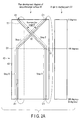
FIG. 2A is a diagram illustrating the manufacture of an optical fiber bundle having a length which is double the circumferential length of the winding member; -
FIG. 2B is a diagram illustrating how the optical fiber bundle is cut with an unshown cutting member; -
FIG. 2C is a diagram illustrating how the optical fiber bundle is removed from the winding member; -
FIG. 2D is a diagram illustrating how the optical fiber bundle is removed from the winding member; -
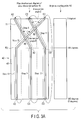
FIG. 3A is a diagram illustrating the manufacture of an optical fiber bundle having a length which is triple the circumferential length of the winding member; -
FIG. 3B is a diagram illustrating how the optical fiber bundle is cut with an unshown cutting member; -
FIG. 3C is a diagram illustrating how the optical fiber bundle is removed from the winding member; and -
FIG. 3D is a diagram illustrating how the optical fiber bundle is removed from the winding member. - Hereinafter, an embodiment of the present invention will be described in detail with reference to the drawings.
- The embodiment is described with reference to
FIG. 1A, FIG. 1B ,FIG. 1C ,FIG. 2A ,FIG. 2B, FIG. 2C ,FIG. 2D ,FIG. 3A ,FIG. 3B, FIG. 3C, and FIG. 3D . In some of the drawings, some of the members are omitted for clarification of the drawings. - As shown in
FIG. 1A , amanufacturing apparatus 10 has amelt apparatus 20 which melts an unshown base material of anoptical fiber 11, and a winding apparatus30 which winds up theoptical fiber 11 when the molten member is linearly drawn and cooled and formed as theoptical fiber 11. - As shown in
FIG. 1A, FIG. 1B , andFIG. 1C , the winding apparatus30 has, for example, a drum-type winding member 40 which has acentral shaft 41 and which rotates around thecentral shaft 41 to wind up theoptical fiber 11, and arotation control portion 50 which is coupled to thecentral shaft 41 and which controls the rotation of the windingmember 40 so that the windingmember 40 rotates around thecentral shaft 41. - As shown in
FIG. 1A, FIG. 1B , andFIG. 1C , the winding apparatus30 further has amovement guide mechanism 60 which guides theoptical fiber 11 to the windingmember 40 when the windingmember 40 winds up theoptical fiber 11, and adetection control unit 70 which detects the rotation angle of the windingmember 40 and which controls themovement guide mechanism 60 on the basis of the detection result. - As shown in
FIG. 1A, FIG. 1B , andFIG. 1C , according to the present embodiment, theoptical fiber 11 is provided along the tangential direction of a later-describedcircumferential surface 43 of the windingmember 40. If the windingmember 40 rotates around thecentral shaft 41 while a distal end portion of theoptical fiber 11 is fixed to the windingmember 40, theoptical fiber 11 is wound around the windingmember 40. - The
manufacturing apparatus 10 manufactures an optical fiber bundle 11a which is formed by bundlingoptical fibers 11. The optical fiber bundle 11a including theoptical fibers 11 is used for, for example, a light guide. Although not shown, theoptical fiber 11 has, for example, a core portion provided in the center of theoptical fiber 11, and a cladding portion covering the core portion. Thisoptical fiber 11 is made of a material such as glass that transmits light. - As shown in
FIG. 1A, FIG. 1B , andFIG. 1C , thecentral shaft 41 is provided to penetrate the windingmember 40 in the width direction of the windingmember 40. Thecentral shaft 41 is provided in the center of the windingmember 40. - As shown in
FIG. 1A, FIG. 1B , andFIG. 1C , the windingmember 40 has thecircumferential surface 43 which is provided around thecentral shaft 41 to surround the entire circumference of thecentral shaft 41. Thecircumferential surface 43 functions as a winding surface to wind up theoptical fiber 11, functions as an outer circumferential surface of the windingmember 40, and functions as a curved surface portion. As long as the windingmember 40 has thecircumferential surface 43, the windingmember 40 has only to have, for example, a circular columnar shape or a circular cylindrical shape. Around thecentral shaft 41, the length of the windingmember 40, i.e., the length of thecircumferential surface 43 is shorter than, for example, the winding length of theoptical fiber 11 to be wound around the windingmember 40. - The winding
member 40 is provided so that thecircumferential surface 43 of the windingmember 40 is located apart from the ground. Thus, for example, both end portions of thecentral shaft 41 are supported by an unshown support member so that thecircumferential surface 43 of the windingmember 40 is located apart from the ground. The support component is, for example, erected on the ground. - The
rotation control portion 50 shown inFIG. 1A controls the rotation and stopping of the windingmember 40 via thecentral shaft 41. Therotation control portion 50 has a drive portion such as a motor to rotate thecentral shaft 41 around thecentral shaft 41. - As shown
FIG. 1B andFIG. 1C , themovement guide mechanism 60 is, for example, provided apart from thecircumferential surface 43, is out of contact with thecircumferential surface 43, faces thecircumferential surface 43 of the windingmember 40, and is provided along the tangential direction. Themovement guide mechanism 60 is provided, for example, on a higher side of the windingmember 40 than thecentral shaft 41 in the height direction of the windingmember 40. Themovement guide mechanism 60 is provided beside a top portion of the windingmember 40 so that a space portion is formed between themovement guide mechanism 60 and the top portion of the windingmember 40 in the diametrical direction of the windingmember 40 that intersects at right angles with the tangential direction of thecircumferential surface 43 and the width direction of thecircumferential surface 43. - As shown
FIG. 1B andFIG. 1C , themovement guide mechanism 60 has a guide member 61 which guides theoptical fiber 11 to the windingmember 40 so that theoptical fiber 11 is wound around the windingmember 40, and a holding-movable portion 63 which holds the guide member 61 and which is movable together the guide member 61 in the width direction of thecircumferential surface 43 of the windingmember 40, i.e., a direction that intersects at right angles with the tangential direction. - As shown
FIG. 1B andFIG. 1C , the guide member 61 has, for example, two plate-shaped members 61a which function as a guide jig. As shownFIG. 1C , the plate-shaped members 61a are provided in parallel for theoptical fiber 11 provided along the tangential direction, sandwich theoptical fiber 11 from both sides in the width direction of thecircumferential surface 43. The guide member 61 is made of a low-friction material having a low frictional coefficient. - Although described in detail later, the guide member 61 guides the
optical fiber 11 in sandwiching state from a point A1 and a point A2 which are starting points of winding to the point A1 and the point A2 which are also end points of winding when theoptical fiber 11 having a length which is N times the circumferential length of the windingmember 40 is manufactured. N is a natural number equal to or more than 2. - In this instance, the guide member 61 guides the
optical fiber 11 so that theoptical fiber 11 once skews in the circumferential direction during one rotation of the windingmember 40, and the guide member 61 performs this skew guide in the same direction every rotation when the windingmember 40 rotates (N-1) times. - In the N-th rotation of the winding
member 40, the guide member 61 performs the guide to theoptical fiber 11 to skew reversely to the direction of shifting in the (N-1) rotations of the windingmember 40 so that theoptical fiber 11 intersects with all theoptical fibers 11 which have skewed in the (N-1) rotations of the windingmember 40 and returns to the starting point. The guide member 61 guides so that an intersection angle θ may be, for example, 5 degrees or more and 40 degrees or less. - This above-mentioned guiding is achieved if the holding-
movable portion 63 which holds the guide member 61 moves in the width direction of thecircumferential surface 43. [Holding-movable portion 63] - As shown
FIG. 1B andFIG. 1C , the holding-movable portion 63 has a holdingmember 63a which holds the guide member 61, and a movingmember 63b to which the holdingmember 63a is fixed and which moves the guide member 61 via the holdingmember 63a in the width direction of thecircumferential surface 43 by moving the guide member 61 in the width direction of thecircumferential surface 43 on the basis of the detection result of thedetection control unit 70, i.e., in accordance with the rotation angle of the windingmember 40. - As shown in
FIG. 1A , thedetection control unit 70 has adetection portion 73 which functions as, for example, an encoder, and amovement control portion 75. - The
detection portion 73 detects the rotation angle of the windingmember 40. - The
movement control portion 75 controls the holding-movable portion 63 so that the holding-movable portion 63 moves in the width direction of thecircumferential surface 43 or the holding-movable portion 63 stops on the basis of the detection result of thedetection portion 73, i.e., the rotation angle of the windingmember 40. - A manufacturing method of the optical fiber bundle 11a having a length which is N times the circumferential length of the winding
member 40 in the winding apparatus30 is described below with reference toFIG. 1A, FIG. 1B ,FIG. 1C ,FIG. 2A ,FIG. 2B, FIG. 2C ,FIG. 2D ,FIG. 3A ,FIG. 3B, FIG. 3C, and FIG. 3D . N is a natural number equal to or more than 2. - In the following, by way of example, the manufacture of the optical fiber bundle 11a having a length which is double the circumferential length of the winding
member 40 is described with reference toFIG. 2A ,FIG. 2B, FIG. 2C, and FIG. 2D , and the manufacture of the optical fiber bundle 11a having a length which is triple the circumferential length of the windingmember 40 is described with reference toFIG. 3A ,FIG. 3B, FIG. 3C, and FIG. 3D . - The unshown base material of the
optical fiber 11 is melted by themelt apparatus 20. As shown inFIG. 1A and FIG. 1B , the melting member is linearly drawn, for example, along the tangential direction of thecircumferential surface 43, naturally cooled, and formed as theoptical fiber 11. The distal end portion of theoptical fiber 11 is guided to thecircumferential surface 43 of the windingmember 40 while being sandwiched between the plate-shaped members 61a, and positioned at and fixed to thecircumferential surface 43. This positioning and fixing part is hereinafter referred to as the point A1 which functions as the starting point, i.e., an initial position. - The winding
member 40 then rotates around thecentral shaft 41 to pull and wind up theoptical fiber 11. In the following, the rotation direction of the windingmember 40 is the same. - As shown in
FIG. 2A , when the windingmember 40 winds up theoptical fiber 11, the guide member 61 guides theoptical fiber 11 so that theoptical fiber 11 is wound around the windingmember 40 from the point A1 which functions as the starting point to a point B1. - As shown in
FIG. 2A , the point B1 is provided out of alignment with the point A1. More specifically, the point B1 is provided a desired angle out of alignment with the point A1 in the circumferential direction. The point B1 is provided, for example, 144 degrees out of alignment with the point A1. The point B1 is not provided on the same circumference as the point A1, but is provided a desired length out of alignment with the point A1 in the width direction of thecircumferential surface 43 which is a direction that intersects at right angles with the circumferential direction and which is a rotation shaft direction. For example, the point B1 is provided to be shifted rightward relative to the point A1. - Thus, in
step 2, theoptical fiber 11 is guided by the guide member 61 to skew relative to the circumferential direction from the point A1 to the point B1, and wound around the windingmember 40 while skewing. - In the above, the
detection portion 73 detects via the windingmember 40 that the windingmember 40 has rotated a desired angle in the circumferential direction and rotated from the point A1 to the point B1. Accordingly, themovement control portion 75 controls the movement of the holding-movable portion 63 so that the guide member 61 moves from the point A1 to the point B1 in the width direction of thecircumferential surface 43. As a result, the holding-movable portion 63 moves in the width direction of thecircumferential surface 43 while holding the guide member 61, and the guide member 61 moves from the point A1 to the point B1 in the width direction of thecircumferential surface 43. As described above, when the windingmember 40 winds up theoptical fiber 11, the guide member 61 guides theoptical fiber 11 so that theoptical fiber 11 skews relative to the circumferential direction from the point A1 to the point B1 and is wound around the windingmember 40. - As shown in
FIG. 2A , when the windingmember 40 further winds up theoptical fiber 11, the guide member 61 guides theoptical fiber 11 so that theoptical fiber 11 is wound around the windingmember 40 from the point B1 to a point C1. - As shown in
FIG. 2A , the point C1 is provided out of alignment with the point B1. More specifically, the point C1 is provided a desired angle out of alignment with the point B1 in the circumferential direction. The point C1 is provided, for example, 216 degrees out of alignment with the point B1. Thus, the point C1 indicates that the windingmember 40 has made one rotation relative to the point A1 in step 1 and is located at a position with the same angle as the point A1 in step 1 in the circumferential direction of the windingmember 40. The point C1 is provided on the same circumference as the point B1. Thus, the point C1 is not provided on the same circumference as the point A1, but is provided a desired length out of alignment with the point A1 in the width direction of thecircumferential surface 43. For example, the point C1 is provided to be shifted rightward relative to the point A1 by the length between the point A1 and the point B1 in the width direction of thecircumferential surface 43. - In
step 3, theoptical fiber 11 is guided by the guide member 61 so that theoptical fiber 11 is linearly provided from the point B1 to the point C1 along the circumferential direction, and theoptical fiber 11 is linearly wound around the windingmember 40. - In the above, the
detection portion 73 detects via the windingmember 40 that the windingmember 40 has rotated a desired angle in the circumferential direction and rotated from the point B1 to the point C1. Accordingly, themovement control portion 75 controls the stopping of the holding-movable portion 63 so that the guide member 61 does not move in the width direction of thecircumferential surface 43. As a result, the holding-movable portion 63 stops without moving in the width direction of thecircumferential surface 43 while holding the guide member 61, and the guide member 61 is fixed in the width direction of thecircumferential surface 43. As described above, when the windingmember 40 winds up theoptical fiber 11, the guide member 61 guides theoptical fiber 11 so that theoptical fiber 11 is linearly wound around the windingmember 40 along the circumferential direction from the point B1 to the point C1. - As shown in
FIG. 2A , when the windingmember 40 further winds up theoptical fiber 11, the guide member 61 guides theoptical fiber 11 so that theoptical fiber 11 is wound around the windingmember 40 from the point C1 to a point D1. - The point D1 is provided out of alignment with the point C1. More specifically, the point D1 is provided a desired angle out of alignment with the point C1 in the circumferential direction. The point D1 is provided, for example, 144 degrees out of alignment with the point C1 (the point A1). Thus, the point D1 indicates the location at the position with the same angle as the point B1 in the circumferential direction of the winding
member 40. The point D1 is not provided on the same circumference as the point C1, but is provided a desired length out of alignment with the point C1 in the width direction of thecircumferential surface 43 so that the point D1 is provided on the same circumference as the point A1. For example, the point D1 is provided to be shifted leftward relative to the point C1 so that the point D1 is provided on the same circumference as the point A1. In this case, the point D1 is provided to be shifted leftward relative to the point B1 by the length between the point A1 and the point C1 in the width direction of thecircumferential surface 43. - In
step 4, theoptical fiber 11 is guided by the guide member 61 to skew relative to the circumferential direction from the point C1 to the point D1, and wound around the windingmember 40 while skewing. In this case, theoptical fiber 11 intersects with theoptical fiber 11 which is provided to skew relative to the circumferential direction from the point A1 to the point B1 instep 2. - In the above, the
detection portion 73 detects via the windingmember 40 that the windingmember 40 has rotated a desired angle in the circumferential direction and rotated from the point C1 to the point D1. Accordingly, themovement control portion 75 controls the movement of the holding-movable portion 63 so that the guide member 61 moves from the point C1 to the point D1 in the width direction of thecircumferential surface 43. As a result, the holding-movable portion 63 moves in the width direction of thecircumferential surface 43 while holding the guide member 61, and the guide member 61 moves from the point C1 to the point D1 in the width direction of thecircumferential surface 43. As described above, when the windingmember 40 winds up theoptical fiber 11, the guide member 61 guides theoptical fiber 11 so that theoptical fiber 11 skews relative to the circumferential direction from the point C1 to the point D1 and is wound around the windingmember 40. - As shown in
FIG. 2A , when the windingmember 40 further winds up theoptical fiber 11, the guide member 61 guides theoptical fiber 11 so that theoptical fiber 11 is wound around the windingmember 40 from the point D1 to the point A1. - As shown in
FIG. 2A , the point A1 is provided out of alignment with the point D1. More specifically, the point A1 is provided a desired angle out of alignment with the point D1 in the circumferential direction. The point A1 is provided, for example, 216 degrees out of alignment with the point D1. The point A1 instep 5 indicates that the windingmember 40 has made two rotations relative to the point A1 in step 1, that the windingmember 40 has made one rotation relative to the point C1 instep 3, and that one cycle of theoptical fiber 11 having a length which is double the circumferential length of the windingmember 40 returns to the starting point in the circumferential length of the windingmember 40. - In
step 5, theoptical fiber 11 is guided by the guide member 61 so that theoptical fiber 11 is linearly provided from the point D1 to the point A1 along the circumferential direction, and theoptical fiber 11 is linearly wound around the windingmember 40. In this case, theoptical fiber 11 is provided parallel to theoptical fiber 11 which is linearly provided from the point B1 to the point C1 along the circumferential direction instep 3. - In the above, the
detection portion 73 detects via the windingmember 40 that the windingmember 40 has rotated a desired angle in the circumferential direction and rotated from the point D1 to the point A1. Accordingly, themovement control portion 75 controls the stopping of the holding-movable portion 63 so that the guide member 61 does not move in the width direction of thecircumferential surface 43. As a result, the holding-movable portion 63 stops without moving in the width direction of thecircumferential surface 43 while holding the guide member 61, and the guide member 61 is fixed in the width direction of thecircumferential surface 43. As described above, when the windingmember 40 winds up theoptical fiber 11, the guide member 61 guides theoptical fiber 11 so that theoptical fiber 11 is linearly wound around the windingmember 40 along the circumferential direction from the point D1 to the point A1. - In
steps member 40 makes two rotations. Theoptical fiber 11 having a length which is double the circumferential length of the windingmember 40 is wound around the windingmember 40 and manufactured. - That is, according to the present embodiment, the
optical fiber 11 having a desired length is manufactured without depending on the circumferential length of the windingmember 40. - In this case, one cycle of the
optical fiber 11 having a length which is double the circumferential length of the windingmember 40 corresponds to two rotations of the windingmember 40. - The operations in
steps member 40 winds up more than oneoptical fiber 11 having a length which is double the circumferential length of the windingmember 40. In the windingmember 40, theoptical fibers 11 are bundled (stacked) in a continuous state, and the optical fiber bundle 11a is thereby formed. The optical fiber bundle 11a is then cut with a cuttingmember 81 in a part other than anintersect portion 80 as shown inFIG. 2B so that optical fiber bundles 11a having a double length will be formed. As shown inFIG. 2C and FIG. 2D , the optical fiber bundles 11a are removed from the windingmember 40. According to the present embodiment, the optical fiber bundle 11a having a length which is double the circumferential length of the windingmember 40 is thus manufactured. - Therefore, according to the present embodiment, a large volume of optical fiber bundles 11a are independently manufactured at a time. As the
manufacturing apparatus 10 independently manufactures a large volume of optical fiber bundles 11a, themanufacturing apparatus 10 does not need to repeat the operation of winding a member around the windingmember 40 to manufacture one optical fiber bundle 11a, removing the manufactured single optical fiber bundle 11a from the windingmember 40, and then again winding the member around the windingmember 40 to manufacture one optical fiber bundle 11a. Thus, according to the present embodiment, a large volume of optical fiber bundles 11a are manufactured without much time and labor and with uniform quality. - Step 1,
step 2, andstep 3 are performed in order as described above. For convenience, the point A1 is referred to as the point A2, the point B1 is referred to as a point B2, and the point C1 is referred to as a point C2. - As shown in
FIG. 3A , when the windingmember 40 further winds up theoptical fiber 11, the guide member 61 guides theoptical fiber 11 so that theoptical fiber 11 is wound around the windingmember 40 from the point C2 to a point D2. - As shown in
FIG. 3A , the point D2 is provided out of alignment with the point C2. More specifically, the point D2 is provided a desired angle out of alignment with the point C2 in the circumferential direction. The point D2 is provided, for example, 144 degrees out of alignment with the point C2. Thus, the point D2 is located at a position with the same angle as the point B2 in the circumferential direction of the windingmember 40. The point D2 is not provided on the same circumference as the point C2, but is provided a desired length out of alignment with the point C2 in the width direction of thecircumferential surface 43 so that the point D2 is provided to be shifted rightward relative to the point C2. In this case, the point D2 is provided to be shifted rightward relative to the point B2 by the length between the point A2 and the point C2 in the width direction of thecircumferential surface 43. - Thus, in
step 11, theoptical fiber 11 is guided by the guide member 61 to skew relative to the circumferential direction from the point C2 to the point D2, and wound around the windingmember 40 while skewing. In this case, theoptical fiber 11 is provided parallel to theoptical fiber 11 which is provided to skew relative to the circumferential direction from the point A2 to the point B2 instep 2. - In the above, the
detection portion 73 detects via the windingmember 40 that the windingmember 40 has rotated a desired angle in the circumferential direction and rotated from the point C2 to the point D2. Accordingly, themovement control portion 75 controls the movement of the holding-movable portion 63 so that the guide member 61 moves from the point C2 to the point D2 in the width direction of thecircumferential surface 43. As a result, the holding-movable portion 63 moves in the width direction of thecircumferential surface 43 while holding the guide member 61, and the guide member 61 moves from the point C2 to the point D2 in the width direction of thecircumferential surface 43. As described above, when the windingmember 40 winds up theoptical fiber 11, the guide member 61 guides theoptical fiber 11 so that theoptical fiber 11 skews relative to the circumferential direction from the point C2 to the point D2 and is wound around the windingmember 40. - As shown in
FIG. 3A , when the windingmember 40 further winds up theoptical fiber 11, the guide member 61 guides theoptical fiber 11 so that theoptical fiber 11 is wound around the windingmember 40 from the point D2 to a point E2. - As shown in
FIG. 3A , the point E2 is provided out of alignment with the point D2. More specifically, the point E2 is provided a desired angle out of alignment with the point D2 in the circumferential direction. The point E2 is provided, for example, 216 degrees out of alignment with the point D2. Thus, the point E2 indicates that the windingmember 40 has made two rotations relative to the point A2 in step 1, and that the windingmember 40 has made one rotation relative to the point C2 instep 3, and indicates the location at the position with the same angle as the point A2 and the point C2 in the circumferential direction of the windingmember 40. The point E2 is provided on the same circumference as the point D2. Thus, the point E2 is not provided on the same circumference as the point A2 and the point C2, but is provided a desired length out of alignment with the point A2 and the point C2 in the width direction of thecircumferential surface 43. For example, the point E2 is provided to be shifted rightward relative to the point C2 by the length between the point A2 and the point B2 in the width direction of thecircumferential surface 43. In other words, the point E2 is provided to be shifted rightward relative to the point C2 by the length between the point A2 and the point C2 in the width direction of thecircumferential surface 43. - In
step 12, theoptical fiber 11 is guided by the guide member 61 so that theoptical fiber 11 is linearly provided from the point D2 to the point E2 along the circumferential direction, and theoptical fiber 11 is linearly wound around the windingmember 40. In this case, theoptical fiber 11 is provided parallel to theoptical fiber 11 which is linearly provided from the point B2 to the point C2 along the circumferential direction instep 3. - In the above, the
detection portion 73 detects via the windingmember 40 that the windingmember 40 has rotated a desired angle in the circumferential direction and rotated from the point D2 to the point E2. Accordingly, themovement control portion 75 controls the stopping of the holding-movable portion 63 so that the guide member 61 does not move in the width direction of thecircumferential surface 43. As a result, the holding-movable portion 63 stops without moving in the width direction of thecircumferential surface 43 while holding the guide member 61, and the guide member 61 is fixed in the width direction of thecircumferential surface 43. As described above, when the windingmember 40 winds up theoptical fiber 11, the guide member 61 guides theoptical fiber 11 so that theoptical fiber 11 is linearly wound around the windingmember 40 along the circumferential direction from the point D2 to the point E2. - As shown in
FIG. 3A , when the windingmember 40 further winds up theoptical fiber 11, the guide member 61 guides theoptical fiber 11 so that theoptical fiber 11 is wound around the windingmember 40 from the point E2 to a point F2. - As shown in
FIG. 3A , the point F2 is provided out of alignment with the point E2. More specifically, the point F2 is provided a desired angle out of alignment with the point E2 in the circumferential direction. The point F2 is provided, for example, 144 degrees out of alignment with the point E2 (the point A2). Thus, the point F2 indicates the location at the position with the same angle as the point B2 and the point D2 in the circumferential direction of the windingmember 40. The point F2 is not provided on the same circumference as the point E2, but is provided a desired length out of alignment with the point E2 in the width direction of thecircumferential surface 43 so that the point F2 is provided on the same circumference as the point A2. For example, the point F2 is provided to be shifted leftward relative to the point E2 so that the point F2 is provided on the same circumference as the point A2. In this case, the point F2 is provided to be shifted leftward relative to the point B2 by the length between the point A2 and the point C2 in the width direction of thecircumferential surface 43. The point F2 is also provided to be shifted leftward relative to the point D2 by the length between the point A2 and the point E2 in the width direction of thecircumferential surface 43. - In
step 13, theoptical fiber 11 is guided by the guide member 61 to skew relative to the circumferential direction from the point E2 to the point F2, and wound around the windingmember 40 while skewing. In this case, theoptical fiber 11 intersects with theoptical fiber 11 which is provided to skew relative to the circumferential direction from the point A2 to the point B2 instep 2, and theoptical fiber 11 which is provided to skew relative to the circumferential direction from the point C2 to the point D2 instep 11. - In the above, the
detection portion 73 detects via the windingmember 40 that the windingmember 40 has rotated a desired angle in the circumferential direction and rotated from the point E2 to the point F2. Accordingly, themovement control portion 75 controls the movement of the holding-movable portion 63 so that the guide member 61 moves from the point E2 to the point F2 in the width direction of thecircumferential surface 43. As a result, the holding-movable portion 63 moves in the width direction of thecircumferential surface 43 while holding the guide member 61, and the guide member 61 moves from the point E2 to the point F2 in the width direction of thecircumferential surface 43. As described above, when the windingmember 40 winds up theoptical fiber 11, the guide member 61 guides theoptical fiber 11 so that theoptical fiber 11 skews relative to the circumferential direction from the point E2 to the point F2 and is wound around the windingmember 40. - As shown in
FIG. 3A , when the windingmember 40 further winds up theoptical fiber 11, the guide member 61 guides theoptical fiber 11 so that theoptical fiber 11 is wound around the windingmember 40 from the point F2 to the point A2. - As shown in
FIG. 3A , the point A2 is provided out of alignment with the point F2. More specifically, the point A2 is provided a desired angle out of alignment with the point F2 in the circumferential direction. The point A2 is provided, for example, 216 degrees out of alignment with the point F2. Thus, the point A2 instep 14 indicates that the windingmember 40 has made three rotations relative to the point A2 in step 1, and that one cycle of theoptical fiber 11 having a length which is triple the circumferential length of the windingmember 40 returns to the starting point in the circumferential length of the windingmember 40. - In
step 14, theoptical fiber 11 is guided by the guide member 61 so that theoptical fiber 11 is linearly provided from the point F2 to the point A2 along the circumferential direction, and theoptical fiber 11 is linearly wound around the windingmember 40. In this case, theoptical fiber 11 is provided parallel to theoptical fiber 11 which is linearly provided from the point B2 to the point C2 along the circumferential direction instep 3, and theoptical fiber 11 which is linearly provided from the point D2 to the point E2 along the circumferential direction instep 12. - In the above, the
detection portion 73 detects via the windingmember 40 that the windingmember 40 has rotated a desired angle in the circumferential direction and rotated from the point F2 to the point A2. Accordingly, themovement control portion 75 controls the stopping of the holding-movable portion 63 so that the guide member 61 does not move in the width direction of thecircumferential surface 43. As a result, the holding-movable portion 63 stops without moving in the width direction of thecircumferential surface 43 while holding the guide member 61, and the guide member 61 is fixed in the width direction of thecircumferential surface 43. As described above, when the windingmember 40 winds up theoptical fiber 11, the guide member 61 guides theoptical fiber 11 so that theoptical fiber 11 is linearly wound around the windingmember 40 along the circumferential direction from the point F2 to the point A2. - In
steps member 40 makes three rotations. Theoptical fiber 11 having a length which is triple the circumferential length of the windingmember 40 is thus manufactured. - That is, according to the present embodiment, the
optical fiber 11 having a desired length is manufactured without depending on the circumferential length of the windingmember 40. - In this case, one cycle of the
optical fiber 11 having a length which is triple the circumferential length of the windingmember 40 corresponds to three rotations of the windingmember 40. - The operations in
steps member 40 winds up more than oneoptical fiber 11 having a length which is triple the circumferential length of the windingmember 40. In the windingmember 40, theoptical fibers 11 are bundled (stacked) in a continuous state, and the optical fiber bundle 11a is thereby formed. The optical fiber bundle 11a is then cut with the cuttingmember 81 in a part other than theintersect portion 80 as shown inFIG. 3B so that optical fiber bundles 11a having a triple length will be formed. As shown inFIG. 3C and FIG. 3D , the optical fiber bundles 11a are removed from the windingmember 40. According to the present embodiment, the optical fiber bundle 11a having a length which is triple the circumferential length of the windingmember 40 is thus formed. - Therefore, according to the present embodiment, a large volume of optical fiber bundles 11a are independently manufactured at a time. When the
manufacturing apparatus 10 independently manufactures a large volume of optical fiber bundles 11a, themanufacturing apparatus 10 does not need to repeat the operation of winding a member around the windingmember 40 to manufacture one optical fiber bundle 11a, removing the manufactured single optical fiber bundle 11a from the windingmember 40, and then again winding the member around the windingmember 40 to manufacture one optical fiber bundle 11a. Thus, according to the present embodiment, a large volume of optical fiber bundles 11a are manufactured without much time and labor and with uniform quality. - As described above, when the
manufacturing apparatus 10 manufactures an optical fiber bundle 11a having a length which is N times the circumferential of the windingmember 40, the windingmember 40 rotates N times to wind up theoptical fiber 11. N is a natural number equal to or more than 2. - When the winding
member 40 rotates (N-1) times with respect to a desired starting point as a standard, theoptical fiber 11 is once skewed relative to the circumferential direction by the guide member 61 and further shifted by a desired length in the width direction of thecircumferential surface 43 while the windingmember 40 is making one rotation. In this state, the windingmember 40 winds up theoptical fiber 11. This operation is performed in the same direction every rotation when the windingmember 40 rotates (N-1) times. This shift process is performed. - In the N-th rotation of the winding
member 40, the guide member 61 performs the guide to theoptical fiber 11 to skew reversely to the direction of shifting in the (N-1) rotations of the windingmember 40 so that theoptical fiber 11 intersects with all theoptical fibers 11 which have skewed in the (N-1) rotations of the windingmember 40 and the end point of theoptical fiber 11 having a length which is N times returns to the starting point. In this state, the windingmember 40 winds up theoptical fiber 11. This reverse shift process is performed. - The linear process in
step 3 may be omitted. - This operation is one cycle of the
optical fiber 11 having a length which is N times the circumference of the windingmember 40. - In the above, the
optical fiber 11 is wound around the windingmember 40 while theoptical fiber 11 is being guided by the guide member 61. Owing to the constant guidance by the guide member 61, the entanglement of theoptical fibers 11 is prevented. - In the above, the
guide member 11 moves in the width direction of thecircumferential surface 43 so that theoptical fiber 11 skews. Since the guide member 61 moves, the windingmember 40 does not need to be moved, and the configuration of themanufacturing apparatus 10 is simpler. - In the above, the guide member 61 guides the
optical fiber 11 so that theoptical fiber 11 is linearly provided along the circumferential direction except during skewing. In this state, the windingmember 40 winds up theoptical fiber 11. Thus, the entanglement of theoptical fibers 11 is prevented. - As a result of the above, the
optical fiber 11 is regularly wound around the windingmember 40. - The above operation is repeated so that an optical fiber bundle 11a formed by bundling the
optical fibers 11 having a length which is N times the circumference of the windingmember 40 is manufactured. In the windingmember 40, theoptical fiber 11 is cut with the cuttingmember 81 so that the optical fiber bundles 11a having a length which is N times will be formed, and theoptical fiber 11 is removed from the windingmember 40. In this way, an optical fiber bundle 11a having a length which is N times the circumferential length of the windingmember 40 is manufactured. - According to the present embodiment, the
optical fiber 11 is once skewed relative to the circumferential direction of the windingmember 40 and shifted by a desired length in the width direction of thecircumferential surface 43 and then wound around the windingmember 40 during one rotation of the windingmember 40 and every rotation of the windingmember 40 when the windingmember 40 rotates (N-1) times with respect to a desired starting point as a standard. - In the N-th rotation of the winding
member 40, theoptical fiber 11 is skewed reversely to the direction of shifting in the (N-1) rotations of the windingmember 40 so that theoptical fiber 11 intersects with all theoptical fibers 11 which have skewed in the (N-1) rotations of the windingmember 40 and the end point of theoptical fiber 11 having a length which is N times returns to the starting point whereby theoptical fiber 11 is wound around the windingmember 40. - The above operation is one cycle of the
optical fiber 11 having a length which is N times the circumference of the windingmember 40. The above operation is repeated so that an optical fiber bundle 11a formed by bundling theoptical fibers 11 having a length which is N times the circumference of the windingmember 40 is manufactured. - Therefore, according to the present embodiment, it is possible to provide a manufacturing method of the optical fiber bundle 11a which enables the manufacture of a large volume of optical fiber bundles 11a with uniform quality at low cost, without much time and labor and without depending on the circumferential length of the winding
member 40. - According to the present embodiment, it is possible to manufacture an optical fiber bundle 11a which is longer than the circumferential length of the existing winding
member 40, a new windingmember 40 does not need to be manufactured, and manufacturing costs for the optical fiber bundle 11a can be suppressed. - According to the present embodiment, a large volume of optical fiber bundles 11a are independently manufactured at a time. As the
manufacturing apparatus 10 independently manufactures a large volume of optical fiber bundles 11a, themanufacturing apparatus 10 does not need to repeat the operation of winding a member around the windingmember 40 to manufacture one optical fiber bundle 11a, removing the manufactured single optical fiber bundle 11a from the windingmember 40, and then again winding the material around the windingmember 40 to manufacture one optical fiber bundle 11a. Thus, according to the present embodiment, a large volume of optical fiber bundles 11a are manufactured without much time and labor and with uniform quality. - According to the present embodiment, in the above, owing to the constant guidance by the guide member 61, the entanglement of the
optical fibers 11 can be prevented when the windingmember 40 winds up theoptical fiber 11. - According to the present embodiment, the guide member 61 moves in the width direction of the
circumferential surface 43, so that theoptical fiber 11 skews, and the configuration of themanufacturing apparatus 10 can be simpler. - According to the present embodiment, except during skewing, the guide member 61 guides the
optical fiber 11 so that theoptical fiber 11 is linearly provided along the circumferential direction. In this state, the windingmember 40 winds up theoptical fiber 11. Thus, according to the present embodiment, the entanglement of theoptical fibers 11 can be prevented. - According to the present embodiment, the
optical fiber 11 can be regularly wound around the windingmember 40 as a result of the above. - According to the present embodiment, the optical fiber bundle 11a is cut in a part other than the
intersect portion 80 and then removed from the windingmember 40. Thus, according to the present embodiment, the optical fiber bundle 11a can be disentangled so that the optical fiber bundle 11a does not come apart, and the optical fiber bundle 11a can be easily removed. - According to the present embodiment, the guide member 61 guides so that the intersection angle θ may be, for example, 5 degrees or more and 40 degrees or less. Thus, according to the present embodiment, the optical fiber bundle 11a can be disentangled so that the optical fiber bundle 11a does not come apart, and the optical fiber bundle 11a can be easily removed. Moreover, it is possible to easily perform a bundling operation to bundle the optical fiber bundles 11a so that the removed optical fiber bundle 11a does not come apart.
- Although the point B1 is provided, for example, 144 degrees out of alignment with the point A1, this angle is not specifically limited, and a desired angle can be set in consideration of, for example, the intersection angle. This also holds true with the point D1 and other points.
- The present invention is not completely limited to the embodiment described above, and the components can be modified without departing the spirit of the invention at the time of carrying out the invention. Various inventions can be made by properly combining the components disclosed in the embodiment described above.
Claims (5)
- A manufacturing method of an optical fiber bundle in which a winding member rotates N times (N is a natural number equal to or more than 2) to wind up an optical fiber and thereby manufacture an optical fiber bundle having a length that is N times the circumference of the winding member, the method comprising:a shift process of once skewing the optical fiber relative to the circumferential direction of the winding member and shifting the optical fiber a desired length in the width direction of a circumferential surface of the winding member and then winding the optical fiber around the winding member during one rotation of the winding member and every rotation of the winding member when the winding member rotates (N-1) times with respect to a desired starting point as a standard; anda reverse shift process of skewing the optical fiber reversely to the direction of shifting in the (N-1) rotations of the winding member so that the optical fiber intersects with all the optical fibers which have skewed in the (N-1) rotations of the winding member and the end point of the optical fiber having a length which is N times returns to the starting point in the N-th rotation of the winding member whereby the optical fiber is wound around the winding member,wherein the operation is one cycle of the optical fiber having a length which is N times the circumference of the winding member, and the operation is repeated so that an optical fiber bundle formed by bundling the optical fibers having a length which is N times the circumference of the winding member is manufactured.
- The manufacturing method of the optical fiber bundle according to claim 1, wherein the winding member winds up the optical fiber while the optical fiber is being guided by a guide member.
- The manufacturing method of the optical fiber bundle according to claim 2, wherein the guide member moves in the width direction of the circumferential surface so that the optical fiber skews.
- The manufacturing method of the optical fiber bundle according to claim 3, wherein except during skewing, the guide member guides the optical fiber so that the optical fiber is linearly provided along the circumferential direction.
- The manufacturing method of the optical fiber bundle according to claim 4, wherein the optical fiber bundle is cut in a part other than an intersect portion and then removed from the winding member.
Applications Claiming Priority (2)
| Application Number | Priority Date | Filing Date | Title |
|---|---|---|---|
| JP2013270394 | 2013-12-26 | ||
| PCT/JP2014/074493 WO2015098204A1 (en) | 2013-12-26 | 2014-09-17 | Manufacturing method for optical fiber bundles |
Publications (2)
| Publication Number | Publication Date |
|---|---|
| EP3088341A1 true EP3088341A1 (en) | 2016-11-02 |
| EP3088341A4 EP3088341A4 (en) | 2017-10-25 |
Family
ID=53478086
Family Applications (1)
| Application Number | Title | Priority Date | Filing Date |
|---|---|---|---|
| EP14874024.4A Withdrawn EP3088341A4 (en) | 2013-12-26 | 2014-09-17 | Manufacturing method of optical fiber bundles |
Country Status (5)
| Country | Link |
|---|---|
| US (1) | US9457984B2 (en) |
| EP (1) | EP3088341A4 (en) |
| JP (1) | JP5816776B1 (en) |
| CN (1) | CN105555693B (en) |
| WO (1) | WO2015098204A1 (en) |
Families Citing this family (2)
| Publication number | Priority date | Publication date | Assignee | Title |
|---|---|---|---|---|
| WO2015052951A1 (en) * | 2013-10-07 | 2015-04-16 | 株式会社フジクラ | Optical fiber unit, method for branching optical fiber, and optical fiber cable |
| JP2021183991A (en) | 2018-07-04 | 2021-12-02 | オリンパス株式会社 | Light guide, endoscope with light guide, optical fiber bundle manufacturing device and optical fiber bundle manufacturing method |
Family Cites Families (11)
| Publication number | Priority date | Publication date | Assignee | Title |
|---|---|---|---|---|
| JPS3927279B1 (en) * | 1961-05-17 | 1964-11-28 | ||
| JPS4618784B1 (en) * | 1965-03-31 | 1971-05-26 | ||
| JPS466284A (en) | 1970-05-07 | 1971-12-08 | ||
| JPS5313437A (en) * | 1976-07-23 | 1978-02-07 | Asahi Optical Co Ltd | Method of manufacturing optical fiber bundle |
| JPS61124477A (en) * | 1984-11-22 | 1986-06-12 | Sumitomo Electric Ind Ltd | Reel winding method |
| JP2884450B2 (en) | 1991-07-04 | 1999-04-19 | 株式会社フジクラ | Winding machine with bobbin traverse width variation mechanism |
| JPH08208115A (en) | 1995-01-31 | 1996-08-13 | Kenichi Konno | Cable winding device |
| JP2001343537A (en) * | 2000-05-31 | 2001-12-14 | Mitsubishi Rayon Co Ltd | Optical fiber bundle and method of manufacturing optical fiber bundle |
| JP2001343538A (en) * | 2000-05-31 | 2001-12-14 | Mitsubishi Rayon Co Ltd | Manufacturing method of optical fiber bundle and insertion jig |
| US6493492B1 (en) * | 2000-08-28 | 2002-12-10 | Lucent Technologies Inc. | Fiber bundle and optical amplifier |
| CN102393547A (en) * | 2011-12-08 | 2012-03-28 | 南京烽火藤仓光通信有限公司 | Optical fiber bundle and manufacturing method thereof |
-
2014
- 2014-09-17 CN CN201480051580.5A patent/CN105555693B/en active Active
- 2014-09-17 WO PCT/JP2014/074493 patent/WO2015098204A1/en not_active Ceased
- 2014-09-17 JP JP2015522316A patent/JP5816776B1/en active Active
- 2014-09-17 EP EP14874024.4A patent/EP3088341A4/en not_active Withdrawn
-
2016
- 2016-01-28 US US15/008,714 patent/US9457984B2/en active Active
Also Published As
| Publication number | Publication date |
|---|---|
| US20160159607A1 (en) | 2016-06-09 |
| CN105555693A (en) | 2016-05-04 |
| JPWO2015098204A1 (en) | 2017-03-23 |
| WO2015098204A1 (en) | 2015-07-02 |
| JP5816776B1 (en) | 2015-11-18 |
| EP3088341A4 (en) | 2017-10-25 |
| CN105555693B (en) | 2017-11-28 |
| US9457984B2 (en) | 2016-10-04 |
Similar Documents
| Publication | Publication Date | Title |
|---|---|---|
| CN101345460B (en) | Winding method and winding device | |
| CN101378212B (en) | Winding device | |
| JP5809899B2 (en) | Fiber bundle feeder | |
| CN104662783B (en) | Winding device and winding method | |
| CN111052278B (en) | Winding device and winding method using same | |
| JP5450687B2 (en) | Optical fiber ribbon manufacturing method and optical fiber ribbon manufacturing apparatus | |
| US10027208B2 (en) | Coil installation method and coil installation jig | |
| CN101978582A (en) | Apparatus and methods for winding supports for coils and single poles of cores of dynamo electric machines | |
| US20080017746A1 (en) | Automatic winder for an inside brushless stator | |
| EP3088341A1 (en) | Manufacturing method of optical fiber bundles | |
| JP2016528129A (en) | Microduct tube winder, double station winder, processing system for empty microduct plastic tube, and method for winding such a tube | |
| US11901777B2 (en) | Winding device and wire winding method | |
| KR102021662B1 (en) | motor coil winding apparatus to array multi coil and its method | |
| JP6232238B2 (en) | Winding device and winding method | |
| JP2007173264A (en) | Multiaxial winding machine | |
| JP2014075957A (en) | Winding device | |
| KR20060031177A (en) | Continuous winding device of multiple split cores and winding method thereof using universal winding machine of single spindle structure | |
| EP3460965B1 (en) | Winding method | |
| CN107078613B (en) | Method and segment mandrel for winding multiple formers | |
| JP2017114713A (en) | Production method of strand and strand production apparatus | |
| JP6748092B2 (en) | Apparatus and method for handling wound yarn strands | |
| JP2015132682A (en) | Apparatus and method for manufacturing intermittently cut optical fiber ribbon | |
| WO2020039884A1 (en) | Wire winding device and wire winding method | |
| JP2016098103A (en) | Yarn path guide device and thread path guide method | |
| JP7536627B2 (en) | Winding device and winding method |
Legal Events
| Date | Code | Title | Description |
|---|---|---|---|
| PUAI | Public reference made under article 153(3) epc to a published international application that has entered the european phase |
Free format text: ORIGINAL CODE: 0009012 |
|
| 17P | Request for examination filed |
Effective date: 20160719 |
|
| AK | Designated contracting states |
Kind code of ref document: A1 Designated state(s): AL AT BE BG CH CY CZ DE DK EE ES FI FR GB GR HR HU IE IS IT LI LT LU LV MC MK MT NL NO PL PT RO RS SE SI SK SM TR |
|
| AX | Request for extension of the european patent |
Extension state: BA ME |
|
| DAX | Request for extension of the european patent (deleted) | ||
| A4 | Supplementary search report drawn up and despatched |
Effective date: 20170922 |
|
| RIC1 | Information provided on ipc code assigned before grant |
Ipc: B65H 54/28 20060101ALI20170918BHEP Ipc: G02B 6/04 20060101ALI20170918BHEP Ipc: B65H 55/04 20060101ALI20170918BHEP Ipc: B65H 54/58 20060101ALI20170918BHEP Ipc: B65H 54/02 20060101AFI20170918BHEP |
|
| STAA | Information on the status of an ep patent application or granted ep patent |
Free format text: STATUS: EXAMINATION IS IN PROGRESS |
|
| 17Q | First examination report despatched |
Effective date: 20190417 |
|
| STAA | Information on the status of an ep patent application or granted ep patent |
Free format text: STATUS: THE APPLICATION IS DEEMED TO BE WITHDRAWN |
|
| 18D | Application deemed to be withdrawn |
Effective date: 20190828 |