EP3088293A2 - Kajak mit rekonfigurierbarer mittlerer arbeitsbrücke - Google Patents
Kajak mit rekonfigurierbarer mittlerer arbeitsbrücke Download PDFInfo
- Publication number
- EP3088293A2 EP3088293A2 EP16165531.1A EP16165531A EP3088293A2 EP 3088293 A2 EP3088293 A2 EP 3088293A2 EP 16165531 A EP16165531 A EP 16165531A EP 3088293 A2 EP3088293 A2 EP 3088293A2
- Authority
- EP
- European Patent Office
- Prior art keywords
- kayak
- console
- cover
- kit
- bottom wall
- Prior art date
- Legal status (The legal status is an assumption and is not a legal conclusion. Google has not performed a legal analysis and makes no representation as to the accuracy of the status listed.)
- Withdrawn
Links
- XLYOFNOQVPJJNP-UHFFFAOYSA-N water Substances O XLYOFNOQVPJJNP-UHFFFAOYSA-N 0.000 claims description 8
- 210000003813 thumb Anatomy 0.000 claims description 4
- 241000251468 Actinopterygii Species 0.000 description 5
- 241000276420 Lophius piscatorius Species 0.000 description 5
- 230000004048 modification Effects 0.000 description 4
- 238000012986 modification Methods 0.000 description 4
- 239000000463 material Substances 0.000 description 2
- 238000000034 method Methods 0.000 description 2
- 230000009471 action Effects 0.000 description 1
- 229910052782 aluminium Inorganic materials 0.000 description 1
- XAGFODPZIPBFFR-UHFFFAOYSA-N aluminium Chemical compound [Al] XAGFODPZIPBFFR-UHFFFAOYSA-N 0.000 description 1
- -1 aluminum Chemical class 0.000 description 1
- 230000008901 benefit Effects 0.000 description 1
- 229910052751 metal Inorganic materials 0.000 description 1
- 239000002184 metal Substances 0.000 description 1
- 150000002739 metals Chemical class 0.000 description 1
- 229920000642 polymer Polymers 0.000 description 1
- 230000008569 process Effects 0.000 description 1
- 239000011435 rock Substances 0.000 description 1
Images

Classifications
-
- B—PERFORMING OPERATIONS; TRANSPORTING
- B63—SHIPS OR OTHER WATERBORNE VESSELS; RELATED EQUIPMENT
- B63B—SHIPS OR OTHER WATERBORNE VESSELS; EQUIPMENT FOR SHIPPING
- B63B25/00—Load-accommodating arrangements, e.g. stowing, trimming; Vessels characterised thereby
- B63B25/002—Load-accommodating arrangements, e.g. stowing, trimming; Vessels characterised thereby for goods other than bulk goods
- B63B25/004—Load-accommodating arrangements, e.g. stowing, trimming; Vessels characterised thereby for goods other than bulk goods for containers
-
- A—HUMAN NECESSITIES
- A01—AGRICULTURE; FORESTRY; ANIMAL HUSBANDRY; HUNTING; TRAPPING; FISHING
- A01K—ANIMAL HUSBANDRY; AVICULTURE; APICULTURE; PISCICULTURE; FISHING; REARING OR BREEDING ANIMALS, NOT OTHERWISE PROVIDED FOR; NEW BREEDS OF ANIMALS
- A01K97/00—Accessories for angling
- A01K97/10—Supports for rods
-
- B—PERFORMING OPERATIONS; TRANSPORTING
- B63—SHIPS OR OTHER WATERBORNE VESSELS; RELATED EQUIPMENT
- B63B—SHIPS OR OTHER WATERBORNE VESSELS; EQUIPMENT FOR SHIPPING
- B63B34/00—Vessels specially adapted for water sports or leisure; Body-supporting devices specially adapted for water sports or leisure
- B63B34/20—Canoes, kayaks or the like
- B63B34/21—Canoes, kayaks or the like characterised by constructional features
-
- B—PERFORMING OPERATIONS; TRANSPORTING
- B63—SHIPS OR OTHER WATERBORNE VESSELS; RELATED EQUIPMENT
- B63B—SHIPS OR OTHER WATERBORNE VESSELS; EQUIPMENT FOR SHIPPING
- B63B34/00—Vessels specially adapted for water sports or leisure; Body-supporting devices specially adapted for water sports or leisure
- B63B34/26—Accessories for canoes, kayaks or the like
Definitions
- the present disclosure relates to watercraft, such as kayaks. More particularly this disclosure relates to a staging or storage system for these watercraft.
- anglers are rediscovering the accessibility, portability, quiet travel, and lower cost of fishing from canoes and kayaks as was common hundreds of years ago. These small boats can travel into shallow water, marshes, and through narrow passages that larger boats cannot. Kayak fishing provides access to bodies of water that may be off limits to motor driven boats. Traveling in a kayak is also quieter above and below the water to avoid alerting the fish below. Anglers who use kayaks also spend less time and effort transporting, launching, pulling and maintaining their boats, to provide more time on the water catching fish.
- a kayak configured to help the fisherman maintain their necessary items in a secure, organized and easy to reach location so the items can be accessed in a hurry during the rush of motion required for securing the catch.
- a kayak with customizable storage based on the individual needs of the user.
- the kayak may have a shell having a hull and a cockpit.
- the kayak may also have a console located within the cockpit of the kayak.
- the console may have a bottom wall separate from the hull and at least one side wall extending upwardly from a periphery of the bottom wall to at least partially define a storage compartment.
- the console may also have a replaceable cover.
- the replaceable cover may have a plurality of apertures of varied dimensions for organizing equipment at least partially staged within the storage compartment.
- kits may include a kayak having a shell including a hull and a cockpit.
- the kit may also include a console approximately centrally located within the cockpit along a widthwise direction of the kayak; the console having a bottom wall separate from the hull, and at least one side wall extending upwardly from a periphery of the bottom wall to at least partially define a storage compartment.
- the console may be integral with the kayak.
- the kit may also include at least two replaceable covers for the console.
- the replaceable covers each have a plurality of apertures for organizing equipment at least partially staged within the storage compartment.
- a first replaceable cover has a first arrangement of the plurality of apertures
- a second replaceable cover has a second arrangement of the plurality of apertures, the second arrangement being different from the first.
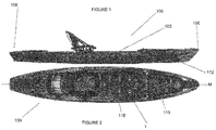
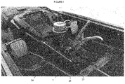
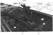
- FIGs. 1 and 2 show a kayak 100 according to embodiments of the present disclosure.
- the term “kayak” is used generally to describe watercraft or boats that are less than about 16 feet long, less about 4 feet wide and weigh less than about 150 pounds.
- the "kayak” may be considered a personal watercraft, but is not limited to a single occupant.
- the term “kayak” includes boats generally referred to as canoes, and also includes stand-up paddle boards.
- the term “kayak” also includes watercraft that may be generally referred to as rowboats.
- “kayaks” are not limited to paddle powered boats, but also include pedal powered boats, or boats with electric motors.
- the kayak 100 includes a shell 103 having a bow 106 and a stern 109.
- the shell 103 is shaped to form a hull 112 along the bottom thereof and a deck 115 along the top thereof.
- a cavity may be formed between the hull 112 and the deck 115 for buoyancy or for storage.
- the shell 103 may generally define a cockpit 118.
- the cockpit 118 is generally understood as the portion of the kayak 100 in which the user is intended to sit or stand.
- the cockpit 118 is located approximately mid-ship along a bow-stern direction.
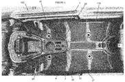
- a console 1 is located within the cockpit 118 and may be itself located approximately mid-ship along a bow-stern direction.
- portions of the console 1 are integrally molded or otherwise formed with the shell 103.
- the console 1 may be a separate component attached within the cockpit 118 by fasteners, tie downs, etc.
- the console 1 may be referred to as a center console 1 when it is located near the midline M of the kayak 100, for example, approximately centered along a widthwise direction of the kayak 100.
- the central bow-stern location of the console 1 positions the console 1 generally ahead of the user when seated in the cockpit 12.
- the central widthwise location of the console may generally position the console between the legs of a seated user. This location is believed to be well within arm's length reach for a user without requiring the user to turn around within the kayak 100.
- the console 1 is located in a highly accessible location within the kayak 100 for quick and easy access without unnecessary movement of the user, which could cause unnecessary movement of the kayak 100.
- the console 1 may have a bottom wall 4.
- the bottom wall 4 is separate from and spaced from an inner surface of the hull 112.
- the bottom wall 4 is distinct from the hull 112.
- the bottom wall 4 may or may not include a scupper hole leading through the hull 112.
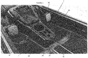
- the console 1 may also include at least one side wall 7 extending upwardly from a periphery of the bottom wall 4 to at least partially define a storage compartment 10.
- the storage compartment 10 should be understood as a distinct space from the optional cavity formed between the hull 112 and the deck 115. Whether a single continuous wall or several separate walls, the at least one side wall 7 forms the periphery of the storage compartment 10.
- the storage compartment 10, may be understood as an open-top recess when considering the bottom wall 4 and the at least one side wall 7 alone.
- the top of the storage compartment 10 may be formed by a replaceable cover 20.
- the replaceable cover 20 may have a plurality of apertures 24-27 of varied dimensions for organizing equipment, such as grips, pliers, knives, etc., at least partially staged within the storage compartment 10.
- Each tool may fit within one or more of the plurality of apertures 24-27 in a manner that securely stages the tool and minimizes the likelihood that tools will become inadvertently dislodged from the console 1.
- the user can become accustomed to where within the cover 20 each particular piece of equipment is staged, further simplifying the retrieval process while engaged with a fish.
- the exterior dimensions of the cover 20 may be dictated in part by the shape of the bottom wall 4, the circumference of the at least one side wall 7, and the shape of the storage compartment 10.
- the exterior dimensions of the cover 20 are therefore not particularly limited.
- the material of the cover 20 should be relatively strong, stiff and light weight.
- the material of the cover 20 is not particularly limited, but may include metals such as aluminum, as well as polymers.
- the cover 20 may be fixed to a top end of the at least one side wall 7 by a thumb screw 30 or other similar fastener.
- a single thumb screw 30 placed near a stern end of the cover 20 may be sufficient to hold the cover 20 in place.
- tabs 33 are formed or attached to an upper end of one or more of the at least one side walls 7. The tabs 33 may hold the cover 20 in place against the at least one side wall 7 without fastening the cover 20 to the at least one side wall 7 at the locations corresponding to the tabs 33.
- an upper end of the at least one side wall 7 can include a recess 36 to allow the cover 20 to be flush mounted with at least a portion of the console 1.
- the plurality of apertures 24-27 in the cover 20 may be through apertures allowing the staged items to reach the bottom wall 4. In some embodiments, some or all of the apertures 24-27 may be blind apertures to prevent water from reaching the bottom wall 4 though the aperture itself.
- the plurality of apertures 24-27 may include a round aperture 24 sized to accept a water bottle therethrough.
- the cover 20 may also include an elongated aperture 25 sized to accept pliers or other tools, an oval aperture 26, or a small circular aperture 27.
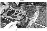
- FIG. 6 shows the console 1 in-use with suggested items staged using the cover 20.
- the cover 20 may be fitted with additional accessories, such as a rod holder 130.
- the rod holder 130 and fitting 135 may be mounted to the cover 20 using the apertures 24-27 preformed therein, or the cover 20 may be modified for mounting of the accessories.
- the cover 20 and console 1 provide an advantageous mounting location for accessories because of the central location and the substantially flat surface 22 provide by the cover 20.
- the storage compartment 10 under the cover 20 also provides clearance for any mountings.
- the removability of the cover 20 also improves the ease of attaching mounted accessories to the cover 20.
- the cover 20 allows for convenient mounting of accessories without having to drill through the shell 103 of the kayak 100.
- FIG. 8A shows cover 20.
- FIG. 8B provides one example of an alternative cover 1020.
- FIG. 8C shows an example of yet another alternative cover 1120.
- the kayak 100 may be described as part of a kit that provides customizable storage and staging options for the kayak 100.
- the kit may provide customizable storage and staging options without including the kayak 100 itself as part of the kit.
- the kit may have at least two replaceable covers 20, 1020 that are interchangeable atop the console 1.
- the cover 20 may be described as having a first arrangement of apertures 24-27.
- the alternative covers 1020 and 1120 shown in FIGs. 8B and 8C may be described as having a second arrangement of apertures, the second arrangement being different than the first.
- the cover 20, 1020, 1120 presently forming the top of the storage compartment 10 may be referred to as the in-use cover.
Landscapes
- Life Sciences & Earth Sciences (AREA)
- Environmental Sciences (AREA)
- Chemical & Material Sciences (AREA)
- Engineering & Computer Science (AREA)
- Combustion & Propulsion (AREA)
- Mechanical Engineering (AREA)
- Ocean & Marine Engineering (AREA)
- Animal Husbandry (AREA)
- Biodiversity & Conservation Biology (AREA)
- Vehicle Step Arrangements And Article Storage (AREA)
Applications Claiming Priority (1)
| Application Number | Priority Date | Filing Date | Title |
|---|---|---|---|
| US14/689,839 US9511826B2 (en) | 2015-04-17 | 2015-04-17 | Kayak having reconfigurable center staging |
Publications (2)
| Publication Number | Publication Date |
|---|---|
| EP3088293A2 true EP3088293A2 (de) | 2016-11-02 |
| EP3088293A3 EP3088293A3 (de) | 2016-11-16 |
Family
ID=55755464
Family Applications (1)
| Application Number | Title | Priority Date | Filing Date |
|---|---|---|---|
| EP16165531.1A Withdrawn EP3088293A3 (de) | 2015-04-17 | 2016-04-15 | Kajak mit rekonfigurierbarer mittlerer arbeitsbrücke |
Country Status (4)
| Country | Link |
|---|---|
| US (1) | US9511826B2 (de) |
| EP (1) | EP3088293A3 (de) |
| AU (1) | AU2016202066A1 (de) |
| CA (1) | CA2926080A1 (de) |
Families Citing this family (1)
| Publication number | Priority date | Publication date | Assignee | Title |
|---|---|---|---|---|
| USD1103882S1 (en) * | 2024-01-22 | 2025-12-02 | Lifetime Products, Inc. | Kayak transom |
Family Cites Families (10)
| Publication number | Priority date | Publication date | Assignee | Title |
|---|---|---|---|---|
| US5092263A (en) | 1989-05-30 | 1992-03-03 | Hutchison Brett C | Boat utility platform and mounting clamp therefor |
| US5542589A (en) * | 1992-09-08 | 1996-08-06 | Mckee; Carl B. | Desk structure for vehicles |
| US6178912B1 (en) * | 1993-08-02 | 2001-01-30 | Old Town Canoe Company | Sit-on-top kayak with space efficient cockpit area |
| US5964177A (en) * | 1993-08-02 | 1999-10-12 | Old Town Canoe Co. | Sit-on-top kayak |
| US6401648B1 (en) * | 2000-08-11 | 2002-06-11 | John Abbenhouse | Kayak hatch cover |
| US6581538B2 (en) | 2001-05-08 | 2003-06-24 | Sorensen John D. "Jack' | Integrated safety accessory arrangement and components for users of personal watercraft |
| US6435126B1 (en) | 2001-07-10 | 2002-08-20 | Morton Frederick Burke | River craft with outboard seat |
| US7032531B1 (en) * | 2005-07-15 | 2006-04-25 | Caples Sean G | Kayak |
| US20080035047A1 (en) | 2006-08-08 | 2008-02-14 | Mcdonough Robert J | Hybrid kayak and canoe self-propelled watercraft |
| AU2009100192B4 (en) | 2009-03-02 | 2010-04-29 | Aquatic Holdings Limited | Rotational moulded kayak with integrally formed utility bin |
-
2015
- 2015-04-17 US US14/689,839 patent/US9511826B2/en not_active Expired - Fee Related
-
2016
- 2016-04-04 AU AU2016202066A patent/AU2016202066A1/en not_active Abandoned
- 2016-04-05 CA CA2926080A patent/CA2926080A1/en not_active Abandoned
- 2016-04-15 EP EP16165531.1A patent/EP3088293A3/de not_active Withdrawn
Non-Patent Citations (1)
| Title |
|---|
| None |
Also Published As
| Publication number | Publication date |
|---|---|
| CA2926080A1 (en) | 2016-10-17 |
| AU2016202066A1 (en) | 2016-11-03 |
| EP3088293A3 (de) | 2016-11-16 |
| US20160304166A1 (en) | 2016-10-20 |
| US9511826B2 (en) | 2016-12-06 |
Similar Documents
| Publication | Publication Date | Title |
|---|---|---|
| US6755145B2 (en) | Kayak paddle holder and cockpit tray | |
| US7650713B1 (en) | Fishing pole holding device | |
| US4681219A (en) | Accessory for bass fishing boat | |
| US10159233B2 (en) | Combination paddle shaft and fishing rod | |
| US8833289B2 (en) | Bracket for a PWC | |
| US8881668B2 (en) | Flush mount rod holder with pad eye | |
| US9511826B2 (en) | Kayak having reconfigurable center staging | |
| US9120536B2 (en) | Apparatus for mounting accessories to a personal watercraft | |
| US20080222941A1 (en) | Fishing apparatus | |
| US8783205B1 (en) | Personal watercraft sport fishing conversion system | |
| US20200288692A1 (en) | Mooring cleat fishing rod holder | |
| AU2019387111B2 (en) | Pet corral for kayak | |
| US7104003B2 (en) | Quick-release snag resistant fishing net retainer | |
| JP6889729B2 (ja) | 遮光システムを備えた透明で調節可能なカヤック | |
| US7343870B1 (en) | Combination boat hawse pipe and accessory tray | |
| JP3035445B2 (ja) | 支柱レンチとナットのためのデケット収納装置および方法 | |
| US9540073B1 (en) | Lightweight personal watercraft | |
| US10577066B1 (en) | Vessel handle and paddle clip | |
| US7281488B1 (en) | Seat for shallow draft floating watercraft | |
| US12089581B2 (en) | Fishing rod and equipment storage systems and methods for making and using same | |
| US20170118968A1 (en) | Wearable and Portable Fishing Bait Container with Aerator | |
| JP2022123265A (ja) | 釣り具支持具及び釣り具収納装置 | |
| US10053199B2 (en) | Multi-purpose collaspible personal watercraft | |
| US9663209B2 (en) | Multi-purpose collapsible personal watercraft | |
| US20180346073A1 (en) | Rope tender for watercraft |
Legal Events
| Date | Code | Title | Description |
|---|---|---|---|
| PUAI | Public reference made under article 153(3) epc to a published international application that has entered the european phase |
Free format text: ORIGINAL CODE: 0009012 |
|
| PUAL | Search report despatched |
Free format text: ORIGINAL CODE: 0009013 |
|
| 17P | Request for examination filed |
Effective date: 20160415 |
|
| AK | Designated contracting states |
Kind code of ref document: A2 Designated state(s): AL AT BE BG CH CY CZ DE DK EE ES FI FR GB GR HR HU IE IS IT LI LT LU LV MC MK MT NL NO PL PT RO RS SE SI SK SM TR |
|
| AX | Request for extension of the european patent |
Extension state: BA ME |
|
| AK | Designated contracting states |
Kind code of ref document: A3 Designated state(s): AL AT BE BG CH CY CZ DE DK EE ES FI FR GB GR HR HU IE IS IT LI LT LU LV MC MK MT NL NO PL PT RO RS SE SI SK SM TR |
|
| AX | Request for extension of the european patent |
Extension state: BA ME |
|
| RIC1 | Information provided on ipc code assigned before grant |
Ipc: B63B 35/71 20060101AFI20161010BHEP |
|
| STAA | Information on the status of an ep patent application or granted ep patent |
Free format text: STATUS: THE APPLICATION IS DEEMED TO BE WITHDRAWN |
|
| 18D | Application deemed to be withdrawn |
Effective date: 20170517 |