EP3088288A2 - Electric vehicle - Google Patents
Electric vehicle Download PDFInfo
- Publication number
- EP3088288A2 EP3088288A2 EP16165858.8A EP16165858A EP3088288A2 EP 3088288 A2 EP3088288 A2 EP 3088288A2 EP 16165858 A EP16165858 A EP 16165858A EP 3088288 A2 EP3088288 A2 EP 3088288A2
- Authority
- EP
- European Patent Office
- Prior art keywords
- battery case
- transmission member
- electric vehicle
- battery
- body frame
- Prior art date
- Legal status (The legal status is an assumption and is not a legal conclusion. Google has not performed a legal analysis and makes no representation as to the accuracy of the status listed.)
- Withdrawn
Links
Images



Classifications
-
- B—PERFORMING OPERATIONS; TRANSPORTING
- B60—VEHICLES IN GENERAL
- B60K—ARRANGEMENT OR MOUNTING OF PROPULSION UNITS OR OF TRANSMISSIONS IN VEHICLES; ARRANGEMENT OR MOUNTING OF PLURAL DIVERSE PRIME-MOVERS IN VEHICLES; AUXILIARY DRIVES FOR VEHICLES; INSTRUMENTATION OR DASHBOARDS FOR VEHICLES; ARRANGEMENTS IN CONNECTION WITH COOLING, AIR INTAKE, GAS EXHAUST OR FUEL SUPPLY OF PROPULSION UNITS IN VEHICLES
- B60K1/00—Arrangement or mounting of electrical propulsion units
- B60K1/04—Arrangement or mounting of electrical propulsion units of the electric storage means for propulsion
-
- B—PERFORMING OPERATIONS; TRANSPORTING
- B60—VEHICLES IN GENERAL
- B60L—PROPULSION OF ELECTRICALLY-PROPELLED VEHICLES; SUPPLYING ELECTRIC POWER FOR AUXILIARY EQUIPMENT OF ELECTRICALLY-PROPELLED VEHICLES; ELECTRODYNAMIC BRAKE SYSTEMS FOR VEHICLES IN GENERAL; MAGNETIC SUSPENSION OR LEVITATION FOR VEHICLES; MONITORING OPERATING VARIABLES OF ELECTRICALLY-PROPELLED VEHICLES; ELECTRIC SAFETY DEVICES FOR ELECTRICALLY-PROPELLED VEHICLES
- B60L50/00—Electric propulsion with power supplied within the vehicle
- B60L50/50—Electric propulsion with power supplied within the vehicle using propulsion power supplied by batteries or fuel cells
- B60L50/60—Electric propulsion with power supplied within the vehicle using propulsion power supplied by batteries or fuel cells using power supplied by batteries
- B60L50/66—Arrangements of batteries
-
- B—PERFORMING OPERATIONS; TRANSPORTING
- B62—LAND VEHICLES FOR TRAVELLING OTHERWISE THAN ON RAILS
- B62J—CYCLE SADDLES OR SEATS; AUXILIARY DEVICES OR ACCESSORIES SPECIALLY ADAPTED TO CYCLES AND NOT OTHERWISE PROVIDED FOR, e.g. ARTICLE CARRIERS OR CYCLE PROTECTORS
- B62J13/00—Guards for chain, chain drive or equivalent drive, e.g. belt drive
- B62J13/02—Guards for chain, chain drive or equivalent drive, e.g. belt drive shielding only the upper run of the chain or the like
-
- B—PERFORMING OPERATIONS; TRANSPORTING
- B62—LAND VEHICLES FOR TRAVELLING OTHERWISE THAN ON RAILS
- B62J—CYCLE SADDLES OR SEATS; AUXILIARY DEVICES OR ACCESSORIES SPECIALLY ADAPTED TO CYCLES AND NOT OTHERWISE PROVIDED FOR, e.g. ARTICLE CARRIERS OR CYCLE PROTECTORS
- B62J43/00—Arrangements of batteries
- B62J43/10—Arrangements of batteries for propulsion
- B62J43/16—Arrangements of batteries for propulsion on motorcycles or the like
-
- B—PERFORMING OPERATIONS; TRANSPORTING
- B62—LAND VEHICLES FOR TRAVELLING OTHERWISE THAN ON RAILS
- B62K—CYCLES; CYCLE FRAMES; CYCLE STEERING DEVICES; RIDER-OPERATED TERMINAL CONTROLS SPECIALLY ADAPTED FOR CYCLES; CYCLE AXLE SUSPENSIONS; CYCLE SIDECARS, FORECARS, OR THE LIKE
- B62K11/00—Motorcycles, engine-assisted cycles or motor scooters with one or two wheels
- B62K11/02—Frames
- B62K11/04—Frames characterised by the engine being between front and rear wheels
-
- B—PERFORMING OPERATIONS; TRANSPORTING
- B62—LAND VEHICLES FOR TRAVELLING OTHERWISE THAN ON RAILS
- B62K—CYCLES; CYCLE FRAMES; CYCLE STEERING DEVICES; RIDER-OPERATED TERMINAL CONTROLS SPECIALLY ADAPTED FOR CYCLES; CYCLE AXLE SUSPENSIONS; CYCLE SIDECARS, FORECARS, OR THE LIKE
- B62K25/00—Axle suspensions
- B62K25/04—Axle suspensions for mounting axles resiliently on cycle frame or fork
- B62K25/28—Axle suspensions for mounting axles resiliently on cycle frame or fork with pivoted chain-stay
- B62K25/283—Axle suspensions for mounting axles resiliently on cycle frame or fork with pivoted chain-stay for cycles without a pedal crank, e.g. motorcycles
-
- B—PERFORMING OPERATIONS; TRANSPORTING
- B62—LAND VEHICLES FOR TRAVELLING OTHERWISE THAN ON RAILS
- B62M—RIDER PROPULSION OF WHEELED VEHICLES OR SLEDGES; POWERED PROPULSION OF SLEDGES OR SINGLE-TRACK CYCLES; TRANSMISSIONS SPECIALLY ADAPTED FOR SUCH VEHICLES
- B62M7/00—Motorcycles characterised by position of motor or engine
- B62M7/02—Motorcycles characterised by position of motor or engine with engine between front and rear wheels
-
- B—PERFORMING OPERATIONS; TRANSPORTING
- B62—LAND VEHICLES FOR TRAVELLING OTHERWISE THAN ON RAILS
- B62M—RIDER PROPULSION OF WHEELED VEHICLES OR SLEDGES; POWERED PROPULSION OF SLEDGES OR SINGLE-TRACK CYCLES; TRANSMISSIONS SPECIALLY ADAPTED FOR SUCH VEHICLES
- B62M9/00—Transmissions characterised by use of an endless chain, belt, or the like
- B62M9/16—Tensioning or adjusting equipment for chains, belts or the like
-
- B—PERFORMING OPERATIONS; TRANSPORTING
- B62—LAND VEHICLES FOR TRAVELLING OTHERWISE THAN ON RAILS
- B62K—CYCLES; CYCLE FRAMES; CYCLE STEERING DEVICES; RIDER-OPERATED TERMINAL CONTROLS SPECIALLY ADAPTED FOR CYCLES; CYCLE AXLE SUSPENSIONS; CYCLE SIDECARS, FORECARS, OR THE LIKE
- B62K2204/00—Adaptations for driving cycles by electric motor
-
- Y—GENERAL TAGGING OF NEW TECHNOLOGICAL DEVELOPMENTS; GENERAL TAGGING OF CROSS-SECTIONAL TECHNOLOGIES SPANNING OVER SEVERAL SECTIONS OF THE IPC; TECHNICAL SUBJECTS COVERED BY FORMER USPC CROSS-REFERENCE ART COLLECTIONS [XRACs] AND DIGESTS
- Y02—TECHNOLOGIES OR APPLICATIONS FOR MITIGATION OR ADAPTATION AGAINST CLIMATE CHANGE
- Y02T—CLIMATE CHANGE MITIGATION TECHNOLOGIES RELATED TO TRANSPORTATION
- Y02T10/00—Road transport of goods or passengers
- Y02T10/60—Other road transportation technologies with climate change mitigation effect
- Y02T10/70—Energy storage systems for electromobility, e.g. batteries
Definitions
- the present invention relates to an electric vehicle, and in particular, though not exclusively, to a straddled electric vehicle.
- the movement restriction member 9 has an arm 92 mounted on the vehicle body frame 2 and the touch portion 94 supported by the arm 92.
- the touch portion 94 is a chain roller supported so as to rotate on the lower end portion of the arm 92, for example. This, however, is not limiting, and the touch portion 94 may be a chain slider fixed to the lower end portion of the arm 92, for example.
- the touch portion 94 can be made of rubber, for example.
- the movement restriction member 9 is provided to advantageously prevent the transmission member 72 from touching the connection portion 30c of the motor case 30.
- This can increase freedom in layout. That is, without restriction due to touch between the transmission member 72 and the connection portion 30c of the motor case 30, it is possible to reduce the front-back length of the electric vehicle 1, to enlarge the battery 23 in the front-back direction in order to ensure a larger capacity, and to mount the battery 23 in a lower position to ensure low barycenter. Further, it is not necessary to limit the movement range of the swing arm 7.
Landscapes
- Engineering & Computer Science (AREA)
- Mechanical Engineering (AREA)
- Transportation (AREA)
- Chemical & Material Sciences (AREA)
- Combustion & Propulsion (AREA)
- Life Sciences & Earth Sciences (AREA)
- Sustainable Development (AREA)
- Sustainable Energy (AREA)
- Power Engineering (AREA)
- Arrangement Or Mounting Of Propulsion Units For Vehicles (AREA)
- Axle Suspensions And Sidecars For Cycles (AREA)
- Automatic Cycles, And Cycles In General (AREA)
Abstract
Description
- The present invention relates to an electric vehicle, and in particular, though not exclusively, to a straddled electric vehicle.
-
WO2013/061484 (KAWASAKI) discloses an electric motorcycle having a battery case for storing a battery, positioned near the middle of the motorcycle in the front-back direction. Similar to a typical motorcycle, the electric motorcycle has a swing arm that is supported so as to swing relative to a vehicle body frame and that transmits a driving force to the rear wheel via an endless transmission member such as a chain, or the like. - In the electric motorcycle disclosed in
WO2013/061484 , in order to ensure a range of movement of the transmission member that moves following the up-down movement of the swing arm, it is necessary to ensure clearance by mounting the battery case far ahead of or above the transmission member. This makes it difficult to achieve size reduction. In reality, according toWO2013/061484 , the battery case is mounted so as to be displaced in the forward direction relative to the motor case, and this results in a vehicle that is relatively long. - It is possible to seek to ensure clearance between the battery case and the transmission member by limiting the movement range of the swing arm by limiting the expansion and contraction amount of the suspension. In this case, however, riding comfort may deteriorate. Still further, it is possible to ensure clearance between the battery case and the transmission member by reducing the size of the battery case. In this case, however, decreased capacity of the battery and thus a shorter traveling distance may result.
- The present invention has been conceived in view of the above, and aims to seek to provide an electric vehicle of which a size is reduced without deterioration of riding comfort and/or battery capacity.
- It is an object of at least one embodiment of at least one aspect of the present invention to obviate or at least mitigate one or more problems or disadvantages in the prior art.
- Various aspects of the present invention are defined in the independent claims appended hereto. Some optional and/or preferred features are defined in the dependent claims appended hereto.
- According to an aspect of the present invention there is provided an electric vehicle.
- The electric vehicle may comprise a vehicle body frame.
- The electric vehicle may comprise a swing arm which may be supported on the vehicle body frame, for example, via a pivot shaft so as to swing in an up-down direction.
- The electric vehicle may comprise a rear wheel supported on the swing arm.
- The electric vehicle may comprise an electric motor.
- The electric vehicle may comprise an output shaft to which a driving force of the electric motor may be transmitted.
- The electric vehicle may comprise an endless transmission member, for example, for transmitting a driving force outputted from the output shaft to the rear wheel.
- The electric vehicle may comprise a battery, for example, for supplying power to the electric motor.
- The electric vehicle may comprise a battery case, for example, for storing the battery.
- The output shaft may be positioned lower than the lower end of the battery case and/or more forward than the rear end of the battery case in a side view.
- A movement restriction member that may touch the transmission member to thereby restrict upward movement of the transmission member may be mounted on the vehicle body frame or a member fixed to the vehicle body frame.
- According to the present invention, even in the case where the output shaft may be positioned lower than the lower end of the battery case and more forward than the rear end of the battery case in a side view, as the movement restriction member may be provided, it is possible to prevent the battery case from touching the transmission member. This may make it possible to reduce the size without deteriorating the riding comfortable and/or the battery capacity. The pivot shaft may be positioned lower than the lower end of the battery case and/or more forward than the rear end of the battery in a side view.
- The transmission member and the battery case may at least partially overlap to each other in a plan view.
- The movement restriction member may touch the transmission member at a position more rearward than the rear end of the battery case.
- The electric vehicle may further comprise a suspension which may be positioned between the vehicle body frame and the swing arm.
- The movement restriction member may touch the transmission member, for example, at least when the suspension may be in a most contracted state.
- The movement restriction member may be positioned lower than the battery case in a circumferential direction with the output shaft as a center.
- The vehicle body frame may include a rear frame which may be diagonally extending rearward and upward from a position behind the battery case.
- The movement restriction member may be mounted on a front end portion of the rear frame.
- The movement restriction member may be mounted on the battery case.
- The electric vehicle may further comprise a motor case for storing the electric motor. A lower edge of the battery case and an upper edge of the motor case may be put together or may be adjacent to or in abutment with one another.
- The electric vehicle may further comprise a motor case for storing the electric motor. A recess may be formed on the motor case, for example, so as to be opened at least downward. The transmission member may be positioned inside the recess.
- The electric vehicle preferably may be a straddled vehicle, such as a motorcycle or bicycle.
- It will be appreciated that features analogous to those described in relation to any of the above aspects may be individually and separably or in combination applicable to any of the other aspects.
- An embodiment of the present invention will now be described, by way of example only, with reference to the accompanying drawings, which are:
- Figure 1
- a side view of an electric vehicle according to an embodiment of the present invention;
- Figure 2
- a side view showing enlarged a major part of the electric vehicle of
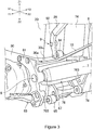
Figure 1 ; - Figure 3
- a perspective view showing enlarged a major part of the electric vehicle of
Figure 1 ; and - Figure 4
- a cross-sectional view of a major part of the electric vehicle of
Figure 1 . - An embodiment of the present invention will now be described with reference to the accompanying drawings.
-
Figure 1 is a side view of anelectric vehicle 1 according to one embodiment of the present invention.Figure 2 is a side view showing enlarged an area near apivot shaft 6 of theelectric vehicle 1.Figure 3 is a perspective view showing an area near thepivot shaft 6 of theelectric vehicle 1 viewed from the left rear side thereof.Figure 4 is a cross-sectional view along the line IV-IV shown inFigure 2 . Note that X1 and X2 shown in the respective diagrams indicate the forward and rearward directions, respectively; Y1 and Y2 indicate the leftward and rightward directions, respectively; and Z1 and Z2 indicate the upward and downward directions, respectively. - In the drawings, a
swing arm 7 and arear wheel 8 with asuspension 74 in the most contracted state are shown. InFigure 1 , theswing arm 7 and therear wheel 8 with thesuspension 74 in an unloaded state are indicated by the long dashed double-short dashed line. - In this embodiment the
electric vehicle 1 is a straddled electric vehicle, for example. In the following, an electric motorcycle will be described as one example of a straddled electric vehicle. This, however, is not limiting, and theelectric vehicle 1 may be an electric automobile, such as a rough terrain vehicle, for example. - The
electric vehicle 1 has a monocoque vehicle body frame 2, for example. Ahead pipe 21 is mounted on the front portion of the vehicle body frame 2, and afront fork 3 is supported on thehead pipe 21 so as to rotate in the left-right direction. A front wheel 4 is mounted on the lower portion of thefront fork 3, and ahandle 5 for steering is mounted on the upper portion of thefront fork 3. Apivot shaft 6 is mounted below the vehicle body frame 2, and aswing arm 7 is supported on the lower portion of thepivot shaft 6 so as to swing in the up-down direction. Arear wheel 8 is supported on the rear portion of theswing arm 7. - The
electric vehicle 1 has anelectric motor 31 as a power source for generating a driving force for driving therear wheel 8, and abattery 23 as an energy source for supplying power to theelectric motor 31. A lithium ion battery, for example, is preferable as thebattery 23. The driving force of theelectric motor 31 is decelerated by adecelerator 33 before being transmitted to anoutput shaft 35 and further to therear wheel 8 via atransmission member 72 such as a chain, a belt or the like. - The
battery 23 is stored in abattery case 20 provided below, e.g. (at least partly) directly below, theseat 29. Thebattery case 20 constitutes a part of the vehicle body frame 2. Thebattery case 20 has a box shape that is opened upward, and acover 25 that can be opened and closed is attached to the upper portion of thebattery case 20. When theseat 29 is removed and thecover 25 is opened, it is possible to access the inside of thebattery case 20. - In this embodiment, the
battery 23 is demounted from thebattery case 20 and charged by an external charger. In this embodiment, a plurality ofbatteries 23 are stored in thebattery case 20. The size and weight of eachbattery 23 is designed appropriate to be carried manually. With the above arrangement, easiness in manually carrying thebattery 23 and an output and capacity necessary for theelectric vehicle 1 to run are both ensured. - Behind the
battery case 20, an upperrear frame 27 and a lowerrear frame 28 are mounted. The upperrear frame 27 is connected to the upper portion of the rear surface of thebattery case 20, while the lowerrear frame 28 is connected to the lower portion of the rear surface of thebattery case 20. In detail, the lowerrear frame 28 is connected to thebattery case 20 via anarm 92 of amovement restriction member 9 to be described later. This, however, is not limiting, and the lowerrear frame 28 may be directly connected to thebattery case 20 or connected to other frame member. - Below the
battery case 20, amotor case 30 for storing theelectric motor 31, thedecelerator 33, and theoutput shaft 35 is mounted. In themotor case 30, amotor control unit 39 for controlling the power supplied from thebattery 23 to theelectric motor 31 is stored. Theelectric motor 31 is positioned at the middle of themotor case 30 in the front-back direction. Themotor control unit 39 is positioned ahead of theelectric motor 31. Theoutput shaft 35 is positioned behind theelectric motor 31. Thebattery case 20 and themotor case 30 are made of a metallic based material such as aluminum, iron, magnesium, or alloy of any thereof, for example. - The
motor case 30 has a box shape that is opened upward, and is connected to the lower end portion of thebattery case 20. Specifically, the upper edge of themotor case 30 has a shape in accordance with the lower edge of thebattery case 20, and the lower edge of thebattery case 20 and the upper edge of themotor case 30 are put or abutted together and fixed to each other by a fixing means, such as ascrew 203 in the inside of thebattery case 20. With the above, as theelectric motor 31 or the like stored in themotor case 30 is positioned below, i.e. directly below, thebattery case 20; it is thereby possible to achieve size reduction of theelectric vehicle 1 in the front-back direction. - As shown in
Figures 1 and2 , theoutput shaft 35 is positioned lower than the lower end of thebattery case 20 and more forward than the rear end of thebattery case 20 in a side view. On the left end portion of theoutput shaft 35 that is exposed outside themotor case 30, a drivingside rotating member 37, such as a sprocket, a pulley, or the like, for transmitting a driving force of theoutput shaft 35 to anendless transmission member 72, such as a chain, a belt, or the like, is mounted. - On the left surface and the right surface of the
motor case 30, a pair ofbrackets 61 are mounted, and thepivot shaft 6 is mounted in a position between the pair of left andright brackets 61 behind themotor case 30. Thebracket 61 has a substantial U-shape that projects rearward, and is fixed to the side surface of themotor case 30 on the upper and lower portions thereof by a screw or the like. The portion projecting rearward of thebracket 61 is connected to thepivot shaft 6. Further, afootrest 63 is mounted on the lower portion of thebracket 61. - As shown in
Figures 1 and2 , thepivot shaft 6 is also positioned lower than the lower end of thebattery case 20 more forward than the rear end of thebattery case 20 in a side view. Thepivot shaft 6 is positioned behind theoutput shaft 35 in a side view such that the upper portion and lower portion of thebracket 61 sandwich theoutput shaft 35 in the up-down direction in a side view. Thebracket 61 mounted on the left side surface of themotor case 30 is positioned more leftward than the drivingside rotating member 37 and thetransmission member 72. - On the
pivot shaft 6, the front end portion of theswing arm 7 is supported so as to rotate so that theswing arm 7 can swing in the up-down direction with thepivot shaft 6 as the center. Thesuspension 74 is present between the vehicle body frame 2 and theswing arm 7. In this embodiment, thesuspension 74 is positioned behind thebattery case 20 and can extract or contract in the up-down direction. The upper end portion of thesuspension 74 is connected to the upperrear frame 27, while the lower end portion of the same is connected to theswing arm 7 via alink 78. - The
endless transmission member 72 is wound around the drivingside rotating member 37 mounted on theoutput shaft 35 and a followingside rotating member 81, such as a sprocket, a pulley, or the like, mounted on therear wheel 8. A driving force from theoutput shaft 35 is transmitted from the drivingside rotating member 37 mounted on theoutput shaft 35 to thetransmission member 72 and further to the followingside rotating member 81, and therear wheel 8 resultantly rotates. Thetransmission member 72 swings in the up-down direction together with theswing arm 7. - As shown in
Figures 2 and4 , thetransmission member 72 is positioned so as to travel below the lower left rear portion of thebattery case 20. In this embodiment, theentire transmission member 72 in the left-right direction is fully overlapped by thebattery case 20 in a plan view. With this, it is possible to reduce the size of theelectric vehicle 1 in the left-right direction. This, however, is not limiting, and only a part of thetransmission member 72 in the left-right direction may be overlapped by thebattery case 20 in a plan view. - Further, a
recess 30a is formed on the upper left rear portion of themotor case 30 so as to be opened downward and leftward. Thetransmission member 72 is positioned in therecess 30a. Therecess 30a is formed so that thetransmission member 72 does not touch themotor case 30. Specifically, therecess 30a is formed so that thetransmission member 72 when having moved upward to touch a (touch)portion 94 of the movement restriction member 9 (to be described later) does not touch a part above therecess 30a. The part above therecess 30a corresponds to aconnection portion 30c that is connected to the lower left rear end portion of thebattery case 20. - A substantially U-shaped seal guard 76 - which sandwiches the
swing arm 7 in the up-down direction - is supported on thepivot shaft 6 so as to swing in the up-down direction. Theseal guard 76 has a pair ofarms like shaft portion 765 and extending rearward, the ring-like shaft portion 765 being supported so as to rotate on thepivot shaft 6. Thearms swing arm 7 near thepivot shaft 6 to thereby prevent thetransmission member 72 from directly touching theswing arm 7. - Below the
seal guard 76, achain roller 65 for preventing thetransmission member 72 from deflecting is mounted. Thechain roller 65 is positioned behind and below thepivot shaft 6 in a side view, and fixed to themotor case 30 via abracket 67. Thechain roller 65 touches thetransmission member 72 to apply tension when theswing arm 7 is on or near a straight line connecting theoutput shaft 35 and thepivot shaft 6. While theswing arm 7 is going to the highest position (the position where thesuspension 74 is in the most contracted state), thechain roller 65 departs from thetransmission member 72. - In this embodiment, the
output shaft 35 is positioned lower than the lower end of thebattery case 20 and more forward than the rear end of the same in a side view, as described above. Therefore, it is necessary to ensure clearance between thetransmission member 72 that swings in the up-down direction together with theswing arm 7 and the lower left rear end portion of thebattery case 20. However, in an attempt to reduce further the size of the front-back length of theelectric vehicle 1, to enlarge thebattery 23 in the front-back direction in order to ensure larger capacity, or to mount thebattery 23 in a lower position to ensure lower barycenter, this clearance tends to decrease. - In view of the above, in this embodiment, the
movement restriction member 9 to be described later is provided to prevent thetransmission member 72 swinging in the up-down direction from touching the lower left rear end portion of thebattery case 20 or theconnection portion 30c of themotor case 30 connected to the lower left rear end portion. Note that the description below is focused on theconnection portion 30c of themotor case 30 connected to the lower left rear end portion of thebattery case 20. - The
movement restriction member 9 has anarm 92 mounted on the vehicle body frame 2 and thetouch portion 94 supported by thearm 92. Thetouch portion 94 is a chain roller supported so as to rotate on the lower end portion of thearm 92, for example. This, however, is not limiting, and thetouch portion 94 may be a chain slider fixed to the lower end portion of thearm 92, for example. Thetouch portion 94 can be made of rubber, for example. - The
arm 92 is mounted on the front end portion of the lowerrear frame 28 and extends downward. Thearm 92 is mounted also on the lower portion of the rear surface of thebattery case 20 so as to be present between the lowerrear frame 28 and thebattery case 20. Specifically, the upper end portion of thearm 92 is fixed to the front end portion of the lowerrear frame 28 by means of welding or the like, and a middle portion of thearm 92 is fixed to abracket 201 mounted on the lower portion of the rear surface of thebattery case 20 by a screw or the like. Thearm 92 is mounted on the vehicle body frame 2 or a member fixed to the vehicle body frame 2. That is, thearm 92 is fixed to a member that does not swing relative to the vehicle body frame 2. - The position where the
arm 92 is mounted is not limited to any particular position, as long as the position allows thetouch portion 94 to be positioned so as to prevent thetransmission member 72 from touching theconnection portion 30c of themotor case 30. For example, thearm 92 may be mounted on a middle portion or rear end portion of the lowerrear frame 28 or on the upperrear frame 27. Alternatively, thearm 92 may be mounted alone on thebattery case 20. In the case where thebattery case 20 does not constitute a part of the vehicle body frame 2, thearm 92 can be mounted on thebattery case 20. - The
touch portion 94 touches thetransmission member 72 to thereby locally restrict upward movement of thetransmission member 72, and further to prevent thetransmission member 72 from touching theconnection portion 30c of themotor case 30. - The
touch portion 94 touches thetransmission member 72 in a position more rearward than the rear end of thebattery case 20. Thetouch portion 94 is positioned more rearward than the rear end of thebattery case 20 and more forward than therear wheel 8. In order to prevent touch between thetransmission member 72 and theconnection portion 30c of themotor case 30, it is preferable that thetouch portion 94 is positioned near the rear end of thebattery case 20. For example, thetouch portion 94 may be positioned more forward than the rear end of theseal guard 76 or positioned overlapping thesuspension 74 in a side view. Note that thetouch portion 94 may be positioned more forward than the rear end of thebattery case 20 and lower than the lower end of the same. However, in order to ensure lower barycenter, it is preferable that thetouch portion 94 is positioned more rearward than the rear end of thebattery case 20. - At least when the
swing arm 7 is at the highest position (the position where thesuspension 74 is in the most contracted state), thetouch portion 94 touches thetransmission member 72. For example, thetouch portion 94 touches thetransmission member 72 only when theswing arm 7 is in the highest position or a position near the highest position, and does not touch thetransmission member 72 when theswing arm 7 is positioned lower than the highest position. With the above, as thetouch portion 94 does not touch thetransmission member 72 in a normal state in which a relatively large load is not applied to thesuspension 74, it is possible to prevent abrasion of thetouch portion 94. This, however, is not limiting, and thetouch portion 94 may touch thetransmission member 72 in a normal state. - The
touch portion 94 is positioned so as to touch thetransmission member 72 prior to theconnection portion 30c of themotor case 30 while theswing arm 7 is moving upward. For example, thetouch portion 94 is positioned lower than theconnection portion 30c of themotor case 30 in the circumferential direction with the output shaft 35 (or the upper end of the driving side rotating member 37) as the center. Further, thetouch portion 94 may be positioned higher than the lower end of thebattery case 20 as long as thetouch portion 94 touches thetransmission member 72 prior to thebattery case 20 while theswing arm 7 is moving upward. - Further, it is preferable that the
touch portion 94 does not simultaneously touch thetransmission member 72 with thechain roller 65. That is, it is preferable that thetouch portion 94 touches thetransmission member 72 after thechain roller 65 departs from thetransmission member 72 while theswing arm 7 is moving upward. With the above, it is beneficially possible to prevent excessive increase of the tension of thetransmission member 72 due to thechain roller 65 and thetouch portion 94 simultaneously touching thetransmission member 72. - As described above, in this embodiment, the
movement restriction member 9 is provided to advantageously prevent thetransmission member 72 from touching theconnection portion 30c of themotor case 30. This can increase freedom in layout. That is, without restriction due to touch between thetransmission member 72 and theconnection portion 30c of themotor case 30, it is possible to reduce the front-back length of theelectric vehicle 1, to enlarge thebattery 23 in the front-back direction in order to ensure a larger capacity, and to mount thebattery 23 in a lower position to ensure low barycenter. Further, it is not necessary to limit the movement range of theswing arm 7. - Although an embodiment of the present invention has been described in the above, the present invention is not limited to the above described embodiment, and various modified embodiments are possible for a person skilled in the art.
- It will be appreciated that the embodiment of the present invention hereinbefore described is given by way of example only, and is not intended to limit the scope of the invention in any way.
- It will be appreciated that the term straddled vehicle or motor vehicle used herein, and as used in the art, is meant to include the following terms also used in the art:
- straddle-type vehicle or motor vehicle, saddle-ride type vehicle or motor vehicle, saddle-straddling type vehicle or motor vehicle, and includes: motorcycles and motorbikes as well as motor tricycles, quadbikes, All Terrain Vehicles (ATVs), scooters, mopeds and snowmobiles.
Claims (10)
- An electric vehicle (1) comprising:a vehicle body frame (2),a swing arm (7) supported on the vehicle body frame via a pivot shaft (6) so as to swing in an up-down direction,a rear wheel (8) supported on the swing arm,an electric motor (31),an output shaft (35) to which a driving force of the electric motor is transmitted,an endless transmission member (72) for transmitting a driving force outputted from the output shaft to the rear wheel,a battery (23) for supplying power to the electric motor, anda battery case (20) for storing the battery, whereinthe output shaft is positioned lower than a lower end of the battery case and more forward than a rear end of the battery case in a side view, anda movement restriction member (9) for touching the transmission member to restrict upward movement of the transmission member is mounted on the vehicle body frame or a member fixed to the vehicle body frame.
- The electric vehicle according to claim 1, wherein the pivot shaft is positioned lower than the lower end of the battery case and more forward than the rear end of the battery in a side view.
- The electric vehicle according to any preceding claim, wherein the transmission member and the battery case at least partially overlap each other in a plan view.
- The electric vehicle according to any preceding claim, wherein the movement restriction member touches the transmission member at a position more rearward than the rear end of the battery case.
- The electric vehicle according to any preceding claim, further comprising a suspension positioned between the vehicle body frame and the swing arm, wherein
the movement restriction member touches the transmission member at least when the suspension is in a most contracted state. - The electric vehicle according to any preceding claim, wherein the movement restriction member is positioned lower than the battery case in a circumferential direction with the output shaft as a center.
- The electric vehicle according to any preceding claim, wherein
the vehicle body frame includes a rear frame diagonally extending rearward and upward from a position behind the battery case, and
the movement restriction member is mounted on a front end portion of the rear frame. - The electric vehicle according to any preceding claim, wherein the movement restriction member is mounted on the battery case.
- The electric vehicle according to any preceding claim, further comprising:a motor case (30) for storing the electric motor, whereina lower edge of the battery case and an upper edge of the motor case are put together or arranged in abutment with one another or placed together in intimate contact.
- The electric vehicle according to any preceding claim, further comprising:a motor case for storing the electric motor, whereina recess (30a) is formed on the motor case so as to be opened at least downward, andthe transmission member is positioned inside the recess.
Applications Claiming Priority (1)
| Application Number | Priority Date | Filing Date | Title |
|---|---|---|---|
| JP2015092146A JP2016203954A (en) | 2015-04-28 | 2015-04-28 | Electric vehicle |
Publications (2)
| Publication Number | Publication Date |
|---|---|
| EP3088288A2 true EP3088288A2 (en) | 2016-11-02 |
| EP3088288A3 EP3088288A3 (en) | 2016-11-09 |
Family
ID=55759546
Family Applications (1)
| Application Number | Title | Priority Date | Filing Date |
|---|---|---|---|
| EP16165858.8A Withdrawn EP3088288A3 (en) | 2015-04-28 | 2016-04-18 | Electric vehicle |
Country Status (3)
| Country | Link |
|---|---|
| US (1) | US20160318579A1 (en) |
| EP (1) | EP3088288A3 (en) |
| JP (1) | JP2016203954A (en) |
Cited By (3)
| Publication number | Priority date | Publication date | Assignee | Title |
|---|---|---|---|---|
| EP3677495A1 (en) * | 2019-01-07 | 2020-07-08 | Harley-Davidson Motor Company Group, LLC | Swingarm concentric motor drive for electric motorcycle |
| EP4311753A1 (en) * | 2022-07-25 | 2024-01-31 | Kawasaki Motors, Ltd. | Straddle electric vehicle |
| US12534151B2 (en) | 2023-03-08 | 2026-01-27 | Livewire Ev, Llc | Electric motorcycle |
Families Citing this family (16)
| Publication number | Priority date | Publication date | Assignee | Title |
|---|---|---|---|---|
| US10632857B2 (en) | 2016-08-17 | 2020-04-28 | Shape Corp. | Battery support and protection structure for a vehicle |
| CN110383526A (en) | 2017-01-04 | 2019-10-25 | 形状集团 | Node Modular Vehicle Battery Tray Structure |
| WO2018213383A1 (en) | 2017-05-16 | 2018-11-22 | Shape Corp. | Vehicle battery tray with integrated battery retention and support features |
| US10483510B2 (en) | 2017-05-16 | 2019-11-19 | Shape Corp. | Polarized battery tray for a vehicle |
| US10886513B2 (en) | 2017-05-16 | 2021-01-05 | Shape Corp. | Vehicle battery tray having tub-based integration |
| CN111108015A (en) | 2017-09-13 | 2020-05-05 | 形状集团 | Vehicle battery tray with tubular peripheral wall |
| US12347879B2 (en) | 2017-09-13 | 2025-07-01 | Shape Corp. | Vehicle battery tray with tubular peripheral wall |
| WO2019071013A1 (en) | 2017-10-04 | 2019-04-11 | Shape Corp. | Battery tray floor assembly for electric vehicles |
| EP3759761B1 (en) | 2018-03-01 | 2026-04-08 | Shape Corp. | Cooling system integrated with vehicle battery tray |
| US11688910B2 (en) | 2018-03-15 | 2023-06-27 | Shape Corp. | Vehicle battery tray having tub-based component |
| WO2020012791A1 (en) * | 2018-07-13 | 2020-01-16 | 本田技研工業株式会社 | Vehicle body frame structure for saddle-type electric vehicle |
| JP7714467B2 (en) * | 2019-03-05 | 2025-07-29 | クーデル・ソシエテ・アノニム | System and method for controlling the attitude of a vehicle, and a vehicle equipped with the system |
| US12485981B2 (en) | 2021-03-24 | 2025-12-02 | Polaris Industries Inc. | Electric recreational vehicle |
| CN217074654U (en) * | 2021-09-28 | 2022-07-29 | 浙江春风动力股份有限公司 | All-terrain vehicle |
| TWI842096B (en) * | 2022-09-19 | 2024-05-11 | 光陽工業股份有限公司 | Electric motorcycle inertia sensing device |
| CN118977797A (en) | 2023-05-15 | 2024-11-19 | 川崎摩托株式会社 | Saddle-type vehicle and coupling bracket used for the saddle-type vehicle |
Citations (1)
| Publication number | Priority date | Publication date | Assignee | Title |
|---|---|---|---|---|
| WO2013061484A1 (en) | 2011-10-28 | 2013-05-02 | 川崎重工業株式会社 | Saddle-type electric vehicle |
Family Cites Families (13)
| Publication number | Priority date | Publication date | Assignee | Title |
|---|---|---|---|---|
| US4034821A (en) * | 1976-06-09 | 1977-07-12 | Stoddard Richard B | Motorcycle chain drive |
| US4069719A (en) * | 1976-06-18 | 1978-01-24 | Cancilla Philip S | Chain tensioner for chain drives |
| JP4274759B2 (en) * | 2002-08-16 | 2009-06-10 | ヤマハ発動機株式会社 | Electric motorcycle |
| US7255191B2 (en) * | 2003-10-31 | 2007-08-14 | Vectrix Corporation | Composite construction vehicle frame |
| CN103140366B (en) * | 2010-11-12 | 2016-01-20 | 川崎重工业株式会社 | Mounting structure of power storage device for electric vehicle |
| WO2012066599A1 (en) * | 2010-11-18 | 2012-05-24 | 川崎重工業株式会社 | Electric two-wheeled vehicle |
| JP5715430B2 (en) * | 2011-02-02 | 2015-05-07 | 本田技研工業株式会社 | Sports-type saddle-ride type electric vehicle |
| JP2012186893A (en) * | 2011-03-04 | 2012-09-27 | Honda Motor Co Ltd | Electric vehicle |
| JP5643687B2 (en) * | 2011-03-15 | 2014-12-17 | 本田技研工業株式会社 | Battery mounting structure for saddle-ride type electric vehicles |
| DE102011078265B3 (en) * | 2011-06-29 | 2012-06-21 | Bayerische Motoren Werke Aktiengesellschaft | Vehicle having a housing designed as a structural component structural component of an electrical energy storage |
| JP5727911B2 (en) * | 2011-09-28 | 2015-06-03 | 本田技研工業株式会社 | Rear structure of saddle-ride type vehicle |
| EP2772419A4 (en) * | 2011-10-26 | 2016-07-13 | Kawasaki Heavy Ind Ltd | ELECTRIC VEHICLE AND METHOD FOR DRIVING AN ELECTRIC VEHICLE |
| JP6245946B2 (en) * | 2013-11-06 | 2017-12-13 | ヤマハ発動機株式会社 | Battery and saddle riding type electric vehicle equipped with the same |
-
2015
- 2015-04-28 JP JP2015092146A patent/JP2016203954A/en active Pending
-
2016
- 2016-04-18 EP EP16165858.8A patent/EP3088288A3/en not_active Withdrawn
- 2016-04-22 US US15/135,602 patent/US20160318579A1/en not_active Abandoned
Patent Citations (1)
| Publication number | Priority date | Publication date | Assignee | Title |
|---|---|---|---|---|
| WO2013061484A1 (en) | 2011-10-28 | 2013-05-02 | 川崎重工業株式会社 | Saddle-type electric vehicle |
Cited By (6)
| Publication number | Priority date | Publication date | Assignee | Title |
|---|---|---|---|---|
| EP3677495A1 (en) * | 2019-01-07 | 2020-07-08 | Harley-Davidson Motor Company Group, LLC | Swingarm concentric motor drive for electric motorcycle |
| US11260934B2 (en) | 2019-01-07 | 2022-03-01 | Harley-Davidson Motor Company Group, LLC | Swingarm concentric motor drive for electric motorcycle |
| US11708126B2 (en) | 2019-01-07 | 2023-07-25 | Livewire Ev, Llc | Swingarm concentric motor drive for electric motorcycle |
| US12122476B2 (en) | 2019-01-07 | 2024-10-22 | Livewire Ev, Llc | Swingarm concentric motor drive for electric motorcycle |
| EP4311753A1 (en) * | 2022-07-25 | 2024-01-31 | Kawasaki Motors, Ltd. | Straddle electric vehicle |
| US12534151B2 (en) | 2023-03-08 | 2026-01-27 | Livewire Ev, Llc | Electric motorcycle |
Also Published As
| Publication number | Publication date |
|---|---|
| JP2016203954A (en) | 2016-12-08 |
| US20160318579A1 (en) | 2016-11-03 |
| EP3088288A3 (en) | 2016-11-09 |
Similar Documents
| Publication | Publication Date | Title |
|---|---|---|
| EP3088288A2 (en) | Electric vehicle | |
| JP6183089B2 (en) | Electric vehicle | |
| EP2979963B1 (en) | Power source supply structure of saddle-type vehicle | |
| EP3098150B1 (en) | Straddled electric vehicle | |
| JP5722151B2 (en) | Saddle riding | |
| JP7149161B2 (en) | saddle type electric vehicle | |
| JP4151773B2 (en) | Front fork structure in saddle riding type vehicle | |
| CN103707974B (en) | The battery-mounting structure of saddle-ride type electric vehicle | |
| TW202100405A (en) | Saddle-ride type electric vehicle | |
| WO2013094649A1 (en) | Straddle-type electric vehicle | |
| EP3366559B1 (en) | Vehicle body frame structure for saddle riding vehicle | |
| JP5600669B2 (en) | Body structure of saddle riding type electric vehicle | |
| JP2019131146A (en) | Saddle-riding type electric vehicle | |
| TWI422508B (en) | locomotive | |
| JP2019048575A (en) | Saddle-riding type vehicle | |
| JP2016107929A (en) | Saddle-riding type vehicle | |
| JP2013184628A (en) | Electric motorcycle | |
| EP2502816B1 (en) | Frame structure of saddle-ride type vehicle | |
| JP5285554B2 (en) | Body structure of saddle-ride type vehicle | |
| JP6951477B2 (en) | Saddle-type vehicle | |
| JP7482926B2 (en) | Saddle type vehicle | |
| JP2014198543A (en) | Undercover structure of saddle-riding type vehicle | |
| JP2012183898A (en) | Saddle-ride type vehicle | |
| JP2024114504A (en) | Saddle type vehicle | |
| EP3002192A1 (en) | Straddled vehicle |
Legal Events
| Date | Code | Title | Description |
|---|---|---|---|
| PUAI | Public reference made under article 153(3) epc to a published international application that has entered the european phase |
Free format text: ORIGINAL CODE: 0009012 |
|
| PUAL | Search report despatched |
Free format text: ORIGINAL CODE: 0009013 |
|
| AK | Designated contracting states |
Kind code of ref document: A2 Designated state(s): AL AT BE BG CH CY CZ DE DK EE ES FI FR GB GR HR HU IE IS IT LI LT LU LV MC MK MT NL NO PL PT RO RS SE SI SK SM TR |
|
| AX | Request for extension of the european patent |
Extension state: BA ME |
|
| AK | Designated contracting states |
Kind code of ref document: A3 Designated state(s): AL AT BE BG CH CY CZ DE DK EE ES FI FR GB GR HR HU IE IS IT LI LT LU LV MC MK MT NL NO PL PT RO RS SE SI SK SM TR |
|
| AX | Request for extension of the european patent |
Extension state: BA ME |
|
| RIC1 | Information provided on ipc code assigned before grant |
Ipc: B62M 9/16 20060101AFI20161004BHEP Ipc: B62J 13/02 20060101ALI20161004BHEP |
|
| STAA | Information on the status of an ep patent application or granted ep patent |
Free format text: STATUS: REQUEST FOR EXAMINATION WAS MADE |
|
| 17P | Request for examination filed |
Effective date: 20170314 |
|
| STAA | Information on the status of an ep patent application or granted ep patent |
Free format text: STATUS: THE APPLICATION IS DEEMED TO BE WITHDRAWN |
|
| 18D | Application deemed to be withdrawn |
Effective date: 20181101 |