EP3088212A1 - Fahrzeugluftreifen - Google Patents
Fahrzeugluftreifen Download PDFInfo
- Publication number
- EP3088212A1 EP3088212A1 EP16153056.3A EP16153056A EP3088212A1 EP 3088212 A1 EP3088212 A1 EP 3088212A1 EP 16153056 A EP16153056 A EP 16153056A EP 3088212 A1 EP3088212 A1 EP 3088212A1
- Authority
- EP
- European Patent Office
- Prior art keywords
- vehicle tire
- pneumatic vehicle
- circumferential
- fine
- radially outer
- Prior art date
- Legal status (The legal status is an assumption and is not a legal conclusion. Google has not performed a legal analysis and makes no representation as to the accuracy of the status listed.)
- Granted
Links
Images


Classifications
-
- B—PERFORMING OPERATIONS; TRANSPORTING
- B60—VEHICLES IN GENERAL
- B60C—VEHICLE TYRES; TYRE INFLATION; TYRE CHANGING; CONNECTING VALVES TO INFLATABLE ELASTIC BODIES IN GENERAL; DEVICES OR ARRANGEMENTS RELATED TO TYRES
- B60C11/00—Tyre tread bands; Tread patterns; Anti-skid inserts
- B60C11/03—Tread patterns
- B60C11/12—Tread patterns characterised by the use of narrow slits or incisions, e.g. sipes
- B60C11/1236—Tread patterns characterised by the use of narrow slits or incisions, e.g. sipes with special arrangements in the tread pattern
-
- B—PERFORMING OPERATIONS; TRANSPORTING
- B60—VEHICLES IN GENERAL
- B60C—VEHICLE TYRES; TYRE INFLATION; TYRE CHANGING; CONNECTING VALVES TO INFLATABLE ELASTIC BODIES IN GENERAL; DEVICES OR ARRANGEMENTS RELATED TO TYRES
- B60C11/00—Tyre tread bands; Tread patterns; Anti-skid inserts
- B60C11/03—Tread patterns
- B60C11/12—Tread patterns characterised by the use of narrow slits or incisions, e.g. sipes
- B60C11/1204—Tread patterns characterised by the use of narrow slits or incisions, e.g. sipes with special shape of the sipe
- B60C2011/1209—Tread patterns characterised by the use of narrow slits or incisions, e.g. sipes with special shape of the sipe straight at the tread surface
-
- B—PERFORMING OPERATIONS; TRANSPORTING
- B60—VEHICLES IN GENERAL
- B60C—VEHICLE TYRES; TYRE INFLATION; TYRE CHANGING; CONNECTING VALVES TO INFLATABLE ELASTIC BODIES IN GENERAL; DEVICES OR ARRANGEMENTS RELATED TO TYRES
- B60C11/00—Tyre tread bands; Tread patterns; Anti-skid inserts
- B60C11/03—Tread patterns
- B60C11/12—Tread patterns characterised by the use of narrow slits or incisions, e.g. sipes
- B60C11/1204—Tread patterns characterised by the use of narrow slits or incisions, e.g. sipes with special shape of the sipe
- B60C2011/1231—Tread patterns characterised by the use of narrow slits or incisions, e.g. sipes with special shape of the sipe being shallow, i.e. sipe depth of less than 3 mm
-
- B—PERFORMING OPERATIONS; TRANSPORTING
- B60—VEHICLES IN GENERAL
- B60C—VEHICLE TYRES; TYRE INFLATION; TYRE CHANGING; CONNECTING VALVES TO INFLATABLE ELASTIC BODIES IN GENERAL; DEVICES OR ARRANGEMENTS RELATED TO TYRES
- B60C11/00—Tyre tread bands; Tread patterns; Anti-skid inserts
- B60C11/03—Tread patterns
- B60C11/12—Tread patterns characterised by the use of narrow slits or incisions, e.g. sipes
- B60C11/1236—Tread patterns characterised by the use of narrow slits or incisions, e.g. sipes with special arrangements in the tread pattern
- B60C2011/1245—Tread patterns characterised by the use of narrow slits or incisions, e.g. sipes with special arrangements in the tread pattern being arranged in crossing relation, e.g. sipe mesh
Definitions
- the invention relates to a pneumatic vehicle tire with a profiled tread with by grooves of spaced, radially raised profile elements, which are bounded radially outwardly by a radially outer, the ground contact surface forming radially outer surface, wherein in the radially outer surface of at least one Profile element in the circumferential direction U of the pneumatic vehicle tire arranged one behind the other fine incisions are formed, each extending in the axial direction A of the pneumatic vehicle tire through the profile element and their largest directional component of their extension in the axial direction A of the pneumatic vehicle tire is aligned, each adjacent to one another in the circumferential direction U arranged fine incisions a circumferential extension portion of the profile element is formed.
- the friction energy when braking on ice is essentially derived from two mechanisms: First, the heating of the ice and thus the heat conduction into the ice and, secondly, the melting of the ice.
- the warming of the ice can hardly be influenced by the profile.
- An important factor for increasing the ice friction is therefore the increase in the amount of molten ice. Particularly important is the removal of the melt water from the existing between the radially outer surface of profile elements and the ice friction surface.
- tread profiles with profile block rows in which the radially outer surface of the tread block elements are formed with many in the circumferential direction of the tire successively arranged small fine incisions, which are substantially in the axial direction of the tire and thus including an angle of about 90 ° extend to the sliding direction during braking or acceleration.
- the ice friction can be significantly increased by this training with many aligned so perpendicular to the sliding sipes fine incisions.
- the height of the meltwater film under the profile element between the sipes increases very quickly, so that the removal of the melt water and thus the grip on ice still undesirably severely impaired.
- the invention is based on the object in such pneumatic vehicle tires, the water removal during ice friction and thus to further improve the grip on ice.
- the object is achieved by the formation of a pneumatic vehicle tire with a profiled tread with grooves spaced from each other, radially raised profile elements which are bounded in the radial direction outwardly by a radially outer, the ground contact surface forming radially outer surface, wherein in the radially outer Fine incisions are formed which extend in each case in the axial direction A of the pneumatic vehicle tire through the profile element and whose largest directional component of their extension in the axial direction A of the pneumatic vehicle tire is aligned, wherein in each case between two in Circumferentially U adjacent successively arranged sipes a circumferential extension portion of the profile element is formed, according to the features of claim 1, wherein in the radially Outer surface in at least one circumferential extension portion of the profile element with a distance d spaced apart fine grooves are arranged, which are each formed with a width b b ⁇ 0.3mm and a depth T with T ⁇ 0.5mm and each starting from a the two sipes including
- the design makes it possible, in the circumferential extension section of the profile element, to slide additional ice melt from the circumferential extension section into the first sipe when gliding on ice with a sliding direction in the direction from the second sipe to the first sipe, and then to divert it out of the region of the profile element through this sipe.
- the melt water from the circumferential extension section and the fine sections is conveyed by means of the sliding movement itself.
- the alignment of the fine grooves with the angle ⁇ makes it possible that, by utilizing the sliding movement, even the water can be conveyed in a targeted manner quickly into the first sipe and optimized water removal can be implemented.
- the formation of the sipes with their width b with b ⁇ 0.3 mm and depth T with T ⁇ 0.5 mm allows the implementation of a safe removal of the melt water from the friction surface without noticeable impairment of block stiffness. Due to the formation of the fine strands with their extent starting from the one fine incision to a distance a from the second sipe, the fine striations at a distance from the second sipe end, it is ensured that water from the second sipe when sliding not through the fine grooves in the between circumferential extent portion and ice formed friction surface is initiated.
- melt water can be improved in this way by simple means using the hydrodynamic pressure formed between the radially outer surface in the circumferential extension section of the profile element and the ice surface and the sliding movement in the first sipe and thus be derived from the peripheral extension section and thereby a better grip on ice ,
- a vehicle tire according to the features of claim 3 wherein the distance a with 0.5mm ⁇ a ⁇ 2mm is formed.
- the distance a is large enough to ensure a sufficiently effective wiper lip even with wear of the front edge of the circumferential extension section in the sliding direction, while small enough to ensure sufficient effectiveness of the fine grooves.
- the profile element is a profile block element - in particular a profile block row - is.
- a vehicle tire according to the features of claim 9 wherein at least the formed in a circumferential extension section fine grooves each starting from the one fine incision against the direction of rotation D of the pneumatic vehicle tire when driving forward to the other sipe extend and at a distance a to this other sipe end up.
- the training allows optimal use in asymmetric, non-directional profiles and also a simple optimization of traction and braking.
- FIGS. 1 to 5 show a tread pattern of a pneumatic vehicle tire with special winter characteristics, such as a winter tire for passenger cars (PKW).
- the tread pattern is formed in a known manner with a plurality in the axial direction A of the pneumatic vehicle tire adjacent profile block rows 1, 2, 3 and 4, each extending in a known manner by over the entire circumference of the vehicle pneumatic tire and aligned in the circumferential direction U of the pneumatic vehicle tire circumferential grooves 5, 6 or 7 are separated from each other in the axial direction A.
- the profile block row 1 is separated from the profile block row 2 by the circumferential groove 5.
- the profile block row 2 and the profile block row 3 are separated from each other by the circumferential groove 6.
- the profile block row 3 and the profile block row 4 are separated from each other by the circumferential groove 7.
- the profile block rows 1 and 4 are each formed in a tire shoulder and form shoulder profile block rows.
- the profile block rows 2 and 3 are formed between the two shoulder profile block rows 1 and 4.
- the profile block rows 1, 2, 3 and 4 are each formed in a known manner from one another in the circumferential direction U of the pneumatic vehicle tire and each formed by transverse grooves 8 spaced apart profile block elements 9 of known type.
- the transverse grooves 8 of a profile block row 1, 2, 3 and 4 are each formed by the entire axial extent of the respective profile block row 1, 2, 3, or 4 extending therethrough.
- the transverse grooves 8 of the shoulder profile block rows 1 and 4 are each aligned in the axial direction A of the pneumatic vehicle tire.
- the transverse grooves 8 of the profile block rows 2 and 3 are each aligned with inclusion of an angle of inclination of a maximum of 20 ° to the axial direction A of the pneumatic vehicle tire and thus formed as inclined grooves.
- the circumferential grooves 5, 6, 7 and the transverse grooves 8 are limited in the radial direction R of the pneumatic vehicle tire in each case by a groove bottom.
- the profile block elements 9 of the profile block rows 1, 2, 3 and 4 are in the radial direction R of the Pneumatic tire outwardly each bounded by one, the road contact surface forming radially outer surface 13.
- sipes 10 known type which aligned parallel to each other and to the profile block element 9 defining transverse grooves 8 and extending through the entire profile block element 9 therethrough are.
- the sipes 10 of the profile block element 9 of the profile block row 4 thus extend in the axial direction A of the pneumatic vehicle tire.
- the profile block element 9 is divided in the radially outer surface 13 into a plurality of peripheral extension sections 11 arranged one behind the other in the circumferential direction U of the pneumatic vehicle tire.
- profile block element 9 are exemplified three sipes 10 formed in the radially outer surface 13, which divide the tread block element in five circumferentially U of the pneumatic vehicle tire successively arranged circumferential extension sections 11.
- Fig.2 As in Fig.2 can be seen, it is starting from the profile block element 9 in the circumferential direction U - in the representation downwards - limiting transverse groove 8 in the circumferential direction U - in the representation upwards - seen up to the first circumferential recess U 1 sipe 10 a first circumferential extension section 11 formed. Along the circumferential direction U - in representation of Fig.2 thus upwards - a second circumferential extension section 11 is formed between this first sipe 10 up to the second sipe 10 which is subsequently arranged thereon.
- a circumferential extension section 11 is formed in each case between two fine incisions 10 of the profile block element 9 which are arranged one behind the other in the circumferential extension U.
- a circumferential extension portion 11 is formed in each case between the profile block element 9 in the circumferential direction U to one side limiting transverse groove 8 and this transverse groove 8 in the circumferential direction U next formed sipe 10 of the profile block element 9, a circumferential extension portion 11 is formed.
- the transverse grooves 8 are each formed with a groove width B R and with a - starting from the radially outer surface 13 of the transverse groove 8 bounding profile block elements 9 in the radial direction R inwardly measured - depth T R.
- the sipes 10 are formed with a width B F measured in the radially outer surface 13 and with a depth T F measured inward in the radial direction R.
- B F is 0.4 mm ⁇ B F ⁇ 1 mm
- B Q is 1 mm ⁇ B Q ⁇ 10 mm with B Q > B F.
- the depth T Q is formed as 4mm ⁇ T Q ⁇ P T , where P T is the maximum tread depth. P T is chosen, for example, with 8mm to 10mm.
- the depth T F is formed with 2mm ⁇ T F ⁇ 10mm.
- the sliding direction G in this illustration is that circumferential direction U, which is registered directed in the illustration from bottom to top.
- the peripheral extension sections 11 of a profile block element 9 is shown in FIG Figure 4 shown in more detail.
- the extension length e is chosen to be (0.5L) ⁇ e.
- the parallel fine grooves 12 formed in a circumferential extension section 11 are arranged equidistant from each other.
- Two adjacent fine grooves 12 are each arranged at a distance d from each other with 0.5mm ⁇ d ⁇ 2mm.
- first circumferential extension portion 11 of the profile block element 9 extend - as in FIG. 2
- the profile block row 4 are in an in Fig. 1 illustrated embodiment, the tread block elements 9 of the profile block rows 1, 2 and 3 are each formed with limited by fine incisions 10 peripheral extender sections 11 and 12 with fine grooves.
- FIGS. 1 to 4 is the direction of rotation D when driving forward of the pneumatic vehicle tire with optimized for brakes on ice formed tread profile registered. It can be seen that in this embodiment, the direction of rotation D in forward travel of the registered, optimized for braking on ice sliding direction G corresponds.
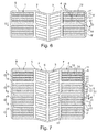
- Figure 6 shows an embodiment in which the profile block rows 4 and 1 are each formed by transverse grooves 8 of separate profile block elements 9 '.
- the profile block elements 9 ' are - analogous to those in Fig.2 shown profile block elements 9 of the tread pattern of Fig.1 - Formally bounded by in each case two sipes 10 and by a transverse groove 8 and a sipe 10 peripheral extender sections 11 '.
- the circumferential extension sections 11 along the optimized sliding direction G seen from the respective circumferential extent portion 11 'upstream delineator 10 or transverse groove 8 starting direction to the subordinate delineator sipe 10 and transverse groove 8 extended fine grooves 12 formed at a distance a from this subordinate delimiting sipe 10 or transverse groove 8 ends.
- the optimized sliding direction G is formed opposite to the designed for the pneumatic vehicle tire for forward rotation direction D.
- Figure 7 shows an alternative embodiment in which the profile block row 4 and the profile block row 1 seen along its extension in the circumferential direction U are each formed of successively arranged in alternating succession profile block elements 9 and 9 '.
- the profile block elements 9 are in their sliding direction G analogous to the profile block elements 9 of FIGS. 1 to 5 for an optimized sliding during braking and the profile block elements 9 'are in their sliding direction G analogous to the profile block elements 9' of Figure 6 designed for optimized driving on ice.
- the optimized sliding direction G of the profile block elements 9 thus also corresponds to the direction of rotation D of the in Figure 7 shown pneumatic vehicle tire when driving forward.
- the optimized sliding direction G of the profile block elements 9 ' is selected counter to the direction of rotation D when moving forward.
- Figure 8 shows a tread block member 9, in which first circumferential extent sections 11, in which the fine grooves 12 are inclined to one axial side, and second circumferential extension portions 11, in which the fine grooves 12 are inclined to the opposite axial side, arranged in the sliding direction G in an alternating sequence one behind the other are.
- FIGS. 9 to 12 show different embodiments of tread block elements 9 ", which are each formed of first circumferential extension sections 11 and second circumferential extension sections 11 'are the circumferential extension sections 11 are - analogous to that in Figure 4 illustrated embodiment - each with its optimized sliding direction G in the direction of rotation D in forward travel and the circumferential extension sections 11 'are each formed with their optimized sliding direction G against the direction of rotation D during forward travel.
- the tread block element 9 is designed with the circumferential extension sections 11 for optimizing the braking on ice and with the peripheral extension sections 11 'for optimizing the drive on ice.
- the circumferential extension sections 11 are each adjacent to one another and the circumferential extension sections 11 'are likewise formed adjacent to each other.
- FIGS. 11 and 12 show exemplary embodiments in which along the circumferential direction U of the tread block element 9 "- in an alternative sequence circumferential extension sections 11 'and 11 are arranged one behind the other.
Landscapes
- Engineering & Computer Science (AREA)
- Mechanical Engineering (AREA)
- Tires In General (AREA)
Abstract
Description
- Die Erfindung betrifft einen Fahrzeugluftreifen mit einem profilierten Laufstreifen mit durch Rillen von einander beabstandeten, radial erhabenen Profilelementen, welche in radialer Richtung nach außen hin durch eine radial äußere, die Bodenkontaktfläche bildende radial äußere Oberfläche begrenzt werden, wobei in der radial äußeren Oberfläche von wenigstens einem Profilelement in Umfangsrichtung U des Fahrzeugluftreifens hintereinander angeordnet Feineinschnitte ausgebildet sind, die sich jeweils in axialer Richtung A des Fahrzeugluftreifens durch das Profilelement hindurch erstrecken und deren größte Richtungskomponente ihrer Erstreckung in axialer Richtung A des Fahrzeugluftreifens ausgerichtet ist, wobei jeweils zwischen zwei in Umfangsrichtung U benachbart hintereinander angeordneten Feineinschnitten ein Umfangserstreckungsabschnitt des Profilelementes ausgebildet ist.
- Derartige Fahrzeugluftreifen sind bekannt.
- Die Reibenergie beim Bremsen auf Eis wird im Wesentlichen durch zwei Mechanismen abgeleitet: Zum einen die Erwärmung des Eises und somit die Wärmeleitung ins Eis und zum anderen das Aufschmelzen des Eises. Die Erwärmung des Eises kann durch das Profil kaum beeinflusst werden. Wesentlicher Faktor zur Erhöhung der Eisreibung ist daher die Erhöhung der Menge des aufgeschmolzenen Eises. Besonders wichtig ist dabei die Abführung des Schmelzwassers von der zwischen radial äußerer Oberfläche von Profilelementen und dem Eis bestehenden Reibfläche.
- Es ist dabei bekannt Laufstreifenprofile mit Profilblockreihen auszubilden, in denen die radial äußere Oberfläche der Profilblockelemente mit vielen in Umfangsrichtung des Reifen hintereinander angeordneten kleinen Feineinschnitten ausgebildet sind, welche sich im Wesentlichen in axialer Richtung des Reifens und somit unter Einschluss eines Winkels von ca. 90° zur Gleitrichtung beim Bremsen bzw. Beschleunigen erstrecken. Es ist bekannt, dass durch diese Ausbildung mit vielen derart senkrecht zur Gleitrichtung ausgerichteten Feineinschnitten die Eisreibung deutlich erhöht werden kann. Allerdings steigt die Höhe des Schmelzwasserfilms unter dem Profilelement zwischen den Feineinschnitten sehr schnell an, so dass die Abfuhr des Schmelzwassers und damit der Griff auf Eis dennoch noch unerwünscht stark beeinträchtigt ist.
- Der Erfindung liegt die Aufgabe zugrunde, bei derartigen Fahrzeugluftreifen die Wasserabfuhr bei Eisreibung und somit den Griff auf Eis weiter zu verbessern.
- Die Aufgabe wird erfindungsgemäß durch die Ausbildung eines Fahrzeugluftreifens mit einem profilierten Laufstreifen mit durch Rillen von einander beabstandeten, radial erhabenen Profilelementen, welche in radialer Richtung nach außen hin durch eine radial äußere, die Bodenkontaktfläche bildende radial äußere Oberfläche begrenzt werden, wobei in der radial äußeren Oberfläche von wenigstens einem Profilelement in Umfangsrichtung U des Fahrzeugluftreifens hintereinander angeordnet Feineinschnitte ausgebildet sind, die sich jeweils in axialer Richtung A des Fahrzeugluftreifens durch das Profilelement hindurch erstrecken und deren größte Richtungskomponente ihrer Erstreckung in axialer Richtung A des Fahrzeugluftreifens ausgerichtet ist, wobei jeweils zwischen zwei in Umfangsrichtung U benachbart hintereinander angeordneten Feineinschnitten ein Umfangserstreckungsabschnitt des Profilelementes ausgebildet ist, gemäß den Merkmalen von Anspruch 1 gelöst, bei dem in der radial äußeren Oberfläche in wenigstens einem Umfangserstreckungsabschnitt des Profilelementes mit einem Abstand d voneinander beabstandet Feinstrillen angeordnet sind, die jeweils mit einer Breite b mit b ≤ 0,3mm und mit einer Tiefe T mit T ≤ 0,5mm ausgebildet sind und die sich jeweils ausgehend von einem der beiden Feineinschnitte unter Einschluss eines Neigungswinkels α mit 40°≤α≤60° zur Umfangsrichtung U ausgelichtet zum anderen Feineinschnitt hin erstrecken und im Abstand a zu diesem anderen Feineinschnitt enden.
- Die Ausbildung ermöglicht es, dass in dem Umfangserstreckungsabschnitt des Profilelementes bei einem Gleiten auf Eis mit Gleitrichtung in Richtung vom zweiten zum ersten Feineinschnitt zusätzliches Schmelzwasser aus dem Umfangserstreckungsabschnitt in den ersten Feineinschnitt geleitet und dann durch diesen Feineinschnitt aus dem Bereich des Profilelements abgeleitet wird. Dabei wird mit Hilfe der Gleitbewegung selbst das Schmelzwasser aus dem Umfangserstreckungsabschnitt und den Feinabschnitten gefördert. Die Ausrichtung der Feinstrillen mit dem Winkel α ermöglicht dabei, dass durch die Ausnutzung der Gleitbewegung selbst das Wasser zielgerichtet schnell in den ersten Feineinschnitt gefördert und eine optimierte Wasserabfuhr umgesetzt werden kann. Die Ausbildung der Feineinschnitte mit ihrer Breite b mit b ≤ 0,3mm und Tiefe T mit T≤0,5mm ermöglicht die Umsetzung einer sicheren Abfuhr des Schmelzwassers aus dem Bereich der Reiboberfläche ohne merkliche Beeinträchtigung der Blocksteifigkeit. Durch die Ausbildung der Feinstrillen mit ihrer Erstreckung ausgehend von dem einen Feineinschnitt bis in einen Abstand a vom zweiten Feineinschnitt, wobei die Feinstrillen im Abstand a vom zweiten Feineinschnitt enden, wird sichergestellt, dass Wasser aus dem zweiten Feineinschnitt beim Gleiten nicht durch die Feinstrillen in die zwischen Umfangserstreckungsabschnitt und Eis gebildete Reibfläche eingeleitet wird. Somit kann auf diese Weise mit einfachen Mitteln unter Nutzung des zwischen radial äußerer Oberfläche im Umfangserstreckungsabschnitt des Profilelementes und der Eisfläche gebildeten hydrodynamischen Druckes und der Gleitbewegung Schmelzwasser verbessert in den ersten Feineinschnitt und somit aus dem Umfangserstreckungsabschnitt abgeleitet werden und hierdurch ein besserer Griff auf Eis umgesetzt werden.
- Besonders vorteilhaft ist die Ausbildung eines Fahrzeugreifens gemäß den Merkmalen von Anspruch 2, wobei die in einem Umfangserstreckungsabschnitt eines Profilelementes ausgebildeten Feinstrillen in der radial äußeren Oberfläche jeweils parallel zueinander erstreckt ausgerichtet sind. Hierdurch wird in einfacher Weise eine besonders gleichmäßige Wasserabfuhr weiter begünstigt.
- Besonders vorteilhaft ist die Ausbildung eines Fahrzeugreifens gemäß den Merkmalen von Anspruch 3, wobei der Abstand a mit 0,5mm ≤ a ≤ 2mm ausgebildet ist. Der Abstand a ist dabei groß genug, um auch bei Verschleiß der in Gleitrichtung vorderen Kante des Umfangserstreckungsabschnitts noch eine ausreichend wirksame Wischlippe sicherzustellen, und dabei klein genug, um eine ausreichende Wirksamkeit der Feinstrillen sicherzustellen.
- Besonders vorteilhaft ist die Ausbildung eines Fahrzeugreifens gemäß den Merkmalen von Anspruch 4, wobei die in Umfangsrichtung U gemessene Erstreckungslänge e der Feinstrillen jeweils mit (0,5 L)≤e ausgebildet ist, wobei L die in der Position der Einmündung der Feinstrille in den einen Feineinschnitt in der radial äußeren Oberfläche in Umfangsrichtung U gemessene Erstreckungslänge des Umfangserstreckungsabschnittes ist. Hierdurch kann in einfacher Weise ein besonders effektiver Wasserabtransport gerade im Bereich großer Schmelzwasserfilmdicke ermöglicht werden.
- Besonders vorteilhaft ist die Ausbildung eines Fahrzeugreifens gemäß den Merkmalen von Anspruch 5, wobei die Breite b mit 0,1mm ≤ b ausgebildet ist. Hierdurch kann in einfacher Weise ein Schließen der Feinstrille verhindert und auch unter Kontaktdruck zwischen Straße und Profilelement ein Wasserdurchfluss wirksam ermöglicht werden.
- Besonders vorteilhaft ist die Ausbildung eines Fahrzeugreifens gemäß den Merkmalen von Anspruch 6, wobei die Tiefe T mit 0,2mm ≤ T ausgebildet ist. hierdurch kann auch nach leichtem Verschleiß die Wirksamkeit noch sichergestellt werden.
- Besonders vorteilhaft ist die Ausbildung eines Fahrzeugreifens gemäß den Merkmalen von Anspruch 7, wobei der Abstand d mit 0,5mm ≤ d ausgebildet ist. Dies ermöglicht in einfacher Weise die Umsetzung einer optimalen Verhältnisses aus großer Kontaktfläche und gutem Schmelzwasserabtransport.
- Besonders vorteilhaft ist die Ausbildung eines Fahrzeugreifens gemäß den Merkmalen von Anspruch 8, wobei das Profilelement ein Profilblockelement - insbesondere einer Profilblockreihe - ist.
- Besonders vorteilhaft ist die Ausbildung eines Fahrzeugreifens gemäß den Merkmalen von Anspruch 9, wobei sich wenigstens die in einem Umfangserstreckungsabschnitt ausgebildeten Feinstrillen jeweils ausgehend von dem einen Feineinschnitt entgegen der Drehrichtung D des Fahrzeugluftreifens bei Vorwärtsfahrt zum anderen Feineinschnitt hin erstrecken und im Abstand a zu diesem anderen Feineinschnitt enden. Die Ausbildung ermöglicht einen optimalen Einsatz in asymetrischen, nicht laufrichtungsgebundenen Profilen und auch eine einfache Optimierung von Traktion und Bremsen.
- Die Erfindung wird im Folgenden an Hand der in den
Figuren 1 bis 12 dargestellten Ausführungsbeispiele näher erläutert. Hierin zeigen - Fig.1
- einen Umfangsabschnitt eines Laufstreifenprofils eines Fahrzeugluftreifens in Draufsicht am Beispiel eines laufrichtungsgebundenen Profils,
- Fig.2
- ein Profilblockelement des Laufstreifenprofils von
Fig.1 in Draufsicht, - Fig.3
- das Profilblockelement von
Fig.2 in Schnittdarstellung gemäß Schnitt III-III vonFig.2 , - Fig.4
- einen Umfangserstreckungsabschnitt des Profilblockelementes von
Fig.2 in Draufsicht, - Fig.5
- Profilblockelement von
Fig.2 in Schnittdarstellung gemäß Schnitt V-V vonFig.4 , - Fig.6
- einen Umfangserstreckungsabschnitt eines Laufstreifenprofils in alternativer Ausbildung in Draufsicht,
- Fig.7
- einen Umfangserstreckungsabschnitt eines Laufstreifenprofils in weiterer alternativer Ausführung in Draufsicht,
- Fig.8
- ein Profilblockelement eines Laufstreifenprofils in Draufsicht analog zur Darstellung von
Fig.2 in alternativer Ausführung, - Fig.9
- ein Profilblockelement in Draufsicht in weiterer alternativer Ausführung,
- Fig.10
- ein Profilblockelement in Draufsicht in weiterer alternativer Ausführung,
- Fig.11
- ein Profilblockelement in Draufsicht in weiterer alternativer Ausführung und
- Fig.12
- ein Profilblockelement in Draufsicht in weiterer alternativer Ausführung.
- Die
Figuren 1 bis 5 zeigen ein Laufstreifenprofil eines Fahrzeugluftreifens mit besonderen Wintereigenschaften, wie beispielsweise eines Winterreifens für Personenkraftwagen (PKW). Das Laufstreifenprofil ist in bekannter Weise mit mehreren in axialer Richtung A des Fahrzeugluftreifens nebeneinander angeordneten Profilblockreihen 1, 2, 3 und 4 ausgebildet, welche jeweils in bekannter Weise durch über den gesamten Umfang des Fahrzeugluftreifens erstreckte und in Umfangsrichtung U des Fahrzeugluftreifens ausgerichtete Umfangsrillen 5, 6 bzw. 7 in axialer Richtung A voneinander getrennt sind. Die Profilblockreihe 1 ist dabei von der Profilblockreihe 2 durch die Umfangsrille 5 getrennt. Die Profilblockreihe 2 und die Profilblockreihe 3 sind durch die Umfangsrille 6 voneinander getrennt. Die Profilblockreihe 3 und die Profilblockreihe 4 sind durch die Umfangsrille 7 voneinander getrennt. Die Profilblockreihen 1 und 4 sind jeweils in einer Reifenschulter ausgebildet und bilden Schulterprofilblockreihen. Die Profilblockreihen 2 und 3 sind zwischen den beiden Schulterprofilblockreihen 1 und 4 ausgebildet. - Die Profilblockreihen 1, 2, 3 und 4 sind jeweils in bekannter Weise aus in Umfangsrichtung U des Fahrzeugluftreifens hintereinander angeordneten und jeweils durch Querrillen 8 voneinander beabstandeten Profilblockelementen 9 bekannter Art ausgebildet. Die Querrillen 8 einer Profilblockreihe 1, 2, 3 bzw. 4 sind jeweils durch die gesamte axiale Erstreckung der jeweiligen Profilblockreihe 1, 2, 3, bzw. 4 hindurch erstreckt ausgebildet. Die Querrillen 8 der Schulterprofilblockreihen 1 und 4 sind jeweils in axialer Richtung A des Fahrzeugluftreifens ausgerichtet. Die Querrillen 8 der Profilblockreihen 2 und 3 sind jeweils unter Einschluss eines Neigungswinkels von maximal 20° zur axialen Richtung A des Fahrzeugluftreifens ausgerichtet und somit als Schrägrillen ausgebildet.
- Die Umfangsrillen 5, 6, 7 sowie die Querrillen 8 sind in radialer Richtung R des Fahrzeugluftreifens nach innen hin jeweils durch einen Rillengrund begrenzt. Die Profilblockelemente 9 der Profilblockreihen 1, 2, 3 und 4 sind in radialer Richtung R des Fahrzeugluftreifens nach außen hin jeweils durch eine, die Straßenkontaktoberfläche bildende radialäußere Oberfläche 13 begrenzt.
- Am Beispiel eines Profilblockelements 9 der Profilblockreihe 4 wird in den
Figuren 2 bis 5 die weitere Ausbildung der Profilblockelemente 9 erläutert. - Wie in den
Figuren 2 und 3 zu erkennen ist, sind in der radialäußeren Oberfläche 13 des Profilblockelementes 9 jeweils mehrere in Umfangsrichtung U des Fahrzeugluftreifens hintereinander angeordnete Feineinschnitte 10 bekannter Art ausgebildet, welche parallel zueinander und zu den das Profilblockelement 9 begrenzenden Querrillen 8 ausgerichtet und durch das gesamte Profilblockelement 9 hindurch erstreckt ausgebildet sind. Die Feineinschnitte 10 des Profilblockelements 9 der Profilblockreihe 4 erstrecken sich somit in axialer Richtung A des Fahrzeugluftreifens. - Durch die Feineinschnitte 10 ist das Profilblockelement 9 in der radial äußeren Oberfläche 13 in mehrere in Umfangsrichtung U des Fahrzeugluftreifens hintereinander angeordnete Umfangserstreckungsabschnitten 11 aufgeteilt. In dem in
Fig.2 dargestellten Profilblockelement 9 sind beispielhaft drei Feineinschnitte 10 in der radial äußeren Oberfläche 13 ausgebildet, die das Profilblockelement in fünf in Umfangsrichtung U des Fahrzeugluftreifens hintereinander angeordnete Umfangserstreckungsabschnitte 11 aufteilen. Wie inFig.2 zu erkennen ist, ist dabei ausgehend von der das Profilblockelement 9 in Umfangsrichtung U - in der Darstellung nach unten hin - begrenzenden Querrille 8 in Umfangsrichtung U - in der Darstellung nach oben hin - gesehen bis zu dem in Umfangsrichtung U ersten Feineinschnitt 10 ein erster Umfangserstreckungsabschnitt 11 gebildet. Längs der Umfangserstreckungsrichtung U - in Darstellung vonFig.2 somit nach oben hin - ist zwischen diesem ersten Feineinschnitt 10 bis zu dem diesem nachfolgend angeordneten zweiten Feineinschnitt 10 ein zweiter Umfangserstreckungsabschnitt 11 gebildet. Nachfolgend ist wiederum zwischen dem zweiten Feineinschnitt 10 und dem in Umfangsrichtung U nachfolgend angeordneten dritten Feineinschnitt 10 ein dritter Umfangserstreckungsabschnitt 11 und anschließend zwischen dem dritten Feineinschnitt 10 und der das Profilblockelement 9 nachfolgend angeordneten, das Profilblockelement 9 begrenzenden Querrille 8 ein vierter Umfangserstreckungsabschnitt 11 gebildet. Somit ist jeweils zwischen zwei in Umfangserstreckungsuchtung U hintereinander angeordneten Feineinschnitten 10 des Profilblockelementes 9 ein Umfangserstreckungsabschnitt 11 gebildet. Ebenso ist jeweils zwischen der das Profilblockelement 9 in Umfangsrichtung U zu einer Seite hin begrenzenden Querrille 8 und dem dieser Querrille 8 in Umfangsrichtung U nächstliegend ausgebildeten Feineinschnitt 10 des Profilblockelementes 9 ein Umfangserstreckungsabschnitt 11 ausgebildet. - Wie in
Fig.1 und 3 dargestellt ist, sind die Querrillen 8 jeweils mit einer Rillenbreite BR und mit einer - ausgehend von der radial äußeren Oberfläche 13 der die Querrille 8 begrenzenden Profilblockelemente 9 in radialer Richtung R nach innen hin gemessenen - Tiefe TR ausgebildet. Die Feineinschnitte 10 sind mit einer in der radial äußeren Oberfläche 13 gemessenen Breite BF und mit einer in radialer Richtung R nach innen hin gemessenen Tiefe TF ausgebildet. Dabei ist BF mit 0,4mm≤BF≤1mm und BQ ist mit 1mm<BQ≤10mm ausgebildet mit BQ>BF. Die Tiefe TQ ist mit 4mm≤TQ≤PT ausgebildet, wobei PT die maximale Profiltiefe ist. PT ist dabei beispielsweise mit 8mm bis 10mm gewählt ausbildet. Die Tiefe TF ist mit 2mm≤TF≤10mm ausgebildet. - In den
Figuren1 bis 4 ist mit einem Pfeil G die Gleitrichtung eingetragen, für welche das Profilblockelement 9 für den Einsatz auf Eis optimiert ausgebildet ist. Wie in denFig.1,2 und 4 zu erkennen ist, ist die Gleitrichtung G in dieser Darstellung diejenige Umfangsrichtung U, die in der Darstellung von unten nach oben hin gerichtet eingetragen ist. Am Beispiel eines zwischen zwei in Umfangsrichtung U hintereinander angeordneten Feineinschnitten 10 ausgebildeten Umfangserstreckungsabschnitts 11, ist die weitere Ausbildung der Umfangserstreckungsabschnitte 11 eines Profilblockelementes 9 inFig.4 näher dargestellt. - Dabei ist zu erkennen, dass im Umfangserstreckungsabschnitt 11 in der radialäußeren Oberfläche 13 eine Vielzahl von parallel zueinander und unter Einschluss eines Neigungswinkels α zur Umfangsrichtung U ausgerichtete Feinstrillen 12 ausgebildet sind, welche sich jeweils ausgehend von dem den Umfangserstreckungsabschnitt 11 in Gleitrichtung G vorgeordnet begrenzenden Feineinschnitt 10 über eine in Umfangsrichtung U gemessene Erstreckungslänge e bis in einen Abstand a von der, den Umfangserstreckungsabschnitt 11 in Gleitrichtung G nachgeordnet begrenzenden Feineinschnitt 10 erstrecken und dort enden.
- Der Neigungswinkel α ist dabei mit 40°≤α≤60° gewählt. Beispielsweise ist α=45° gewählt. Der Abstand a ist mit 0,5mm≤a≤2mm gewählt. Beispielsweise ist a=1mm gewählt. Der Abstand L zwischen den beiden den Umfangserstreckungsabschnitt 11 begrenzenden Feineinschnitten 10 ist - wie in
Figur 4 dargestellt ist - mit L=(a+e) ausgebildet. Die Erstreckungslänge e ist mit (0,5L)≤e gewählt. - Die in einem Umfangserstreckungsabschnitt 11 ausgebildeten parallelen Feinstrillen 12 sind äquidistant zueinander angeordnet. Zwei benachbarte Feinstrillen 12 sind dabei jeweils in einem Abstand d zueinander angeordnet mit 0,5mm≤d≤2mm. Beispielsweise ist d mit d=1mm ausgebildet.
- Die Feinstrillen 12 sind jeweils längst ihrer Erstreckung mit einer konstanten Breite b ausgebildet mit 0,1mm≤b≤0,3mm ausgebildet. Beispielsweise ist b=0,1mm gewählt.
- In dem längs der Erstreckung des Profilblockelementes 9 in Gleitrichtung G ersten Umfangserstreckungsabschnitt 11 des Profilblockelementes 9 erstrecken sich - wie in
Figur 2 zu erkennen ist - die Feinstrillen 12 jeweils ausgehend von der den ersten Umfangserstreckungsabschnitt 11 begrenzenden Querrille 8 ausgehend in Richtung zu der der dieser Querrille 8 in Gleitrichtung G nachfolgend angeordneten ersten Feineinschnitt 10 und enden im Abstand a von diesem Feineinschnitt 10. In dem vierten Umfangserstreckungsabschnitt 11 des Profilblockelementes 9, welcher durch die in Gleitrichtung G das Profilblockelement 9 nachgeordnet begrenzende Querrille 8 begrenzt wird, erstrecken sich die Feinstrillen 12 jeweils ausgehend von dem zu dieser Querrille 8 nächstliegend vorgeordneten und diesen Umfangserstreckungsabschnitt 11 begrenzenden Feineinschnitt 10 in Richtung zu dieser Querrille 8 und enden dort im Abstand a von dieser Querrille 8. - In analoger Weise zu der Ausbildung der Profilblockelemente 9, der Profilblockreihe 4 sind in einem in
Fig. 1 dargestellten Ausführungsbeispiel auch die Profilblockelemente 9 der Profilblockreihen 1, 2 und 3 jeweils mit durch Feineinschnitte 10 begrenzten Umfangserstreckungsabschnitten 11 und mit Feinstrillen 12 ausgebildet. - In anderer Ausführung sind - wie beispielsweise in den
Figuren 6 und 7 dargestellt - die Profilblockreihen 2 und 3 ohne derartige Feinstrillen 12 ausgebildet sind. - In den
Figuren 1 bis 4 ist die Drehrichtung D bei Vorwärtsfahrt des Fahrzeugluftreifens mit für Bremsen auf Eis optimiert ausgebildetem Laufstreifenprofil eingetragen. Dabei ist zu erkennen, dass bei diesem Ausführungsbeispiel die Drehrichtung D bei Vorwärtsfahrt der eingetragenen, für Bremsen auf Eis optimierten Gleitrichtung G entspricht. -
Fig.6 zeigt ein Ausführungsbeispiel, bei welchem die Profilblockreihen 4 und 1 jeweils mit durch Querrillen 8 von einander getrennten Profilblockelementen 9'ausgebildet sind. Die Profilblockelemente 9'sind - analog zu den inFig.2 dargestellten Profilblockelementen 9 des Laufstreifenprofils vonFig.1 - mit durch jeweils zwei Feineinschnitte 10 bzw. durch eine Querrille 8 und einen Feineinschnitt 10 begrenzten Umfangserstreckungsabschnitten 11'ausgebildet. Dabei sind in den Umfangserstreckungsabschnitten 11 jeweils längs der optimierten Gleitrichtung G gesehen von dem den jeweiligen Umfangserstreckungsabschnitt 11' vorgeordnet begrenzenden Feineinschnitt 10 bzw. Querrille 8 ausgehend Richtung zum nachgeordnet begrenzenden Feineinschnitt 10 bzw. Querrille 8 erstreckten Feinstrillen 12 ausgebildet, die im Abstand a von diesem nachgeordnet begrenzenden Feineinschnitt 10 bzw. Querrille 8 enden. In dem inFigur 6 dargestellten Ausführungsbeispiel ist die optimierte Gleitrichtung G entgegen der für den Fahrzeugluftreifen für Vorwärtsfahrt ausgelegten Drehrichtung D ausgebildet. Die Profilblockelemente 9' sind hierdurch für ein optimiertes Antreiben auf Eis ausgelegt. -
Fig.7 zeigt ein alternatives Ausführungsbeispiel, bei welchem die Profilblockreihe 4 und auch die Profilblockreihe 1 längs ihrer Erstreckung in Umfangsrichtung U gesehen jeweils aus in alternierender Abfolge hintereinander angeordneten Profilblockelemente 9 und 9' ausgebildet sind. Die Profilblockelemente 9 sind in ihrer Gleitrichtung G analog zu den Profilblockelementen 9 derFiguren 1 bis 5 für ein optimiertes Gleiten beim Bremsen und die Profilblockelemente 9' sind in ihrer Gleitrichtung G analog zu den Profilblockelementen 9' derFig.6 für ein optimiertes Antreiben auf Eis angelegt. Die optimierte Gleitrichtung G der Profilblockelemente 9 entspricht somit auch der Drehrichtung D des inFig.7 dargestellten Fahrzeugluftreifens bei Vorwärtsfahrt. Die optimierte Gleitrichtung G der Profilblockelemente 9' ist entgegen der Drehrichtung D bei Vorwärtsfahrt gewählt. -
Fig.8 zeigt ein Profilblockelement 9, bei welchem erste Umfangserstreckungsabschnitte 11, in denen die Feinstrillen 12 zur einen axialen Seite hin geneigt sind, und zweite Umfangserstreckungsabschnitte 11, in denen die Feinstrillen 12 zur entgegengesetzten axialen Seite hin geneigt sind, in Gleitrichtung G in alternierender Abfolge hintereinander angeordnet sind. - Die
Figuren 9 bis 12 zeigen unterschiedliche Ausführungsbeispiele von Profilblockelementen 9", welche jeweils aus ersten Umfangserstreckungsabschnitten 11 und aus zweiten Umfangserstreckungsabschnitten 11' ausgebildet sind. Die Umfangserstreckungsabschnitte 11 sind dabei - analog zu dem inFig.4 dargestellten Ausführungsbeispiel - jeweils mit ihrer optimierten Gleitrichtung G in Drehrichtung D bei Vorwärtsfahrt und die Umfangserstreckungsabschnitte 11' sind jeweils mit ihrer optimierten Gleitrichtung G entgegen der Drehrichtung D bei Vorwärtsfahrt ausgebildet. Auf diese Weise ist das Profilblockelement 9 mit den Umfangserstreckungsabschnitten 11 zur Optimierung des Bremsens auf Eis und mit den Umfangserstreckungsabschnitten 11' zur Optimierung des Antriebes auf Eis ausgelegt. In den Ausführungsbeispielen derFiguren 9 und 10 sind dabei die Umfangserstreckungsabschnitte 11 jeweils benachbart zueinander und die Umfangserstreckungsabschnitte 11' sind ebenfalls jeweils benachbart zueinander ausgebildet. In Analogie zur Darstellung vonFigur 8 ist die Neigungsrichtung des einen Umfangserstreckungsabschnitts 11 entgegen der Neigungsrichtung des anderen Umfangserstreckungsabschnittes 11 und der Neigungsrichtung des einen Umfangserstreckungsabschnittes 11' entgegen der Neigungsrichtung des anderen Umfangserstreckungsabschnitts 11' gewählt. - Dabei ist die Neigungsrichtung der in den zueinander benachbart ausgebildeten Umfangserstreckungsabschnitte 11 und 11' ausgebildeten Feinstrillen gleich gewählt - wie beispielsweise in
Fig.10 dargestellt ist - oder in anderer Ausführung entgegengesetzt zueinander gewählt - wie es beispielsweise inFig.9 dargestellt ist- . - Die
Figuren 11 und 12 zeigen Ausführungsbeispiele bei welchem längs der Umfangsrichtung U des Profilblockelementes 9"- in alternativer Abfolge Umfangserstreckungsabschnitte 11' und 11 hintereinander angeordnet sind. - Die Ausführungsbeispiele der Profilblockreihen 4 und 8 von
Fig.7 mit alternativer Abfolge aus Profilblockelementen 9 und 9', welche jeweils in entgegengesetzter Umfangsrichtung U optimierte Gleitlichtungen G aufweisen, eignet sich - ebenso wie die Ausführungen von Profilblockelementen derFiguren 9 bis 12 , bei welchen die Profilblockelemente 9 "mit für entgegengesetzt optimierte Gleitlichtungen G ausgebildeten Umfangserstreckungsabschnitten 11 und 11' ausgebildet sind, auch für einen optimierten Einsatz bei laufrichtungsungebundenen Laufstreifenprofilen. -
- 1
- Profilblockreihe
- 2
- Profilblockreihe
- 3
- Profilblockreihe
- 4
- Profilblockreihe
- 5
- Umfangsrille
- 6
- Umfangsrille
- 7
- Umfangsrille
- 8
- Querrille
- 9
- Profilblockelement
- 10
- Feineinschnitt
- 11
- Umfangserstreckungsabschnitt
- 12
- Feinsrille
- 13
- Radial äußere Oberfläche
- 14
- Abschnitt
Claims (9)
- Fahrzeugluftreifen mit einem profilierten Laufstreifen mit durch Rillen (5,6,7,8) von einander beabstandeten, radial erhabenen Profilelementen, welche in radialer Richtung nach außen hin durch eine radial äußere, die Bodenkontaktfläche bildende radial äußere Oberfläche (13) begrenzt werden,
wobei in der radial äußeren Oberfläche (13) von wenigstens einem Profilelement (9) in Umfangsrichtung U des Fahrzeugluftreifens hintereinander angeordnet Feineinschnitte (10) ausgebildet sind, die sich jeweils in axialer Richtung A des Fahrzeugluftreifens durch das Profilelement (9) hindurch erstrecken und deren größte Richtungskomponente ihrer Erstreckung in axialer Richtung A des Fahrzeugluftreifens ausgerichtet ist, wobei jeweils zwischen zwei in Umfangsrichtung U benachbart hintereinander angeordneten Feineinschnitten (10) ein Umfangserstreckungsabschnitt (11) des Profilelementes (9) ausgebildet ist, dadurch gekennzeichnet,
dass in der radial äußeren Oberfläche (13) in wenigstens einem Umfangserstreckungsabschnitt (11) des Profilelementes (9) mit einem Abstand d voneinander beabstandet Feinstrillen (12) angeordnet sind, die jeweils mit einer Breite b mit b ≤ 0,3mm und mit einer Tiefe T mit T ≤ 0,5mm ausgebildet sind und die sich jeweils ausgehend von einen der beiden Feineinschnitte (10) unter Einschluss eines Neigungswinkels α mit 40°≤α≤60° zur Umfangsrichtung U ausgerichtet zum anderen Feineinschnitt (10) hin erstrecken und im Abstand a zu diesem anderen Feineinschnitt (10) enden. - Fahrzeugluftreifen gemäß den Merkmalen von Anspruch 1,
wobei die in einem Umfangserstreckungsabschnitt (11) eines Profilelementes (9) ausgebildeten Feinstrillen (12) in der radial äußeren Oberfläche (13) jeweils parallel zueinander erstreckt ausgerichtet sind. - Fahrzeugluftreifen gemäß den Merkmalen von Anspruch 1 oder 2,
wobei der Abstand a mit 0,5mm ≤ a ≤ 2mm ausgebildet ist. - Fahrzeugluftreifen gemäß den Merkmalen von einem oder mehreren der vorangegangenen Ansprüche,
wobei die in Umfangsrichtung U gemessene Erstreckungslänge e der Feinstrillen (12) jeweils mit (0,5 L)≤e ausgebildet ist,
wobei L die in der Position der Einmündung der Feinstrille (12) in den einen Feineinschnitt (10) in der radial äußeren Oberfläche (13) in Umfangsrichtung U gemessene Erstreckungslänge des Umfangserstreckungsabschnittes (11) ist. - Fahrzeugluftreifen gemäß den Merkmalen von einem oder mehreren der vorangegangenen Ansprüche,
wobei die Breite b mit 0,1mm ≤ b ausgebildet ist. - Fahrzeugluftreifen gemäß den Merkmalen von einem oder mehreren der vorangegangenen Ansprüche,
wobei die Tiefe T mit 0,2mm ≤ T ausgebildet ist. - Fahrzeugluftreifen gemäß den Merkmalen von einem oder mehreren der vorangegangenen Ansprüche,
wobei der Abstand d mit 0,5mm ≤ d ausgebildet ist. - Fahrzeugluftreifen gemäß den Merkmalen von einem oder mehreren der vorangegangenen Ansprüche,
wobei das Profilelement (9) ein Profilblockelement - insbesondere einer Profilblockreihe (4) - ist. - Fahrzeugluftreifen gemäß den Merkmalen von einem oder mehreren der vorangegangenen Ansprüche,
wobei sich wenigstens die in einem Umfangserstreckungsabschnitt (11) ausgebildeten Feinstrillen (12) jeweils ausgehend von dem einen Feineinschnitt (10) entgegen der Drehrichtung D des Fahrzeugluftreifens bei Vorwärtsfahrt zum anderen Feineinschnitt (10) hin erstrecken und im Abstand a zu diesem anderen Feineinschnitt (10) enden.
Applications Claiming Priority (1)
| Application Number | Priority Date | Filing Date | Title |
|---|---|---|---|
| DE102015207734.9A DE102015207734A1 (de) | 2015-04-28 | 2015-04-28 | Fahrzeugluftreifen |
Publications (2)
| Publication Number | Publication Date |
|---|---|
| EP3088212A1 true EP3088212A1 (de) | 2016-11-02 |
| EP3088212B1 EP3088212B1 (de) | 2020-03-25 |
Family
ID=55237595
Family Applications (1)
| Application Number | Title | Priority Date | Filing Date |
|---|---|---|---|
| EP16153056.3A Active EP3088212B1 (de) | 2015-04-28 | 2016-01-28 | Fahrzeugluftreifen |
Country Status (2)
| Country | Link |
|---|---|
| EP (1) | EP3088212B1 (de) |
| DE (1) | DE102015207734A1 (de) |
Cited By (5)
| Publication number | Priority date | Publication date | Assignee | Title |
|---|---|---|---|---|
| EP3715148A1 (de) * | 2019-03-28 | 2020-09-30 | Continental Reifen Deutschland GmbH | Fahrzeugluftreifen |
| EP3753753A1 (de) * | 2019-06-17 | 2020-12-23 | Continental Reifen Deutschland GmbH | Fahrzeugluftreifen |
| US20230122026A1 (en) * | 2021-10-18 | 2023-04-20 | Sumitomo Rubber Industries, Ltd. | Tire |
| US12122113B2 (en) | 2021-02-03 | 2024-10-22 | Bridgestone Bandag, Llc | Versatile sipe machine |
| USD1063809S1 (en) | 2023-10-16 | 2025-02-25 | Bridgestone Bandag, Llc | Tire |
Citations (3)
| Publication number | Priority date | Publication date | Assignee | Title |
|---|---|---|---|---|
| EP1529661A1 (de) * | 2003-11-04 | 2005-05-11 | Continental Aktiengesellschaft | Fahrzeugluftreifen |
| JP2006151231A (ja) * | 2004-11-30 | 2006-06-15 | Bridgestone Corp | 空気入りタイヤ |
| WO2015091331A1 (en) * | 2013-12-17 | 2015-06-25 | Compagnie Generale Des Etablissements Michelin | Tread band comprising blocks and fine grooves on the blocks |
Family Cites Families (1)
| Publication number | Priority date | Publication date | Assignee | Title |
|---|---|---|---|---|
| JP6834119B2 (ja) * | 2014-12-03 | 2021-02-24 | 横浜ゴム株式会社 | 空気入りタイヤ |
-
2015
- 2015-04-28 DE DE102015207734.9A patent/DE102015207734A1/de not_active Withdrawn
-
2016
- 2016-01-28 EP EP16153056.3A patent/EP3088212B1/de active Active
Patent Citations (3)
| Publication number | Priority date | Publication date | Assignee | Title |
|---|---|---|---|---|
| EP1529661A1 (de) * | 2003-11-04 | 2005-05-11 | Continental Aktiengesellschaft | Fahrzeugluftreifen |
| JP2006151231A (ja) * | 2004-11-30 | 2006-06-15 | Bridgestone Corp | 空気入りタイヤ |
| WO2015091331A1 (en) * | 2013-12-17 | 2015-06-25 | Compagnie Generale Des Etablissements Michelin | Tread band comprising blocks and fine grooves on the blocks |
Cited By (5)
| Publication number | Priority date | Publication date | Assignee | Title |
|---|---|---|---|---|
| EP3715148A1 (de) * | 2019-03-28 | 2020-09-30 | Continental Reifen Deutschland GmbH | Fahrzeugluftreifen |
| EP3753753A1 (de) * | 2019-06-17 | 2020-12-23 | Continental Reifen Deutschland GmbH | Fahrzeugluftreifen |
| US12122113B2 (en) | 2021-02-03 | 2024-10-22 | Bridgestone Bandag, Llc | Versatile sipe machine |
| US20230122026A1 (en) * | 2021-10-18 | 2023-04-20 | Sumitomo Rubber Industries, Ltd. | Tire |
| USD1063809S1 (en) | 2023-10-16 | 2025-02-25 | Bridgestone Bandag, Llc | Tire |
Also Published As
| Publication number | Publication date |
|---|---|
| DE102015207734A1 (de) | 2016-11-03 |
| EP3088212B1 (de) | 2020-03-25 |
Similar Documents
| Publication | Publication Date | Title |
|---|---|---|
| EP0921020B1 (de) | Laufflächenprofil eines Winterreifens | |
| EP3152067B1 (de) | Fahrzeugluftreifen | |
| EP2509803B1 (de) | Laufstreifenprofil eines fahrzeugluftreifens | |
| EP3088212B1 (de) | Fahrzeugluftreifen | |
| EP2773519B1 (de) | Fahrzeugluftreifen | |
| EP3421264B1 (de) | Fahrzeugluftreifen | |
| EP3500442A1 (de) | Fahrzeugluftreifen | |
| EP3256335B1 (de) | Fahrzeugluftreifen | |
| DE69907856T2 (de) | Ein Reifen für Fahrzeugräder | |
| DE102014212902A1 (de) | Fahrzeugluftreifen | |
| EP3441241B1 (de) | Fahrzeugluftreifen | |
| EP3446892B1 (de) | Fahrzeugluftreifen | |
| EP3100872B1 (de) | Fahrzeugluftreifen | |
| EP3224060B1 (de) | Fahrzeugluftreifen | |
| EP3019349B1 (de) | Laufstreifenprofil eines fahrzeugluftreifens | |
| EP1616721B1 (de) | Fahrzeugluftreifen | |
| DE102011055913A1 (de) | Fahrzeugluftreifen | |
| EP1798067B1 (de) | Laufflächenprofil | |
| EP2501561B1 (de) | Laufstreifenprofil eines fahrzeugreifens | |
| EP2322359A1 (de) | Laufstreifenprofil eines Fahrzeugreifens | |
| EP2914448A1 (de) | Fahrzeugluftreifen | |
| DE102015224713A1 (de) | Fahrzeugluftreifen | |
| DE102006058086B4 (de) | Fahrzeugluftreifen | |
| EP2860049B1 (de) | Fahrzeugluftreifen | |
| EP3366494A1 (de) | Fahrzeugreifen |
Legal Events
| Date | Code | Title | Description |
|---|---|---|---|
| PUAI | Public reference made under article 153(3) epc to a published international application that has entered the european phase |
Free format text: ORIGINAL CODE: 0009012 |
|
| AK | Designated contracting states |
Kind code of ref document: A1 Designated state(s): AL AT BE BG CH CY CZ DE DK EE ES FI FR GB GR HR HU IE IS IT LI LT LU LV MC MK MT NL NO PL PT RO RS SE SI SK SM TR |
|
| AX | Request for extension of the european patent |
Extension state: BA ME |
|
| 17P | Request for examination filed |
Effective date: 20170502 |
|
| RBV | Designated contracting states (corrected) |
Designated state(s): AL AT BE BG CH CY CZ DE DK EE ES FI FR GB GR HR HU IE IS IT LI LT LU LV MC MK MT NL NO PL PT RO RS SE SI SK SM TR |
|
| STAA | Information on the status of an ep patent application or granted ep patent |
Free format text: STATUS: REQUEST FOR EXAMINATION WAS MADE |
|
| STAA | Information on the status of an ep patent application or granted ep patent |
Free format text: STATUS: EXAMINATION IS IN PROGRESS |
|
| 17Q | First examination report despatched |
Effective date: 20190409 |
|
| GRAP | Despatch of communication of intention to grant a patent |
Free format text: ORIGINAL CODE: EPIDOSNIGR1 |
|
| STAA | Information on the status of an ep patent application or granted ep patent |
Free format text: STATUS: GRANT OF PATENT IS INTENDED |
|
| INTG | Intention to grant announced |
Effective date: 20191128 |
|
| GRAS | Grant fee paid |
Free format text: ORIGINAL CODE: EPIDOSNIGR3 |
|
| GRAA | (expected) grant |
Free format text: ORIGINAL CODE: 0009210 |
|
| STAA | Information on the status of an ep patent application or granted ep patent |
Free format text: STATUS: THE PATENT HAS BEEN GRANTED |
|
| AK | Designated contracting states |
Kind code of ref document: B1 Designated state(s): AL AT BE BG CH CY CZ DE DK EE ES FI FR GB GR HR HU IE IS IT LI LT LU LV MC MK MT NL NO PL PT RO RS SE SI SK SM TR |
|
| REG | Reference to a national code |
Ref country code: GB Ref legal event code: FG4D Free format text: NOT ENGLISH |
|
| REG | Reference to a national code |
Ref country code: AT Ref legal event code: REF Ref document number: 1248159 Country of ref document: AT Kind code of ref document: T Effective date: 20200415 Ref country code: IE Ref legal event code: FG4D Free format text: LANGUAGE OF EP DOCUMENT: GERMAN |
|
| REG | Reference to a national code |
Ref country code: DE Ref legal event code: R096 Ref document number: 502016009230 Country of ref document: DE |
|
| REG | Reference to a national code |
Ref country code: SE Ref legal event code: TRGR |
|
| PG25 | Lapsed in a contracting state [announced via postgrant information from national office to epo] |
Ref country code: RS Free format text: LAPSE BECAUSE OF FAILURE TO SUBMIT A TRANSLATION OF THE DESCRIPTION OR TO PAY THE FEE WITHIN THE PRESCRIBED TIME-LIMIT Effective date: 20200325 Ref country code: NO Free format text: LAPSE BECAUSE OF FAILURE TO SUBMIT A TRANSLATION OF THE DESCRIPTION OR TO PAY THE FEE WITHIN THE PRESCRIBED TIME-LIMIT Effective date: 20200625 Ref country code: FI Free format text: LAPSE BECAUSE OF FAILURE TO SUBMIT A TRANSLATION OF THE DESCRIPTION OR TO PAY THE FEE WITHIN THE PRESCRIBED TIME-LIMIT Effective date: 20200325 |
|
| PG25 | Lapsed in a contracting state [announced via postgrant information from national office to epo] |
Ref country code: LV Free format text: LAPSE BECAUSE OF FAILURE TO SUBMIT A TRANSLATION OF THE DESCRIPTION OR TO PAY THE FEE WITHIN THE PRESCRIBED TIME-LIMIT Effective date: 20200325 Ref country code: HR Free format text: LAPSE BECAUSE OF FAILURE TO SUBMIT A TRANSLATION OF THE DESCRIPTION OR TO PAY THE FEE WITHIN THE PRESCRIBED TIME-LIMIT Effective date: 20200325 Ref country code: BG Free format text: LAPSE BECAUSE OF FAILURE TO SUBMIT A TRANSLATION OF THE DESCRIPTION OR TO PAY THE FEE WITHIN THE PRESCRIBED TIME-LIMIT Effective date: 20200625 Ref country code: GR Free format text: LAPSE BECAUSE OF FAILURE TO SUBMIT A TRANSLATION OF THE DESCRIPTION OR TO PAY THE FEE WITHIN THE PRESCRIBED TIME-LIMIT Effective date: 20200626 |
|
| REG | Reference to a national code |
Ref country code: NL Ref legal event code: MP Effective date: 20200325 |
|
| REG | Reference to a national code |
Ref country code: LT Ref legal event code: MG4D |
|
| PG25 | Lapsed in a contracting state [announced via postgrant information from national office to epo] |
Ref country code: NL Free format text: LAPSE BECAUSE OF FAILURE TO SUBMIT A TRANSLATION OF THE DESCRIPTION OR TO PAY THE FEE WITHIN THE PRESCRIBED TIME-LIMIT Effective date: 20200325 |
|
| PG25 | Lapsed in a contracting state [announced via postgrant information from national office to epo] |
Ref country code: SK Free format text: LAPSE BECAUSE OF FAILURE TO SUBMIT A TRANSLATION OF THE DESCRIPTION OR TO PAY THE FEE WITHIN THE PRESCRIBED TIME-LIMIT Effective date: 20200325 Ref country code: LT Free format text: LAPSE BECAUSE OF FAILURE TO SUBMIT A TRANSLATION OF THE DESCRIPTION OR TO PAY THE FEE WITHIN THE PRESCRIBED TIME-LIMIT Effective date: 20200325 Ref country code: EE Free format text: LAPSE BECAUSE OF FAILURE TO SUBMIT A TRANSLATION OF THE DESCRIPTION OR TO PAY THE FEE WITHIN THE PRESCRIBED TIME-LIMIT Effective date: 20200325 Ref country code: SM Free format text: LAPSE BECAUSE OF FAILURE TO SUBMIT A TRANSLATION OF THE DESCRIPTION OR TO PAY THE FEE WITHIN THE PRESCRIBED TIME-LIMIT Effective date: 20200325 Ref country code: RO Free format text: LAPSE BECAUSE OF FAILURE TO SUBMIT A TRANSLATION OF THE DESCRIPTION OR TO PAY THE FEE WITHIN THE PRESCRIBED TIME-LIMIT Effective date: 20200325 Ref country code: PT Free format text: LAPSE BECAUSE OF FAILURE TO SUBMIT A TRANSLATION OF THE DESCRIPTION OR TO PAY THE FEE WITHIN THE PRESCRIBED TIME-LIMIT Effective date: 20200818 Ref country code: IS Free format text: LAPSE BECAUSE OF FAILURE TO SUBMIT A TRANSLATION OF THE DESCRIPTION OR TO PAY THE FEE WITHIN THE PRESCRIBED TIME-LIMIT Effective date: 20200725 Ref country code: CZ Free format text: LAPSE BECAUSE OF FAILURE TO SUBMIT A TRANSLATION OF THE DESCRIPTION OR TO PAY THE FEE WITHIN THE PRESCRIBED TIME-LIMIT Effective date: 20200325 |
|
| RAP2 | Party data changed (patent owner data changed or rights of a patent transferred) |
Owner name: CONTINENTAL REIFEN DEUTSCHLAND GMBH |
|
| REG | Reference to a national code |
Ref country code: DE Ref legal event code: R097 Ref document number: 502016009230 Country of ref document: DE |
|
| PG25 | Lapsed in a contracting state [announced via postgrant information from national office to epo] |
Ref country code: DK Free format text: LAPSE BECAUSE OF FAILURE TO SUBMIT A TRANSLATION OF THE DESCRIPTION OR TO PAY THE FEE WITHIN THE PRESCRIBED TIME-LIMIT Effective date: 20200325 Ref country code: IT Free format text: LAPSE BECAUSE OF FAILURE TO SUBMIT A TRANSLATION OF THE DESCRIPTION OR TO PAY THE FEE WITHIN THE PRESCRIBED TIME-LIMIT Effective date: 20200325 Ref country code: ES Free format text: LAPSE BECAUSE OF FAILURE TO SUBMIT A TRANSLATION OF THE DESCRIPTION OR TO PAY THE FEE WITHIN THE PRESCRIBED TIME-LIMIT Effective date: 20200325 |
|
| PLBE | No opposition filed within time limit |
Free format text: ORIGINAL CODE: 0009261 |
|
| STAA | Information on the status of an ep patent application or granted ep patent |
Free format text: STATUS: NO OPPOSITION FILED WITHIN TIME LIMIT |
|
| PG25 | Lapsed in a contracting state [announced via postgrant information from national office to epo] |
Ref country code: PL Free format text: LAPSE BECAUSE OF FAILURE TO SUBMIT A TRANSLATION OF THE DESCRIPTION OR TO PAY THE FEE WITHIN THE PRESCRIBED TIME-LIMIT Effective date: 20200325 |
|
| 26N | No opposition filed |
Effective date: 20210112 |
|
| PG25 | Lapsed in a contracting state [announced via postgrant information from national office to epo] |
Ref country code: SI Free format text: LAPSE BECAUSE OF FAILURE TO SUBMIT A TRANSLATION OF THE DESCRIPTION OR TO PAY THE FEE WITHIN THE PRESCRIBED TIME-LIMIT Effective date: 20200325 |
|
| PG25 | Lapsed in a contracting state [announced via postgrant information from national office to epo] |
Ref country code: MC Free format text: LAPSE BECAUSE OF FAILURE TO SUBMIT A TRANSLATION OF THE DESCRIPTION OR TO PAY THE FEE WITHIN THE PRESCRIBED TIME-LIMIT Effective date: 20200325 |
|
| REG | Reference to a national code |
Ref country code: CH Ref legal event code: PL |
|
| GBPC | Gb: european patent ceased through non-payment of renewal fee |
Effective date: 20210128 |
|
| PG25 | Lapsed in a contracting state [announced via postgrant information from national office to epo] |
Ref country code: LU Free format text: LAPSE BECAUSE OF NON-PAYMENT OF DUE FEES Effective date: 20210128 |
|
| REG | Reference to a national code |
Ref country code: BE Ref legal event code: MM Effective date: 20210131 |
|
| PG25 | Lapsed in a contracting state [announced via postgrant information from national office to epo] |
Ref country code: FR Free format text: LAPSE BECAUSE OF NON-PAYMENT OF DUE FEES Effective date: 20210131 |
|
| PG25 | Lapsed in a contracting state [announced via postgrant information from national office to epo] |
Ref country code: CH Free format text: LAPSE BECAUSE OF NON-PAYMENT OF DUE FEES Effective date: 20210131 Ref country code: GB Free format text: LAPSE BECAUSE OF NON-PAYMENT OF DUE FEES Effective date: 20210128 Ref country code: LI Free format text: LAPSE BECAUSE OF NON-PAYMENT OF DUE FEES Effective date: 20210131 |
|
| PG25 | Lapsed in a contracting state [announced via postgrant information from national office to epo] |
Ref country code: IE Free format text: LAPSE BECAUSE OF NON-PAYMENT OF DUE FEES Effective date: 20210128 |
|
| REG | Reference to a national code |
Ref country code: AT Ref legal event code: MM01 Ref document number: 1248159 Country of ref document: AT Kind code of ref document: T Effective date: 20210128 |
|
| PG25 | Lapsed in a contracting state [announced via postgrant information from national office to epo] |
Ref country code: AT Free format text: LAPSE BECAUSE OF NON-PAYMENT OF DUE FEES Effective date: 20210128 |
|
| PG25 | Lapsed in a contracting state [announced via postgrant information from national office to epo] |
Ref country code: BE Free format text: LAPSE BECAUSE OF NON-PAYMENT OF DUE FEES Effective date: 20210131 |
|
| PG25 | Lapsed in a contracting state [announced via postgrant information from national office to epo] |
Ref country code: HU Free format text: LAPSE BECAUSE OF FAILURE TO SUBMIT A TRANSLATION OF THE DESCRIPTION OR TO PAY THE FEE WITHIN THE PRESCRIBED TIME-LIMIT; INVALID AB INITIO Effective date: 20160128 |
|
| PG25 | Lapsed in a contracting state [announced via postgrant information from national office to epo] |
Ref country code: CY Free format text: LAPSE BECAUSE OF FAILURE TO SUBMIT A TRANSLATION OF THE DESCRIPTION OR TO PAY THE FEE WITHIN THE PRESCRIBED TIME-LIMIT Effective date: 20200325 |
|
| REG | Reference to a national code |
Ref country code: DE Ref legal event code: R081 Ref document number: 502016009230 Country of ref document: DE Owner name: CONTINENTAL REIFEN DEUTSCHLAND GMBH, DE Free format text: FORMER OWNER: CONTINENTAL REIFEN DEUTSCHLAND GMBH, 30165 HANNOVER, DE |
|
| PG25 | Lapsed in a contracting state [announced via postgrant information from national office to epo] |
Ref country code: MK Free format text: LAPSE BECAUSE OF FAILURE TO SUBMIT A TRANSLATION OF THE DESCRIPTION OR TO PAY THE FEE WITHIN THE PRESCRIBED TIME-LIMIT Effective date: 20200325 |
|
| PGFP | Annual fee paid to national office [announced via postgrant information from national office to epo] |
Ref country code: SE Payment date: 20240119 Year of fee payment: 9 |
|
| PG25 | Lapsed in a contracting state [announced via postgrant information from national office to epo] |
Ref country code: TR Free format text: LAPSE BECAUSE OF FAILURE TO SUBMIT A TRANSLATION OF THE DESCRIPTION OR TO PAY THE FEE WITHIN THE PRESCRIBED TIME-LIMIT Effective date: 20200325 |
|
| PG25 | Lapsed in a contracting state [announced via postgrant information from national office to epo] |
Ref country code: MT Free format text: LAPSE BECAUSE OF FAILURE TO SUBMIT A TRANSLATION OF THE DESCRIPTION OR TO PAY THE FEE WITHIN THE PRESCRIBED TIME-LIMIT Effective date: 20200325 |
|
| REG | Reference to a national code |
Ref country code: SE Ref legal event code: EUG |
|
| PGFP | Annual fee paid to national office [announced via postgrant information from national office to epo] |
Ref country code: DE Payment date: 20260131 Year of fee payment: 11 |