EP3088125B1 - High-output-light attenuator, measuring device, and three-dimensional modeling device - Google Patents
High-output-light attenuator, measuring device, and three-dimensional modeling device Download PDFInfo
- Publication number
- EP3088125B1 EP3088125B1 EP15762904.9A EP15762904A EP3088125B1 EP 3088125 B1 EP3088125 B1 EP 3088125B1 EP 15762904 A EP15762904 A EP 15762904A EP 3088125 B1 EP3088125 B1 EP 3088125B1
- Authority
- EP
- European Patent Office
- Prior art keywords
- reflector
- laser beam
- reflected light
- output
- optical attenuator
- Prior art date
- Legal status (The legal status is an assumption and is not a legal conclusion. Google has not performed a legal analysis and makes no representation as to the accuracy of the status listed.)
- Active
Links
- 230000003287 optical effect Effects 0.000 claims description 78
- 238000007493 shaping process Methods 0.000 claims description 28
- 238000005259 measurement Methods 0.000 claims description 22
- 230000002238 attenuated effect Effects 0.000 description 14
- 238000010438 heat treatment Methods 0.000 description 14
- 238000012545 processing Methods 0.000 description 14
- 238000003475 lamination Methods 0.000 description 10
- 238000000034 method Methods 0.000 description 8
- 239000002826 coolant Substances 0.000 description 3
- 238000012360 testing method Methods 0.000 description 3
- 238000009434 installation Methods 0.000 description 2
- 238000003754 machining Methods 0.000 description 2
- 238000002834 transmittance Methods 0.000 description 2
- LFQSCWFLJHTTHZ-UHFFFAOYSA-N Ethanol Chemical compound CCO LFQSCWFLJHTTHZ-UHFFFAOYSA-N 0.000 description 1
- 230000005540 biological transmission Effects 0.000 description 1
- 238000004140 cleaning Methods 0.000 description 1
- 230000000295 complement effect Effects 0.000 description 1
- 238000001816 cooling Methods 0.000 description 1
- 230000003247 decreasing effect Effects 0.000 description 1
- 230000000694 effects Effects 0.000 description 1
- 238000005516 engineering process Methods 0.000 description 1
- 230000014509 gene expression Effects 0.000 description 1
- 230000001678 irradiating effect Effects 0.000 description 1
- 239000000463 material Substances 0.000 description 1
- 229910044991 metal oxide Inorganic materials 0.000 description 1
- 150000004706 metal oxides Chemical class 0.000 description 1
- 238000012544 monitoring process Methods 0.000 description 1
- 230000005855 radiation Effects 0.000 description 1
- 239000004065 semiconductor Substances 0.000 description 1
- 239000000126 substance Substances 0.000 description 1
- 239000000758 substrate Substances 0.000 description 1
- 238000011144 upstream manufacturing Methods 0.000 description 1
- XLYOFNOQVPJJNP-UHFFFAOYSA-N water Substances O XLYOFNOQVPJJNP-UHFFFAOYSA-N 0.000 description 1
Images


Classifications
-
- G—PHYSICS
- G02—OPTICS
- G02B—OPTICAL ELEMENTS, SYSTEMS OR APPARATUS
- G02B27/00—Optical systems or apparatus not provided for by any of the groups G02B1/00 - G02B26/00, G02B30/00
- G02B27/10—Beam splitting or combining systems
- G02B27/14—Beam splitting or combining systems operating by reflection only
- G02B27/144—Beam splitting or combining systems operating by reflection only using partially transparent surfaces without spectral selectivity
-
- B—PERFORMING OPERATIONS; TRANSPORTING
- B23—MACHINE TOOLS; METAL-WORKING NOT OTHERWISE PROVIDED FOR
- B23K—SOLDERING OR UNSOLDERING; WELDING; CLADDING OR PLATING BY SOLDERING OR WELDING; CUTTING BY APPLYING HEAT LOCALLY, e.g. FLAME CUTTING; WORKING BY LASER BEAM
- B23K26/00—Working by laser beam, e.g. welding, cutting or boring
- B23K26/02—Positioning or observing the workpiece, e.g. with respect to the point of impact; Aligning, aiming or focusing the laser beam
- B23K26/03—Observing, e.g. monitoring, the workpiece
- B23K26/032—Observing, e.g. monitoring, the workpiece using optical means
-
- B—PERFORMING OPERATIONS; TRANSPORTING
- B23—MACHINE TOOLS; METAL-WORKING NOT OTHERWISE PROVIDED FOR
- B23K—SOLDERING OR UNSOLDERING; WELDING; CLADDING OR PLATING BY SOLDERING OR WELDING; CUTTING BY APPLYING HEAT LOCALLY, e.g. FLAME CUTTING; WORKING BY LASER BEAM
- B23K26/00—Working by laser beam, e.g. welding, cutting or boring
- B23K26/02—Positioning or observing the workpiece, e.g. with respect to the point of impact; Aligning, aiming or focusing the laser beam
- B23K26/04—Automatically aligning, aiming or focusing the laser beam, e.g. using the back-scattered light
- B23K26/042—Automatically aligning the laser beam
-
- B—PERFORMING OPERATIONS; TRANSPORTING
- B23—MACHINE TOOLS; METAL-WORKING NOT OTHERWISE PROVIDED FOR
- B23K—SOLDERING OR UNSOLDERING; WELDING; CLADDING OR PLATING BY SOLDERING OR WELDING; CUTTING BY APPLYING HEAT LOCALLY, e.g. FLAME CUTTING; WORKING BY LASER BEAM
- B23K26/00—Working by laser beam, e.g. welding, cutting or boring
- B23K26/02—Positioning or observing the workpiece, e.g. with respect to the point of impact; Aligning, aiming or focusing the laser beam
- B23K26/04—Automatically aligning, aiming or focusing the laser beam, e.g. using the back-scattered light
- B23K26/046—Automatically focusing the laser beam
-
- B—PERFORMING OPERATIONS; TRANSPORTING
- B23—MACHINE TOOLS; METAL-WORKING NOT OTHERWISE PROVIDED FOR
- B23K—SOLDERING OR UNSOLDERING; WELDING; CLADDING OR PLATING BY SOLDERING OR WELDING; CUTTING BY APPLYING HEAT LOCALLY, e.g. FLAME CUTTING; WORKING BY LASER BEAM
- B23K26/00—Working by laser beam, e.g. welding, cutting or boring
- B23K26/02—Positioning or observing the workpiece, e.g. with respect to the point of impact; Aligning, aiming or focusing the laser beam
- B23K26/06—Shaping the laser beam, e.g. by masks or multi-focusing
- B23K26/064—Shaping the laser beam, e.g. by masks or multi-focusing by means of optical elements, e.g. lenses, mirrors or prisms
- B23K26/0643—Shaping the laser beam, e.g. by masks or multi-focusing by means of optical elements, e.g. lenses, mirrors or prisms comprising mirrors
-
- B—PERFORMING OPERATIONS; TRANSPORTING
- B23—MACHINE TOOLS; METAL-WORKING NOT OTHERWISE PROVIDED FOR
- B23K—SOLDERING OR UNSOLDERING; WELDING; CLADDING OR PLATING BY SOLDERING OR WELDING; CUTTING BY APPLYING HEAT LOCALLY, e.g. FLAME CUTTING; WORKING BY LASER BEAM
- B23K26/00—Working by laser beam, e.g. welding, cutting or boring
- B23K26/36—Removing material
-
- G—PHYSICS
- G02—OPTICS
- G02B—OPTICAL ELEMENTS, SYSTEMS OR APPARATUS
- G02B27/00—Optical systems or apparatus not provided for by any of the groups G02B1/00 - G02B26/00, G02B30/00
- G02B27/10—Beam splitting or combining systems
- G02B27/108—Beam splitting or combining systems for sampling a portion of a beam or combining a small beam in a larger one, e.g. wherein the area ratio or power ratio of the divided beams significantly differs from unity, without spectral selectivity
-
- G—PHYSICS
- G01—MEASURING; TESTING
- G01J—MEASUREMENT OF INTENSITY, VELOCITY, SPECTRAL CONTENT, POLARISATION, PHASE OR PULSE CHARACTERISTICS OF INFRARED, VISIBLE OR ULTRAVIOLET LIGHT; COLORIMETRY; RADIATION PYROMETRY
- G01J1/00—Photometry, e.g. photographic exposure meter
- G01J1/02—Details
- G01J1/04—Optical or mechanical part supplementary adjustable parts
- G01J1/0407—Optical elements not provided otherwise, e.g. manifolds, windows, holograms, gratings
- G01J1/0418—Optical elements not provided otherwise, e.g. manifolds, windows, holograms, gratings using attenuators
-
- G—PHYSICS
- G02—OPTICS
- G02B—OPTICAL ELEMENTS, SYSTEMS OR APPARATUS
- G02B5/00—Optical elements other than lenses
- G02B5/20—Filters
- G02B5/205—Neutral density filters
Definitions
- the present invention relates to a high-output optical attenuator, a measurement device, and a 3D shaping apparatus.
- patent literature 1 discloses a technique of attenuating a laser beam by using a filter.
- Patent literature 1 Japanese Patent No. 4551385
- the present invention enables to provide a technique of solving the above-described problem.
- One aspect of the present invention provides a high-output optical attenuator according to claim 1.
- a beam output can be attenuated without changing the beam position and the beam diameter.
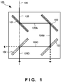
- a high-output optical attenuator 100 according to the first example useful for understanding the present invention will be described with reference to Fig. 1 .
- the high-output optical attenuator 100 is a device that attenuates the output of incident high-output light.
- the high-output optical attenuator 100 includes reflectors 101, 102, 103, and 104.
- the reflector 101 totally reflects incident light 120, and causes reflected light 120A serving as reflected light of the incident light 120 to enter the reflector 102.
- the reflector 102 reflects the reflected light 120A, and causes reflected light 120B serving as reflected light of the reflected light 120A to enter the reflector 103.
- the reflector 103 reflects the reflected light 120B, and causes reflected light 120C serving as reflected light of the reflected light 120B to enter the reflector 104.
- the reflector 104 reflects the reflected light 120C as reflected light 120D having an optical axis 130 which is the same as that of the incident light 120.
- the reflectors 103 and 104 are half mirrors.
- a beam output can be attenuated without changing the beam position and the beam diameter.
- a measurement device using a high-output optical attenuator according to the first embodiment of the present invention will be described with reference to Figs. 2A and 2B .
- the irradiation position (beam position) of a laser beam is confirmed based on a guide beam.
- the output of a laser beam is large, neither the beam position nor beam diameter can be confirmed accurately from the guide beam.
- a test piece To confirm the beam position (focus position) or beam diameter of a laser beam in the laser processing apparatus, a test piece must be set on a work and irradiated with a laser beam at a low output. After that, the test piece must be dismounted from the work in the laser processing apparatus, and a processing trace by the laser beam must be checked through a microscope or the like.
- this operation needs to be executed for both a lamination optical system and a heating optical system.
- a laser beam from the heating optical system obliquely enters a processing material, adjustment of the focus position and beam diameter of the laser beam becomes more difficult.
- a processing laser beam used in a 3D shaping apparatus normally has an output of several hundred W to several kW.
- a light receiving element such as a CCD (Charge Coupled Device) sensor receives weak light having an output in ⁇ W to mW. Therefore, the element such as the CCD sensor cannot detect such a large-output processing laser beam.
- CCD Charge Coupled Device
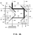
- Figs. 2A and 2B are views for explaining the arrangement of a measurement device 200 using a high-output optical attenuator according to this embodiment.
- the measurement device 200 includes a photodetector 207 and a high-output optical attenuator 208.
- the high-output optical attenuator 208 includes total reflection mirrors 201 and 203, half mirrors 202 and 204, and coolers 250.
- the total reflection mirror 201 is arranged on an optical axis 230 of an incident beam 220, and further arranged on a plane 260 perpendicular to the optical axis 230.
- the total reflection mirror 201 reflects the laser beam 220.
- the laser beam 220 reflected by the total reflection mirror 201 changes its path by 90°, and travels as a laser beam 221 toward the total reflection mirror 203.
- the total reflection mirror 203 is arranged on an axis 240 parallel to the optical axis 230, and further arranged on the same perpendicular plane 260 as the perpendicular plane on which the total reflection mirror 201 is arranged.
- the total reflection mirror 203 reflects the laser beam 221.
- the laser beam 221 reflected by the total reflection mirror 203 changes its path by 90°, and travels as a laser beam 222 toward the half mirror 204.
- the half mirror 204 is arranged on the same axis 240 as the axis on which the total reflection mirror 203 is arranged, and further arranged on a perpendicular plane 270 parallel to the perpendicular plane 260.
- the laser beam 222 is split into a laser beam 224 that is reflected by the half mirror 204, and a laser beam 223 that passes through the half mirror 204.
- the laser beam 222 reflected by the half mirror 204 changes its path by 90°, and travels as the laser beam 224 toward the half mirror 202.
- the laser beam 222 having passed through the half mirror 204 reaches the cooler 250 as the laser beam 223 without changing its path.
- the energies of the laser beam 224 reflected by the half mirror 204 and the laser beam 223 having passed through the half mirror 204 are attenuated in comparison with the laser beam 222 before splitting.
- the half mirror 202 is arranged on the same optical axis 230 as the optical axis on which the total reflection mirror 201 is arranged, and further arranged on the same perpendicular plane 270 as the perpendicular plane on which the half mirror 204 is arranged.
- the laser beam 224 is split into a laser beam 225 that is reflected by the half mirror 202, and a laser beam 226 that passes through the half mirror 202.
- the laser beam 224 reflected by the half mirror 202 changes its path by 90°, and travels as the laser beam 225 toward the photodetector 207.
- the laser beam 224 having passed through the half mirror 202 reaches the cooler 250 as the laser beam 226 without changing its path.
- the energies of the laser beam 225 reflected by the half mirror 202 and the laser beam 226 having passed through the half mirror 202 are attenuated in comparison with the laser beam 224 before splitting.
- the energy of a laser beam is attenuated at the time of reflection (transmission) by the two half mirrors 202 and 204.
- the laser beam 220 entering the high-output optical attenuator 208 comes out of the high-output optical attenuator 208 as the laser beam 225 whose energy is attenuated from that of the laser beam 220.
- the photodetector 207 detects the laser beam 225 coming out of the high-output optical attenuator 208.
- the photodetector 207 is, for example, a CCD sensor or a CMOS (Complementary Metal Oxide Semiconductor) sensor, but is not limited to them as long as this element can detect light.
- CMOS Complementary Metal Oxide Semiconductor
- the user can see the display screen of the photodetector 207 such as a CCD sensor and confirm the beam position of the laser beam 220. Further, the user can know a beam diameter from the beam pattern of the laser beam 220.
- the total reflection mirror 201 is arranged on the optical axis 230 of the laser beam 220, and temporarily diverts the laser beam 220 to a side path. Then, the energy is attenuated using the half mirrors 202 and 204. Hence, the irradiation beam position of the laser beam 220 does not change (shift). The beam position and beam diameter of the laser beam 220 can be detected simultaneously.
- the output needs to be decreased to about six orders of magnitude, and at least two half mirrors are necessary.
- the present invention is not limited to this. The number of half mirrors can be properly increased, as needed.
- the coolers 250 cool the total reflection mirrors 201 and 203. Also, the coolers 250 cool the laser beams 223 and 226 respectively having passed through the half mirrors 202 and 204.
- a coolant 251 circulates through each cooler 250.
- the coolant 251 is, for example, water or alcohol, but is not limited to them as long as the coolant is a substance capable of cooling a laser beam.
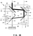
- the arrangement position of the total reflection mirror 203 may be moved down on the axis 240, and the arrangement position of the half mirror 204 may be moved up on the axis 240. Accordingly, the positions of the total reflection mirrors 203 and 201 on the perpendicular plane 260 differ from each other, and the positions of the half mirrors 204 and 202 on the perpendicular plane 270 differ from each other.
- the angle of the total reflection mirror 201 is adjusted so that the reflected beam 221 reaches the total reflection mirror 203.
- the angle of the half mirror 204 is adjusted so that the reflected beam 224 reaches the half mirror 202.
- the arrangement positions of the total reflection mirrors 201 and 203 and half mirrors 202 and 204 are not limited to the arrangements shown in Figs. 2A and 2B , and various arrangements are possible.
- a beam output can be attenuated without changing the beam position and beam diameter of the laser beam. Since a laser beam entering the high-output optical attenuator is temporarily diverted sideways, the output of the laser beam can be attenuated without increasing the thickness of the high-output optical attenuator, and the high-output optical attenuator 208 can be installed in a narrow place.
- the energy of the laser beam 220 can be removed without changing the output of the laser beam 220. Further, since the output of the laser beam 220 can be attenuated without diffusing the laser beam 220, the beam diameter of the laser beam 220 does not change and an accurate beam diameter can be measured.
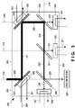
- FIG. 3 is a view for explaining the arrangement of a measurement device 300 using a high-output optical attenuator according to this embodiment.
- the measurement device 300 according to the second embodiment is different from the measurement device according to the first embodiment in that one extra half mirror is arranged.
- the remaining arrangement and operation are the same as those in the first embodiment, so the same reference numerals denote the same arrangement and operation and a detailed description thereof will not be repeated.
- the measurement device 300 includes a high-output optical attenuator 302 and a photodetector 207.
- the high-output optical attenuator 302 includes a half mirror 301 arranged between half mirrors 202 and 204.
- the half mirror 301 is arranged on an axis 310.
- the half mirrors 202, 204, and 301 are arranged on a perpendicular plane 270. Note that the arrangement of the half mirrors 202, 204, and 301 are not limited to this. For example, the arrangement position of the half mirror 301 may a position shifted from the perpendicular plane 270, and various arrangements are possible.
- a laser beam 220 is reflected by a total reflection mirror 220 and travels toward a total reflection mirror 203.
- a laser beam 221 is reflected by the total reflection mirror 203 and travels toward the half mirror 204.
- Part of a laser beam 222 is reflected by the half mirror 204 and travels toward the half mirror 301, and the remaining part passes the half mirror 204 and travels toward a cooler 250.
- Part of a laser beam 224 is reflected by the half mirror 301 and travels as a laser beam 321 toward the cooler 250, and the remaining part passes the half mirror 301 and travels as a laser beam 320 toward the half mirror 202.
- the number of half mirrors is three in the embodiment, the number of half mirrors is not limited to this, and three or more half mirrors may be arranged.
- the number of half mirrors is increased, so the output of a laser beam can be attenuated much more.
- FIG. 4 is a view for explaining the arrangement of a 3D shaping apparatus 400 according to this embodiment.
- the 3D shaping apparatus according to the third embodiment is a 3D shaping apparatus using the high-output optical attenuator described in the first embodiment.
- the remaining arrangement and operation are the same as those in the first embodiment, so the same reference numerals denote the same arrangement and operation and a detailed description thereof will not be repeated.
- the 3D shaping apparatus 400 includes a monitor 401, a cable 402, a lamination optical system housing 403, a heating optical system housing 404, and a support jig 405.
- a photodetector 207 is connected to the monitor 401 via the cable 402. The user can confirm the beam position and beam diameter of a laser beam on a display screen 411 of the monitor 401.
- a high-output optical attenuator 208A is detachably installed in a space for attaching the high-output optical attenuator 208A within the lamination optical system housing 403.
- the high-output optical attenuator 208A is arranged on the optical path of a lamination laser beam 431.
- the output of the lamination laser beam 431 is attenuated by the high-output optical attenuator 208A, and the lamination laser beam 431 reaches the photodetector 207.
- a high-output optical attenuator 208B is arranged outside the heating optical system housing 404. Also, the high-output optical attenuator 208B is arranged on the optical path of a heating laser beam 441, and supported by the support jig 405. The output of the heating laser beam 441 is attenuated by the high-output optical attenuator 208B, and the heating laser beam 441 reaches the photodetector 207.
- the high-output optical attenuators 208A and 208B are used only when the beam positions and beam diameters of the lamination laser beam 431 and heating laser beam 441 need to be measured. When processing a 3D shaped object, the high-output optical attenuators 208A and 208B are detached and not used.
- the high-output optical attenuator 208A is detachable from the 3D shaping apparatus 400, and the high-output optical attenuator 208B can be arranged on the path of a heating laser beam.
- the beam positions and beam diameters of the lamination laser beam 431 and heating laser beam 441 can be measured, for example, before or after processing other than during processing.
- FIG. 5 is a view for explaining the arrangement of a 3D shaping apparatus 500 according to this embodiment.
- the 3D shaping apparatus 500 according to the fourth embodiment is different from the 3D shaping apparatus according to the third embodiment in that a high-output optical attenuator 208B is arranged inside a heating optical system housing 404.
- the remaining arrangement and operation are the same as those in the third embodiment, so the same reference numerals denote the same arrangement and operation and a detailed description thereof will not be repeated.
- the high-output optical attenuator 208B is detachably installed in an installation space ensured inside the heating optical system housing 404.
- a high-output optical attenuator 208A and the high-output optical attenuator 208B are detachable from the 3D shaping apparatus 500.
- the beam positions and beam diameters of a lamination laser beam 431 and heating laser beam 441 can be measured, for example, before or after processing other than during processing.
- FIG. 6 is a view for explaining the arrangement of a 3D shaping apparatus according to this embodiment.
- the 3D shaping apparatus according to the fifth embodiment is different from the 3D shaping apparatus according to the third embodiment in that an integrated measurement device is used.
- the remaining arrangement and operation are the same as those in the first embodiment, so the same reference numerals denote the same arrangement and operation and a detailed description thereof will not be repeated.
- a 3D shaping apparatus 600 uses a measurement device 601 constituted by integrating a high-output optical attenuator 208 and a photodetector 207. Although only a lamination optical system is illustrated in Fig. 6 , the same arrangement also applies to a heating optical system.
- the 3D shaping apparatus 600 has an arrangement in which the measurement device 601 is only placed on a work 602 of the 3D shaping apparatus 600. With the arrangement in which the measurement device 601 is only placed on the work 602, the beam position and beam diameter of a laser beam 431 can be measured easily.
- the measurement device constituted by integrating the high-output optical attenuator and the photodetector is only placed on a work, the beam position and beam diameter of a laser beam can be measured easily. Since the space for attaching the measurement device need not be ensured in the 3D shaping apparatus, the beam position and beam diameter of a laser beam can be easily measured even in an existing 3D shaping apparatus having no installation space.
Landscapes
- Physics & Mathematics (AREA)
- Optics & Photonics (AREA)
- Engineering & Computer Science (AREA)
- Plasma & Fusion (AREA)
- Mechanical Engineering (AREA)
- General Physics & Mathematics (AREA)
- Spectroscopy & Molecular Physics (AREA)
- Length Measuring Devices By Optical Means (AREA)
- Laser Beam Processing (AREA)
Description
- The present invention relates to a high-output optical attenuator, a measurement device, and a 3D shaping apparatus.
- In the above technical field, patent literature 1 discloses a technique of attenuating a laser beam by using a filter.
- Patent literature 1: Japanese Patent No.
4551385 - Prior art which is related to this field of technology can be found e.g. in document
JP 2011 215287 A JP 2011 110560 A JP 2009 099987 A JP H02 140501 U US 2004/0224508 A1 disclosing an apparatus and method for cleaning a substrate using a homogenized and non-polarized radiation beam. Further prior art relating to attenuating arrangements for laser applications is disclosed inJP H07 276069 A JP 2 907319 B2 US 2014/316389 A1 . - In the technique described in this literature, a beam output cannot be attenuated without changing the beam position and the beam diameter.
- The present invention enables to provide a technique of solving the above-described problem.
- One aspect of the present invention provides a high-output optical attenuator according to claim 1.
- Other aspects of the present invention provide a measurement device and a 3D shaping apparatus according to the respective claims.
- According to the present invention, a beam output can be attenuated without changing the beam position and the beam diameter.
-
-
Fig. 1 is a view showing the arrangement of a high-output optical attenuator according to the first example useful for understanding the present invention; -
Fig. 2A is a view showing the arrangement of a measurement device according to the first embodiment of the present invention; -
Fig. 2B is a view showing the arrangement of the measurement device according to the first embodiment of the present invention; -
Fig. 3 is a view showing the arrangement of a measurement device according to the second embodiment of the present invention; -
Fig. 4 is a view showing the arrangement of a 3D shaping apparatus according to the third embodiment of the present invention; -
Fig. 5 is a view showing the arrangement of a 3D shaping apparatus according to the fourth embodiment of the present invention; and -
Fig. 6 is a view showing the arrangement of a 3D shaping apparatus according to the fifth embodiment of the present invention. - Preferred embodiments of the present invention and an example useful for understanding the invention will now be described in detail with reference to the drawings. It should be noted that the relative arrangement of the components, the numerical expressions and numerical values set forth in these embodiments do not limit the scope of the present invention unless it is specifically stated otherwise.
- A high-output
optical attenuator 100 according to the first example useful for understanding the present invention will be described with reference toFig. 1 . The high-outputoptical attenuator 100 is a device that attenuates the output of incident high-output light. - As shown in
Fig. 1 , the high-outputoptical attenuator 100 includesreflectors - The
reflector 101 totally reflectsincident light 120, and causes reflectedlight 120A serving as reflected light of theincident light 120 to enter thereflector 102. Thereflector 102 reflects thereflected light 120A, and causes reflectedlight 120B serving as reflected light of thereflected light 120A to enter thereflector 103. - The
reflector 103 reflects thereflected light 120B, and causes reflectedlight 120C serving as reflected light of thereflected light 120B to enter thereflector 104. Thereflector 104 reflects thereflected light 120C as reflectedlight 120D having anoptical axis 130 which is the same as that of theincident light 120. Thereflectors - According to the first example, a beam output can be attenuated without changing the beam position and the beam diameter.
- A measurement device using a high-output optical attenuator according to the first embodiment of the present invention will be described with reference to
Figs. 2A and2B . - First, a prerequisite technique of this embodiment will be explained. In a laser processing apparatus, the irradiation position (beam position) of a laser beam is confirmed based on a guide beam. When, for example, the output of a laser beam is large, neither the beam position nor beam diameter can be confirmed accurately from the guide beam.
- To confirm the beam position (focus position) or beam diameter of a laser beam in the laser processing apparatus, a test piece must be set on a work and irradiated with a laser beam at a low output. After that, the test piece must be dismounted from the work in the laser processing apparatus, and a processing trace by the laser beam must be checked through a microscope or the like.
- To set the focus position and beam diameter of a laser beam to be predetermined values in this laser processing apparatus, the operation of irradiating a test piece with a laser beam and checking a processing trace generated by the laser beam needs to be performed repetitively.
- In addition, this operation needs to be executed for both a lamination optical system and a heating optical system. When a laser beam from the heating optical system obliquely enters a processing material, adjustment of the focus position and beam diameter of the laser beam becomes more difficult.
- A processing laser beam used in a 3D shaping apparatus normally has an output of several hundred W to several kW. To the contrary, a light receiving element such as a CCD (Charge Coupled Device) sensor receives weak light having an output in µW to mW. Therefore, the element such as the CCD sensor cannot detect such a large-output processing laser beam.
-
Figs. 2A and2B are views for explaining the arrangement of ameasurement device 200 using a high-output optical attenuator according to this embodiment. As shown inFig. 2A , themeasurement device 200 includes aphotodetector 207 and a high-outputoptical attenuator 208. The high-outputoptical attenuator 208 includestotal reflection mirrors half mirrors coolers 250. - The
total reflection mirror 201 is arranged on anoptical axis 230 of anincident beam 220, and further arranged on aplane 260 perpendicular to theoptical axis 230. Thetotal reflection mirror 201 reflects thelaser beam 220. Thelaser beam 220 reflected by thetotal reflection mirror 201 changes its path by 90°, and travels as alaser beam 221 toward thetotal reflection mirror 203. - The
total reflection mirror 203 is arranged on anaxis 240 parallel to theoptical axis 230, and further arranged on the sameperpendicular plane 260 as the perpendicular plane on which thetotal reflection mirror 201 is arranged. Thetotal reflection mirror 203 reflects thelaser beam 221. Thelaser beam 221 reflected by thetotal reflection mirror 203 changes its path by 90°, and travels as alaser beam 222 toward thehalf mirror 204. - The
half mirror 204 is arranged on thesame axis 240 as the axis on which thetotal reflection mirror 203 is arranged, and further arranged on aperpendicular plane 270 parallel to theperpendicular plane 260. Thelaser beam 222 is split into alaser beam 224 that is reflected by thehalf mirror 204, and alaser beam 223 that passes through thehalf mirror 204. - The
laser beam 222 reflected by thehalf mirror 204 changes its path by 90°, and travels as thelaser beam 224 toward thehalf mirror 202. Thelaser beam 222 having passed through thehalf mirror 204 reaches the cooler 250 as thelaser beam 223 without changing its path. - The energies of the
laser beam 224 reflected by thehalf mirror 204 and thelaser beam 223 having passed through thehalf mirror 204 are attenuated in comparison with thelaser beam 222 before splitting. - The
half mirror 202 is arranged on the sameoptical axis 230 as the optical axis on which thetotal reflection mirror 201 is arranged, and further arranged on the sameperpendicular plane 270 as the perpendicular plane on which thehalf mirror 204 is arranged. Thelaser beam 224 is split into alaser beam 225 that is reflected by thehalf mirror 202, and alaser beam 226 that passes through thehalf mirror 202. - The
laser beam 224 reflected by thehalf mirror 202 changes its path by 90°, and travels as thelaser beam 225 toward thephotodetector 207. Thelaser beam 224 having passed through thehalf mirror 202 reaches the cooler 250 as thelaser beam 226 without changing its path. - The energies of the
laser beam 225 reflected by thehalf mirror 202 and thelaser beam 226 having passed through thehalf mirror 202 are attenuated in comparison with thelaser beam 224 before splitting. - In this manner, the energy of a laser beam is attenuated at the time of reflection (transmission) by the two
half mirrors laser beam 220 entering the high-outputoptical attenuator 208 comes out of the high-outputoptical attenuator 208 as thelaser beam 225 whose energy is attenuated from that of thelaser beam 220. - Note that a half mirror in which the transmittance and reflectance of light are equal has been exemplified in the above description, but the present invention is not limited to this. A half mirror in which the transmittance and reflectance of light are different may be used. Also, an example in which two mirrors on the upstream side of incident light are total reflection mirrors, and two mirrors on the downstream side are as half mirrors has been explained above. It is also possible but not claimed that only a mirror arranged at the position of the
total reflection mirror 201 is a total reflection mirror, and mirrors arranged at the remaining positions are half mirrors. - The
photodetector 207 detects thelaser beam 225 coming out of the high-outputoptical attenuator 208. Thephotodetector 207 is, for example, a CCD sensor or a CMOS (Complementary Metal Oxide Semiconductor) sensor, but is not limited to them as long as this element can detect light. - The user can see the display screen of the
photodetector 207 such as a CCD sensor and confirm the beam position of thelaser beam 220. Further, the user can know a beam diameter from the beam pattern of thelaser beam 220. - As described above, the
total reflection mirror 201 is arranged on theoptical axis 230 of thelaser beam 220, and temporarily diverts thelaser beam 220 to a side path. Then, the energy is attenuated using the half mirrors 202 and 204. Hence, the irradiation beam position of thelaser beam 220 does not change (shift). The beam position and beam diameter of thelaser beam 220 can be detected simultaneously. - The outputs of the
laser beams 223 to 226 that have been reflected by or passed through the half mirrors 202 and 204 drop by 0.1% to 1%. However, to detect thelaser beam 220 having an output of 100 W to several kW by thephotodetector 207, the output needs to be decreased to about six orders of magnitude, and at least two half mirrors are necessary. However, the present invention is not limited to this. The number of half mirrors can be properly increased, as needed. - The
coolers 250 cool the total reflection mirrors 201 and 203. Also, thecoolers 250 cool thelaser beams coolant 251 circulates through each cooler 250. Thecoolant 251 is, for example, water or alcohol, but is not limited to them as long as the coolant is a substance capable of cooling a laser beam. - As shown in
Fig. 2B , the arrangement position of thetotal reflection mirror 203 may be moved down on theaxis 240, and the arrangement position of thehalf mirror 204 may be moved up on theaxis 240. Accordingly, the positions of the total reflection mirrors 203 and 201 on theperpendicular plane 260 differ from each other, and the positions of the half mirrors 204 and 202 on theperpendicular plane 270 differ from each other. - In this case, the angle of the
total reflection mirror 201 is adjusted so that the reflectedbeam 221 reaches thetotal reflection mirror 203. In addition, the angle of thehalf mirror 204 is adjusted so that the reflectedbeam 224 reaches thehalf mirror 202. - The arrangement positions of the total reflection mirrors 201 and 203 and half mirrors 202 and 204 are not limited to the arrangements shown in
Figs. 2A and2B , and various arrangements are possible. - According to the first embodiment, a beam output can be attenuated without changing the beam position and beam diameter of the laser beam. Since a laser beam entering the high-output optical attenuator is temporarily diverted sideways, the output of the laser beam can be attenuated without increasing the thickness of the high-output optical attenuator, and the high-output
optical attenuator 208 can be installed in a narrow place. - According to the first embodiment, the energy of the
laser beam 220 can be removed without changing the output of thelaser beam 220. Further, since the output of thelaser beam 220 can be attenuated without diffusing thelaser beam 220, the beam diameter of thelaser beam 220 does not change and an accurate beam diameter can be measured. - A measurement device using a high-output optical attenuator according to the second embodiment of the present invention will be described with reference to
Fig. 3. Fig. 3 is a view for explaining the arrangement of ameasurement device 300 using a high-output optical attenuator according to this embodiment. Themeasurement device 300 according to the second embodiment is different from the measurement device according to the first embodiment in that one extra half mirror is arranged. The remaining arrangement and operation are the same as those in the first embodiment, so the same reference numerals denote the same arrangement and operation and a detailed description thereof will not be repeated. - The
measurement device 300 includes a high-outputoptical attenuator 302 and aphotodetector 207. The high-outputoptical attenuator 302 includes ahalf mirror 301 arranged between half mirrors 202 and 204. Thehalf mirror 301 is arranged on anaxis 310. - The half mirrors 202, 204, and 301 are arranged on a
perpendicular plane 270. Note that the arrangement of the half mirrors 202, 204, and 301 are not limited to this. For example, the arrangement position of thehalf mirror 301 may a position shifted from theperpendicular plane 270, and various arrangements are possible. - A
laser beam 220 is reflected by atotal reflection mirror 220 and travels toward atotal reflection mirror 203. Alaser beam 221 is reflected by thetotal reflection mirror 203 and travels toward thehalf mirror 204. Part of alaser beam 222 is reflected by thehalf mirror 204 and travels toward thehalf mirror 301, and the remaining part passes thehalf mirror 204 and travels toward a cooler 250. - Part of a
laser beam 224 is reflected by thehalf mirror 301 and travels as alaser beam 321 toward the cooler 250, and the remaining part passes thehalf mirror 301 and travels as alaser beam 320 toward thehalf mirror 202. Although the number of half mirrors is three in the embodiment, the number of half mirrors is not limited to this, and three or more half mirrors may be arranged. - According to the second embodiment, the number of half mirrors is increased, so the output of a laser beam can be attenuated much more.
- A 3D shaping apparatus according to the third embodiment of the present invention will be described with reference to
Fig. 4. Fig. 4 is a view for explaining the arrangement of a3D shaping apparatus 400 according to this embodiment. The 3D shaping apparatus according to the third embodiment is a 3D shaping apparatus using the high-output optical attenuator described in the first embodiment. The remaining arrangement and operation are the same as those in the first embodiment, so the same reference numerals denote the same arrangement and operation and a detailed description thereof will not be repeated. - The
3D shaping apparatus 400 includes amonitor 401, acable 402, a laminationoptical system housing 403, a heatingoptical system housing 404, and asupport jig 405. - A
photodetector 207 is connected to themonitor 401 via thecable 402. The user can confirm the beam position and beam diameter of a laser beam on adisplay screen 411 of themonitor 401. - A high-output
optical attenuator 208A is detachably installed in a space for attaching the high-outputoptical attenuator 208A within the laminationoptical system housing 403. The high-outputoptical attenuator 208A is arranged on the optical path of alamination laser beam 431. The output of thelamination laser beam 431 is attenuated by the high-outputoptical attenuator 208A, and thelamination laser beam 431 reaches thephotodetector 207. - A high-output
optical attenuator 208B is arranged outside the heatingoptical system housing 404. Also, the high-outputoptical attenuator 208B is arranged on the optical path of aheating laser beam 441, and supported by thesupport jig 405. The output of theheating laser beam 441 is attenuated by the high-outputoptical attenuator 208B, and theheating laser beam 441 reaches thephotodetector 207. - The high-output
optical attenuators lamination laser beam 431 andheating laser beam 441 need to be measured. When processing a 3D shaped object, the high-outputoptical attenuators - According to the third embodiment, the high-output
optical attenuator 208A is detachable from the3D shaping apparatus 400, and the high-outputoptical attenuator 208B can be arranged on the path of a heating laser beam. Thus, the beam positions and beam diameters of thelamination laser beam 431 andheating laser beam 441 can be measured, for example, before or after processing other than during processing. - A 3D shaping apparatus according to the fourth embodiment of the present invention will be described with reference to
Fig. 5. Fig. 5 is a view for explaining the arrangement of a3D shaping apparatus 500 according to this embodiment. The3D shaping apparatus 500 according to the fourth embodiment is different from the 3D shaping apparatus according to the third embodiment in that a high-outputoptical attenuator 208B is arranged inside a heatingoptical system housing 404. The remaining arrangement and operation are the same as those in the third embodiment, so the same reference numerals denote the same arrangement and operation and a detailed description thereof will not be repeated. - The high-output
optical attenuator 208B is detachably installed in an installation space ensured inside the heatingoptical system housing 404. - According to the fourth embodiment, a high-output
optical attenuator 208A and the high-outputoptical attenuator 208B are detachable from the3D shaping apparatus 500. The beam positions and beam diameters of alamination laser beam 431 andheating laser beam 441 can be measured, for example, before or after processing other than during processing. - A 3D shaping apparatus according to the fifth embodiment of the present invention will be described with reference to
Fig. 6. Fig. 6 is a view for explaining the arrangement of a 3D shaping apparatus according to this embodiment. The 3D shaping apparatus according to the fifth embodiment is different from the 3D shaping apparatus according to the third embodiment in that an integrated measurement device is used. The remaining arrangement and operation are the same as those in the first embodiment, so the same reference numerals denote the same arrangement and operation and a detailed description thereof will not be repeated. - A
3D shaping apparatus 600 uses ameasurement device 601 constituted by integrating a high-outputoptical attenuator 208 and aphotodetector 207. Although only a lamination optical system is illustrated inFig. 6 , the same arrangement also applies to a heating optical system. - The
3D shaping apparatus 600 has an arrangement in which themeasurement device 601 is only placed on awork 602 of the3D shaping apparatus 600. With the arrangement in which themeasurement device 601 is only placed on thework 602, the beam position and beam diameter of alaser beam 431 can be measured easily. - According to the fifth embodiment, since the measurement device constituted by integrating the high-output optical attenuator and the photodetector is only placed on a work, the beam position and beam diameter of a laser beam can be measured easily. Since the space for attaching the measurement device need not be ensured in the 3D shaping apparatus, the beam position and beam diameter of a laser beam can be easily measured even in an existing 3D shaping apparatus having no installation space.
- The present invention has been described above with reference to the embodiments. However, the present invention is not limited to those embodiments. Various changes understandable by those skilled in the art within the scope of the present invention as defined by the claims can be made for the arrangements and details of the present invention. The present invention as defined by the claims also incorporates a system or apparatus that somehow combines different features included in the respective embodiments.
Claims (7)
- A high-output optical attenuator (100, 200) comprising: a first reflector (101, 201), a second reflector (102, 203), a third reflector (103, 204) and a fourth reflector (104, 202), wherein
said first reflector (101, 201) that totally reflects incident light and causes first reflected light serving as reflected light of the incident light to enter said second reflector (102, 203);
said second reflector (102, 203) that reflects the first reflected light and causes second reflected light serving as reflected light of the first reflected light to enter said third reflector (103, 204);
said third reflector (103, 204) that reflects the second reflected light and causes third reflected light serving as reflected light of the second reflected light to enter said fourth reflector (104, 202); and
said fourth reflector (104, 202) that reflects the third reflected light as fourth reflected light having the same optical axis as an optical axis of the incident light,
characterized in that
a pair of said first reflector (101, 201) and said second reflector (102, 203) operates as an optical path changer which changes an optical path from the optical axis of the incident light to an axis parallel to the optical path of the incident light, wherein said first reflector (101, 201) is a total reflection mirror and said second reflector (102, 203) is a total reflection mirror;
at least said third reflector (103, 204) and said fourth reflector (104, 202) operate as an optical attenuator which changes the optical path from the axis parallel to the optical axis to the optical axis of the incident light with attenuating the incident light, wherein said third reflector (103, 204) is a half mirror and said fourth reflector (104, 202) is a half mirror, and
the high-output optical attenuator further comprises a first cooler (250) that cools light passed through said third reflector (103, 204) and is provided detached from said third reflector (103, 204), and a second cooler (250) that cools a light passed through said fourth reflector (104, 202) and is provided detached from said fourth reflector (104, 202). - The high-output optical attenuator according to claim 1,
said first reflector (101, 201) and said fourth reflector (104, 202) are arranged on the optical axis of the incident light, and said second reflector(102, 203) and said third reflector (103, 204) are arranged on an axis parallel to the optical axis. - The high-output optical attenuator according to claim 1 or 2,
said first reflector (101, 201) and said second reflector (102, 203) are arranged on a first perpendicular plane perpendicular to the optical axis, and
said third reflector (103, 204) and said fourth reflector (104, 202) are arranged on a second perpendicular plane parallel to the first perpendicular plane. - The high-output optical attenuator according to any one of claims 1 to 3, further comprising at least one reflector arranged between said third reflector (103, 204) and said fourth reflector(104, 202),
wherein said reflector is a half mirror. - A measurement device comprising a high-output optical attenuator stated in any one of claims 1 to 4, and a photodetector.
- The measurement device according to claim 5, said photodetector is one of a CCD sensor and a CMOS sensor.
- A 3D shaping apparatus for measuring a laser beam for shaping a 3D shaped object using a measurement device stated in any one of claims 5 and 6.
Applications Claiming Priority (1)
| Application Number | Priority Date | Filing Date | Title |
|---|---|---|---|
| PCT/JP2015/056930 WO2016143056A1 (en) | 2015-03-10 | 2015-03-10 | High-output-light attenuator, measuring device, and three-dimensional modeling device |
Publications (3)
| Publication Number | Publication Date |
|---|---|
| EP3088125A1 EP3088125A1 (en) | 2016-11-02 |
| EP3088125A4 EP3088125A4 (en) | 2017-04-26 |
| EP3088125B1 true EP3088125B1 (en) | 2019-11-20 |
Family
ID=56820039
Family Applications (1)
| Application Number | Title | Priority Date | Filing Date |
|---|---|---|---|
| EP15762904.9A Active EP3088125B1 (en) | 2015-03-10 | 2015-03-10 | High-output-light attenuator, measuring device, and three-dimensional modeling device |
Country Status (4)
| Country | Link |
|---|---|
| US (1) | US10162187B2 (en) |
| EP (1) | EP3088125B1 (en) |
| JP (1) | JP5981045B1 (en) |
| WO (1) | WO2016143056A1 (en) |
Families Citing this family (3)
| Publication number | Priority date | Publication date | Assignee | Title |
|---|---|---|---|---|
| JP7296834B2 (en) * | 2019-09-12 | 2023-06-23 | 株式会社ディスコ | Laser processing equipment |
| KR102353291B1 (en) * | 2019-10-22 | 2022-01-21 | 배한성 | Laser beam quality measuring device |
| CN112068297B (en) * | 2020-09-22 | 2025-04-29 | 湖南兵器光电科技有限公司 | Folding fiber laser launch device |
Citations (3)
| Publication number | Priority date | Publication date | Assignee | Title |
|---|---|---|---|---|
| JPH07276069A (en) * | 1994-04-08 | 1995-10-24 | Ishikawajima Harima Heavy Ind Co Ltd | Processing position detector for laser processing machine |
| JP2907319B2 (en) * | 1994-09-20 | 1999-06-21 | 川崎重工業株式会社 | High power laser beam splitter |
| US20140316389A1 (en) * | 2013-03-13 | 2014-10-23 | Optimedica Corporation | Laser eye surgery system |
Family Cites Families (9)
| Publication number | Priority date | Publication date | Assignee | Title |
|---|---|---|---|---|
| US4678298A (en) * | 1982-11-22 | 1987-07-07 | Zoran Perisic | Method and apparatus for three-dimensional photography |
| JPH02140501U (en) | 1989-04-28 | 1990-11-26 | ||
| DE19919092A1 (en) * | 1999-04-27 | 2000-11-02 | Zeiss Carl Jena Gmbh | Arrangement for the optical evaluation of an array of objects |
| JP4062606B2 (en) * | 2003-01-20 | 2008-03-19 | フジノン株式会社 | Low coherence measurement / high coherence measurement common interferometer apparatus and measurement method thereof |
| US20040224508A1 (en) | 2003-05-06 | 2004-11-11 | Applied Materials Israel Ltd | Apparatus and method for cleaning a substrate using a homogenized and non-polarized radiation beam |
| JP4551385B2 (en) | 2006-10-24 | 2010-09-29 | 株式会社半導体エネルギー研究所 | Laser irradiation device |
| NL1036048A1 (en) | 2007-10-15 | 2009-04-16 | Asml Holding Nv | Pulse to pulse energy equalization or light beam intensity. |
| JP2011110560A (en) * | 2009-11-24 | 2011-06-09 | Phoeton Corp | Laser beam machining apparatus and laser beam machining method |
| JP5580638B2 (en) * | 2010-03-31 | 2014-08-27 | 日立造船株式会社 | Optical output attenuator |
-
2015
- 2015-03-10 JP JP2015540768A patent/JP5981045B1/en active Active
- 2015-03-10 WO PCT/JP2015/056930 patent/WO2016143056A1/en not_active Ceased
- 2015-03-10 US US14/763,151 patent/US10162187B2/en not_active Expired - Fee Related
- 2015-03-10 EP EP15762904.9A patent/EP3088125B1/en active Active
Patent Citations (3)
| Publication number | Priority date | Publication date | Assignee | Title |
|---|---|---|---|---|
| JPH07276069A (en) * | 1994-04-08 | 1995-10-24 | Ishikawajima Harima Heavy Ind Co Ltd | Processing position detector for laser processing machine |
| JP2907319B2 (en) * | 1994-09-20 | 1999-06-21 | 川崎重工業株式会社 | High power laser beam splitter |
| US20140316389A1 (en) * | 2013-03-13 | 2014-10-23 | Optimedica Corporation | Laser eye surgery system |
Also Published As
| Publication number | Publication date |
|---|---|
| WO2016143056A1 (en) | 2016-09-15 |
| JP5981045B1 (en) | 2016-08-31 |
| US10162187B2 (en) | 2018-12-25 |
| EP3088125A1 (en) | 2016-11-02 |
| EP3088125A4 (en) | 2017-04-26 |
| US20170038596A1 (en) | 2017-02-09 |
| JPWO2016143056A1 (en) | 2017-04-27 |
Similar Documents
| Publication | Publication Date | Title |
|---|---|---|
| JP6626997B2 (en) | Inspection system | |
| US8427633B1 (en) | Laser beam analysis apparatus | |
| US20140027421A1 (en) | Method of Determining a Focal Point or Beam Profile of a Laser Beam in a Working Field | |
| TWI571180B (en) | Apparatus and method for monitoring a laser beam | |
| US10811145B2 (en) | Plasma diagnosis system using multiple-path Thomson scattering | |
| US11874163B2 (en) | Laser measurement apparatus having a removable and replaceable beam dump | |
| KR20160042068A (en) | Multi-spot illumination for improved detection sensitivity | |
| US10803996B2 (en) | Plasma diagnosis system using multiple-reciprocating-pass Thompson scattering | |
| US10162187B2 (en) | High-output optical attenuator, measurement device, and 3D shaping apparatus | |
| WO2016147752A1 (en) | Optical attenuator | |
| JP6576061B2 (en) | Laser beam intensity distribution measuring apparatus and laser beam intensity distribution measuring method | |
| Grantham et al. | Optical design and initial results from NIST's AMMT/TEMPS facility | |
| Scaggs et al. | Real-time monitoring of thermal lensing of a multikilowatt fiber laser optical system | |
| KR101138453B1 (en) | system provided laserbeam detraction with excellent linear characteristic and monitoring of optical system pollution. | |
| US10616987B2 (en) | System and method for imaging a sample with an illumination source modified by a spatial selective wavelength filter | |
| Guttman | Noninterceptive Beam Profiling of High‐Power Industrial Lasers: New technique uses Rayleigh scatter to fully characterize the laser beam and focus in near real‐time | |
| US9518865B2 (en) | Device for measuring a power density distribution of a radiation source | |
| Harrop et al. | Absorption driven focus shift | |
| CN111795804A (en) | Online testing method and system for high-energy laser reflection optical element | |
| Scaggs et al. | Application-based m-square measurement techniques for industrial lasers | |
| Piehler et al. | Real-time analysis of laser beams by simultaneous imaging on a single camera chip | |
| Guttman et al. | Image of laser from Rayleigh scattering directly correlated to beam waist measurements of high-power lasers | |
| CN117367584A (en) | Self-collimating spectral calibration method for telescope systems | |
| Schwede | Observe the Beam at the Center of Interest: Focus Diagnostics at full Power | |
| Cao et al. | Real-time detection of focal position on surface during laser proceiing by diffractive beam samplers |
Legal Events
| Date | Code | Title | Description |
|---|---|---|---|
| PUAI | Public reference made under article 153(3) epc to a published international application that has entered the european phase |
Free format text: ORIGINAL CODE: 0009012 |
|
| 17P | Request for examination filed |
Effective date: 20150921 |
|
| AK | Designated contracting states |
Kind code of ref document: A1 Designated state(s): AL AT BE BG CH CY CZ DE DK EE ES FI FR GB GR HR HU IE IS IT LI LT LU LV MC MK MT NL NO PL PT RO RS SE SI SK SM TR |
|
| AX | Request for extension of the european patent |
Extension state: BA ME |
|
| A4 | Supplementary search report drawn up and despatched |
Effective date: 20170328 |
|
| RIC1 | Information provided on ipc code assigned before grant |
Ipc: B23K 26/00 20140101ALI20170322BHEP Ipc: B23K 26/21 20140101ALI20170322BHEP Ipc: B29C 67/00 20170101ALI20170322BHEP Ipc: B23K 26/34 20140101AFI20170322BHEP |
|
| RIN1 | Information on inventor provided before grant (corrected) |
Inventor name: FUJITA, YOSHIHITO Inventor name: NIITANI, HARUHIKO Inventor name: GOYA, SANEYUKI Inventor name: DANNO, MINORU Inventor name: WATANABE, TOSHIYA |
|
| STAA | Information on the status of an ep patent application or granted ep patent |
Free format text: STATUS: EXAMINATION IS IN PROGRESS |
|
| 17Q | First examination report despatched |
Effective date: 20171215 |
|
| DAV | Request for validation of the european patent (deleted) | ||
| DAX | Request for extension of the european patent (deleted) | ||
| GRAP | Despatch of communication of intention to grant a patent |
Free format text: ORIGINAL CODE: EPIDOSNIGR1 |
|
| STAA | Information on the status of an ep patent application or granted ep patent |
Free format text: STATUS: GRANT OF PATENT IS INTENDED |
|
| INTG | Intention to grant announced |
Effective date: 20190527 |
|
| GRAS | Grant fee paid |
Free format text: ORIGINAL CODE: EPIDOSNIGR3 |
|
| GRAA | (expected) grant |
Free format text: ORIGINAL CODE: 0009210 |
|
| STAA | Information on the status of an ep patent application or granted ep patent |
Free format text: STATUS: THE PATENT HAS BEEN GRANTED |
|
| RAP1 | Party data changed (applicant data changed or rights of an application transferred) |
Owner name: TECHNOLOGY RESEARCH ASSOCIATION FOR FUTURE ADDITIV |
|
| AK | Designated contracting states |
Kind code of ref document: B1 Designated state(s): AL AT BE BG CH CY CZ DE DK EE ES FI FR GB GR HR HU IE IS IT LI LT LU LV MC MK MT NL NO PL PT RO RS SE SI SK SM TR |
|
| REG | Reference to a national code |
Ref country code: GB Ref legal event code: FG4D |
|
| REG | Reference to a national code |
Ref country code: CH Ref legal event code: EP |
|
| REG | Reference to a national code |
Ref country code: IE Ref legal event code: FG4D |
|
| REG | Reference to a national code |
Ref country code: DE Ref legal event code: R096 Ref document number: 602015042093 Country of ref document: DE |
|
| REG | Reference to a national code |
Ref country code: AT Ref legal event code: REF Ref document number: 1203655 Country of ref document: AT Kind code of ref document: T Effective date: 20191215 |
|
| REG | Reference to a national code |
Ref country code: NL Ref legal event code: MP Effective date: 20191120 |
|
| REG | Reference to a national code |
Ref country code: LT Ref legal event code: MG4D |
|
| PG25 | Lapsed in a contracting state [announced via postgrant information from national office to epo] |
Ref country code: NL Free format text: LAPSE BECAUSE OF FAILURE TO SUBMIT A TRANSLATION OF THE DESCRIPTION OR TO PAY THE FEE WITHIN THE PRESCRIBED TIME-LIMIT Effective date: 20191120 Ref country code: FI Free format text: LAPSE BECAUSE OF FAILURE TO SUBMIT A TRANSLATION OF THE DESCRIPTION OR TO PAY THE FEE WITHIN THE PRESCRIBED TIME-LIMIT Effective date: 20191120 Ref country code: GR Free format text: LAPSE BECAUSE OF FAILURE TO SUBMIT A TRANSLATION OF THE DESCRIPTION OR TO PAY THE FEE WITHIN THE PRESCRIBED TIME-LIMIT Effective date: 20200221 Ref country code: BG Free format text: LAPSE BECAUSE OF FAILURE TO SUBMIT A TRANSLATION OF THE DESCRIPTION OR TO PAY THE FEE WITHIN THE PRESCRIBED TIME-LIMIT Effective date: 20200220 Ref country code: LT Free format text: LAPSE BECAUSE OF FAILURE TO SUBMIT A TRANSLATION OF THE DESCRIPTION OR TO PAY THE FEE WITHIN THE PRESCRIBED TIME-LIMIT Effective date: 20191120 Ref country code: SE Free format text: LAPSE BECAUSE OF FAILURE TO SUBMIT A TRANSLATION OF THE DESCRIPTION OR TO PAY THE FEE WITHIN THE PRESCRIBED TIME-LIMIT Effective date: 20191120 Ref country code: NO Free format text: LAPSE BECAUSE OF FAILURE TO SUBMIT A TRANSLATION OF THE DESCRIPTION OR TO PAY THE FEE WITHIN THE PRESCRIBED TIME-LIMIT Effective date: 20200220 Ref country code: LV Free format text: LAPSE BECAUSE OF FAILURE TO SUBMIT A TRANSLATION OF THE DESCRIPTION OR TO PAY THE FEE WITHIN THE PRESCRIBED TIME-LIMIT Effective date: 20191120 |
|
| PG25 | Lapsed in a contracting state [announced via postgrant information from national office to epo] |
Ref country code: RS Free format text: LAPSE BECAUSE OF FAILURE TO SUBMIT A TRANSLATION OF THE DESCRIPTION OR TO PAY THE FEE WITHIN THE PRESCRIBED TIME-LIMIT Effective date: 20191120 Ref country code: HR Free format text: LAPSE BECAUSE OF FAILURE TO SUBMIT A TRANSLATION OF THE DESCRIPTION OR TO PAY THE FEE WITHIN THE PRESCRIBED TIME-LIMIT Effective date: 20191120 Ref country code: IS Free format text: LAPSE BECAUSE OF FAILURE TO SUBMIT A TRANSLATION OF THE DESCRIPTION OR TO PAY THE FEE WITHIN THE PRESCRIBED TIME-LIMIT Effective date: 20200320 |
|
| PG25 | Lapsed in a contracting state [announced via postgrant information from national office to epo] |
Ref country code: AL Free format text: LAPSE BECAUSE OF FAILURE TO SUBMIT A TRANSLATION OF THE DESCRIPTION OR TO PAY THE FEE WITHIN THE PRESCRIBED TIME-LIMIT Effective date: 20191120 |
|
| PG25 | Lapsed in a contracting state [announced via postgrant information from national office to epo] |
Ref country code: CZ Free format text: LAPSE BECAUSE OF FAILURE TO SUBMIT A TRANSLATION OF THE DESCRIPTION OR TO PAY THE FEE WITHIN THE PRESCRIBED TIME-LIMIT Effective date: 20191120 Ref country code: RO Free format text: LAPSE BECAUSE OF FAILURE TO SUBMIT A TRANSLATION OF THE DESCRIPTION OR TO PAY THE FEE WITHIN THE PRESCRIBED TIME-LIMIT Effective date: 20191120 Ref country code: ES Free format text: LAPSE BECAUSE OF FAILURE TO SUBMIT A TRANSLATION OF THE DESCRIPTION OR TO PAY THE FEE WITHIN THE PRESCRIBED TIME-LIMIT Effective date: 20191120 Ref country code: EE Free format text: LAPSE BECAUSE OF FAILURE TO SUBMIT A TRANSLATION OF THE DESCRIPTION OR TO PAY THE FEE WITHIN THE PRESCRIBED TIME-LIMIT Effective date: 20191120 Ref country code: PT Free format text: LAPSE BECAUSE OF FAILURE TO SUBMIT A TRANSLATION OF THE DESCRIPTION OR TO PAY THE FEE WITHIN THE PRESCRIBED TIME-LIMIT Effective date: 20200412 Ref country code: DK Free format text: LAPSE BECAUSE OF FAILURE TO SUBMIT A TRANSLATION OF THE DESCRIPTION OR TO PAY THE FEE WITHIN THE PRESCRIBED TIME-LIMIT Effective date: 20191120 |
|
| REG | Reference to a national code |
Ref country code: AT Ref legal event code: MK05 Ref document number: 1203655 Country of ref document: AT Kind code of ref document: T Effective date: 20191120 |
|
| REG | Reference to a national code |
Ref country code: DE Ref legal event code: R097 Ref document number: 602015042093 Country of ref document: DE |
|
| PG25 | Lapsed in a contracting state [announced via postgrant information from national office to epo] |
Ref country code: SK Free format text: LAPSE BECAUSE OF FAILURE TO SUBMIT A TRANSLATION OF THE DESCRIPTION OR TO PAY THE FEE WITHIN THE PRESCRIBED TIME-LIMIT Effective date: 20191120 Ref country code: SM Free format text: LAPSE BECAUSE OF FAILURE TO SUBMIT A TRANSLATION OF THE DESCRIPTION OR TO PAY THE FEE WITHIN THE PRESCRIBED TIME-LIMIT Effective date: 20191120 |
|
| PLBE | No opposition filed within time limit |
Free format text: ORIGINAL CODE: 0009261 |
|
| STAA | Information on the status of an ep patent application or granted ep patent |
Free format text: STATUS: NO OPPOSITION FILED WITHIN TIME LIMIT |
|
| REG | Reference to a national code |
Ref country code: DE Ref legal event code: R119 Ref document number: 602015042093 Country of ref document: DE |
|
| 26N | No opposition filed |
Effective date: 20200821 |
|
| PG25 | Lapsed in a contracting state [announced via postgrant information from national office to epo] |
Ref country code: MC Free format text: LAPSE BECAUSE OF FAILURE TO SUBMIT A TRANSLATION OF THE DESCRIPTION OR TO PAY THE FEE WITHIN THE PRESCRIBED TIME-LIMIT Effective date: 20191120 |
|
| REG | Reference to a national code |
Ref country code: CH Ref legal event code: PL |
|
| PG25 | Lapsed in a contracting state [announced via postgrant information from national office to epo] |
Ref country code: SI Free format text: LAPSE BECAUSE OF FAILURE TO SUBMIT A TRANSLATION OF THE DESCRIPTION OR TO PAY THE FEE WITHIN THE PRESCRIBED TIME-LIMIT Effective date: 20191120 Ref country code: PL Free format text: LAPSE BECAUSE OF FAILURE TO SUBMIT A TRANSLATION OF THE DESCRIPTION OR TO PAY THE FEE WITHIN THE PRESCRIBED TIME-LIMIT Effective date: 20191120 Ref country code: AT Free format text: LAPSE BECAUSE OF FAILURE TO SUBMIT A TRANSLATION OF THE DESCRIPTION OR TO PAY THE FEE WITHIN THE PRESCRIBED TIME-LIMIT Effective date: 20191120 |
|
| REG | Reference to a national code |
Ref country code: BE Ref legal event code: MM Effective date: 20200331 |
|
| PG25 | Lapsed in a contracting state [announced via postgrant information from national office to epo] |
Ref country code: LU Free format text: LAPSE BECAUSE OF NON-PAYMENT OF DUE FEES Effective date: 20200310 |
|
| PG25 | Lapsed in a contracting state [announced via postgrant information from national office to epo] |
Ref country code: FR Free format text: LAPSE BECAUSE OF NON-PAYMENT OF DUE FEES Effective date: 20200331 Ref country code: CH Free format text: LAPSE BECAUSE OF NON-PAYMENT OF DUE FEES Effective date: 20200331 Ref country code: DE Free format text: LAPSE BECAUSE OF NON-PAYMENT OF DUE FEES Effective date: 20201001 Ref country code: IE Free format text: LAPSE BECAUSE OF NON-PAYMENT OF DUE FEES Effective date: 20200310 Ref country code: LI Free format text: LAPSE BECAUSE OF NON-PAYMENT OF DUE FEES Effective date: 20200331 Ref country code: IT Free format text: LAPSE BECAUSE OF FAILURE TO SUBMIT A TRANSLATION OF THE DESCRIPTION OR TO PAY THE FEE WITHIN THE PRESCRIBED TIME-LIMIT Effective date: 20191120 |
|
| PG25 | Lapsed in a contracting state [announced via postgrant information from national office to epo] |
Ref country code: BE Free format text: LAPSE BECAUSE OF NON-PAYMENT OF DUE FEES Effective date: 20200331 |
|
| GBPC | Gb: european patent ceased through non-payment of renewal fee |
Effective date: 20200310 |
|
| PG25 | Lapsed in a contracting state [announced via postgrant information from national office to epo] |
Ref country code: GB Free format text: LAPSE BECAUSE OF NON-PAYMENT OF DUE FEES Effective date: 20200310 |
|
| PG25 | Lapsed in a contracting state [announced via postgrant information from national office to epo] |
Ref country code: TR Free format text: LAPSE BECAUSE OF FAILURE TO SUBMIT A TRANSLATION OF THE DESCRIPTION OR TO PAY THE FEE WITHIN THE PRESCRIBED TIME-LIMIT Effective date: 20191120 Ref country code: MT Free format text: LAPSE BECAUSE OF FAILURE TO SUBMIT A TRANSLATION OF THE DESCRIPTION OR TO PAY THE FEE WITHIN THE PRESCRIBED TIME-LIMIT Effective date: 20191120 Ref country code: CY Free format text: LAPSE BECAUSE OF FAILURE TO SUBMIT A TRANSLATION OF THE DESCRIPTION OR TO PAY THE FEE WITHIN THE PRESCRIBED TIME-LIMIT Effective date: 20191120 |
|
| PG25 | Lapsed in a contracting state [announced via postgrant information from national office to epo] |
Ref country code: MK Free format text: LAPSE BECAUSE OF FAILURE TO SUBMIT A TRANSLATION OF THE DESCRIPTION OR TO PAY THE FEE WITHIN THE PRESCRIBED TIME-LIMIT Effective date: 20191120 |