EP3088031B1 - Humidicateur avec un capteur rfid - Google Patents
Humidicateur avec un capteur rfid Download PDFInfo
- Publication number
- EP3088031B1 EP3088031B1 EP16158954.4A EP16158954A EP3088031B1 EP 3088031 B1 EP3088031 B1 EP 3088031B1 EP 16158954 A EP16158954 A EP 16158954A EP 3088031 B1 EP3088031 B1 EP 3088031B1
- Authority
- EP
- European Patent Office
- Prior art keywords
- gases
- rfid tag
- breathing circuit
- patient
- base unit
- Prior art date
- Legal status (The legal status is an assumption and is not a legal conclusion. Google has not performed a legal analysis and makes no representation as to the accuracy of the status listed.)
- Active
Links
- 239000007789 gas Substances 0.000 claims description 293
- 230000029058 respiratory gaseous exchange Effects 0.000 claims description 153
- 230000037361 pathway Effects 0.000 claims description 39
- XLYOFNOQVPJJNP-UHFFFAOYSA-N water Substances O XLYOFNOQVPJJNP-UHFFFAOYSA-N 0.000 claims description 20
- QVGXLLKOCUKJST-UHFFFAOYSA-N atomic oxygen Chemical compound [O] QVGXLLKOCUKJST-UHFFFAOYSA-N 0.000 claims description 18
- 239000001301 oxygen Substances 0.000 claims description 18
- 229910052760 oxygen Inorganic materials 0.000 claims description 18
- 230000000007 visual effect Effects 0.000 claims description 2
- 238000012384 transportation and delivery Methods 0.000 description 15
- 230000007246 mechanism Effects 0.000 description 12
- 239000000523 sample Substances 0.000 description 8
- 239000013078 crystal Substances 0.000 description 7
- 230000000977 initiatory effect Effects 0.000 description 6
- 230000003434 inspiratory effect Effects 0.000 description 6
- 230000000241 respiratory effect Effects 0.000 description 6
- 238000010897 surface acoustic wave method Methods 0.000 description 6
- 230000003247 decreasing effect Effects 0.000 description 4
- 238000010586 diagram Methods 0.000 description 4
- 238000000034 method Methods 0.000 description 4
- 230000001419 dependent effect Effects 0.000 description 3
- 208000001797 obstructive sleep apnea Diseases 0.000 description 3
- 230000004044 response Effects 0.000 description 3
- 230000003444 anaesthetic effect Effects 0.000 description 2
- 230000005540 biological transmission Effects 0.000 description 2
- 230000005494 condensation Effects 0.000 description 2
- 238000009833 condensation Methods 0.000 description 2
- 239000002305 electric material Substances 0.000 description 2
- 238000010438 heat treatment Methods 0.000 description 2
- 239000000463 material Substances 0.000 description 2
- 230000008569 process Effects 0.000 description 2
- 230000008901 benefit Effects 0.000 description 1
- 230000008859 change Effects 0.000 description 1
- 238000004891 communication Methods 0.000 description 1
- 238000011217 control strategy Methods 0.000 description 1
- 230000018044 dehydration Effects 0.000 description 1
- 238000006297 dehydration reaction Methods 0.000 description 1
- 230000009977 dual effect Effects 0.000 description 1
- 238000005516 engineering process Methods 0.000 description 1
- 230000008020 evaporation Effects 0.000 description 1
- 238000001704 evaporation Methods 0.000 description 1
- 230000006870 function Effects 0.000 description 1
- 230000001771 impaired effect Effects 0.000 description 1
- 239000002184 metal Substances 0.000 description 1
- 238000013068 supply chain management Methods 0.000 description 1
- 230000001225 therapeutic effect Effects 0.000 description 1
- 210000003437 trachea Anatomy 0.000 description 1
- 238000002627 tracheal intubation Methods 0.000 description 1
Images


Classifications
-
- A—HUMAN NECESSITIES
- A61—MEDICAL OR VETERINARY SCIENCE; HYGIENE
- A61M—DEVICES FOR INTRODUCING MEDIA INTO, OR ONTO, THE BODY; DEVICES FOR TRANSDUCING BODY MEDIA OR FOR TAKING MEDIA FROM THE BODY; DEVICES FOR PRODUCING OR ENDING SLEEP OR STUPOR
- A61M16/00—Devices for influencing the respiratory system of patients by gas treatment, e.g. mouth-to-mouth respiration; Tracheal tubes
- A61M16/10—Preparation of respiratory gases or vapours
- A61M16/1075—Preparation of respiratory gases or vapours by influencing the temperature
-
- A—HUMAN NECESSITIES
- A61—MEDICAL OR VETERINARY SCIENCE; HYGIENE
- A61M—DEVICES FOR INTRODUCING MEDIA INTO, OR ONTO, THE BODY; DEVICES FOR TRANSDUCING BODY MEDIA OR FOR TAKING MEDIA FROM THE BODY; DEVICES FOR PRODUCING OR ENDING SLEEP OR STUPOR
- A61M16/00—Devices for influencing the respiratory system of patients by gas treatment, e.g. mouth-to-mouth respiration; Tracheal tubes
- A61M16/0057—Pumps therefor
- A61M16/0066—Blowers or centrifugal pumps
- A61M16/0069—Blowers or centrifugal pumps the speed thereof being controlled by respiratory parameters, e.g. by inhalation
-
- A—HUMAN NECESSITIES
- A61—MEDICAL OR VETERINARY SCIENCE; HYGIENE
- A61M—DEVICES FOR INTRODUCING MEDIA INTO, OR ONTO, THE BODY; DEVICES FOR TRANSDUCING BODY MEDIA OR FOR TAKING MEDIA FROM THE BODY; DEVICES FOR PRODUCING OR ENDING SLEEP OR STUPOR
- A61M16/00—Devices for influencing the respiratory system of patients by gas treatment, e.g. mouth-to-mouth respiration; Tracheal tubes
- A61M16/08—Bellows; Connecting tubes ; Water traps; Patient circuits
- A61M16/0875—Connecting tubes
-
- A—HUMAN NECESSITIES
- A61—MEDICAL OR VETERINARY SCIENCE; HYGIENE
- A61M—DEVICES FOR INTRODUCING MEDIA INTO, OR ONTO, THE BODY; DEVICES FOR TRANSDUCING BODY MEDIA OR FOR TAKING MEDIA FROM THE BODY; DEVICES FOR PRODUCING OR ENDING SLEEP OR STUPOR
- A61M16/00—Devices for influencing the respiratory system of patients by gas treatment, e.g. mouth-to-mouth respiration; Tracheal tubes
- A61M16/10—Preparation of respiratory gases or vapours
- A61M16/1075—Preparation of respiratory gases or vapours by influencing the temperature
- A61M16/109—Preparation of respiratory gases or vapours by influencing the temperature the humidifying liquid or the beneficial agent
-
- A—HUMAN NECESSITIES
- A61—MEDICAL OR VETERINARY SCIENCE; HYGIENE
- A61M—DEVICES FOR INTRODUCING MEDIA INTO, OR ONTO, THE BODY; DEVICES FOR TRANSDUCING BODY MEDIA OR FOR TAKING MEDIA FROM THE BODY; DEVICES FOR PRODUCING OR ENDING SLEEP OR STUPOR
- A61M16/00—Devices for influencing the respiratory system of patients by gas treatment, e.g. mouth-to-mouth respiration; Tracheal tubes
- A61M16/10—Preparation of respiratory gases or vapours
- A61M16/1075—Preparation of respiratory gases or vapours by influencing the temperature
- A61M16/1095—Preparation of respiratory gases or vapours by influencing the temperature in the connecting tubes
-
- A—HUMAN NECESSITIES
- A61—MEDICAL OR VETERINARY SCIENCE; HYGIENE
- A61M—DEVICES FOR INTRODUCING MEDIA INTO, OR ONTO, THE BODY; DEVICES FOR TRANSDUCING BODY MEDIA OR FOR TAKING MEDIA FROM THE BODY; DEVICES FOR PRODUCING OR ENDING SLEEP OR STUPOR
- A61M16/00—Devices for influencing the respiratory system of patients by gas treatment, e.g. mouth-to-mouth respiration; Tracheal tubes
- A61M16/10—Preparation of respiratory gases or vapours
- A61M16/14—Preparation of respiratory gases or vapours by mixing different fluids, one of them being in a liquid phase
- A61M16/16—Devices to humidify the respiration air
- A61M16/161—Devices to humidify the respiration air with means for measuring the humidity
-
- A—HUMAN NECESSITIES
- A61—MEDICAL OR VETERINARY SCIENCE; HYGIENE
- A61M—DEVICES FOR INTRODUCING MEDIA INTO, OR ONTO, THE BODY; DEVICES FOR TRANSDUCING BODY MEDIA OR FOR TAKING MEDIA FROM THE BODY; DEVICES FOR PRODUCING OR ENDING SLEEP OR STUPOR
- A61M16/00—Devices for influencing the respiratory system of patients by gas treatment, e.g. mouth-to-mouth respiration; Tracheal tubes
- A61M16/06—Respiratory or anaesthetic masks
- A61M16/0683—Holding devices therefor
-
- A—HUMAN NECESSITIES
- A61—MEDICAL OR VETERINARY SCIENCE; HYGIENE
- A61M—DEVICES FOR INTRODUCING MEDIA INTO, OR ONTO, THE BODY; DEVICES FOR TRANSDUCING BODY MEDIA OR FOR TAKING MEDIA FROM THE BODY; DEVICES FOR PRODUCING OR ENDING SLEEP OR STUPOR
- A61M16/00—Devices for influencing the respiratory system of patients by gas treatment, e.g. mouth-to-mouth respiration; Tracheal tubes
- A61M16/0003—Accessories therefor, e.g. sensors, vibrators, negative pressure
- A61M2016/0027—Accessories therefor, e.g. sensors, vibrators, negative pressure pressure meter
-
- A—HUMAN NECESSITIES
- A61—MEDICAL OR VETERINARY SCIENCE; HYGIENE
- A61M—DEVICES FOR INTRODUCING MEDIA INTO, OR ONTO, THE BODY; DEVICES FOR TRANSDUCING BODY MEDIA OR FOR TAKING MEDIA FROM THE BODY; DEVICES FOR PRODUCING OR ENDING SLEEP OR STUPOR
- A61M16/00—Devices for influencing the respiratory system of patients by gas treatment, e.g. mouth-to-mouth respiration; Tracheal tubes
- A61M16/0003—Accessories therefor, e.g. sensors, vibrators, negative pressure
- A61M2016/003—Accessories therefor, e.g. sensors, vibrators, negative pressure with a flowmeter
- A61M2016/0033—Accessories therefor, e.g. sensors, vibrators, negative pressure with a flowmeter electrical
-
- A—HUMAN NECESSITIES
- A61—MEDICAL OR VETERINARY SCIENCE; HYGIENE
- A61M—DEVICES FOR INTRODUCING MEDIA INTO, OR ONTO, THE BODY; DEVICES FOR TRANSDUCING BODY MEDIA OR FOR TAKING MEDIA FROM THE BODY; DEVICES FOR PRODUCING OR ENDING SLEEP OR STUPOR
- A61M16/00—Devices for influencing the respiratory system of patients by gas treatment, e.g. mouth-to-mouth respiration; Tracheal tubes
- A61M16/10—Preparation of respiratory gases or vapours
- A61M16/1005—Preparation of respiratory gases or vapours with O2 features or with parameter measurement
- A61M2016/102—Measuring a parameter of the content of the delivered gas
- A61M2016/1025—Measuring a parameter of the content of the delivered gas the O2 concentration
-
- A—HUMAN NECESSITIES
- A61—MEDICAL OR VETERINARY SCIENCE; HYGIENE
- A61M—DEVICES FOR INTRODUCING MEDIA INTO, OR ONTO, THE BODY; DEVICES FOR TRANSDUCING BODY MEDIA OR FOR TAKING MEDIA FROM THE BODY; DEVICES FOR PRODUCING OR ENDING SLEEP OR STUPOR
- A61M2205/00—General characteristics of the apparatus
- A61M2205/18—General characteristics of the apparatus with alarm
-
- A—HUMAN NECESSITIES
- A61—MEDICAL OR VETERINARY SCIENCE; HYGIENE
- A61M—DEVICES FOR INTRODUCING MEDIA INTO, OR ONTO, THE BODY; DEVICES FOR TRANSDUCING BODY MEDIA OR FOR TAKING MEDIA FROM THE BODY; DEVICES FOR PRODUCING OR ENDING SLEEP OR STUPOR
- A61M2205/00—General characteristics of the apparatus
- A61M2205/27—General characteristics of the apparatus preventing use
- A61M2205/276—General characteristics of the apparatus preventing use preventing unwanted use
-
- A—HUMAN NECESSITIES
- A61—MEDICAL OR VETERINARY SCIENCE; HYGIENE
- A61M—DEVICES FOR INTRODUCING MEDIA INTO, OR ONTO, THE BODY; DEVICES FOR TRANSDUCING BODY MEDIA OR FOR TAKING MEDIA FROM THE BODY; DEVICES FOR PRODUCING OR ENDING SLEEP OR STUPOR
- A61M2205/00—General characteristics of the apparatus
- A61M2205/33—Controlling, regulating or measuring
- A61M2205/3368—Temperature
-
- A—HUMAN NECESSITIES
- A61—MEDICAL OR VETERINARY SCIENCE; HYGIENE
- A61M—DEVICES FOR INTRODUCING MEDIA INTO, OR ONTO, THE BODY; DEVICES FOR TRANSDUCING BODY MEDIA OR FOR TAKING MEDIA FROM THE BODY; DEVICES FOR PRODUCING OR ENDING SLEEP OR STUPOR
- A61M2205/00—General characteristics of the apparatus
- A61M2205/35—Communication
- A61M2205/3546—Range
- A61M2205/3569—Range sublocal, e.g. between console and disposable
-
- A—HUMAN NECESSITIES
- A61—MEDICAL OR VETERINARY SCIENCE; HYGIENE
- A61M—DEVICES FOR INTRODUCING MEDIA INTO, OR ONTO, THE BODY; DEVICES FOR TRANSDUCING BODY MEDIA OR FOR TAKING MEDIA FROM THE BODY; DEVICES FOR PRODUCING OR ENDING SLEEP OR STUPOR
- A61M2205/00—General characteristics of the apparatus
- A61M2205/35—Communication
- A61M2205/3576—Communication with non implanted data transmission devices, e.g. using external transmitter or receiver
- A61M2205/3592—Communication with non implanted data transmission devices, e.g. using external transmitter or receiver using telemetric means, e.g. radio or optical transmission
-
- A—HUMAN NECESSITIES
- A61—MEDICAL OR VETERINARY SCIENCE; HYGIENE
- A61M—DEVICES FOR INTRODUCING MEDIA INTO, OR ONTO, THE BODY; DEVICES FOR TRANSDUCING BODY MEDIA OR FOR TAKING MEDIA FROM THE BODY; DEVICES FOR PRODUCING OR ENDING SLEEP OR STUPOR
- A61M2205/00—General characteristics of the apparatus
- A61M2205/58—Means for facilitating use, e.g. by people with impaired vision
- A61M2205/581—Means for facilitating use, e.g. by people with impaired vision by audible feedback
-
- A—HUMAN NECESSITIES
- A61—MEDICAL OR VETERINARY SCIENCE; HYGIENE
- A61M—DEVICES FOR INTRODUCING MEDIA INTO, OR ONTO, THE BODY; DEVICES FOR TRANSDUCING BODY MEDIA OR FOR TAKING MEDIA FROM THE BODY; DEVICES FOR PRODUCING OR ENDING SLEEP OR STUPOR
- A61M2205/00—General characteristics of the apparatus
- A61M2205/58—Means for facilitating use, e.g. by people with impaired vision
- A61M2205/583—Means for facilitating use, e.g. by people with impaired vision by visual feedback
-
- A—HUMAN NECESSITIES
- A61—MEDICAL OR VETERINARY SCIENCE; HYGIENE
- A61M—DEVICES FOR INTRODUCING MEDIA INTO, OR ONTO, THE BODY; DEVICES FOR TRANSDUCING BODY MEDIA OR FOR TAKING MEDIA FROM THE BODY; DEVICES FOR PRODUCING OR ENDING SLEEP OR STUPOR
- A61M2205/00—General characteristics of the apparatus
- A61M2205/60—General characteristics of the apparatus with identification means
- A61M2205/6018—General characteristics of the apparatus with identification means providing set-up signals for the apparatus configuration
-
- A—HUMAN NECESSITIES
- A61—MEDICAL OR VETERINARY SCIENCE; HYGIENE
- A61M—DEVICES FOR INTRODUCING MEDIA INTO, OR ONTO, THE BODY; DEVICES FOR TRANSDUCING BODY MEDIA OR FOR TAKING MEDIA FROM THE BODY; DEVICES FOR PRODUCING OR ENDING SLEEP OR STUPOR
- A61M2205/00—General characteristics of the apparatus
- A61M2205/60—General characteristics of the apparatus with identification means
- A61M2205/6054—Magnetic identification systems
-
- A—HUMAN NECESSITIES
- A61—MEDICAL OR VETERINARY SCIENCE; HYGIENE
- A61M—DEVICES FOR INTRODUCING MEDIA INTO, OR ONTO, THE BODY; DEVICES FOR TRANSDUCING BODY MEDIA OR FOR TAKING MEDIA FROM THE BODY; DEVICES FOR PRODUCING OR ENDING SLEEP OR STUPOR
- A61M2210/00—Anatomical parts of the body
- A61M2210/06—Head
- A61M2210/0618—Nose
Definitions
- This invention relates to a sensing system and component identification system, and particularly to a sensing and component identification system for use in a medical environment which allows parameters of therapeutic gases supplied to a patient to be measured.
- a number of products are known in the art for measuring the temperature of gases being supplied to a patient as well as providing feedback to the gas humidification system.
- One common way of controlling humidification systems is to measure the temperature of gas at two points along the conduit used to supply gas to the patient, and using the temperature data gathered to adjust the power output accordingly.
- a first temperature sensor is inserted adjacent to the output of the humidifier chamber and a second temperature sensor is located proximal to the patient (e.g. in or around the patient interface), both measuring temperature data and feeding this back to a central control system which is usually located in the housing of the blower unit or the humidifier unit (it should be noted that it is becoming more common for integrated units to be used - i.e. units where the humidifier chamber is rigidly connected in use to the blower unit).
- the type of sensor currently commonly employed for this purpose is a temperature probe such as a thermistor.
- US Patent No. 5,558,084 to Fisher & Paykel Healthcare Limited describes measuring the temperature proximal to the patient using a temperature probe or transducer inserted into the inspiratory conduit.
- the temperature probe is interfaced to the control system via a cable which extends from the temperature probe along the external surface of the inspiratory conduit to the control system.
- a disadvantage of this type of temperature interface system is the dependency on the correct positioning of the temperature sensors. The correct functioning of the control system is very dependent on these sensors being correctly positioned. Incorrect placement or connection of the temperature sensors can lead to impaired performance of the entire humidification and breathing system.
- a further disadvantage is that gases may be supplied to the patient at a pressure/humidity combination which is inappropriate. It is well known that certain humidity levels are required of gases which are to be administered to a patient.
- Different humidity values are specifically suitable for different delivery interfaces.
- patients or users receiving heated, humidified air through a face mask have different requirements from patients or users who are receiving a gases stream through intubation delivery ('bypassed airway' users).
- 'Intact airway' users who use a nasal cannula have different requirements from users using a mask which covers the nose and mouth.
- Some existing respiratory humidification devices include a control panel located on e.g. the blower unit, which allow users to manually make power adjustments or other adjustments.
- these adjustments often have no direct or intuitive relationship with the actual physical parameters they are intended to control.
- the manual controls indirectly and undesirably adjust the required gases outlet temperature (by adjusting the power to the humidifier chamber heater plate), or the power to a heater wire provided within the conduit connecting the humidifier to patient (by altering the current flowing through the heater wire), or both.
- RFID tags can be used to identify components when interrogated - the use of RFID tags to identify componentry for e.g. supply chain management is known. When used in this manner, RFID tags are pre-programmed with data identifying the item to which the tag is attached along with other details which may include supplier information, destination address or other relevant details.
- US 2007/0144519 describes a system where RFID tags are embedded or attached to various components in a medical breathing circuit in order to identify the individual components.
- the RFID tags may be either a passive or an active device and differently configured tags are attached to the particular individual items which are required to be individually identified.
- Information may be read from the RFID when the tag is polled by interrogation hardware such as a remote transceiver which transmits a radio frequency (RF) wave - i.e. an RF transceiver.
- RF radio frequency
- the RF wave is received by the RFID and modulated.
- the modulated wave contains the tag identification code information and is transmitted back to the interrogation hardware, which receives and decodes the returning tag data and uses the information e.g. to identify and track the position of the particular item to which the tag is attached.
- RFID tags which can gather and transmit real-time data to the unit used to interrogate the RFID tag.
- RFID tags incorporating temperature and pressure sensors are available and are constructed on a material such as a piezo-electric crystal.
- the piezo-electric crystal element is a piece of piezo-electric material cut and finished to a specified geometric shape and orientation with respect to the crystallographic axes of the materials.
- These tags operate by converting an incoming radio wave (i.e. one that is transmitted by interrogation hardware), to a Surface Acoustic Wave (SAW) by using an interdigital converter.
- SAW Surface Acoustic Wave
- the surface acoustic wave reflects from a series of reflection features on the surface of the crystal and creates a pulse train with a period that depends on the temperature or pressure.
- the acoustic wave is then converted back to an RF wave and transmitted from the tag back to the transceiver.
- the receiving station picks up the pulse train and measures the period/frequency of the pulse train to derive e.g. the temperature.
- an RFID tag used to measure temperature is the TELID2-T RFID tag.
- GB2338420 discloses an apparatus and method of treating OSA (Obstructive Sleep Apnea) wherein a Positive Airway Pressure device is utilised to provide a gases supply which is then passed through a humidifier.
- OSA Active Sleep Apnea
- the pressure of gases supplied by the apparatus are controlled so that the required pressure and resulting flow rate is reached at the same time as the required humidity level is reached.
- a control strategy is disclosed where the pressure is incrementally adjusted to keep pace with the increases in humidity.
- a controller 9 which adjusts the speed of fan 21 in response to the humidity level which is estimated on the basis of temperature.
- US2004079370 discloses a flow probe for use in a humidification system is disclosed.
- the flow probe is adapted to be positioned in a humidified gases flow (for example oxygen or anaesthetic gases) such as that which is provided to a patient in a hospital environment.
- the flow probe is designed to provide both temperature and flow rate sensing of the gases flow by incorporating two sensors (preferably thermistors) and the shape and alignment of the probe enables accurate readings by reducing the occurrence of condensation on the sensors.
- the flow sensor is included in humidification control systems which provide a patient with a desired humidity level or simplify the amount of user input required or wherein the flow sensor provides a controller with flow information which may then be used to determine certain, possibly dangerous, conditions (such as incorrect flow sensor placement, breathing circuit disconnected, no water in the humidification chamber or humidity out of required limits).
- US2004074493 discloses a humidifier and humidity sensor is disclosed for use with a breathing assistance apparatus.
- the humidity sensor preferably includes means to sense absolute humidity, relative humidity and/or temperature at both the patient end and humidifier end.
- the humidifier may also include provision to both control independently the humidity and temperature of the gases.
- a chamber manifold is disclosed to facilitate easy connection of the humidifier to various outlets, inlets and sensors.
- a heated conduit is described which provides a more effective temperature profile along its length.
- US 2006/278221 discloses a process and a device/system for the automatic identification of the type of a breathing tube.
- a memory element (5) is connected to the breathing tube (4).
- the memory element carries stored data identifying the breathing tube (4).
- the data are read by a reading unit (6), which is part of a respirator (1). The data may be read when the breathing tube (4) is brought into the vicinity of the respirator (1) or connected thereto.
- the present invention provides a base unit for use as part of a breathing circuit which delivers heated, humidified gases to a patient for medical purposes and a method of using a control system to adjust an output parameter of a breathing circuit which delivers heated, humidified gases to a patient for medical purposes, as claimed.
- the invention is defined in the appended claims. The invention consists in the foregoing and also envisages instructions of which the following gives examples.
- a breathing circuit for the delivery of heated, humidified gases to a patient for medical purposes comprising:
- said RFID tag is configured to act as a gases temperature sensor and is positioned in said patient interface to sense the temperature of gases passing through said patient interface.
- said RFID tag is configured to act as a gases pressure sensor and is positioned in said patient interface to sense the pressure of gases passing through said patient interface.
- said RFID tag is configured to act as a gases flow sensor and is positioned in said patient interface to measure the flow rate of gases passing through said patient interface.
- said RFID tag is positioned in said patient interface and is configured to measure the oxygen content of gases passing through said patient interface.
- said RFID tag is positioned in said patient interface and is configured to measure the humidity of gases passing through said patient interface.
- said output parameters adjusted by said control system include any combination of; fan speed, heater plate power output, breathing conduit heater wire power output.
- said gases transportation pathway is a breathing conduit with an integral heater wire, said heater wire dual-configured to provide heat to the inside surface of said breathing conduit, and also to act as an aerial for said RFID tag.
- said RFID tag is also configured to act as a patient interface identifier.
- said patient interface is one of a nasal cannula, a nasal mask, a full face mask, a tracheostomy fitting.
- control system includes a number of pre-set identification profiles, said RFID interrogator interrogating said RFID tag and identifying which type of said patient interface is connected to said blower unit, said control system automatically adjusting the initial value of said output parameters depending on said identified component.
- At least one RFID tag in each component of said breathing circuit contains data relating to an expiry date for that component, said control system in use interrogating said RFID tag and comparing the present date to said expiry date and initiating an alarm condition if said expiry date has passed.
- said RFID tag is of the semi-passive or active type, and said integral heater wire is configured to provide power to said RFID tag.
- said RFID tag is of the semi-passive or active type, and includes an integral power supply.
- said blower unit also includes user-operable control adapted to allow a user to set output parameters of said breathing circuit.
- Preferably said user-set output parameters are one or both of gases temperature and gases humidity.
- a breathing circuit for the delivery of heated, humidified gases to a patient for medical purposes comprising:
- said RFID tag is configured to act as a gases temperature sensor and is positioned in said patient interface to sense the temperature of gases passing through said patient interface.
- said RFID tag is configured to act as a gases flow sensor and is positioned in said patient interface to measure the flow rate of gases passing through said patient interface.
- said RFID tag is positioned in said patient interface and is configured to measure the oxygen content of gases passing through said patient interface.
- said RFID tag is positioned in said patient interface and is configured to measure the humidity of gases passing through said patient interface.
- said output parameters adjusted by said control system include any combination of; fan speed, heater plate power output, breathing conduit heater wire power output.
- said RFID tag is also configured to act as a patient interface identifier.
- said patient interface is one of a nasal cannula, a nasal mask, a full face mask, a tracheostomy fitting.
- control system includes a number of pre-set identification profiles, said RFID interrogator interrogating said RFID tag and identifying which type of said patient interface is connected to said blower unit, said control system automatically adjusting the initial value of said output parameters depending on said identified component.
- At least one RFID tag in each component of said breathing circuit contains data relating to an expiry date for that component, said control system in use interrogating said RFID tag and comparing the present date to said expiry date and initiating an alarm condition if said expiry date has passed.
- said RFID tag is of the semi-passive or active type, and includes an integral power supply.
- said RFID tag is of the semi-passive or active type, and said integral heater wire is configured to provide power to said RFID tag.
- said blower unit also includes user-operable control adapted to allow a user to set output parameters of said breathing circuit.
- Preferably said user-set output parameters are one or both of gases temperature and gases humidity.
- a base unit for use as part of a breathing circuit which delivers heated, humidified gases to a patient for medical purposes said breathing circuit of the type that includes a humidifier chamber adapted to hold a quantity of water and having an inlet and an outlet to allow gases to flow through said humidifier chamber, a source of pressurised gases which in use are delivered to the inlet of said humidifier chamber, and a gases transportation pathway connected to said outlet of said humidifier chamber to convey said gases flow to said patient, said gases transportation pathway including a patient interface adapted to supply said patient with said gases flow, said base unit including; a heater plate adapted to allow said humidifier chamber to in use be located on said plate, so that said heater plate heats said quantity of water in said humidifier chamber and gases flowing through said chamber become heated and humidified, a control system configured to adjust one or more output parameters of said breathing circuit, said control system including an RFID interrogator adapted to interrogate and receive data from at least one RFID tag in real time, said RFID interrogator receiving data relating to said sensed parameter, said control system adjusting the
- said RFID interrogator is adapted to receive RFID tag data relating to any one of or any combination of: gases temperature, gases pressure, gases flow, gases humidity and gases oxygen content.
- said output parameters adjusted by said control system include any one of or any combination of: fan speed, heater plate power output, breathing conduit heater wire power output.
- said RFID interrogator is adapted to receive RFID tag data relating to the identity of components in said breathing circuit in use.
- control system includes a number of pre-set identification profiles, said RFID interrogator interrogating RFID tags attached to components in said breathing circuit and said control system programmed to identify which type of patient interface is being used in said breathing circuit, said control system automatically adjusting the initial value of said output parameters depending on said identified component.
- control system is further adapted to receive data relating to expiry dates if said data is available when said RFID interrogator interrogates said at least one RFID tag, said control system in use comparing the present date to said expiry date and initiating an alarm condition if said expiry date has passed.
- said base unit also includes a user-operable control adapted to allow a user to set output parameters of said base unit.
- Preferably said user-set output parameters are one or both of gases temperature and gases humidity.
- a gases conduit for use as part of a breathing circuit which delivers heated, humidified gases to a patient for medical purposes said breathing conduit having a first end adapted for connection to the outlet of a humidifier chamber, and a second, patient end, said gases conduit including an RFID tag located at or close to said patient end, said RFID tag adapted to sense a parameter of said gases passing through said gases transportation pathway.
- said RFID tag is configured to act as a gases temperature sensor and is positioned at or close to said patient end to sense the temperature of gases passing through said patient interface.
- said RFID tag is configured to act as a gases pressure sensor and is positioned at or close to said patient end to sense the pressure of gases passing through said patient interface.
- said RFID tag is configured to act as a gases flow sensor and is positioned at or close to said patient end to sense the flow rate of gases passing through said patient interface.
- said RFID tag is configured to act as a gases oxygen content sensor and is positioned at or close to said patient end to sense the oxygen content of gases passing through said patient interface.
- said RFID tag is configured to act as a gases humidity sensor and is positioned at or close to said patient end to sense the humidity of gases passing through said patient interface.
- said gases conduit is a breathing conduit with an integral heater wire, said heater wire dual-configured to provide heat to the inside surface of said breathing conduit, and also to act as an aerial for said RFID tag.
- said RFID tag is also configured to act as a component identifier.
- said RFID tag contains data relating to an expiry date for the gases conduit.
- said RFID tag is of the semi-passive or active type, and said integral heater wire is configured to provide power to said RFID tag.
- said RFID tag is of the semi-passive or active type, and includes an integral power supply.
- a patient interface for use as part of a breathing circuit which delivers heated, humidified gases to a patient for medical purposes, said patient interface adapted for connection to one end of a gases conduit so that heated humidified gases can be passed through said conduit and delivered to a patient via said patient interface, said patient interface including an RFID tag adapted to sense a parameter of said gases passing through said patient interface.
- said RFID tag is configured to act as a gases temperature sensor and is positioned so as to sense the temperature of gases passing through said patient interface.
- said RFID tag is configured to act as a gases pressure sensor and is positioned so as to sense the pressure of gases passing through said patient interface.
- said RFID tag is configured to act as a gases flow sensor and is positioned so as to sense the flow rate of gases passing through said patient interface.
- said RFID tag is configured to act as a gases oxygen content sensor and is positioned so as to sense the oxygen content of gases passing through said patient interface.
- said RFID tag is configured to act as a gases humidity sensor and is positioned so as to sense the humidity of gases passing through said patient interface.
- said RFID tag is also configured to act as a component identifier.
- said RFID tag contains data relating to an expiry date for said patient interface.
- said RFID tag is of the semi-passive or active type, and includes an integral power supply.
- a breathing circuit for the delivery of heated, humidified gases to a patient or other user requiring heated humidified gases at a pressure above atmospheric is described below.
- the breathing circuit incorporates a sensing mechanism by which system parameters such as temperature, pressure, gases flow rate, humidity and gas composition can be measured at or close to the point at which the gases are delivered to a patient or user using the system.
- the preferred form of the sensing mechanism is lightweight and small in size, and is therefore very suitable for use at the patient end of a breathing circuit, where additional weight and bulk can add to patient discomfort and increase the chances of non-compliance with a treatment regime.
- the sensing mechanism also serves to identify the individual component of the breathing circuit in which it is embedded or attached.
- the invention as described is suitable for both RH and OSA, and can be used with a CPAP blower unit, or a blower unit which provides other types of output profiles, such as BiPAP, variable flow and pressure, or similar.
- FIG. 1 An example breathing circuit apparatus or respiratory humidification system that may incorporate the sensing system and temperature sensing mechanism of the present invention is illustrated in Figure 1 .
- a ventilator or blower unit 15 is shown.
- the blower unit 15 supplies a flow of gases at a pressure above atmospheric through blower unit outlet 1.
- the blower unit includes a fan 20, the speed of which can be varied in order to vary the delivered pressure or flow.
- the gases supplied can be for example oxygen, anaesthetic gases or air.
- a humidifier chamber 5 is located downstream from the blower unit 15 (i.e. the humidifier chamber 5 receives gases from the blower unit 15).
- the humidifier unit 5 has a humidifier chamber inlet 16 which in use is fluidically connected to the blower unit outlet 1 so that gases from the blower unit 15 are delivered to the humidifier chamber 5 via the inlet 16.
- the humidifier chamber 5 has a hollow plastic body and a metal base 7.
- the chamber 5 is sealed apart from the humidifier chamber inlet 16 and a humidifier chamber outlet 4.
- the humidifier chamber 5 in use holds a volume of water 6 that in use is heated by a heater plate 7.
- the heater plate 7 is included as an integral part of the blower unit 15, and the humidifier chamber 5 in use is rigidly connected to the blower unit 15 so that the blower unit 15 and the humidifier chamber 5 form an integrated blower/humidifier unit.
- the preferred embodiment of the blower unit 15 also includes an integral control system, control system or control mechanism 9, which includes control circuitry that can alter the output parameters of the breathing circuit.
- control system 9 could also be located in e.g. a humidifier heater base unit, for example if the breathing circuit is of the modular type where the blower and the humidifier unit are separate (i.e. the humidifier chamber 5 is located on a heater base unit that is separate to the blower unit).
- the blower outlet and the humidifier inlet would be connected in use by a length of sub-conduit. Where it would be appropriate to do so, this length of sub-conduit should be read as being part of the blower unit 15.
- heater wire 11 is helically wound in or around the conduit 3 (the heater wire 11 could also be aligned straight along the conduit 3). It is further preferred that the heater wire 11 is helically or spirally wound inside the conduit 3, against the walls of the conduit 3.
- a patient interface 12 is also shown in Figure 1 .
- the patient interface 12 is fluidically connected to the patient end of the conduit 3 so that the heated humidified gases passing along the conduit 3 from the humidifier chamber 5 can be supplied to the user 13 via the patient interface 12.
- the patient interface 12 and the conduit 3 of the preferred embodiment together form the gases transportation pathway between the humidifier chamber 5 and the patient 13.
- the patient interface 12 should be read as a part of the gases transportation pathway - i.e. the patient interface 12 and the breathing conduit 3 together form the gases transportation pathway.
- the patient interface 12 is a nasal cannula fluidically connected to one end of the conduit 3 and supplying gas to the patient's nares.
- gases delivery configurations exist.
- the patient could be intubated with a gases delivery tube positioned in the patient's trachea through a tracheostomy fitting, in order to by-pass the patient's airways.
- the 'patient interface' in this case would be the tube and fitting, with the conduit 3 connected to the fitting in use.
- gases could be supplied by way of e.g. a nasal mask, a full face mask, or an oral mask.
- the invention as conceived would work equally well with any alternative patient delivery mechanism known in the art and should not be read as being limited to the nasal cannula of the preferred form described herein.
- the control mechanism, control system or control circuit 9 of the preferred embodiment is a microprocessor or logic circuit, which includes an associated memory or storage mechanism that holds software programs.
- the control circuitry 9 is also adapted so that it can receive and process real-time data gathered by sensors located at various positions in the patient breathing circuit.
- the control circuit 9 in the most preferred embodiment also includes manual user-operated controls.
- the breathing circuit When the breathing circuit is activated by the control system 9 the breathing circuit operates in accordance with instructions included in the embedded hardware and pre-programmed software, altering the output parameters of the hardware in the breathing circuit - for example, altering the speed of the fan 20 included in the blower unit 15 in order to alter the pressure or flow in the system, altering the power to the heater plate 7 in order to alter the heat or humidity of the gases exiting the humidifier chamber, and altering the power to the heater wire 11 in order to alter the heat or humidity of the gases delivered to the patient 13.
- the control system 9 also alters its outputs in response to the received real-time external data inputs from sensors in the breathing circuit, in accordance with pre-programmed instructions in the hardware/software of the control system 9.
- the heater plate 7 may include a plate temperature sensor (not shown) connected to the control system 9 so that the control system 9 is provided with information on the temperature and/or power usage of the heater plate 7.
- Control system 9 receives the data from the sensor, and compares this with values held in its memory (e.g. in 'look-up' tables). The control system 9 can then adjust the output parameters of the heater plate 7 (e.g. the power to the heater plate) accordingly. This will be described in greater detail below.
- the control system 9 may be provided with gases temperature data from sensors in the system.
- a temperature sensor may be included at the humidifier chamber outlet 4 to measure the temperature of the gases leaving the humidifier chamber 5.
- Both the plate temperature sensor and the humidifier chamber outlet sensor are included as part of the integrated blower/humidifier unit in the preferred embodiment, and therefore their weight is not carried by a user of the system in use. Because the weight of these temperature sensors is not carried by the patient in use, they can be of any suitable type, such as thermistors, and can be hard-wired into the control circuitry 9.
- some or all of the components of the breathing circuit i.e. the blower unit 15, the humidifier chamber 5, the conduit 3 and the interface 12
- the components of the breathing circuit i.e. the blower unit 15, the humidifier chamber 5, the conduit 3 and the interface 12
- the components of the breathing circuit also include an embedded RFID tag or tags.
- the embedded RFID tags can be used to identify individual components of the breathing circuit when interrogated.
- at least one of the RFID tags included in the breathing circuit is also adapted to measure a parameter of the gases flowing through the system.
- an RFID tag 2 is located at the patient end of the breathing conduit 3, where the conduit 3 meets a smaller hose that forms part of the patient interface 12.
- the RFID tag 2 is located as close to the point at which the gases are delivered to the patient as possible, in order to measure a parameter or parameters of the gases as close to the point of delivery to the patient as possible.
- the RFID tag 2 in Figure 2 is shown located in the patient interface 12.
- the RFID tag 2 is adapted to act both as a patient identifier and also as a temperature sensor. More details of this form of RFID tag 2 will be described further below.
- the control circuitry 9 of the blower unit 15 includes integral RFID interrogation hardware - i.e. an RF transceiver adapted to act as an RFID interrogator - which interrogates and receives data from RFID tags such as RFID tag 2 located in the breathing circuit.
- the RFID interrogation hardware and software is included as part of the blower control circuitry 9.
- the RFID interrogation hardware interrogates the RFID tags such as tag 2 in the breathing circuit.
- the information received from the RFID tags such as tag 2 is fed back to the control circuitry hardware and software 9.
- the control circuitry 9 then adjusts the output parameters according to its pre-programming - for example, increasing or decreasing the power output of the heater plate 7, increasing or decreasing the flow or pressure by increasing or decreasing the fan speed, and increasing or decreasing the power output of the heater wire 11.
- RFID tag 2 is adapted or configured to measure the temperature of the gases flowing past it. When it is located in the patient interface 12 as shown in the embodiment of Figure 2 , it is located as close as possible to the delivery point where the heated and humidified gases are delivered to the patient. Therefore, the measured temperature is at or very close to the temperature at which the gases are delivered to the patient. If the measured gases temperature is not optimal, the control circuitry 9 is programmed to adjust the power to the heater plate 7 or the heater wire 11, or both, accordingly.
- RFID tag 2 as described above for one preferred embodiment is configured as a temperature sensor. It should be noted that it is possible to configure e.g. RFID tag 2 to act a pressure sensor, a humidity sensor, a flow sensor or a gases composition sensor.
- RFID tags can also be located at multiple locations in the breathing circuit.
- RFID tags could be located at the humidifier chamber outlet 4, the patient end of the conduit 3, and in the patient interface 12. These tags can be configured as temperature sensors, or some other form of sensor as outlined above.
- the interrogation hardware and control system 9 received data from the tags and adjust the output parameters of the breathing circuit accordingly.
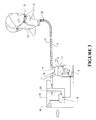
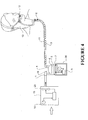
- An example of an embodiment of the breathing circuit which contains multiple RFID tags is shown in Figure 3 .
- the breathing circuit also includes an RFID tag 21 located at the patient end of the conduit 3 and an RFID tag 22 located at the interface end of the conduit 3.
- the tags 2, 21 and 22 are configured as temperature sensors, and additionally tag 2 and one of tags 21 or 22 is configured as an identification tag. It should be noted that these additional tags could be otherwise configured to measure other parameters, or they could be placed at other locations in the breathing circuit as required.
- RFID tags of the passive type are intended to be used or read over very short distances, in the region of 10cm, for example.
- Patient conduits are of standard lengths (e.g. six feet) and blower/humidifier units such as blower unit 15 and chamber 5 are usually located several feet away from a patient (and patient interface) in use. Because the RFID interrogation hardware is therefore usually located several feet away from e.g. RFID tag 2, it can be difficult for the interrogation hardware to receive a consistent and strong data signal, especially if RFID tag 2 is of the passive type and does not include an integral battery or an integral aerial.
- RFID tags which include batteries or aerials can be reliably read over longer distances, but RFID tags of this type are usually larger in size than passive tags and are correspondingly heavier and bulkier. It is desirable to keep the weight of components in the breathing circuit as light as possible, especially at the patient end, so that a patient does not have to carry additional weight or bulk.
- the patient interface 12 is used with a breathing conduit that includes the heater wire 11.
- the RFID tag 2 (in the preferred form embedded or attached to the patient interface 12) is in use connected to the heater wire 11.
- the RFID tag 2 could also be included at the patient end of a stand-alone conduit.
- the heater wire 11 of the conduit 3 is in this embodiment adapted so that it has dual functionality: it acts as a heater wire, and also as an aerial for the RFID tag 2.
- the use of the heater wire 11 as an aerial greatly extends the range of data transmission.
- one end of the heater wire 11 is located at the blower end of the breathing conduit 3, considerably closer to the blower unit 15 than the patient interface 12. Therefore the necessary transmission range is considerably shorter than would otherwise be the case.
- the heater wire 11 as an aerial allows the interrogation hardware located in the housing of the blower unit 15 to interrogate the RFID tag 2 over longer distances - for example 6 feet or more - in real time, without the RFID tag 2 requiring a battery or its own aerial. If a battery or other integral power supply is used, it does not need to be as powerful, and can therefore be smaller than would otherwise be the case.
- the real time temperature data gathered by the RFID tag 2 is fed back to the control circuitry 9 via the RFID interrogation hardware contained in the housing of the blower unit 15.
- a semi-passive or an active tag may be required at the patient interface in some applications - e.g. RFID tag 2 may be required to be of the semi-passive or active type.
- the heater wire 11 can be further adapted so that it supplies power to the RFID tag 2 as well as acting as a heater wire in the conduit 3.
- the blower unit 15 can include manual user controls as well as the automatic adjustment mechanisms described above, where the power output adjustments are made by means of feedback from sensors (e.g. RFID tag 2) located at various points in the system.
- the manual controls can include a user input mechanism such as a switch 10.
- Switch 10 is adapted to allow a user (such as a healthcare professional or the patient themselves) to manually set a desired gases temperature of the gases to be delivered.
- the controls could include a manual adjustment of the desired gases humidity level.
- other functions could also be manually controlled, or alternatively a user or healthcare professional could be given a choice of a number of automatic gases delivery configurations, the user choosing an individual configuration by selecting from a menu or setting the appropriate control.
- the preferred form of RFID tag 2 is configured to act both as a temperature sensor and as a component identifier. It is also possible to use an RFID tag that is adapted to measure one of a number of other parameters. For example, instead of using an RFID tag that is configured to measure temperature, an RFID tag that is configured to measure pressure, or gases flow rate, or gases humidity, or gases content (i.e. oxygen percentage) could be used instead or as well as the RFID tag 2.
- the RFID tag 2 may be used as a patient interface identifier, providing an identification input signal to the control system.
- the identification signal identifies which type of patient interface (or breathing conduit) has been connected to the blower unit (which contains the interrogation hardware).
- the conduit 3 will include a tag at both the humidifier end and at the patient end.
- the tag at the humidifier end carries the identification data - data relating to the identity of the component or the component identity.
- the component identification data can be carried by any component tag.
- the control system contained in the casing of the blower unit is configured to automatically change the output settings in response to the identifier signal received from the RFID tag.
- a number of different "identification profiles" are stored in the memory of the control system 9, each one based around a predetermined required gas temperature and humidity value. Each of these profiles corresponds to an RFID identification code for tags embedded in different types of patient interface.
- the transceiver or interrogation hardware polls continuously until it receives an identification code from the RFID tag 2.
- the returning identification code tag data information is compared to the stored "identification profiles" and the control system automatically sets the humidifier gas temperature and humidity output levels.
- this humidification control system can be overridden by a user manually adjusting a switch input.
- the advantage of this system over other systems known in the art is that user error is eliminated.
- the setting of the user operational mode is not dependent on user input.
- the RFID tags embedded in components such as the conduit 3 can carry component expiry date data.
- the control system 9 reads the RFID tag and compares the present date with the expiry date. If the expiry date has passed, the control system 9 can alert the user by means of an audio or visual alarm, or refuse to activate the system, or similar.
- RFID tag 2 is constructed on a piezo-electric crystal element.
- the RFID tag 2 is preferably located on or within the patient interface 12 or heated inspiratory conduit 3, in close proximity to the patient 13.
- the piezo-electric element geometric shape is configured prior to use so that when it is interrogated, it provides a means of identifying the type of patient interface to which the RFID is being attached, and also acts as a sensor - e.g. a temperature sensor, a pressure sensor, etc).
- the preferred type of RFID tag and means of interrogation is by using surface acoustic wave (SAW) technology, where the properties of the returning wave will differ from the transmitted wave, and can therefore be used to measure temperature, pressure, flow, gas composition, etc. as detailed below.
- SAW surface acoustic wave
- the piezo-electric crystal elements provide a means of sensing gas parameters (such as temperature) at the point of delivery to the patient 13.
- the interrogation hardware polls the RFID 2 at predetermined intervals of time.
- the RFID tag can be energised by this incoming radio wave from the interrogation hardware.
- a pulse train passes across the surface of the crystal and a modulated pulse train is returned to the interrogation hardware in control system 9.
- a transceiver in the interrogation hardware decodes the pulse train and uses a lookup table located in the memory of control system 9 to determine the appropriate gas parameter (e.g. temperature).
- the parameter retrieved from the lookup table is compared with the required parameter value (e.g. temperature) for the current configuration. For example, the measured temperature is compared with the "identification profile" for the particular patient interface and the particular treatment regime specified. If there is a difference in the two values, then a control signal is generated by the control system, and the output parameters of the breathing circuit are adjusted accordingly. For example, if the RFID tag 2 is configured to measure the temperature, and the measured temperature is too low in comparison to the retrieved lookup value, the control system increases the power to the heater plate, so that the heated, humidified gases leaving the humidifier are at a higher temperature.
- the required parameter value e.g. temperature
- RFID tags described above are the passive type. Semi-passive or active RFID tags can also be used if required. If an active-type RFID tag is used, it does not have to be powered by using the heater wire, it can be provided with its own power source such as a battery.
- the RFID tag such as tag 2 could also be a microprocessor device, and could include a wireless transmitter and receiver, with (if required) its own power supply. For example, the RFID tag 2 could be replaced with a Bluetooth-type device, or any other active type of transmitter which uses wireless communication. If it would be appropriate to do so, the phrase "RFID tag" should be read broadly enough to cover these types of devices. However, passive RFID tags are the preferred form.
- the RFID interrogator and the control system 9 are located inside the housing of the blower unit 15.
- modular components for example a separate blower and humidifier unit, with the outlet of the blower unit and the inlet of the humidifier chamber connected in use by a separate conduit so that the gases stream from the blower unit can be delivered to the humidifier chamber.
- the humidifier part of the breathing circuit includes a base unit 30, which the humidifier chamber 5 locates onto in use, the base unit including a heater plate which heats the contents of the humidifier chamber 5.
- the control system 9 and the RFID interrogator can be located either in the base unit 30 or (if a blower unit is used to form the breathing circuit), in the blower unit, as required.
- the base unit can be used in a hospital which includes built-in gas supply conduits or gas sources. These are usually located in the hospital walls.
- the base unit 30 in these situations would contain the RFID interrogator and control system 9.
- a conduit would connect the hospital gases supply to the inlet of the humidifier chamber.
- the hospital gases supply would act as a source of pressurised gases.
- breathing conduits or gases conduits can be formed and sold separately for use as a part of a breathing circuit which delivers heated, humidified gases to a patient for medical purposes.
- the breathing conduits would have a first end adapted for connection to the outlet of a humidifier chamber, and a second, patient end, which would include an RFID tag, the RFID tag adapted to sense a parameter of the gases passing through said gases transportation pathway, in a similar manner to that described above.
Claims (14)
- Unité de base destinée à être utilisée en tant que partie d'un circuit respiratoire qui fournit des gaz chauffés humidifiés à un patient à des fins médicales, ladite unité de base comprenant :une plaque chauffante (7) adaptée pour permettre de placer une chambre d'humidificateur (5) en cours d'utilisation sur ladite plaque chauffante (7) de sorte que ladite plaque chauffante (7) chauffe une quantité d'eau (6) dans ladite chambre d'humidificateur (5) et de réchauffer et d'humidifier les gaz circulant dans ladite chambre d'humidificateur (5) ; etun système de commande (9) configuré pour régler un ou plusieurs paramètres de sortie dudit circuit respiratoire caractérisé en ce que :
ledit système de commande comprend un interrogateur RFID configuré pour interroger et recevoir des données d'au moins une étiquette RFID (2) en temps réel, les données de ladite étiquette RFID étant relatives à :au moins un paramètre détecté des gaz circulant dans le circuit respiratoire,etl'identité d'au moins un composant dans ledit circuit respiratoire comprenant une étiquette RFID (2),dans laquelle un ou plusieurs des paramètres de sortie dudit circuit respiratoire sont réglables par ledit système de commande (9) selon les données reçues de ladite étiquette RFID. - Un système comprenant l'unité de base de la revendication 1 et au moins un composant d'un circuit respiratoire, le composant comprenant au moins une étiquette RFID fixée ou intégrée (2), dans lequel :ladite au moins une étiquette RFID (2) comprend des données relatives à l'identité d'au moins un composant dans le circuit respiratoire, ladite étiquette RFID intégrée (2) identifiant le, au moins un, composant individuel du circuit respiratoire lorsqu'elle est interrogée par l'interrogateur RFID ; etau moins une desdites étiquettes RFID fixées ou intégrées (2) est adaptée pour mesurer un paramètre de gaz circulant dans le circuit respiratoire.
- Unité de base selon la revendication 1 ou le système selon la revendication 2, où ledit au moins un paramètre détecté est mesuré par ladite au moins une étiquette RFID (2).
- Unité de base ou système selon l'une quelconque des revendications précédentes, où ladite au moins une étiquette RFID (2) est configurée pour mesurer et fournir des données relatives à l'une quelconque parmi ou une combinaison de : la température des gaz, la pression des gaz, le débit des gaz, l'humidité des gaz et la teneur en oxygène des gaz ; et/ou
où un ou plusieurs des paramètres de sortie réglé(s) par ledit système de commande (9) comprend/comprennent l'une quelconque ou une combinaison parmi : la vitesse du ventilateur, la puissance de sortie de la plaque chauffante et la puissance de sortie du fil chauffant du tube respiratoire. - Unité de base ou système selon l'une quelconque des revendication précédentes, où ledit système de commande (9) comprend un certain nombre de profils d'identification prédéfinis et, en cours d'utilisation, ledit interrogateur RFID est adapté pour recevoir des données de ladite au moins une étiquette RFID (2) relatives à l'identité dudit au moins un composant dans ledit circuit respiratoire et ledit système de commande (9) est configuré pour comparer lesdites données relatives à l'identité dudit au moins un composant auxdits un ou plusieurs profils d'identification prédéfinis et régler automatiquement les valeurs initiales desdits paramètres de sortie en fonction d'un ou de plusieurs desdits composants identifiés.
- Unité de base ou système selon l'une quelconque des revendications précédentes, où ladite au moins une étiquette RFID (2) porte des données de date d'expiration pour ledit au moins un composant dans ledit circuit respiratoire.
- Unité de base ou système selon l'une quelconque des revendications précédentes, où ladite unité de base comprend une commande actionnable par l'utilisateur adaptée pour permettre à un utilisateur de définir des paramètres de sortie dudit circuit respiratoire.
- Unité de base selon la revendication 7, dans laquelle lesdits paramètres de sortie sont l'un ou les deux parmi la température des gaz et l'humidité des gaz.
- Unité de base ou système selon la revendication 6, où ledit système de commande (9) est adapté pour comparer la date actuelle à ladite date d'expiration et déclencher une condition d'alarme en cas de dépassement de ladite date d'expiration.
- Unité de base ou système selon la revendication 9, où ledit système de commande est aussi adapté pour alerter un utilisateur du dépassement de ladite date d'expiration au moyen d'une alarme sonore ou visuelle.
- Unité de base ou système selon la revendication 9 ou la revendication 10, où ledit système de commande est aussi adapté pour alerter un utilisateur en cas de dépassement de ladite date d'expiration en refusant d'activer le circuit respiratoire.
- Unité de base ou système selon l'une quelconque des revendications précédentes, où l'unité de base fait partie d'un circuit respiratoire comprenant une source de gaz sous pression, ladite source de gaz sous pression étant séparée de ladite unité de base.
- Unité de base ou système selon l'une quelconque des revendications précédentes, où ladite au moins une étiquette RFID (2) se situe à un ou plusieurs emplacements quelconque(s) parmi : une sortie de la chambre de l'humidificateur, une extrémité patient d'un tube et dans une interface patient (12).
- Unité de base ou système selon l'une quelconque des revendications précédentes, où ledit circuit respiratoire est du type comprenant une chambre d'humidificateur (5) adaptée pour contenir une quantité d'eau (6) et ayant une entrée (16) et une sortie (4) pour permettre aux gaz de circuler dans ladite chambre d'humidificateur (5), une source de gaz sous pression qui, en cours d'utilisation, sont fournis à l'entrée (16) de ladite chambre d'humidificateur (5), et une voie de transport de gaz (3) reliée à ladite sortie (4) de ladite chambre d'humidificateur (5) pour transporter ledit flux de gaz vers ledit patient (13), ladite voie de transport de gaz (3) comprenant une interface patient (12) adaptée pour fournir audit patient (3) ledit flux de gaz.
Priority Applications (1)
| Application Number | Priority Date | Filing Date | Title |
|---|---|---|---|
| EP20161498.9A EP3721931B1 (fr) | 2007-01-23 | 2008-01-23 | Conduit de gaz avec un fil chauffant intégré faisant office d'antenne rfid |
Applications Claiming Priority (3)
| Application Number | Priority Date | Filing Date | Title |
|---|---|---|---|
| NZ55278507 | 2007-01-23 | ||
| EP08723997.6A EP2111248B1 (fr) | 2007-01-23 | 2008-01-23 | Humidicateur avec un capteur rfid |
| PCT/NZ2008/000007 WO2008091164A1 (fr) | 2007-01-23 | 2008-01-23 | Système de détection |
Related Parent Applications (2)
| Application Number | Title | Priority Date | Filing Date |
|---|---|---|---|
| EP08723997.6A Division EP2111248B1 (fr) | 2007-01-23 | 2008-01-23 | Humidicateur avec un capteur rfid |
| EP08723997.6A Division-Into EP2111248B1 (fr) | 2007-01-23 | 2008-01-23 | Humidicateur avec un capteur rfid |
Related Child Applications (1)
| Application Number | Title | Priority Date | Filing Date |
|---|---|---|---|
| EP20161498.9A Division EP3721931B1 (fr) | 2007-01-23 | 2008-01-23 | Conduit de gaz avec un fil chauffant intégré faisant office d'antenne rfid |
Publications (2)
| Publication Number | Publication Date |
|---|---|
| EP3088031A1 EP3088031A1 (fr) | 2016-11-02 |
| EP3088031B1 true EP3088031B1 (fr) | 2020-03-18 |
Family
ID=39644686
Family Applications (3)
| Application Number | Title | Priority Date | Filing Date |
|---|---|---|---|
| EP16158954.4A Active EP3088031B1 (fr) | 2007-01-23 | 2008-01-23 | Humidicateur avec un capteur rfid |
| EP20161498.9A Active EP3721931B1 (fr) | 2007-01-23 | 2008-01-23 | Conduit de gaz avec un fil chauffant intégré faisant office d'antenne rfid |
| EP08723997.6A Active EP2111248B1 (fr) | 2007-01-23 | 2008-01-23 | Humidicateur avec un capteur rfid |
Family Applications After (2)
| Application Number | Title | Priority Date | Filing Date |
|---|---|---|---|
| EP20161498.9A Active EP3721931B1 (fr) | 2007-01-23 | 2008-01-23 | Conduit de gaz avec un fil chauffant intégré faisant office d'antenne rfid |
| EP08723997.6A Active EP2111248B1 (fr) | 2007-01-23 | 2008-01-23 | Humidicateur avec un capteur rfid |
Country Status (5)
| Country | Link |
|---|---|
| US (3) | US10124141B2 (fr) |
| EP (3) | EP3088031B1 (fr) |
| CN (3) | CN103432671B (fr) |
| AU (1) | AU2008208148B2 (fr) |
| WO (1) | WO2008091164A1 (fr) |
Families Citing this family (64)
| Publication number | Priority date | Publication date | Assignee | Title |
|---|---|---|---|---|
| EP3088031B1 (fr) | 2007-01-23 | 2020-03-18 | Fisher & Paykel Healthcare Limited | Humidicateur avec un capteur rfid |
| EP2149109A4 (fr) | 2007-05-18 | 2014-01-01 | 3M Innovative Properties Co | Procédé pour suivre des procédures effectuées sur un équipement de protection personnel, et des actions d'individus |
| AU2008254398B2 (en) | 2007-05-18 | 2010-07-15 | 3M Innovative Properties Company | Method for tracking cyclical procedures performed on personal protection equipment |
| PL2183030T3 (pl) | 2007-08-31 | 2017-09-29 | 3M Innovative Properties Company | Ustalanie stanu komponentów połączonych rozłącznie ze środkami ochrony indywidualnej |
| WO2009051896A2 (fr) | 2007-08-31 | 2009-04-23 | 3M Innovative Properties Company | Détermination de l'état d'articles de protection individuelle selon au moins un critère |
| AU2008296768B2 (en) * | 2007-08-31 | 2011-06-02 | 3M Innovative Properties Company | Tracking compliance of personal protection articles |
| US20090058600A1 (en) | 2007-08-31 | 2009-03-05 | 3M Innovative Properties Company | Determining compatibility of components for assembling approved personal protection configurations |
| EP3075406A1 (fr) | 2008-04-30 | 2016-10-05 | ResMed R&D Germany GmbH | Appareil et procédé pour l'administration contrôlée d'un gaz respiratoire dans les voies respiratoires d'un utilisateur |
| NZ618492A (en) | 2008-06-05 | 2015-09-25 | Resmed Ltd | Treatment of respiratory conditions |
| AU2010206053B2 (en) * | 2009-07-31 | 2014-08-07 | ResMed Pty Ltd | Wire Heated Tube with Temperature Control System, Tube Type Detection, and Active Over Temperature Protection for Humidifier for Respiratory Apparatus |
| DE102009038635B4 (de) * | 2009-08-26 | 2015-02-19 | F. Stephan Gmbh Medizintechnik | Vorrichtung zur Atemgasbefeuchtung |
| EP2295095A1 (fr) | 2009-09-10 | 2011-03-16 | F. Hoffmann-La Roche AG | Perfuseur comportant un écran d'affichage de données |
| JP5795764B2 (ja) * | 2009-09-11 | 2015-10-14 | コーニンクレッカ フィリップス エヌ ヴェ | ワイヤレス温度検出を用いる加湿器 |
| US9278184B2 (en) | 2009-10-28 | 2016-03-08 | Koninklijke Philips N.V. | Pressure support system with inductive tubing |
| JP5795590B2 (ja) * | 2009-11-03 | 2015-10-14 | コーニンクレッカ フィリップス エヌ ヴェ | 呼吸をモニタするシステム及び方法 |
| EP2496297B1 (fr) | 2009-11-03 | 2020-09-16 | ResMed Pty Ltd | Systèmes de ventilation spontanée en pression positive continue |
| WO2011058462A2 (fr) * | 2009-11-11 | 2011-05-19 | Koninklijke Philips Electronics N.V. | Identification sans fil d'une composante d'un système de support de pression |
| ES2939556T3 (es) | 2009-12-01 | 2023-04-24 | Fisher & Paykel Healthcare Ltd | Aparato de asistencia respiratoria |
| WO2011077274A1 (fr) * | 2009-12-21 | 2011-06-30 | Koninklijke Philips Electronics N.V. | Identification automatique d'un dispositif d'interface de patient dans un système de support de pression |
| US9572951B2 (en) | 2010-04-27 | 2017-02-21 | Fisher & Paykel Healthcare Limited | Apparatus for supplying gases to a patient |
| CN101976369A (zh) * | 2010-08-03 | 2011-02-16 | 苏州博康生物医疗科技有限公司 | 一种针灸治疗用的rfid标签 |
| WO2012045051A1 (fr) * | 2010-09-30 | 2012-04-05 | Breathe Technologies, Inc. | Procédés, systèmes et dispositifs d'humidification de voies respiratoires |
| JP2014506486A (ja) | 2011-01-24 | 2014-03-17 | レスメド・リミテッド | 加湿器 |
| GB2495771B (en) * | 2011-10-21 | 2018-07-04 | Intersurgical Ag | System for controlling delivery of respiratory gas |
| US10806878B2 (en) | 2012-02-22 | 2020-10-20 | Koninklijke Philips N.V. | System and method for determining a target subject interface temperature based on a baseline temperature |
| EP3738638A1 (fr) | 2012-03-15 | 2020-11-18 | Fisher & Paykel Healthcare Limited | Système d'humidification de gaz respiratoire |
| US20130255670A1 (en) * | 2012-04-02 | 2013-10-03 | Lexion Medical, Llc | System and Method for Performing a Surgical Procedure |
| EP3446737B8 (fr) * | 2012-04-05 | 2021-12-22 | Fisher & Paykel Healthcare Limited | Appareil d'assistance respiratoire |
| IN2014MN02333A (fr) | 2012-04-27 | 2015-08-14 | Fisher & Paykel Healthcare Ltd | |
| CN104411355B (zh) | 2012-05-02 | 2017-11-03 | 费雪派克医疗保健有限公司 | 呼吸加湿器通信系统和方法 |
| DE102012215789A1 (de) * | 2012-09-06 | 2014-03-06 | Krones Ag | Rüstteil mit Identifikationselement |
| NZ727820A (en) | 2013-02-01 | 2018-06-29 | Resmed Ltd | Wire heated tube with temperature control system for humidifier for respiratory apparatus |
| CN105188821B (zh) * | 2013-03-15 | 2020-01-07 | 费雪派克医疗保健有限公司 | 用于医疗回路的组件 |
| US10342942B2 (en) * | 2013-03-15 | 2019-07-09 | Fisher & Paykel Healthcare Limited | Respiratory assistance device and method of controlling said device |
| US20140305930A1 (en) * | 2013-04-10 | 2014-10-16 | Craig Heizer | Heating Cable Having An RFID Device |
| WO2014169146A1 (fr) * | 2013-04-10 | 2014-10-16 | Pentair Thermal Management Llc | Isolation thermique ayant un dispositif rfid |
| US11517689B2 (en) * | 2013-08-05 | 2022-12-06 | Fisher & Paykel Healthcare Limited | Control for respiratory device |
| CA3166029A1 (fr) | 2013-09-13 | 2015-03-19 | Fisher And Paykel Healthcare Limited | Connecteur de circuits pour systeme d'humidification |
| EP3043854B1 (fr) * | 2013-09-13 | 2019-11-06 | Fisher & Paykel Healthcare Limited | Système d'humidification |
| CA3176263A1 (fr) | 2013-12-20 | 2015-06-25 | Fisher & Paykel Healthcare Limited | Raccordements de systeme d'humification |
| US10449319B2 (en) | 2014-02-07 | 2019-10-22 | Fisher & Paykel Healthcare Limited | Respiratory humidification system |
| WO2015167347A1 (fr) | 2014-05-02 | 2015-11-05 | Fisher & Paykel Healthcare Limited | Dispositif d'humidification de gaz |
| US20150320592A1 (en) * | 2014-05-09 | 2015-11-12 | Scion Neurostim, Llc | Devices, Systems and Methods for Delivering Thermal Stimulation |
| AU2015259944B2 (en) | 2014-05-13 | 2020-07-02 | Fisher & Paykel Healthcare Limited | Usability features for respiratory humidification system |
| EP3151894B1 (fr) | 2014-06-03 | 2019-08-28 | Fisher & Paykel Healthcare Limited | Mélangeurs d'écoulement pour des systèmes de thérapie respiratoire |
| EP3925654B1 (fr) | 2014-11-17 | 2024-04-17 | Fisher & Paykel Healthcare Limited | Humidification de gaz respiratoires |
| WO2016094423A1 (fr) | 2014-12-09 | 2016-06-16 | Flexicare, Inc. | Systèmes et procédés pour chauffer et humidifier des gaz inspirés au cours d'une ventilation mécanique |
| EP3313491B1 (fr) | 2015-06-25 | 2019-03-06 | Maquet Critical Care AB | Augmentation d'oxygène pendant la ventilation mécanique d'un patient |
| DE102015216895A1 (de) | 2015-09-03 | 2017-03-09 | Hamilton Medical Ag | Beatmungsvorrichtung mit Fehlererfassung für Durchflusssensoren |
| WO2017126980A2 (fr) * | 2016-01-18 | 2017-07-27 | Fisher & Paykel Healthcare Limited | Humidification de gaz respiratoires |
| CN109862933B (zh) * | 2016-09-16 | 2022-03-18 | 菲舍尔和佩克尔保健有限公司 | 具有多个温度点的热敏电阻器流量传感器 |
| GB2601711B (en) | 2016-10-11 | 2022-11-30 | Fisher & Paykel Healthcare Ltd | Method of detecting errors in the connections in a humidification system |
| WO2018081872A1 (fr) * | 2016-11-07 | 2018-05-11 | Resmed Limited | Conduit pour appareil de thérapie respiratoire |
| EP3551978B1 (fr) | 2016-12-07 | 2022-01-26 | Fisher&Paykel Healthcare Limited | Agencements de détection pour dispositifs médicaux |
| WO2019025340A1 (fr) * | 2017-08-04 | 2019-02-07 | Koninklijke Philips N.V. | Masque et procédé de commande |
| NL2019418B1 (en) * | 2017-08-15 | 2019-02-25 | Van Woerkum Holding B V | Portable air treatment device and method for supplying filtered air to a person |
| JP7056911B2 (ja) * | 2018-02-19 | 2022-04-19 | 株式会社メトラン | 高流量ガス送気装置 |
| CN108578866A (zh) * | 2018-03-22 | 2018-09-28 | 左汉恒 | 一种心内科的吸氧装置 |
| CN112135653A (zh) * | 2018-05-14 | 2020-12-25 | 柯惠有限合伙公司 | 用于通气加湿的系统和方法 |
| DE102018009804B4 (de) * | 2018-12-18 | 2021-02-04 | Dräger Safety AG & Co. KGaA | Kontrollsystem und Verfahren zur Kontrolle eines Atemgaskreislaufs in einem Kreislaufatemschutzgerät |
| CN109464735A (zh) * | 2018-12-28 | 2019-03-15 | 乔璋晓 | 一种基于自主控制通气模式下的呼吸机 |
| JP2023515627A (ja) * | 2020-02-27 | 2023-04-13 | フィッシャー アンド ペイケル ヘルスケア リミテッド | ガス流の供給に関連する改善 |
| CA3173212A1 (fr) * | 2020-04-29 | 2021-11-04 | Wenjie Robin LIANG | Humidificateur respiratoire ou chirurgical et procede d'utilisation |
| CN113679924B (zh) * | 2021-08-30 | 2024-01-02 | 可孚医疗科技股份有限公司 | 一种用于呼吸设备的加湿水箱的水温控制方法及相应装置 |
Citations (1)
| Publication number | Priority date | Publication date | Assignee | Title |
|---|---|---|---|---|
| US20060278221A1 (en) * | 2005-06-08 | 2006-12-14 | Drager Medical Ag & Co. Kg | Process and device for the automatic identification of breathing tubes |
Family Cites Families (46)
| Publication number | Priority date | Publication date | Assignee | Title |
|---|---|---|---|---|
| EP0535952B1 (fr) * | 1991-10-04 | 1997-12-29 | FISHER & PAYKEL LIMITED | Humidificateur |
| US6748797B2 (en) * | 2000-09-08 | 2004-06-15 | Automotive Technologies International Inc. | Method and apparatus for monitoring tires |
| CA2240812C (fr) * | 1997-06-17 | 2004-06-01 | Fisher & Paykel Limited | Systeme d'humidification pour appareillage respiratoire |
| US6485462B1 (en) * | 1997-08-27 | 2002-11-26 | Science Incorporated | Fluid delivery device with heat activated energy source |
| US6107611A (en) * | 1998-01-19 | 2000-08-22 | Msx, Inc. | Method and apparatus for detecting ground faults in a shielded heater wire by sensing electrical arcing |
| AU3508799A (en) | 1998-06-19 | 2000-01-06 | Fisher & Paykel Healthcare Limited | Humidified sleep apnea treatment apparatus |
| US6918389B2 (en) * | 2000-03-21 | 2005-07-19 | Fisher & Paykel Healthcare Limited | Breathing assistance apparatus |
| EP1301230A1 (fr) | 2000-07-15 | 2003-04-16 | Glaxo Group Limited | Distributeur de medicaments |
| JP4180367B2 (ja) * | 2000-10-16 | 2008-11-12 | フィッシャー アンド ペイケル ヘルスケア リミテッド | 医療処置でガスの加湿に使用する装置 |
| US6357438B1 (en) * | 2000-10-19 | 2002-03-19 | Mallinckrodt Inc. | Implantable sensor for proportional assist ventilation |
| US20020139368A1 (en) * | 2001-03-29 | 2002-10-03 | Bachinski Thomas J. | Oxygen sensor mounting in medical or flight crew masks for direct indication of blood level oxygen |
| DE10139881B4 (de) | 2001-08-20 | 2017-06-08 | Resmed R&D Germany Gmbh | Vorrichtung zur Zufuhr eines Atemgases und Verfahren zur Steuerung derselben |
| US8085144B2 (en) * | 2002-07-02 | 2011-12-27 | Mine Safety Appliances Company | Equipment and method for identifying, monitoring and evaluating equipment, environmental and physiological conditions |
| JP4709547B2 (ja) * | 2002-08-30 | 2011-06-22 | フィッシャー アンド ペイケル ヘルスケア リミテッド | 加湿システム |
| US20040100376A1 (en) * | 2002-11-26 | 2004-05-27 | Kimberly-Clark Worldwide, Inc. | Healthcare monitoring system |
| US7101341B2 (en) * | 2003-04-15 | 2006-09-05 | Ross Tsukashima | Respiratory monitoring, diagnostic and therapeutic system |
| AU2003903139A0 (en) * | 2003-06-20 | 2003-07-03 | Resmed Limited | Breathable gas apparatus with humidifier |
| US7115097B2 (en) * | 2003-10-09 | 2006-10-03 | Johnson Joseph L | Positive airway pressure notification system for treatment of breathing disorders during sleep |
| WO2005053542A1 (fr) * | 2003-12-01 | 2005-06-16 | Sierra Medical Technology, Inc. | Systeme de surveillance, de diagnostic et de traitement respiratoire |
| US7148806B2 (en) * | 2004-03-25 | 2006-12-12 | Ge Healthcare Finland Oy | Arrangement in connection with a patient circuit and an absorber means |
| US20050228238A1 (en) * | 2004-04-09 | 2005-10-13 | Arnold Monitzer | Patient parameter automatic acquisition system |
| DE102004023385A1 (de) * | 2004-04-29 | 2005-11-24 | Helmut Assmann | Beatmungssystem sowie beheizbare Schlauchanordnung mit Temperatursensor für ein Beatmungssystem |
| US20050277873A1 (en) * | 2004-05-27 | 2005-12-15 | Janice Stewart | Identification information recognition system for a medical device |
| US7128675B2 (en) * | 2004-07-29 | 2006-10-31 | General Motors Corporation | Dual path electrically-variable transmission |
| HUE060036T2 (hu) * | 2004-08-20 | 2023-01-28 | Fisher & Paykel Healthcare Ltd | Berendezés páciensnek szállított gázok tulajdonságainak mérésére |
| US7093479B2 (en) * | 2005-01-13 | 2006-08-22 | International Business Machines Corporation | Method and apparatus for indicating a parameter of transmitted fluid |
| KR100778307B1 (ko) * | 2005-02-07 | 2007-11-22 | (주)씨앤드에스 마이크로 웨이브 | 저 전력 리더-태그 통신을 위한 지능형 무선주파수인식시스템 및 그 방법 |
| TWI250866B (en) * | 2005-03-21 | 2006-03-11 | Ind Tech Res Inst | Flexible equipment for monitoring vital signals |
| US20060250259A1 (en) | 2005-03-25 | 2006-11-09 | Semiconductor Energy Laboratory Co., Ltd. | Monitoring device, care receiver monitoring device, care managing device, care giver terminal device, and care support system and care support method using these |
| DE202005008156U1 (de) * | 2005-05-21 | 2006-10-05 | GRÜNDLER GmbH | Einweg-Heizschlauch mit integriertem Temperatursensor |
| US8677994B2 (en) | 2005-06-08 | 2014-03-25 | Dräger Medical GmbH | Multipart medical engineering system |
| US20060283465A1 (en) * | 2005-06-16 | 2006-12-21 | Nickel Janice H | Smart drug delivery system and a method of implementation thereof |
| WO2007014053A2 (fr) * | 2005-07-22 | 2007-02-01 | Nanopower Technologies, Inc. | Circuits integres d'etiquette rfid a sensibilite elevee |
| DE102005045720B3 (de) * | 2005-09-24 | 2007-01-04 | Dräger Medical AG & Co. KG | Verfahren und Vorrichtung zum Betreiben eines Beatmungssystems |
| US7567179B2 (en) * | 2005-10-17 | 2009-07-28 | Reva Systems Corporation | Configuration management system and method for use in an RFID system including a multiplicity of RFID readers |
| US20070093697A1 (en) * | 2005-10-21 | 2007-04-26 | Theranova, Llc | Method and apparatus for detection of right to left shunting in the cardiopulmonary vasculature |
| US7913689B2 (en) * | 2005-12-21 | 2011-03-29 | Resmed Limited | Identification system and method for mask and ventilator components |
| WO2007081741A2 (fr) | 2006-01-04 | 2007-07-19 | Massachusetts Institute Of Technology | Système de surveillance de circulation de fluide sans fil implantable |
| US8653482B2 (en) * | 2006-02-21 | 2014-02-18 | Goji Limited | RF controlled freezing |
| US7980245B2 (en) * | 2006-05-12 | 2011-07-19 | The General Electric Company | Informative accessories |
| CN101541367B (zh) * | 2006-11-08 | 2014-02-26 | 雷斯梅德有限公司 | 在呼吸装置中使用的导管 |
| EP3088031B1 (fr) | 2007-01-23 | 2020-03-18 | Fisher & Paykel Healthcare Limited | Humidicateur avec un capteur rfid |
| JP2008301847A (ja) * | 2007-06-05 | 2008-12-18 | Canon Inc | 吸入装置及びその駆動方法 |
| JP5795764B2 (ja) * | 2009-09-11 | 2015-10-14 | コーニンクレッカ フィリップス エヌ ヴェ | ワイヤレス温度検出を用いる加湿器 |
| AU2011276504A1 (en) * | 2010-06-28 | 2013-01-24 | Palliatech | Vaporizable substance drug delivery and monitoring system |
| US9205220B2 (en) * | 2011-09-30 | 2015-12-08 | Carefusion 207, Inc. | Fluted heater wire |
-
2008
- 2008-01-23 EP EP16158954.4A patent/EP3088031B1/fr active Active
- 2008-01-23 EP EP20161498.9A patent/EP3721931B1/fr active Active
- 2008-01-23 CN CN201310303173.6A patent/CN103432671B/zh active Active
- 2008-01-23 CN CN2008800091501A patent/CN101641130B/zh active Active
- 2008-01-23 WO PCT/NZ2008/000007 patent/WO2008091164A1/fr active Application Filing
- 2008-01-23 EP EP08723997.6A patent/EP2111248B1/fr active Active
- 2008-01-23 US US12/524,251 patent/US10124141B2/en active Active
- 2008-01-23 CN CN201310303228.3A patent/CN103432672B/zh active Active
- 2008-01-23 AU AU2008208148A patent/AU2008208148B2/en active Active
-
2018
- 2018-10-10 US US16/157,002 patent/US11351328B2/en active Active
-
2022
- 2022-05-04 US US17/662,041 patent/US20220339390A1/en active Pending
Patent Citations (1)
| Publication number | Priority date | Publication date | Assignee | Title |
|---|---|---|---|---|
| US20060278221A1 (en) * | 2005-06-08 | 2006-12-14 | Drager Medical Ag & Co. Kg | Process and device for the automatic identification of breathing tubes |
Also Published As
| Publication number | Publication date |
|---|---|
| EP3721931B1 (fr) | 2022-04-06 |
| US20110088693A1 (en) | 2011-04-21 |
| WO2008091164A1 (fr) | 2008-07-31 |
| AU2008208148A1 (en) | 2008-07-31 |
| EP3721931A1 (fr) | 2020-10-14 |
| US10124141B2 (en) | 2018-11-13 |
| EP2111248A4 (fr) | 2012-01-04 |
| EP3088031A1 (fr) | 2016-11-02 |
| EP2111248B1 (fr) | 2016-04-20 |
| CN103432672B (zh) | 2016-08-24 |
| AU2008208148B2 (en) | 2014-04-17 |
| CN101641130A (zh) | 2010-02-03 |
| US20190091437A1 (en) | 2019-03-28 |
| US11351328B2 (en) | 2022-06-07 |
| EP2111248A1 (fr) | 2009-10-28 |
| US20220339390A1 (en) | 2022-10-27 |
| CN103432671A (zh) | 2013-12-11 |
| CN103432672A (zh) | 2013-12-11 |
| CN103432671B (zh) | 2016-12-28 |
| CN101641130B (zh) | 2013-08-21 |
Similar Documents
| Publication | Publication Date | Title |
|---|---|---|
| US11351328B2 (en) | Humidification apparatus having RFID tag sensor at patient end of gas pathway | |
| EP2844326B1 (fr) | Systèmes de communication pour humidificateur respiratoire | |
| JP7445715B2 (ja) | 呼吸補助装置 | |
| EP2475414B1 (fr) | Humidificateur avec détection de température sans fil | |
| US20220211964A1 (en) | Conduit for respiratory therapy apparatus | |
| AU2013206410B2 (en) | Humidification apparatus having rfid tag sensor at patient end of gas pathway |
Legal Events
| Date | Code | Title | Description |
|---|---|---|---|
| PUAI | Public reference made under article 153(3) epc to a published international application that has entered the european phase |
Free format text: ORIGINAL CODE: 0009012 |
|
| AC | Divisional application: reference to earlier application |
Ref document number: 2111248 Country of ref document: EP Kind code of ref document: P |
|
| AK | Designated contracting states |
Kind code of ref document: A1 Designated state(s): AT BE BG CH CY CZ DE DK EE ES FI FR GB GR HR HU IE IS IT LI LT LU LV MC MT NL NO PL PT RO SE SI SK TR |
|
| 17P | Request for examination filed |
Effective date: 20170502 |
|
| RBV | Designated contracting states (corrected) |
Designated state(s): AT BE BG CH CY CZ DE DK EE ES FI FR GB GR HR HU IE IS IT LI LT LU LV MC MT NL NO PL PT RO SE SI SK TR |
|
| STAA | Information on the status of an ep patent application or granted ep patent |
Free format text: STATUS: REQUEST FOR EXAMINATION WAS MADE |
|
| GRAP | Despatch of communication of intention to grant a patent |
Free format text: ORIGINAL CODE: EPIDOSNIGR1 |
|
| STAA | Information on the status of an ep patent application or granted ep patent |
Free format text: STATUS: GRANT OF PATENT IS INTENDED |
|
| INTG | Intention to grant announced |
Effective date: 20181206 |
|
| GRAJ | Information related to disapproval of communication of intention to grant by the applicant or resumption of examination proceedings by the epo deleted |
Free format text: ORIGINAL CODE: EPIDOSDIGR1 |
|
| STAA | Information on the status of an ep patent application or granted ep patent |
Free format text: STATUS: REQUEST FOR EXAMINATION WAS MADE |
|
| GRAP | Despatch of communication of intention to grant a patent |
Free format text: ORIGINAL CODE: EPIDOSNIGR1 |
|
| STAA | Information on the status of an ep patent application or granted ep patent |
Free format text: STATUS: GRANT OF PATENT IS INTENDED |
|
| INTC | Intention to grant announced (deleted) | ||
| INTG | Intention to grant announced |
Effective date: 20190429 |
|
| GRAJ | Information related to disapproval of communication of intention to grant by the applicant or resumption of examination proceedings by the epo deleted |
Free format text: ORIGINAL CODE: EPIDOSDIGR1 |
|
| STAA | Information on the status of an ep patent application or granted ep patent |
Free format text: STATUS: REQUEST FOR EXAMINATION WAS MADE |
|
| GRAP | Despatch of communication of intention to grant a patent |
Free format text: ORIGINAL CODE: EPIDOSNIGR1 |
|
| STAA | Information on the status of an ep patent application or granted ep patent |
Free format text: STATUS: GRANT OF PATENT IS INTENDED |
|
| INTC | Intention to grant announced (deleted) | ||
| INTG | Intention to grant announced |
Effective date: 20191002 |
|
| GRAS | Grant fee paid |
Free format text: ORIGINAL CODE: EPIDOSNIGR3 |
|
| GRAA | (expected) grant |
Free format text: ORIGINAL CODE: 0009210 |
|
| STAA | Information on the status of an ep patent application or granted ep patent |
Free format text: STATUS: THE PATENT HAS BEEN GRANTED |
|
| AC | Divisional application: reference to earlier application |
Ref document number: 2111248 Country of ref document: EP Kind code of ref document: P |
|
| AK | Designated contracting states |
Kind code of ref document: B1 Designated state(s): AT BE BG CH CY CZ DE DK EE ES FI FR GB GR HR HU IE IS IT LI LT LU LV MC MT NL NO PL PT RO SE SI SK TR |
|
| REG | Reference to a national code |
Ref country code: GB Ref legal event code: FG4D |
|
| REG | Reference to a national code |
Ref country code: DE Ref legal event code: R096 Ref document number: 602008062362 Country of ref document: DE |
|
| REG | Reference to a national code |
Ref country code: AT Ref legal event code: REF Ref document number: 1245211 Country of ref document: AT Kind code of ref document: T Effective date: 20200415 Ref country code: IE Ref legal event code: FG4D |
|
| PG25 | Lapsed in a contracting state [announced via postgrant information from national office to epo] |
Ref country code: NO Free format text: LAPSE BECAUSE OF FAILURE TO SUBMIT A TRANSLATION OF THE DESCRIPTION OR TO PAY THE FEE WITHIN THE PRESCRIBED TIME-LIMIT Effective date: 20200618 Ref country code: FI Free format text: LAPSE BECAUSE OF FAILURE TO SUBMIT A TRANSLATION OF THE DESCRIPTION OR TO PAY THE FEE WITHIN THE PRESCRIBED TIME-LIMIT Effective date: 20200318 |
|
| REG | Reference to a national code |
Ref country code: NL Ref legal event code: MP Effective date: 20200318 |
|
| PG25 | Lapsed in a contracting state [announced via postgrant information from national office to epo] |
Ref country code: GR Free format text: LAPSE BECAUSE OF FAILURE TO SUBMIT A TRANSLATION OF THE DESCRIPTION OR TO PAY THE FEE WITHIN THE PRESCRIBED TIME-LIMIT Effective date: 20200619 Ref country code: LV Free format text: LAPSE BECAUSE OF FAILURE TO SUBMIT A TRANSLATION OF THE DESCRIPTION OR TO PAY THE FEE WITHIN THE PRESCRIBED TIME-LIMIT Effective date: 20200318 Ref country code: HR Free format text: LAPSE BECAUSE OF FAILURE TO SUBMIT A TRANSLATION OF THE DESCRIPTION OR TO PAY THE FEE WITHIN THE PRESCRIBED TIME-LIMIT Effective date: 20200318 Ref country code: SE Free format text: LAPSE BECAUSE OF FAILURE TO SUBMIT A TRANSLATION OF THE DESCRIPTION OR TO PAY THE FEE WITHIN THE PRESCRIBED TIME-LIMIT Effective date: 20200318 Ref country code: BG Free format text: LAPSE BECAUSE OF FAILURE TO SUBMIT A TRANSLATION OF THE DESCRIPTION OR TO PAY THE FEE WITHIN THE PRESCRIBED TIME-LIMIT Effective date: 20200618 |
|
| REG | Reference to a national code |
Ref country code: LT Ref legal event code: MG4D |
|
| PG25 | Lapsed in a contracting state [announced via postgrant information from national office to epo] |
Ref country code: NL Free format text: LAPSE BECAUSE OF FAILURE TO SUBMIT A TRANSLATION OF THE DESCRIPTION OR TO PAY THE FEE WITHIN THE PRESCRIBED TIME-LIMIT Effective date: 20200318 |
|
| PG25 | Lapsed in a contracting state [announced via postgrant information from national office to epo] |
Ref country code: PT Free format text: LAPSE BECAUSE OF FAILURE TO SUBMIT A TRANSLATION OF THE DESCRIPTION OR TO PAY THE FEE WITHIN THE PRESCRIBED TIME-LIMIT Effective date: 20200812 Ref country code: EE Free format text: LAPSE BECAUSE OF FAILURE TO SUBMIT A TRANSLATION OF THE DESCRIPTION OR TO PAY THE FEE WITHIN THE PRESCRIBED TIME-LIMIT Effective date: 20200318 Ref country code: CZ Free format text: LAPSE BECAUSE OF FAILURE TO SUBMIT A TRANSLATION OF THE DESCRIPTION OR TO PAY THE FEE WITHIN THE PRESCRIBED TIME-LIMIT Effective date: 20200318 Ref country code: RO Free format text: LAPSE BECAUSE OF FAILURE TO SUBMIT A TRANSLATION OF THE DESCRIPTION OR TO PAY THE FEE WITHIN THE PRESCRIBED TIME-LIMIT Effective date: 20200318 Ref country code: IS Free format text: LAPSE BECAUSE OF FAILURE TO SUBMIT A TRANSLATION OF THE DESCRIPTION OR TO PAY THE FEE WITHIN THE PRESCRIBED TIME-LIMIT Effective date: 20200718 Ref country code: SK Free format text: LAPSE BECAUSE OF FAILURE TO SUBMIT A TRANSLATION OF THE DESCRIPTION OR TO PAY THE FEE WITHIN THE PRESCRIBED TIME-LIMIT Effective date: 20200318 Ref country code: LT Free format text: LAPSE BECAUSE OF FAILURE TO SUBMIT A TRANSLATION OF THE DESCRIPTION OR TO PAY THE FEE WITHIN THE PRESCRIBED TIME-LIMIT Effective date: 20200318 |
|
| REG | Reference to a national code |
Ref country code: AT Ref legal event code: MK05 Ref document number: 1245211 Country of ref document: AT Kind code of ref document: T Effective date: 20200318 |
|
| REG | Reference to a national code |
Ref country code: DE Ref legal event code: R097 Ref document number: 602008062362 Country of ref document: DE |
|
| PLBE | No opposition filed within time limit |
Free format text: ORIGINAL CODE: 0009261 |
|
| STAA | Information on the status of an ep patent application or granted ep patent |
Free format text: STATUS: NO OPPOSITION FILED WITHIN TIME LIMIT |
|
| PG25 | Lapsed in a contracting state [announced via postgrant information from national office to epo] |
Ref country code: ES Free format text: LAPSE BECAUSE OF FAILURE TO SUBMIT A TRANSLATION OF THE DESCRIPTION OR TO PAY THE FEE WITHIN THE PRESCRIBED TIME-LIMIT Effective date: 20200318 Ref country code: DK Free format text: LAPSE BECAUSE OF FAILURE TO SUBMIT A TRANSLATION OF THE DESCRIPTION OR TO PAY THE FEE WITHIN THE PRESCRIBED TIME-LIMIT Effective date: 20200318 Ref country code: AT Free format text: LAPSE BECAUSE OF FAILURE TO SUBMIT A TRANSLATION OF THE DESCRIPTION OR TO PAY THE FEE WITHIN THE PRESCRIBED TIME-LIMIT Effective date: 20200318 Ref country code: IT Free format text: LAPSE BECAUSE OF FAILURE TO SUBMIT A TRANSLATION OF THE DESCRIPTION OR TO PAY THE FEE WITHIN THE PRESCRIBED TIME-LIMIT Effective date: 20200318 |
|
| 26N | No opposition filed |
Effective date: 20201221 |
|
| PG25 | Lapsed in a contracting state [announced via postgrant information from national office to epo] |
Ref country code: PL Free format text: LAPSE BECAUSE OF FAILURE TO SUBMIT A TRANSLATION OF THE DESCRIPTION OR TO PAY THE FEE WITHIN THE PRESCRIBED TIME-LIMIT Effective date: 20200318 |
|
| PG25 | Lapsed in a contracting state [announced via postgrant information from national office to epo] |
Ref country code: SI Free format text: LAPSE BECAUSE OF FAILURE TO SUBMIT A TRANSLATION OF THE DESCRIPTION OR TO PAY THE FEE WITHIN THE PRESCRIBED TIME-LIMIT Effective date: 20200318 |
|
| PG25 | Lapsed in a contracting state [announced via postgrant information from national office to epo] |
Ref country code: MC Free format text: LAPSE BECAUSE OF FAILURE TO SUBMIT A TRANSLATION OF THE DESCRIPTION OR TO PAY THE FEE WITHIN THE PRESCRIBED TIME-LIMIT Effective date: 20200318 |
|
| REG | Reference to a national code |
Ref country code: CH Ref legal event code: PL |
|
| PG25 | Lapsed in a contracting state [announced via postgrant information from national office to epo] |
Ref country code: LU Free format text: LAPSE BECAUSE OF NON-PAYMENT OF DUE FEES Effective date: 20210123 |
|
| REG | Reference to a national code |
Ref country code: BE Ref legal event code: MM Effective date: 20210131 |
|
| PG25 | Lapsed in a contracting state [announced via postgrant information from national office to epo] |
Ref country code: LI Free format text: LAPSE BECAUSE OF NON-PAYMENT OF DUE FEES Effective date: 20210131 Ref country code: CH Free format text: LAPSE BECAUSE OF NON-PAYMENT OF DUE FEES Effective date: 20210131 |
|
| PG25 | Lapsed in a contracting state [announced via postgrant information from national office to epo] |
Ref country code: IE Free format text: LAPSE BECAUSE OF NON-PAYMENT OF DUE FEES Effective date: 20210123 |
|
| PG25 | Lapsed in a contracting state [announced via postgrant information from national office to epo] |
Ref country code: BE Free format text: LAPSE BECAUSE OF NON-PAYMENT OF DUE FEES Effective date: 20210131 |
|
| PG25 | Lapsed in a contracting state [announced via postgrant information from national office to epo] |
Ref country code: HU Free format text: LAPSE BECAUSE OF FAILURE TO SUBMIT A TRANSLATION OF THE DESCRIPTION OR TO PAY THE FEE WITHIN THE PRESCRIBED TIME-LIMIT; INVALID AB INITIO Effective date: 20080123 Ref country code: CY Free format text: LAPSE BECAUSE OF FAILURE TO SUBMIT A TRANSLATION OF THE DESCRIPTION OR TO PAY THE FEE WITHIN THE PRESCRIBED TIME-LIMIT Effective date: 20200318 |
|
| PGFP | Annual fee paid to national office [announced via postgrant information from national office to epo] |
Ref country code: DE Payment date: 20221220 Year of fee payment: 16 |
|
| P01 | Opt-out of the competence of the unified patent court (upc) registered |
Effective date: 20230526 |
|
| PGFP | Annual fee paid to national office [announced via postgrant information from national office to epo] |
Ref country code: GB Payment date: 20231219 Year of fee payment: 17 |
|
| PGFP | Annual fee paid to national office [announced via postgrant information from national office to epo] |
Ref country code: FR Payment date: 20231219 Year of fee payment: 17 |