EP3087924A1 - Device for detecting x-rays inside mouth - Google Patents
Device for detecting x-rays inside mouth Download PDFInfo
- Publication number
- EP3087924A1 EP3087924A1 EP14875605.9A EP14875605A EP3087924A1 EP 3087924 A1 EP3087924 A1 EP 3087924A1 EP 14875605 A EP14875605 A EP 14875605A EP 3087924 A1 EP3087924 A1 EP 3087924A1
- Authority
- EP
- European Patent Office
- Prior art keywords
- unit
- hinge
- cable
- sensor
- intraoral
- Prior art date
- Legal status (The legal status is an assumption and is not a legal conclusion. Google has not performed a legal analysis and makes no representation as to the accuracy of the status listed.)
- Granted
Links
- 230000008878 coupling Effects 0.000 description 20
- 238000010168 coupling process Methods 0.000 description 20
- 238000005859 coupling reaction Methods 0.000 description 20
- 238000003384 imaging method Methods 0.000 description 6
- 230000004048 modification Effects 0.000 description 6
- 238000012986 modification Methods 0.000 description 6
- 230000005855 radiation Effects 0.000 description 6
- 238000006243 chemical reaction Methods 0.000 description 5
- 230000007794 irritation Effects 0.000 description 4
- 239000004020 conductor Substances 0.000 description 2
- 230000000694 effects Effects 0.000 description 2
- 239000012212 insulator Substances 0.000 description 2
- 230000005540 biological transmission Effects 0.000 description 1
- 238000004891 communication Methods 0.000 description 1
- 230000007547 defect Effects 0.000 description 1
- 239000011810 insulating material Substances 0.000 description 1
- 239000007788 liquid Substances 0.000 description 1
- 239000000463 material Substances 0.000 description 1
- 238000000034 method Methods 0.000 description 1
- 239000004065 semiconductor Substances 0.000 description 1
- 230000008054 signal transmission Effects 0.000 description 1
- 239000000758 substrate Substances 0.000 description 1
Images


Classifications
-
- A—HUMAN NECESSITIES
- A61—MEDICAL OR VETERINARY SCIENCE; HYGIENE
- A61B—DIAGNOSIS; SURGERY; IDENTIFICATION
- A61B6/00—Apparatus or devices for radiation diagnosis; Apparatus or devices for radiation diagnosis combined with radiation therapy equipment
- A61B6/50—Apparatus or devices for radiation diagnosis; Apparatus or devices for radiation diagnosis combined with radiation therapy equipment specially adapted for specific body parts; specially adapted for specific clinical applications
- A61B6/51—Apparatus or devices for radiation diagnosis; Apparatus or devices for radiation diagnosis combined with radiation therapy equipment specially adapted for specific body parts; specially adapted for specific clinical applications for dentistry
- A61B6/512—Intraoral means
-
- G—PHYSICS
- G01—MEASURING; TESTING
- G01T—MEASUREMENT OF NUCLEAR OR X-RADIATION
- G01T1/00—Measuring X-radiation, gamma radiation, corpuscular radiation, or cosmic radiation
- G01T1/16—Measuring radiation intensity
- G01T1/161—Applications in the field of nuclear medicine, e.g. in vivo counting
-
- A—HUMAN NECESSITIES
- A61—MEDICAL OR VETERINARY SCIENCE; HYGIENE
- A61B—DIAGNOSIS; SURGERY; IDENTIFICATION
- A61B6/00—Apparatus or devices for radiation diagnosis; Apparatus or devices for radiation diagnosis combined with radiation therapy equipment
- A61B6/42—Arrangements for detecting radiation specially adapted for radiation diagnosis
- A61B6/4208—Arrangements for detecting radiation specially adapted for radiation diagnosis characterised by using a particular type of detector
- A61B6/425—Arrangements for detecting radiation specially adapted for radiation diagnosis characterised by using a particular type of detector using detectors specially adapted to be used in the interior of the body
-
- A—HUMAN NECESSITIES
- A61—MEDICAL OR VETERINARY SCIENCE; HYGIENE
- A61B—DIAGNOSIS; SURGERY; IDENTIFICATION
- A61B6/00—Apparatus or devices for radiation diagnosis; Apparatus or devices for radiation diagnosis combined with radiation therapy equipment
- A61B6/44—Constructional features of apparatus for radiation diagnosis
- A61B6/4429—Constructional features of apparatus for radiation diagnosis related to the mounting of source units and detector units
- A61B6/4452—Constructional features of apparatus for radiation diagnosis related to the mounting of source units and detector units the source unit and the detector unit being able to move relative to each other
Definitions
- This invention relates to an intraoral X-ray detectors and to an intraoral X-ray detector which is freely movable and easily repairable because a cable connecting unit, to which an external cable is attached, is hinge-coupled to be rotatable, to be attachable and detachable to the sensor part.
- intraoral dental information is required to determine the conditions for the treatment of teeth
- X-ray imaging device using the X-rays to obtain an intraoral dental information is provided.
- the X-ray imaging device is comprised of an X-ray irradiator and the X-ray detector for detecting the irradiated X-rays, usually the X-ray irradiated from an outside of a mouth are detected by the X-ray detector inside the mouth.
- the conventional intraoral X-ray detector has a structure that a cable connecting unit 20 to which the external cable 30 is attached and a sensor unit 10 for detecting X-rays are formed integrally.
- This conventional intraoral X-ray detector is not free to move the cable in the mouth, so there were drawbacks that an user should fold the cable to detect a particular tooth, or dispose the entire product even when the external cable connector are only damaged because the cable connecting unit and the sensor unit are formed in one body.
- the conventional cable is fixed type, it can be different a folding degree of the cable or a retracting path of the cable as a position of teeth or a direction of biting. With these matters, the patient can be uncomfortable while obtaining images.
- this invention provides an intraoral X-ray detector which a sensor unit can be freely movable by a hinged connection between the sensor unit and a cable connecting unit which is connected to an external cable, and an external cable or a cable connecting unit can be easily replaceable when defects or damages are found in the external cable or the cable connecting unit.
- the invention provides intraoral X-ray detector, including: a sensor unit having a built-in sensor for sensing X-rays; a hinge unit formed on one side of the sensor unit; a cable connecting unit being connected with an external cable and including a rotary coupling part rotatably coupling the cable connecting unit to the hinge unit, wherein an internal cable drawn from the sensor unit is electrically coupled to the external cable through the hinge unit, the rotary coupling part and inside of the cable connecting unit.
- the cable connecting unit is coupled to the hinge in a detachable manner through the rotary coupling part, and the cable connecting unit further includes a cable connecting terminal configured to be connected to the external cable and separated from the external cable, electrically and physically.
- the hinge unit may include a pair of hinges protruded facing each other in direction of a minor axis or the major axis direction on one side of the sensor unit, and a pair of hinge shafts protruded in a direction of facing each other from the pair of hinges, and the rotary coupling part includes a pair of connecting parts at both sides thereof, into which the pair of hinge shafts are respectively inserted.
- the hinge unit may include a sunken shaped in a direction of a major axis or a minor axis on one side of the sensing unit and a pair of hinge shafts formed at both sides of the hinge unit, and the rotary coupling part includes a pair of connecting parts, at both sides thereof, into which the pair of the hinge shafts are respectively inserted.
- the hinge unit may include a hinge formed in a sunken shape at one side of the sensor unit in the minor axis or the minor axis direction, and a pair of hinge shafts form at both sides of the hinge unit, and the rotary coupling part includes a pair of connecting parts, where the hinge shafts are respectively inserted, at both ends of the cable connecting unit.
- the hinge unit is formed to be sloped in a major axis direction of the sensor unit, and the rotary coupling part rotatably couples the cable connecting unit to the hinge unit.
- the hinge is formed on a corner at one side of the sensor unit.
- the hinge unit includes a pair of hinges facing each other and formed to be protruded from the sensor unit and a pair of hinge shafts formed on the hinges, and the rotary coupling unit includes a pair of connecting parts where the hinge shafts are inserted at both ends of the cable connecting unit.
- the hinge unit may be connecting terminals which is connected to the sensor and is protruded from the both side of the sensor unit.
- the rotary coupling part has two ends which are rotatably assembled to the connecting terminal.
- a terminal connecting electrode can be contained in the cable connecting unit. The terminal connecting electrode electrically connects the connecting terminal and the external cable.
- a first connecting hole and a second connecting hole are formed at both sides of the rotary coupling part to be connected to the connecting terminal.
- the connecting terminal is inserted through the first connecting hole and the second connecting hole and rotatably and electrically connected to the terminal connecting electrode.
- a stopper formed on one side of the cable connecting unit and configured to limit the rotating angle of the sensing unit.
- the cable connecting unit being connected to the external cable can be rotatably attached to the sensor unit by the hinge unit for the sensor unit to be easily moved in a mouth and then the user convenience can be increased.
- the cable connecting unit is detachably mounted on the hinge unit.
- the cable connecting unit further includes a cable connecting terminal which is electrically and physically connected to or separated with an external cable.
- the "major axis" direction of the sensor unit denotes the direction toward the longer side of the sensor unit
- the “minor axis” direction of the sensor unit denotes the direction toward the shorter side of the sensor unit.
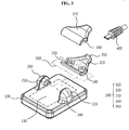
- FIGS. 2 and 3 are a perspective view and a disassembled perspective view of the first embodiment configuration of the present invention.
- the intraoral X-ray detector includes a sensor unit 100, a hinge unit200, and a cable connecting unit 300.
- a sensor 110 for detecting X-rays irradiated from an X-ray irradiation apparatus is included, and a receiving surface of the sensor 110 faces toward a lower surface of the sensor unit 100.
- the sensor 110 may be a digital X-ray sensor and function of converting radiation signals into electric signals or image signals.
- the digital X-ray sensor may be an indirect conversion type which converts radiation into visible light and converts again the visible light into electric signals, or a direct conversion type which converts the radiation directly into the electric signals.
- the indirect conversion type may include a scintillator for converting radiation into visible light and a digital image sensor for detecting the visible light
- the direct conversion type has an assembled form of a photoconductive conversion unit for converting the radiation into the electric signals with use of semiconductor material and a signal processing unit for converting the electric signals into the image signals. And this enables to get high performance and high resolution because the radiations are converted directly into the electric signals.
- the hinge unit 200 may be formed with two hinges, i.e., a first hinge 210 and a second hinge 220, and the first hinge 210 and the second hinge 220 are positioned to face each other. It is enough to locate the first hinge 210 and the second hinge 220 so as to face each other, at any side of the sensor unit 100 except the lower surface. Namely, the position of the hinge unit 200 is not limited to the upper surface different from the drawing.
- a fixing pin (not illustrated) for fixing the rotation position of the cable connecting unit 300 may be included at the first hinge 210 or the second hinge 220. It is possible to enhance the convenience in use at various regions within the mouth by fixing the cable connecting unit 300 before the rotation or after the rotation in direction of arrow by use of the fixing pin.
- the rotation is possible by the hinge unit, it is possible to minimize the volume occupied by the cable because the structure enables the cable connecting unit 300 stick to the surface of the sensor unit 100.
- the patient can minimize the feeling of irritation.
- the cable connecting unit 300 is rotatably connected to the first hinge 210 and the second hinge 220 and is able to move in the direction of the arrow. Further, an internal cable 500 drawn from the sensor 110 is connected, through the first hinge 210 and/or the second hinge 220 and through the inside of the cable connecting unit 300, to a cable connecting terminal 350 provided at one side of the cable connecting unit 300. In consequence, it is possible to transmit the electrical signals detected by the sensor 110 to an external cable 400.
- FIG. 3 elements of intraoral X-ray detector in accordance with an embodiment of the present invention will be described in detail.
- the first hinge 210 and the second hinge 220 may be formed by protrusion on the upper surface of the sensor unit 100 to have a cross-sectional surface of an oval shape in a vertical direction.
- the shape of the hinge is not limited to the oval shape but it may be modified in various shapes including a square, a rectangular and so on.
- a first hinge shaft 230 is formed in a protrusion manner to have a circular cross-sectional shape in a vertical direction at one side of the first hinge 210.
- a second hinge shaft 240 is formed to have a corresponding shape to the first hinge shaft 230 at one side of the second hinge 220 which facing the one side of the first hinge 210.
- the shape of the hinge shafts is not limited to the circular cross-sectional shape, but it can be variously modified as like hexagonal or octagonal shape.
- a first hinge shaft 230 and a second hinge shaft 240 are separated each other for easy attachment and detachment with the cable connecting unit 300 to be described later.
- they are not limited to this, but the first hinge shaft 230 and the second hinge shaft 240 may be linked to have one hinge shaft.
- the cable connecting unit 300 may be formed with a first frame 310 and a second frame 320 separable so as to be combined in attachable and detachable form to the hinge unit 200.
- a first connecting part 330 and a second connecting part 340 are formed to face each other at one portion of a side surface of the cable connecting unit 300 where the first frame 310 and the second frame 320 are coupled, the first connecting part 330 is coupled to the first hinge shaft 230 and the second connecting part 340 is coupled to the second hinge shaft 240 so that the cable connecting unit 300 is combined in a attachable and detachable with the hinge unit 200.
- the first connecting part 330 and the second connecting part 340 are combined to wrap first hinge shaft 230 and the second hinge shaft 240 respectively.
- the first connecting part 330 and the second connecting part 330 may be respectively formed in a shape of a circle corresponding to a cross-sectional surface in a vertical direction of the first hinge shaft 230 and the second hinge shaft 240. Additionally, not limited to this, it can be changed according the cross-sectional shape of the first hinge shaft 230 and the second hinge shaft 240 in a vertical direction.
- the first hinge shaft 230 and the second hinge shaft 240 are respectively formed in the first hinge 210 and the second hinge, and the first connecting part 330 and the second connecting part 340 are respectively formed in the cable connecting unit 300 to have a hinge coupling each other.
- the first hinge shaft 230 and the second hinge shaft 240 are respectively formed in the cable connecting unit 300, and the first connecting part 330 and the second connecting part 340 are respectively formed on the fist hinge 210 and the second hinge 220 have a hinge coupling each other.
- the sensor unit 100 and the cable connecting unit 300 may have the hinge coupling by changing the position of the hinge shaft and the hinge pin in variety.
- a cable connecting terminal 350 to be physically and electrically connected to or separated from the external cable 400 is formed at the rear side of the cable connecting unit 300, and the electric connection is possible by inserting a connecting terminal of the external cable into the cable connecting terminal 350.
- the internal cable 500 drawn from the sensor 110 of the sensor unit 100 is coupled to the cable connecting terminal 350 in side of the cable connecting unit 300 through the first hinge 210 and/or the second hinge 220 of the sensor unit 100 and the first connecting unit 330 and/or the second connecting unit 340 of the cable connecting unit 300.
- the external cable 400 is electrically coupled to the sensor 110 of the sensor when the connecting terminal of the external cable 400 is inserted into the cable connecting terminal 350. By doing this, the electric signals detected by the sensor 100 can be delivered to the external table 400.
- the external cable 400 and the cable connecting terminal 350 are respectively formed of a micro USB cable and a micro USB connecting terminal, but not limited there to, and various modifications including USB cable may be adopted.
- the cable connecting unit and the external cable can be detachably combined through the cable connecting terminal, but not limited there to, and the cable connecting unit and the external cable can be modified in an integral form in consideration of usage environment.
- the internal cable 500 and the external cable 400 are connected by a jumper cable (not illustrated) inside the cable connecting unit 300, or it is possible to make the external and internal cables are electrically coupled when hinge coupling of the first hinge shaft 230 and/or the second hinge shaft 240 and the first connecting unit 330 and/or the second connecting unit 340 by forming a first contacting terminal (not illustrated) to which the internal cable 500 is connected is formed at the first hinge 230 and/or the second hinge 240.
- a jumper cable (not illustrated) inside the cable connecting unit 300, or it is possible to make the external and internal cables are electrically coupled when hinge coupling of the first hinge shaft 230 and/or the second hinge shaft 240 and the first connecting unit 330 and/or the second connecting unit 340 by forming a first contacting terminal (not illustrated) to which the internal cable 500 is connected is formed at the first hinge 230 and/or the second hinge 240.
- the electrical connection can be maintained in stable despite of the rotation of the cable connecting unit 300 about the sensor unit 100 if slip rings and brushes are used as the first contacting terminal (not illustrated) and the second contacting terminal (not illustrated)
- the sensor unit 100 may be formed in a rectangular shape so as to take images in a direction of the normal teeth array and installed horizontally on the sensor unit.
- the first and second hinges 210 and 220 and the first and second hinge shafts 230 and 240 are disposed in a minor axis direction of the sensor unit.
- this hinge structure can be varied depending on the use or orientation of the sensor.
- FIGS. 4 to 9 are related to several embodiments of modification of the structure of the hinge combination between the cable connecting units 302 to 307 and the sensor units 102 to 107.
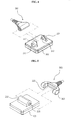
- FIG. 4 is a disassembled perspective view showing another modified embodiment of the invention in Fig.3
- the cable connecting unit 302 has the same configuration as the embodiment in Fig.3 , detailed description thereof will be omitted.
- a first hinge 212 and a second hinge 222 facing each other in the major axis direction are formed in the sensor unit 102, the first hinge shaft 232 is formed in the first hinge 212, and the second hinge shaft 242 is formed in the second hinge 222.
- FIG. 5 is a disassembled perspective view showing another modified embodiment of the invention in Fig.3 .
- the sensor unit 103 includes a hinge unit 213 which is formed protruding in the minor axis direction and a hinge shaft 223 formed at both side surfaces of the hinge unit, a cable connecting unit 303 is divided into two branches to have a rotary coupling part, which includes a first connecting part 313 to which the first hinge shaft 213 is inserted and the second connecting part 323 to which the second hinge shaft 213 is inserted are provided at inner side of the two divided ends. Accordingly, the cable connecting unit 303 is pivotally coupled and connected at both ends of the hinge unit213.
- FIG. 6 is an exploded perspective view showing the X-ray detector according to a fourth embodiment of the present invention.
- the sensor unit 104 includes a hinge 214 protrude in the major axis direction and a hinge shaft 224 formed at both side surfaces of the hinge.
- the cable connecting unit 304 includes a first connection unit 314 and a second connecting unit 324. Accordingly, the cable connecting unit 304 is pivotally coupled and connected at both ends of the hinge 214.
- FIG. 7 is an exploded perspective view showing another modified embodiment of the invention in Fig.3 .
- the sensor unit 105 includes a hinge unit 215 having a sunken shape in the minor axis direction and a pair of hinge shafts 225 protruded toward inside at both side surfaces of the hinge.
- the cable connecting unit 305 includes a pair of connecting units 315 to which a pair of hinges 225 are inserted at both ends thereof. Accordingly, the cable connecting unit 305 is pivotally coupled and connected at the hinge 215 inside of the sensor 105.
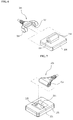
- FIG. 8 is an exploded perspective view showing another modified embodiment of the invention in Fig.3 .
- the sensor unit 106 includes a hinge unit 216 formed as a sunken shape in the major axis direction and a pair of hinge shafts 226 formed inwardly at both side surfaces of the hinge unit 216.
- the cable connecting unit 306 includes a pair of connecting units 326. Accordingly, the cable connecting unit 306 is pivotally coupled at the hinge 216 inside of the sensor 106.
- FIG. 9 is a view showing another modified embodiment of the invention in Fig.3 .
- the sensor unit 107 includes a pair of hinge units 217 facing each other in a direction sloped by a predetermined angel about the major and the minor axes direction and protruded from the sensor unit 107 and a pair of hinge shafts formed on the hinge, and a cable connecting unit 307 includes a pair of connecting units 317 at both ends there of the hinge shafts 227 are inserted. In this case, it has advantage of minimizing the size of the cable connecting unit 307 because it is possible to form the hinges 217 at the corners of the sensor unit 107.
- the sunken shape or the protrusion of the hinges is applicable with a modification, and all the structures with which the hinge shaft and the connecting unit are to be pivotally coupled each other are within the present invention.
- a rotational axis is formed on the cable connecting unit, and a connecting part of concave type may be formed on the hinge.
- the hinge and the connecting part may be substitute with hinges coupling each other and rotational connecting part corresponding thereto.
- FIGS. 10 and 11 are a perspective view and an exploded perspective view of a second embodiment configuration of the present invention.
- the intraoral X-ray detector includes a sensor unit 1100, a cable connecting unit 1200, and an external cable 1230.
- the sensor 1110 is equipped with in the sensor unit 1100, and a pair of connecting terminals 1120 in the sensor unit which is electrically connected with the sensor are exposed at both sides of the sensor unit.
- a part of the sensor unit is illustrated in cutting view in order to show the sensor and sensor unit connecting terminal 120 therein.
- the rotary coupling part 200 is branched in "U" shape so that both end parts are pivotally and electrically connected to the connecting terminal 120.
- a cable connecting unit 1200 includes an upper housing 1210 and a lower housing 1220, and further includes a connecting groove 1222 formed with one of these or combination thereof.
- a terminal connecting electrode 1240 which is made of the conductive material for delivering the power source and/or the signal is inserted.
- the electrode is formed in the u-shaped and is connected to the connecting terminal 1120 in both ends of a rotary coupling part of the sensor unit 100, and is connected to the external cable 1230.
- the terminal connecting electrode 1240 is formed in a divided two parts for an easy assemble, and each segment is connected to the one of the terminal connecting electrode, and they are respectively connected to the external cable 1230.
- the external cable 1230 is inserted and coupled together when the upper and lower housings 1210 and 1220 are assembled. And the cable accessing part 1232 which is an end part of the external cable 1230 is connected to the joint part 1244 of the terminal connecting electrode 1240. At this time, if necessary, the cable connecting unit 1230 may be connected to the terminal connecting electrode 1240 through the joint part 1244 by inserting the cable accessing part 1232 of the external cable 1230 at a side of an assembled body of the lower and the upper housings 1210 and 1220.
- a first connecting hole 1242 is formed, and a second connecting hole 1226 is also formed in the corresponding position in the end of the lower housing 1220.
- the connecting terminal 1120 as a hinge shaft is rotatably and electrically connected to the terminal connecting electrode 1240 through the second connecting hole 1226 by being inserted into the first connecting hole 1242. Therefore, the sensor 1110 within the mouth is electrically connected to the cable connecting unit 1230 connected to the outside.
- a protruded stopper 1228 is formed at one side of the cable connecting unit 1200, and the seating groove 1102 contacting with the stopper when the sensor unit 100 rotated with 180°C is formed in the sensor unit1100.
- a third connecting hole 1224 is formed when the upper and lower housings 1210 and 1220 of the cable connecting unit 1200 are assemble, and it is sealed up with the insulator 1250. Through this, it can be easily assembled, and the liquid within the mouth is electrically separated from the internal terminal 1120 and the terminal connecting electrode 1240.
- a electrical power is supplied through the cable connecting unit 1230, terminal connecting electrode 1240, and connecting terminal 1120 since the connecting terminal 1120 and the first connecting hole 1242 of the terminal connecting electrode 1240 rotate relatively, and it is possible to configure so that the sensing signal of the sensor unit 1100 can be transmitted and received wirelessly through the communication unit which is not illustrated and mounted within the sensor unit 1100.
- the electrical power is supplied through the external cable 1230 and the terminal connecting electrode 1240, and it is possible to deliver the electric signals generated by the intraoral X-ray imaging in the sensor 1110 of the sensor unit 1100 to the outside through the connecting terminal 1120, the terminal connecting electrode and the external cable 1230.
- FIG. 12 shows the section structure of the modified connecting terminal 1120 and the first connecting hole 1242 of the terminal connecting electrode 1240 in the oral X-ray detector according to the present invention.
- the connecting terminal 1120 has three electrodes 1122a, 1122b, 1122c composed of the concentric circle, and each electrode is formed to be stepped and is exposed to the outside and insulated each other.
- the first connecting hole 1242 of the terminal connecting electrode is formed to be stepped and has three internally exposed electrodes 1246a, 1246b, 1246c which are electrically insulated in each other. It is desirable that the remaining part of the electrode for the terminal connection is made of the insulating material since the three electrodes should be electrically isolated.
- the terminal connection electrode 1240 may have the form of PCB having multiple conductive lines on an insulator. If the connecting terminal 1120 is inserted into the first connecting hole 1242, only the electrodes of corresponding electrodes are contact to each other, in that way, electrodes of the respective connecting terminal 1120 are independently connected to the corresponding electrodes of the electrode 240 for the terminal connection.
- Exposed parts 1242a, 1242b, 1242c inside of the first connecting hole 1242 of each of the terminal connecting electrode 1240 are made of the ring or the brush form, and the contact with the electrodes of the connecting terminal 1120 are authentically maintained although the connecting terminal 1120 rotates.
- the exposed part is conductive and has bearing form so that it can facilitate the rotation easily.
- the connecting terminal 1120 and the first connecting hole 1242 of the terminal connecting electrode 1240 can be electrically connected in a multiple slip ring structure including multiple slipping electrodes insulated each other instead of a correspondingly stepped form at connecting terminal 1120, multiple brush electrodes faced and contacted in one-to-one to the multiple slipping electrodes at the first connecting hole 1242 of the terminal connecting electrode 1240.
- the three electrodes are used for power, signal transmission and signal reception.
- the number of electrode can be changed according to the driving method of the oral device for taking x-ray photographs, the imaging mechanism or software used.
- the sensor unit 1100 rotates at the angle in which the patient minimally can do the feeling of irritation of cable during the oral X-ray imaging because the cable connecting unit 1200 can rotate and the inconvenience of the patient can be minimized.
- the cable connecting unit 1200 rotates about the sensor unit 1100. And yet the circuit line in which the electrical connection can be authentically maintained is formed. Therefore, the transmission and/or reception including the power source or the image signal etc. can be guaranteed.
Landscapes
- Health & Medical Sciences (AREA)
- Life Sciences & Earth Sciences (AREA)
- Engineering & Computer Science (AREA)
- Medical Informatics (AREA)
- Physics & Mathematics (AREA)
- Biomedical Technology (AREA)
- General Health & Medical Sciences (AREA)
- Molecular Biology (AREA)
- High Energy & Nuclear Physics (AREA)
- Nuclear Medicine, Radiotherapy & Molecular Imaging (AREA)
- Optics & Photonics (AREA)
- Biophysics (AREA)
- Public Health (AREA)
- Pathology (AREA)
- Heart & Thoracic Surgery (AREA)
- Veterinary Medicine (AREA)
- Surgery (AREA)
- Animal Behavior & Ethology (AREA)
- Radiology & Medical Imaging (AREA)
- Dentistry (AREA)
- Oral & Maxillofacial Surgery (AREA)
- General Physics & Mathematics (AREA)
- Spectroscopy & Molecular Physics (AREA)
- Apparatus For Radiation Diagnosis (AREA)
- Measurement Of Radiation (AREA)
Abstract
Description
- This invention relates to an intraoral X-ray detectors and to an intraoral X-ray detector which is freely movable and easily repairable because a cable connecting unit, to which an external cable is attached, is hinge-coupled to be rotatable, to be attachable and detachable to the sensor part.
- In dentistry, generally, intraoral dental information is required to determine the conditions for the treatment of teeth, X-ray imaging device using the X-rays to obtain an intraoral dental information is provided.
- The X-ray imaging device is comprised of an X-ray irradiator and the X-ray detector for detecting the irradiated X-rays, usually the X-ray irradiated from an outside of a mouth are detected by the X-ray detector inside the mouth.
- As shown in
FIG. 1 , the conventional intraoral X-ray detector has a structure that acable connecting unit 20 to which theexternal cable 30 is attached and asensor unit 10 for detecting X-rays are formed integrally. - This conventional intraoral X-ray detector is not free to move the cable in the mouth, so there were drawbacks that an user should fold the cable to detect a particular tooth, or dispose the entire product even when the external cable connector are only damaged because the cable connecting unit and the sensor unit are formed in one body.
- Furthermore, it should be done in the shortest path to retract the
cable 30 from the mouth so that it can reduce the feeling of irritation of a patient. But as the conventional cable is fixed type, it can be different a folding degree of the cable or a retracting path of the cable as a position of teeth or a direction of biting. With these matters, the patient can be uncomfortable while obtaining images. - To solve the prior technical problem, this invention provides an intraoral X-ray detector which a sensor unit can be freely movable by a hinged connection between the sensor unit and a cable connecting unit which is connected to an external cable, and an external cable or a cable connecting unit can be easily replaceable when defects or damages are found in the external cable or the cable connecting unit.
- To achieve the object, the invention provides intraoral X-ray detector, including: a sensor unit having a built-in sensor for sensing X-rays; a hinge unit formed on one side of the sensor unit; a cable connecting unit being connected with an external cable and including a rotary coupling part rotatably coupling the cable connecting unit to the hinge unit, wherein an internal cable drawn from the sensor unit is electrically coupled to the external cable through the hinge unit, the rotary coupling part and inside of the cable connecting unit.
- The cable connecting unit is coupled to the hinge in a detachable manner through the rotary coupling part, and the cable connecting unit further includes a cable connecting terminal configured to be connected to the external cable and separated from the external cable, electrically and physically.
- The hinge unit may include a pair of hinges protruded facing each other in direction of a minor axis or the major axis direction on one side of the sensor unit, and a pair of hinge shafts protruded in a direction of facing each other from the pair of hinges, and the rotary coupling part includes a pair of connecting parts at both sides thereof, into which the pair of hinge shafts are respectively inserted.
- The hinge unit may include a sunken shaped in a direction of a major axis or a minor axis on one side of the sensing unit and a pair of hinge shafts formed at both sides of the hinge unit, and the rotary coupling part includes a pair of connecting parts, at both sides thereof, into which the pair of the hinge shafts are respectively inserted.
- The hinge unit may include a hinge formed in a sunken shape at one side of the sensor unit in the minor axis or the minor axis direction, and a pair of hinge shafts form at both sides of the hinge unit, and the rotary coupling part includes a pair of connecting parts, where the hinge shafts are respectively inserted, at both ends of the cable connecting unit.
- The hinge unit is formed to be sloped in a major axis direction of the sensor unit, and the rotary coupling part rotatably couples the cable connecting unit to the hinge unit.
- The hinge is formed on a corner at one side of the sensor unit. On the other hand, the hinge unit includes a pair of hinges facing each other and formed to be protruded from the sensor unit and a pair of hinge shafts formed on the hinges, and the rotary coupling unit includes a pair of connecting parts where the hinge shafts are inserted at both ends of the cable connecting unit.
- Otherwise, the hinge unit may be connecting terminals which is connected to the sensor and is protruded from the both side of the sensor unit. The rotary coupling part has two ends which are rotatably assembled to the connecting terminal. And a terminal connecting electrode can be contained in the cable connecting unit. The terminal connecting electrode electrically connects the connecting terminal and the external cable.
- Then, a first connecting hole and a second connecting hole are formed at both sides of the rotary coupling part to be connected to the connecting terminal. The connecting terminal is inserted through the first connecting hole and the second connecting hole and rotatably and electrically connected to the terminal connecting electrode.
- Desirably, a stopper formed on one side of the cable connecting unit and configured to limit the rotating angle of the sensing unit.
- According to the present invention, the cable connecting unit being connected to the external cable can be rotatably attached to the sensor unit by the hinge unit for the sensor unit to be easily moved in a mouth and then the user convenience can be increased.
- In addition, the cable connecting unit is detachably mounted on the hinge unit. The cable connecting unit further includes a cable connecting terminal which is electrically and physically connected to or separated with an external cable. Thus each component of the intraoral X-ray detector can be respectively replaced when there is a failure, and it is possible to have an effect of improving the economical efficiency and increasing of lifetime.
- In addition, even if the rotary coupling part rotates, the electrical connection can be ensured. So it is possible to improve the reliability of performance.
-
-
FIG. 1 is a prospective view schematically showing a conventional X-ray detector. -
FIG. 2 is a perspective view showing the intraoral X-ray detector according to the first embodiment of the present invention. -
FIG. 3 shows a perspective view of the disassembled intraoral X-ray detector inFIG. 2 . -
FIGS. 4 to 9 are views showing components of intraoral X-ray detector according to various modifications of the first embodiment of the present invention. -
FIG. 10 is a perspective view showing the disassembled intraoral X-ray detector according to the second embodiment of the present invention. -
FIG. 11 shows a perspective view of the assembled intraoral X-ray detector inFIG. 2 . -
FIG. 12 is a sectional view showing a connecting structure of the connecting terminal and the terminal connecting electrode of the X-ray detector inFIG. 10 . -
- 100: Sensor unit 310: First frame
- 110: Sensor 320: Second frame
- 200: Hinge 330: First connecting part
- 210: First hinge 340: Second connecting part
- 220: Second hinge 350: Cable connecting terminal
- 230:
First hinge shaft 400, 1230: External cable - 240: Second hinge shaft 500: Internal cable
- 300, 1200: Cable connecting unit 1120: Connecting terminal
- 1210: Upper housing 1220: Lower housing
- 1222: Connecting groove 1224: Second connecting hole
- 1226: Second connecting hole 1232: Cable accessing part
- 1240: Terminal connecting electrode 1242: First connecting hole
- 1122a, 1122b, 1122c: Terminal electrode
- 1242a, 1242b, 1242c: Exposed electrode part
- 1246a, 1246b, 1246c: Electrode
- Hereinafter be described with reference to the accompanying drawings, preferred embodiments of the present invention. Embodiment of the present invention may be modified in various other forms of, but is not limited to the scope of the invention embodiment to be described below. Shape, size, etc. of the elements in the FIG.s may be exaggerated for more clear explanation, the elements represented by the same reference numerals on the drawings are the same element.
- And in full herein, also it includes a case when some portion to said another portion and a "connection" which is not only the case, "directly connected to" another element in between "electrical connection" is that. In addition, when a part that is to some components "include" or "comprising", which means that not to exclude other components do not have a special substrate that is opposite to the other components may include or have the more.
- In this embodiment, the "major axis" direction of the sensor unit denotes the direction toward the longer side of the sensor unit, and the "minor axis" direction of the sensor unit denotes the direction toward the shorter side of the sensor unit.
-
FIGS. 2 and3 are a perspective view and a disassembled perspective view of the first embodiment configuration of the present invention. - Referring to
FIG. 2 , the intraoral X-ray detector, according to an embodiment of the present invention, includes asensor unit 100, a hinge unit200, and acable connecting unit 300. - In the
sensor unit 100, asensor 110 for detecting X-rays irradiated from an X-ray irradiation apparatus (not illustrated) is included, and a receiving surface of thesensor 110 faces toward a lower surface of thesensor unit 100. Thesensor 110 may be a digital X-ray sensor and function of converting radiation signals into electric signals or image signals. - The digital X-ray sensor may be an indirect conversion type which converts radiation into visible light and converts again the visible light into electric signals, or a direct conversion type which converts the radiation directly into the electric signals.
- The indirect conversion type may include a scintillator for converting radiation into visible light and a digital image sensor for detecting the visible light
- The direct conversion type has an assembled form of a photoconductive conversion unit for converting the radiation into the electric signals with use of semiconductor material and a signal processing unit for converting the electric signals into the image signals. And this enables to get high performance and high resolution because the radiations are converted directly into the electric signals.
- The
hinge unit 200 may be formed with two hinges, i.e., afirst hinge 210 and asecond hinge 220, and thefirst hinge 210 and thesecond hinge 220 are positioned to face each other. It is enough to locate thefirst hinge 210 and thesecond hinge 220 so as to face each other, at any side of thesensor unit 100 except the lower surface. Namely, the position of thehinge unit 200 is not limited to the upper surface different from the drawing. - A fixing pin (not illustrated) for fixing the rotation position of the
cable connecting unit 300 may be included at thefirst hinge 210 or thesecond hinge 220. It is possible to enhance the convenience in use at various regions within the mouth by fixing thecable connecting unit 300 before the rotation or after the rotation in direction of arrow by use of the fixing pin. - That is, the rotation is possible by the hinge unit, it is possible to minimize the volume occupied by the cable because the structure enables the
cable connecting unit 300 stick to the surface of thesensor unit 100. Thus, the patient can minimize the feeling of irritation. - The
cable connecting unit 300 is rotatably connected to thefirst hinge 210 and thesecond hinge 220 and is able to move in the direction of the arrow. Further, aninternal cable 500 drawn from thesensor 110 is connected, through thefirst hinge 210 and/or thesecond hinge 220 and through the inside of thecable connecting unit 300, to acable connecting terminal 350 provided at one side of thecable connecting unit 300. In consequence, it is possible to transmit the electrical signals detected by thesensor 110 to anexternal cable 400. - Referring to
FIG. 3 , elements of intraoral X-ray detector in accordance with an embodiment of the present invention will be described in detail. - The
first hinge 210 and thesecond hinge 220, for an example, may be formed by protrusion on the upper surface of thesensor unit 100 to have a cross-sectional surface of an oval shape in a vertical direction. The shape of the hinge is not limited to the oval shape but it may be modified in various shapes including a square, a rectangular and so on. - A
first hinge shaft 230 is formed in a protrusion manner to have a circular cross-sectional shape in a vertical direction at one side of thefirst hinge 210. Asecond hinge shaft 240 is formed to have a corresponding shape to thefirst hinge shaft 230 at one side of thesecond hinge 220 which facing the one side of thefirst hinge 210. Only, the shape of the hinge shafts is not limited to the circular cross-sectional shape, but it can be variously modified as like hexagonal or octagonal shape. - According to one embodiment of the invention, a
first hinge shaft 230 and asecond hinge shaft 240 are separated each other for easy attachment and detachment with thecable connecting unit 300 to be described later. However, they are not limited to this, but thefirst hinge shaft 230 and thesecond hinge shaft 240 may be linked to have one hinge shaft. - The
cable connecting unit 300 may be formed with afirst frame 310 and asecond frame 320 separable so as to be combined in attachable and detachable form to thehinge unit 200. In specific, a first connectingpart 330 and a second connectingpart 340 are formed to face each other at one portion of a side surface of thecable connecting unit 300 where thefirst frame 310 and thesecond frame 320 are coupled, the first connectingpart 330 is coupled to thefirst hinge shaft 230 and the second connectingpart 340 is coupled to thesecond hinge shaft 240 so that thecable connecting unit 300 is combined in a attachable and detachable with thehinge unit 200. - The first connecting
part 330 and the second connectingpart 340 are combined to wrapfirst hinge shaft 230 and thesecond hinge shaft 240 respectively. For this, the first connectingpart 330 and the second connectingpart 330 may be respectively formed in a shape of a circle corresponding to a cross-sectional surface in a vertical direction of thefirst hinge shaft 230 and thesecond hinge shaft 240. Additionally, not limited to this, it can be changed according the cross-sectional shape of thefirst hinge shaft 230 and thesecond hinge shaft 240 in a vertical direction. - In the embodiment of the present invention, the
first hinge shaft 230 and thesecond hinge shaft 240 are respectively formed in thefirst hinge 210 and the second hinge, and the first connectingpart 330 and the second connectingpart 340 are respectively formed in thecable connecting unit 300 to have a hinge coupling each other. However, on the contrary, it is also possible that thefirst hinge shaft 230 and thesecond hinge shaft 240 are respectively formed in thecable connecting unit 300, and the first connectingpart 330 and the second connectingpart 340 are respectively formed on thefist hinge 210 and thesecond hinge 220 have a hinge coupling each other. Besides, thesensor unit 100 and thecable connecting unit 300 may have the hinge coupling by changing the position of the hinge shaft and the hinge pin in variety. - A
cable connecting terminal 350 to be physically and electrically connected to or separated from theexternal cable 400 is formed at the rear side of thecable connecting unit 300, and the electric connection is possible by inserting a connecting terminal of the external cable into thecable connecting terminal 350. Theinternal cable 500 drawn from thesensor 110 of thesensor unit 100 is coupled to thecable connecting terminal 350 in side of thecable connecting unit 300 through thefirst hinge 210 and/or thesecond hinge 220 of thesensor unit 100 and the first connectingunit 330 and/or the second connectingunit 340 of thecable connecting unit 300. Thus, theexternal cable 400 is electrically coupled to thesensor 110 of the sensor when the connecting terminal of theexternal cable 400 is inserted into thecable connecting terminal 350. By doing this, the electric signals detected by thesensor 100 can be delivered to the external table 400. - In the embodiment of the present invention, the
external cable 400 and thecable connecting terminal 350 are respectively formed of a micro USB cable and a micro USB connecting terminal, but not limited there to, and various modifications including USB cable may be adopted. - In the embodiment of the present invention, the cable connecting unit and the external cable can be detachably combined through the cable connecting terminal, but not limited there to, and the cable connecting unit and the external cable can be modified in an integral form in consideration of usage environment.
- Desirably, the
internal cable 500 and theexternal cable 400 are connected by a jumper cable (not illustrated) inside thecable connecting unit 300, or it is possible to make the external and internal cables are electrically coupled when hinge coupling of thefirst hinge shaft 230 and/or thesecond hinge shaft 240 and the first connectingunit 330 and/or the second connectingunit 340 by forming a first contacting terminal (not illustrated) to which theinternal cable 500 is connected is formed at thefirst hinge 230 and/or thesecond hinge 240. - In particular, in case of the latter, the electrical connection can be maintained in stable despite of the rotation of the
cable connecting unit 300 about thesensor unit 100 if slip rings and brushes are used as the first contacting terminal (not illustrated) and the second contacting terminal (not illustrated) - The
sensor unit 100 may be formed in a rectangular shape so as to take images in a direction of the normal teeth array and installed horizontally on the sensor unit. In the above embodiment, the first andsecond hinges second hinge shafts -
FIGS. 4 to 9 are related to several embodiments of modification of the structure of the hinge combination between thecable connecting units 302 to 307 and thesensor units 102 to 107. -
FIG. 4 is a disassembled perspective view showing another modified embodiment of the invention inFig.3 - In this embodiment, since the
cable connecting unit 302 has the same configuration as the embodiment inFig.3 , detailed description thereof will be omitted. In thesensor unit 102, afirst hinge 212 and asecond hinge 222 facing each other in the major axis direction are formed in thesensor unit 102, thefirst hinge shaft 232 is formed in thefirst hinge 212, and thesecond hinge shaft 242 is formed in thesecond hinge 222. In this case, it is useful to minimize the feeling of irritation due to the cable when imaging is performed in the longitudinal direction to cover the root of the particular tooth by use of thesensor unit 210. -
FIG. 5 is a disassembled perspective view showing another modified embodiment of the invention inFig.3 . - In this embodiment in
Fig. 5 , thesensor unit 103 includes ahinge unit 213 which is formed protruding in the minor axis direction and ahinge shaft 223 formed at both side surfaces of the hinge unit, acable connecting unit 303 is divided into two branches to have a rotary coupling part, which includes a first connectingpart 313 to which thefirst hinge shaft 213 is inserted and the second connectingpart 323 to which thesecond hinge shaft 213 is inserted are provided at inner side of the two divided ends. Accordingly, thecable connecting unit 303 is pivotally coupled and connected at both ends of the hinge unit213. -
FIG. 6 is an exploded perspective view showing the X-ray detector according to a fourth embodiment of the present invention. - In this embodiment, the
sensor unit 104 includes ahinge 214 protrude in the major axis direction and ahinge shaft 224 formed at both side surfaces of the hinge. Like as the third embodiment, thecable connecting unit 304 includes afirst connection unit 314 and a second connectingunit 324. Accordingly, thecable connecting unit 304 is pivotally coupled and connected at both ends of thehinge 214. -
FIG. 7 is an exploded perspective view showing another modified embodiment of the invention inFig.3 . - In this embodiment in
Fig. 7 , thesensor unit 105 includes ahinge unit 215 having a sunken shape in the minor axis direction and a pair ofhinge shafts 225 protruded toward inside at both side surfaces of the hinge. Like as the first and the second embodiments, thecable connecting unit 305 includes a pair of connectingunits 315 to which a pair ofhinges 225 are inserted at both ends thereof. Accordingly, thecable connecting unit 305 is pivotally coupled and connected at thehinge 215 inside of thesensor 105. -
FIG. 8 is an exploded perspective view showing another modified embodiment of the invention inFig.3 . - This embodiment has modified a rotational direction of the embodiment, in
Fig. 7 , thesensor unit 106 includes ahinge unit 216 formed as a sunken shape in the major axis direction and a pair ofhinge shafts 226 formed inwardly at both side surfaces of thehinge unit 216. Like as the fifth embodiment, thecable connecting unit 306 includes a pair of connecting units 326. Accordingly, thecable connecting unit 306 is pivotally coupled at thehinge 216 inside of thesensor 106. -
FIG. 9 is a view showing another modified embodiment of the invention inFig.3 . - The
sensor unit 107 includes a pair ofhinge units 217 facing each other in a direction sloped by a predetermined angel about the major and the minor axes direction and protruded from thesensor unit 107 and a pair of hinge shafts formed on the hinge, and acable connecting unit 307 includes a pair of connectingunits 317 at both ends there of thehinge shafts 227 are inserted. In this case, it has advantage of minimizing the size of thecable connecting unit 307 because it is possible to form thehinges 217 at the corners of thesensor unit 107. - By the modification the embodiment in
Fig. 9 , it is possible to combine the cable connecting unit at both sides of the hinge or to form hinge units in a sunken shape. - In the embodiments in
Fig. 3 to Fig. 9 , the sunken shape or the protrusion of the hinges is applicable with a modification, and all the structures with which the hinge shaft and the connecting unit are to be pivotally coupled each other are within the present invention. For an instance, although it has not been described in the embodiments above, a rotational axis is formed on the cable connecting unit, and a connecting part of concave type may be formed on the hinge. In other words, the hinge and the connecting part may be substitute with hinges coupling each other and rotational connecting part corresponding thereto. -
FIGS. 10 and11 are a perspective view and an exploded perspective view of a second embodiment configuration of the present invention. - As shown in
FIG. 10 , the intraoral X-ray detector according to an embodiment of the present invention, includes asensor unit 1100, acable connecting unit 1200, and anexternal cable 1230. - The
sensor 1110 is equipped with in thesensor unit 1100, and a pair of connectingterminals 1120 in the sensor unit which is electrically connected with the sensor are exposed at both sides of the sensor unit. For reference, inFIG. 10 , a part of the sensor unit is illustrated in cutting view in order to show the sensor and sensor unit connecting terminal 120 therein. Therotary coupling part 200 is branched in "U" shape so that both end parts are pivotally and electrically connected to the connecting terminal 120. - A
cable connecting unit 1200 includes anupper housing 1210 and alower housing 1220, and further includes a connectinggroove 1222 formed with one of these or combination thereof. In the connecting groove, aterminal connecting electrode 1240 which is made of the conductive material for delivering the power source and/or the signal is inserted. The electrode is formed in the u-shaped and is connected to the connecting terminal 1120 in both ends of a rotary coupling part of thesensor unit 100, and is connected to theexternal cable 1230. In the present preferred embodiment, it is classified with the two for the convenience of assembly, theterminal connecting electrode 1240 is formed in a divided two parts for an easy assemble, and each segment is connected to the one of the terminal connecting electrode, and they are respectively connected to theexternal cable 1230. Theexternal cable 1230 is inserted and coupled together when the upper andlower housings cable accessing part 1232 which is an end part of theexternal cable 1230 is connected to thejoint part 1244 of theterminal connecting electrode 1240. At this time, if necessary, thecable connecting unit 1230 may be connected to theterminal connecting electrode 1240 through thejoint part 1244 by inserting thecable accessing part 1232 of theexternal cable 1230 at a side of an assembled body of the lower and theupper housings - At the end of the
electrode 1240, a first connectinghole 1242 is formed, and a second connectinghole 1226 is also formed in the corresponding position in the end of thelower housing 1220. The connecting terminal 1120 as a hinge shaft is rotatably and electrically connected to theterminal connecting electrode 1240 through the second connectinghole 1226 by being inserted into the first connectinghole 1242. Therefore, thesensor 1110 within the mouth is electrically connected to thecable connecting unit 1230 connected to the outside. - In order that the
sensor unit 100 sets up the initial position of the sensor, it is desirable not to rotate over 180°C. A protrudedstopper 1228 is formed at one side of thecable connecting unit 1200, and the seating groove 1102 contacting with the stopper when thesensor unit 100 rotated with 180°C is formed in the sensor unit1100. - As shown in
FIG. 11 , if thesensor unit 1100, thecable connecting unit 1200 andexternal cable 1230 are assembled, thesensor unit 1100 can be rotated according to the arrow, and it is limited by the stopper 228 in which the rotation range describes in the above with ± 180°C. In this preferred embodiment, a third connectinghole 1224 is formed when the upper andlower housings cable connecting unit 1200 are assemble, and it is sealed up with theinsulator 1250. Through this, it can be easily assembled, and the liquid within the mouth is electrically separated from theinternal terminal 1120 and theterminal connecting electrode 1240. - In this preferred, a electrical power is supplied through the
cable connecting unit 1230,terminal connecting electrode 1240, and connecting terminal 1120 since the connectingterminal 1120 and the first connectinghole 1242 of theterminal connecting electrode 1240 rotate relatively, and it is possible to configure so that the sensing signal of thesensor unit 1100 can be transmitted and received wirelessly through the communication unit which is not illustrated and mounted within thesensor unit 1100. On the other hand, the electrical power is supplied through theexternal cable 1230 and theterminal connecting electrode 1240, and it is possible to deliver the electric signals generated by the intraoral X-ray imaging in thesensor 1110 of thesensor unit 1100 to the outside through the connecting terminal 1120, the terminal connecting electrode and theexternal cable 1230. -
FIG. 12 shows the section structure of the modified connecting terminal 1120 and the first connectinghole 1242 of theterminal connecting electrode 1240 in the oral X-ray detector according to the present invention. As described inFIG. 12 , the connecting terminal 1120 has threeelectrodes hole 1242 of the terminal connecting electrode is formed to be stepped and has three internally exposedelectrodes terminal connection electrode 1240 with conductive material, it may have the form of PCB having multiple conductive lines on an insulator. If the connecting terminal 1120 is inserted into the first connectinghole 1242, only the electrodes of corresponding electrodes are contact to each other, in that way, electrodes of the respective connecting terminal 1120 are independently connected to the corresponding electrodes of theelectrode 240 for the terminal connection. -
Exposed parts hole 1242 of each of theterminal connecting electrode 1240 are made of the ring or the brush form, and the contact with the electrodes of the connecting terminal 1120 are authentically maintained although the connecting terminal 1120 rotates. Moreover, the exposed part is conductive and has bearing form so that it can facilitate the rotation easily. - Or on the other hand, the connecting
terminal 1120 and the first connectinghole 1242 of theterminal connecting electrode 1240 can be electrically connected in a multiple slip ring structure including multiple slipping electrodes insulated each other instead of a correspondingly stepped form at connecting terminal 1120, multiple brush electrodes faced and contacted in one-to-one to the multiple slipping electrodes at the first connectinghole 1242 of theterminal connecting electrode 1240. - In the above preferred embodiment, the three electrodes are used for power, signal transmission and signal reception. However, the number of electrode can be changed according to the driving method of the oral device for taking x-ray photographs, the imaging mechanism or software used.
- Consequently, according to the posture of the
sensor unit 1100, it rotates at the angle in which the patient minimally can do the feeling of irritation of cable during the oral X-ray imaging because thecable connecting unit 1200 can rotate and the inconvenience of the patient can be minimized. - Moreover, the
cable connecting unit 1200 rotates about thesensor unit 1100. And yet the circuit line in which the electrical connection can be authentically maintained is formed. Therefore, the transmission and/or reception including the power source or the image signal etc. can be guaranteed. - The invention described above is not limited to the above-described embodiments and drawings, It will be apparent to a person with a number of substituted, conventional knowledge in the art to which the invention pertains that variations and modifications are possible without departing from the scope of the technical concept of the present invention.
Claims (11)
- An intraoral X-ray detector comprising:a sensor unit having a sensor detecting X-rays;a hinge unit formed on the sensor unit; and,a cable connecting unit configured to be connected to an external cable and rotatably attached to the hinge unit.
- The intraoral X-ray detector of claim 1, wherein an internal cable drawn from the sensor unit is electrically connected to the external cable through the hinge unit and an inside of the cable connecting unit.
- The intraoral X-ray detector of claim 1, wherein the cable connecting unit is rotatably attached to the hinge unit.
- The intraoral X-ray detector of claim 1, wherein the cable connecting unit further includes a cable connecting terminal configured to be connected to the external cable and separated from the external cable, electrically and physically.
- The intraoral X-ray detector of claim 1, wherein the hinge unit further includes a pair of hinges protruded facing each other in a direction of a major axis or a minor axis on one side of the sensing unit and a pair of hinge shafts protruded in a direction of facing each other from the pair of hinges, and
the cable connecting unit includes a pair of connecting parts in which the pair of hinge shafts is inserted. - The intraoral X-ray detector of claim 1, wherein the hinge unit further includes a hinge protruded in a direction of a major axis or a minor axis on one side of the sensing unit and a pair of hinge shafts formed at both sides of the hinge unit, and
the cable connecting unit include a pair of connecting parts, at both sides thereof, into which the pair of hinge shafts are respectively inserted. - The intraoral X-ray detector of claim 1, wherein the hinge unit includes a sunken shaped hinge in a direction of a major axis or a minor axis on one side of the sensing unit and a pair of hinge shafts formed at both sides of the hinge unit, and
the cable connecting unit include a pair of connecting parts, at both sides thereof, into which the pair of hinge shafts are respectively inserted. - The intraoral X-ray detector of claim 1, wherein the hinge unit is formed to be sloped in a major axis direction of the sensor unit on one side of the sensor unit, and
the cable connecting unit is removably attached to the hinge unit. - The intraoral X-ray detector of claim 1, wherein the hinge unit is a connecting terminal connected to the sensor and being protruded in both direction of the sensor unit, both sides of the cable connecting unit are separately divided to be rotatably attached to the connecting terminal, and
the cable connecting unit further includes a terminal connecting electrode electrically connecting the connecting terminal and the external cable. - The intraoral X-ray detector of claim 9, wherein a first connecting hole and a second connecting hole are formed at both sides of the cable connecting unit to be connected to the connecting terminal, and
the connecting terminal is inserted through the first connecting hole and the second connecting hole and rotatably and electrically connected to the terminal connecting electrode. - The intraoral X-ray detector of claim 9, further comprising:a stopper formed on one side of the cable connecting unit and configured to limit the rotating angle of the sensing unit.
Applications Claiming Priority (4)
| Application Number | Priority Date | Filing Date | Title |
|---|---|---|---|
| KR20130165339 | 2013-12-27 | ||
| KR1020140169743A KR102368061B1 (en) | 2013-12-27 | 2014-12-01 | The intra-oral x-ray detecting device |
| KR1020140169744A KR102139365B1 (en) | 2013-12-27 | 2014-12-01 | The x-ray detecting device |
| PCT/KR2014/012903 WO2015099487A1 (en) | 2013-12-27 | 2014-12-26 | Device for detecting x-rays inside mouth |
Publications (3)
| Publication Number | Publication Date |
|---|---|
| EP3087924A1 true EP3087924A1 (en) | 2016-11-02 |
| EP3087924A4 EP3087924A4 (en) | 2017-10-18 |
| EP3087924B1 EP3087924B1 (en) | 2019-06-19 |
Family
ID=53790077
Family Applications (1)
| Application Number | Title | Priority Date | Filing Date |
|---|---|---|---|
| EP14875605.9A Active EP3087924B1 (en) | 2013-12-27 | 2014-12-26 | Device for detecting x-rays inside mouth |
Country Status (4)
| Country | Link |
|---|---|
| US (1) | US10165990B2 (en) |
| EP (1) | EP3087924B1 (en) |
| KR (2) | KR102368061B1 (en) |
| CN (1) | CN206463006U (en) |
Cited By (1)
| Publication number | Priority date | Publication date | Assignee | Title |
|---|---|---|---|---|
| FR3066817A1 (en) * | 2017-05-29 | 2018-11-30 | MCE 5 Development | MEASURING DEVICE FOR AN INTERNAL COMBUSTION ENGINE COMPRISING A TARGET PASSING DETECTOR AND MOTOR COMPRISING SUCH A MEASURING DEVICE |
Families Citing this family (8)
| Publication number | Priority date | Publication date | Assignee | Title |
|---|---|---|---|---|
| WO2018118956A1 (en) | 2016-12-20 | 2018-06-28 | 3M Innovative Properties Company | Composition including fluoropolymer and inorganic filler and method of making a three-dimensional article |
| KR101925425B1 (en) * | 2017-01-24 | 2019-02-27 | 주식회사 레이언스 | sensor holder for intraoral X-ray sensor |
| US11134903B2 (en) * | 2018-10-16 | 2021-10-05 | Shayda Cullen | Digital dental x-ray sensor device having a rounded housing |
| US11191497B2 (en) * | 2018-10-16 | 2021-12-07 | Shayda Cullen | Digital dental x-ray sensor device having a rounded housing including a radio transceiver |
| US10506992B1 (en) * | 2018-10-16 | 2019-12-17 | Shayda Cullen | Digital dental x-ray sensor device having a rounded housing |
| US11224387B2 (en) * | 2018-10-16 | 2022-01-18 | Shayda Cullen | Digital dental x-ray sensor device having a rounded housing |
| KR102085244B1 (en) * | 2019-03-08 | 2020-03-04 | 주식회사 나노레이 | Hand-grip type intra-oral X-ray sensor device |
| KR102241391B1 (en) * | 2019-04-08 | 2021-04-16 | 주식회사 나노레이 | Hand-grip type intra-oral X-ray sensor system having the function of horizontal aligning |
Family Cites Families (6)
| Publication number | Priority date | Publication date | Assignee | Title |
|---|---|---|---|---|
| KR19980017858U (en) * | 1996-09-24 | 1998-07-06 | 양재신 | Power plug |
| JPH10277028A (en) * | 1997-04-08 | 1998-10-20 | Morita Mfg Co Ltd | Dental x-ray image detector and adapter therefor |
| KR101020090B1 (en) * | 2008-06-02 | 2011-03-09 | 김청복 | Plug |
| JP2010162326A (en) | 2008-12-19 | 2010-07-29 | Panasonic Corp | Intraoral sensor and handle for intraoral sensor |
| CN202308475U (en) * | 2011-09-18 | 2012-07-04 | 徐杏杏 | Novel power plug |
| KR20130095498A (en) | 2012-02-20 | 2013-08-28 | (주)제노레이 | Intra oral sensor device and image making device using it |
-
2014
- 2014-12-01 KR KR1020140169743A patent/KR102368061B1/en active IP Right Grant
- 2014-12-01 KR KR1020140169744A patent/KR102139365B1/en active IP Right Grant
- 2014-12-26 EP EP14875605.9A patent/EP3087924B1/en active Active
- 2014-12-26 US US15/108,327 patent/US10165990B2/en active Active
- 2014-12-26 CN CN201490001358.XU patent/CN206463006U/en active Active
Cited By (4)
| Publication number | Priority date | Publication date | Assignee | Title |
|---|---|---|---|---|
| FR3066817A1 (en) * | 2017-05-29 | 2018-11-30 | MCE 5 Development | MEASURING DEVICE FOR AN INTERNAL COMBUSTION ENGINE COMPRISING A TARGET PASSING DETECTOR AND MOTOR COMPRISING SUCH A MEASURING DEVICE |
| WO2018220319A1 (en) * | 2017-05-29 | 2018-12-06 | MCE 5 Development | Engine comprising a measuring device for an internal combustion engine having a target passage detector |
| CN110914646A (en) * | 2017-05-29 | 2020-03-24 | Mce5发展公司 | Engine comprising a measuring device for an internal combustion engine with a target passage detector |
| CN110914646B (en) * | 2017-05-29 | 2022-05-13 | Mce5发展公司 | Engine comprising a measuring device for an internal combustion engine with a target passage detector |
Also Published As
| Publication number | Publication date |
|---|---|
| KR20150077299A (en) | 2015-07-07 |
| EP3087924B1 (en) | 2019-06-19 |
| KR102139365B1 (en) | 2020-07-29 |
| US10165990B2 (en) | 2019-01-01 |
| KR102368061B1 (en) | 2022-02-25 |
| CN206463006U (en) | 2017-09-05 |
| US20160324491A1 (en) | 2016-11-10 |
| EP3087924A4 (en) | 2017-10-18 |
| KR20150077298A (en) | 2015-07-07 |
Similar Documents
| Publication | Publication Date | Title |
|---|---|---|
| EP3087924B1 (en) | Device for detecting x-rays inside mouth | |
| JP2010162326A (en) | Intraoral sensor and handle for intraoral sensor | |
| JPH10277028A (en) | Dental x-ray image detector and adapter therefor | |
| JP2010262297A5 (en) | ||
| US20050220272A1 (en) | Wireless digital dental x-ray sensor with positioning apparatus | |
| KR101941840B1 (en) | Intraoral sensor and sensor indicator, and intraoral radiographic system including same | |
| CN115299863A (en) | Portable 3D tooth imager | |
| JP2013503708A (en) | Auxiliary parts for medical devices with additional functions | |
| CN208426093U (en) | Easy oral cavity detection device | |
| US20190378615A1 (en) | Wearable sensing device and sensor unit for acquiring one or more physiological signals of a subject | |
| CN105595949A (en) | Digestive tract detection system | |
| KR102085244B1 (en) | Hand-grip type intra-oral X-ray sensor device | |
| US20060274890A1 (en) | Image capture device and methods | |
| JP3650515B2 (en) | Digital sensor cassette for panoramic X-ray equipment | |
| FR2889658A1 (en) | DEVICE FOR RECEIVING MEDICAL SENSORS | |
| CN208837883U (en) | A kind of medical rotary motion endoscope apparatus | |
| JPH11104127A (en) | Panoramic radiography device | |
| JP2013096761A (en) | Radiation image photographing apparatus | |
| US9554758B2 (en) | Sensor integrated protection pad for shielding radiation | |
| JP2003079617A (en) | X-ray sensor unit, and x-ray imaging system using the same | |
| JP2013096760A (en) | Radiographic imaging apparatus | |
| CN217938175U (en) | Auxiliary device convenient to tooth disease is surveyd | |
| CN208404506U (en) | A kind of portable otoscope of ear type | |
| WO2015099487A1 (en) | Device for detecting x-rays inside mouth | |
| CN213722579U (en) | Electric toothbrush for taking pictures |
Legal Events
| Date | Code | Title | Description |
|---|---|---|---|
| PUAI | Public reference made under article 153(3) epc to a published international application that has entered the european phase |
Free format text: ORIGINAL CODE: 0009012 |
|
| 17P | Request for examination filed |
Effective date: 20160718 |
|
| AK | Designated contracting states |
Kind code of ref document: A1 Designated state(s): AL AT BE BG CH CY CZ DE DK EE ES FI FR GB GR HR HU IE IS IT LI LT LU LV MC MK MT NL NO PL PT RO RS SE SI SK SM TR |
|
| AX | Request for extension of the european patent |
Extension state: BA ME |
|
| DAX | Request for extension of the european patent (deleted) | ||
| A4 | Supplementary search report drawn up and despatched |
Effective date: 20170918 |
|
| RIC1 | Information provided on ipc code assigned before grant |
Ipc: A61B 6/00 20060101ALI20170912BHEP Ipc: G01T 1/161 20060101ALI20170912BHEP Ipc: A61B 6/14 20060101AFI20170912BHEP |
|
| GRAP | Despatch of communication of intention to grant a patent |
Free format text: ORIGINAL CODE: EPIDOSNIGR1 |
|
| STAA | Information on the status of an ep patent application or granted ep patent |
Free format text: STATUS: GRANT OF PATENT IS INTENDED |
|
| INTG | Intention to grant announced |
Effective date: 20180928 |
|
| GRAJ | Information related to disapproval of communication of intention to grant by the applicant or resumption of examination proceedings by the epo deleted |
Free format text: ORIGINAL CODE: EPIDOSDIGR1 |
|
| STAA | Information on the status of an ep patent application or granted ep patent |
Free format text: STATUS: REQUEST FOR EXAMINATION WAS MADE |
|
| GRAP | Despatch of communication of intention to grant a patent |
Free format text: ORIGINAL CODE: EPIDOSNIGR1 |
|
| STAA | Information on the status of an ep patent application or granted ep patent |
Free format text: STATUS: GRANT OF PATENT IS INTENDED |
|
| INTC | Intention to grant announced (deleted) | ||
| INTG | Intention to grant announced |
Effective date: 20190107 |
|
| GRAS | Grant fee paid |
Free format text: ORIGINAL CODE: EPIDOSNIGR3 |
|
| GRAA | (expected) grant |
Free format text: ORIGINAL CODE: 0009210 |
|
| STAA | Information on the status of an ep patent application or granted ep patent |
Free format text: STATUS: THE PATENT HAS BEEN GRANTED |
|
| AK | Designated contracting states |
Kind code of ref document: B1 Designated state(s): AL AT BE BG CH CY CZ DE DK EE ES FI FR GB GR HR HU IE IS IT LI LT LU LV MC MK MT NL NO PL PT RO RS SE SI SK SM TR |
|
| REG | Reference to a national code |
Ref country code: GB Ref legal event code: FG4D |
|
| REG | Reference to a national code |
Ref country code: CH Ref legal event code: EP |
|
| REG | Reference to a national code |
Ref country code: IE Ref legal event code: FG4D |
|
| REG | Reference to a national code |
Ref country code: AT Ref legal event code: REF Ref document number: 1144471 Country of ref document: AT Kind code of ref document: T Effective date: 20190715 |
|
| REG | Reference to a national code |
Ref country code: DE Ref legal event code: R096 Ref document number: 602014048864 Country of ref document: DE |
|
| REG | Reference to a national code |
Ref country code: NL Ref legal event code: MP Effective date: 20190619 |
|
| PG25 | Lapsed in a contracting state [announced via postgrant information from national office to epo] |
Ref country code: LT Free format text: LAPSE BECAUSE OF FAILURE TO SUBMIT A TRANSLATION OF THE DESCRIPTION OR TO PAY THE FEE WITHIN THE PRESCRIBED TIME-LIMIT Effective date: 20190619 Ref country code: HR Free format text: LAPSE BECAUSE OF FAILURE TO SUBMIT A TRANSLATION OF THE DESCRIPTION OR TO PAY THE FEE WITHIN THE PRESCRIBED TIME-LIMIT Effective date: 20190619 Ref country code: SE Free format text: LAPSE BECAUSE OF FAILURE TO SUBMIT A TRANSLATION OF THE DESCRIPTION OR TO PAY THE FEE WITHIN THE PRESCRIBED TIME-LIMIT Effective date: 20190619 Ref country code: NO Free format text: LAPSE BECAUSE OF FAILURE TO SUBMIT A TRANSLATION OF THE DESCRIPTION OR TO PAY THE FEE WITHIN THE PRESCRIBED TIME-LIMIT Effective date: 20190919 Ref country code: AL Free format text: LAPSE BECAUSE OF FAILURE TO SUBMIT A TRANSLATION OF THE DESCRIPTION OR TO PAY THE FEE WITHIN THE PRESCRIBED TIME-LIMIT Effective date: 20190619 |
|
| REG | Reference to a national code |
Ref country code: LT Ref legal event code: MG4D |
|
| PG25 | Lapsed in a contracting state [announced via postgrant information from national office to epo] |
Ref country code: BG Free format text: LAPSE BECAUSE OF FAILURE TO SUBMIT A TRANSLATION OF THE DESCRIPTION OR TO PAY THE FEE WITHIN THE PRESCRIBED TIME-LIMIT Effective date: 20190919 Ref country code: LV Free format text: LAPSE BECAUSE OF FAILURE TO SUBMIT A TRANSLATION OF THE DESCRIPTION OR TO PAY THE FEE WITHIN THE PRESCRIBED TIME-LIMIT Effective date: 20190619 Ref country code: RS Free format text: LAPSE BECAUSE OF FAILURE TO SUBMIT A TRANSLATION OF THE DESCRIPTION OR TO PAY THE FEE WITHIN THE PRESCRIBED TIME-LIMIT Effective date: 20190619 Ref country code: GR Free format text: LAPSE BECAUSE OF FAILURE TO SUBMIT A TRANSLATION OF THE DESCRIPTION OR TO PAY THE FEE WITHIN THE PRESCRIBED TIME-LIMIT Effective date: 20190920 |
|
| REG | Reference to a national code |
Ref country code: AT Ref legal event code: MK05 Ref document number: 1144471 Country of ref document: AT Kind code of ref document: T Effective date: 20190619 |
|
| PG25 | Lapsed in a contracting state [announced via postgrant information from national office to epo] |
Ref country code: SK Free format text: LAPSE BECAUSE OF FAILURE TO SUBMIT A TRANSLATION OF THE DESCRIPTION OR TO PAY THE FEE WITHIN THE PRESCRIBED TIME-LIMIT Effective date: 20190619 Ref country code: RO Free format text: LAPSE BECAUSE OF FAILURE TO SUBMIT A TRANSLATION OF THE DESCRIPTION OR TO PAY THE FEE WITHIN THE PRESCRIBED TIME-LIMIT Effective date: 20190619 Ref country code: NL Free format text: LAPSE BECAUSE OF FAILURE TO SUBMIT A TRANSLATION OF THE DESCRIPTION OR TO PAY THE FEE WITHIN THE PRESCRIBED TIME-LIMIT Effective date: 20190619 Ref country code: CZ Free format text: LAPSE BECAUSE OF FAILURE TO SUBMIT A TRANSLATION OF THE DESCRIPTION OR TO PAY THE FEE WITHIN THE PRESCRIBED TIME-LIMIT Effective date: 20190619 Ref country code: AT Free format text: LAPSE BECAUSE OF FAILURE TO SUBMIT A TRANSLATION OF THE DESCRIPTION OR TO PAY THE FEE WITHIN THE PRESCRIBED TIME-LIMIT Effective date: 20190619 Ref country code: EE Free format text: LAPSE BECAUSE OF FAILURE TO SUBMIT A TRANSLATION OF THE DESCRIPTION OR TO PAY THE FEE WITHIN THE PRESCRIBED TIME-LIMIT Effective date: 20190619 Ref country code: PT Free format text: LAPSE BECAUSE OF FAILURE TO SUBMIT A TRANSLATION OF THE DESCRIPTION OR TO PAY THE FEE WITHIN THE PRESCRIBED TIME-LIMIT Effective date: 20191021 |
|
| PG25 | Lapsed in a contracting state [announced via postgrant information from national office to epo] |
Ref country code: SM Free format text: LAPSE BECAUSE OF FAILURE TO SUBMIT A TRANSLATION OF THE DESCRIPTION OR TO PAY THE FEE WITHIN THE PRESCRIBED TIME-LIMIT Effective date: 20190619 Ref country code: IS Free format text: LAPSE BECAUSE OF FAILURE TO SUBMIT A TRANSLATION OF THE DESCRIPTION OR TO PAY THE FEE WITHIN THE PRESCRIBED TIME-LIMIT Effective date: 20191019 Ref country code: ES Free format text: LAPSE BECAUSE OF FAILURE TO SUBMIT A TRANSLATION OF THE DESCRIPTION OR TO PAY THE FEE WITHIN THE PRESCRIBED TIME-LIMIT Effective date: 20190619 |
|
| PG25 | Lapsed in a contracting state [announced via postgrant information from national office to epo] |
Ref country code: TR Free format text: LAPSE BECAUSE OF FAILURE TO SUBMIT A TRANSLATION OF THE DESCRIPTION OR TO PAY THE FEE WITHIN THE PRESCRIBED TIME-LIMIT Effective date: 20190619 |
|
| PG25 | Lapsed in a contracting state [announced via postgrant information from national office to epo] |
Ref country code: PL Free format text: LAPSE BECAUSE OF FAILURE TO SUBMIT A TRANSLATION OF THE DESCRIPTION OR TO PAY THE FEE WITHIN THE PRESCRIBED TIME-LIMIT Effective date: 20190619 Ref country code: DK Free format text: LAPSE BECAUSE OF FAILURE TO SUBMIT A TRANSLATION OF THE DESCRIPTION OR TO PAY THE FEE WITHIN THE PRESCRIBED TIME-LIMIT Effective date: 20190619 |
|
| PG25 | Lapsed in a contracting state [announced via postgrant information from national office to epo] |
Ref country code: IS Free format text: LAPSE BECAUSE OF FAILURE TO SUBMIT A TRANSLATION OF THE DESCRIPTION OR TO PAY THE FEE WITHIN THE PRESCRIBED TIME-LIMIT Effective date: 20200224 |
|
| REG | Reference to a national code |
Ref country code: DE Ref legal event code: R097 Ref document number: 602014048864 Country of ref document: DE |
|
| PLBE | No opposition filed within time limit |
Free format text: ORIGINAL CODE: 0009261 |
|
| STAA | Information on the status of an ep patent application or granted ep patent |
Free format text: STATUS: NO OPPOSITION FILED WITHIN TIME LIMIT |
|
| PG2D | Information on lapse in contracting state deleted |
Ref country code: IS |
|
| REG | Reference to a national code |
Ref country code: CH Ref legal event code: PL |
|
| 26N | No opposition filed |
Effective date: 20200603 |
|
| REG | Reference to a national code |
Ref country code: BE Ref legal event code: MM Effective date: 20191231 |
|
| PG25 | Lapsed in a contracting state [announced via postgrant information from national office to epo] |
Ref country code: SI Free format text: LAPSE BECAUSE OF FAILURE TO SUBMIT A TRANSLATION OF THE DESCRIPTION OR TO PAY THE FEE WITHIN THE PRESCRIBED TIME-LIMIT Effective date: 20190619 Ref country code: MC Free format text: LAPSE BECAUSE OF FAILURE TO SUBMIT A TRANSLATION OF THE DESCRIPTION OR TO PAY THE FEE WITHIN THE PRESCRIBED TIME-LIMIT Effective date: 20190619 |
|
| PG25 | Lapsed in a contracting state [announced via postgrant information from national office to epo] |
Ref country code: LU Free format text: LAPSE BECAUSE OF NON-PAYMENT OF DUE FEES Effective date: 20191226 Ref country code: IE Free format text: LAPSE BECAUSE OF NON-PAYMENT OF DUE FEES Effective date: 20191226 |
|
| PG25 | Lapsed in a contracting state [announced via postgrant information from national office to epo] |
Ref country code: CH Free format text: LAPSE BECAUSE OF NON-PAYMENT OF DUE FEES Effective date: 20191231 Ref country code: LI Free format text: LAPSE BECAUSE OF NON-PAYMENT OF DUE FEES Effective date: 20191231 Ref country code: BE Free format text: LAPSE BECAUSE OF NON-PAYMENT OF DUE FEES Effective date: 20191231 |
|
| PG25 | Lapsed in a contracting state [announced via postgrant information from national office to epo] |
Ref country code: CY Free format text: LAPSE BECAUSE OF FAILURE TO SUBMIT A TRANSLATION OF THE DESCRIPTION OR TO PAY THE FEE WITHIN THE PRESCRIBED TIME-LIMIT Effective date: 20190619 |
|
| PG25 | Lapsed in a contracting state [announced via postgrant information from national office to epo] |
Ref country code: MT Free format text: LAPSE BECAUSE OF FAILURE TO SUBMIT A TRANSLATION OF THE DESCRIPTION OR TO PAY THE FEE WITHIN THE PRESCRIBED TIME-LIMIT Effective date: 20190619 Ref country code: HU Free format text: LAPSE BECAUSE OF FAILURE TO SUBMIT A TRANSLATION OF THE DESCRIPTION OR TO PAY THE FEE WITHIN THE PRESCRIBED TIME-LIMIT; INVALID AB INITIO Effective date: 20141226 |
|
| PG25 | Lapsed in a contracting state [announced via postgrant information from national office to epo] |
Ref country code: MK Free format text: LAPSE BECAUSE OF FAILURE TO SUBMIT A TRANSLATION OF THE DESCRIPTION OR TO PAY THE FEE WITHIN THE PRESCRIBED TIME-LIMIT Effective date: 20190619 |
|
| P01 | Opt-out of the competence of the unified patent court (upc) registered |
Effective date: 20230525 |
|
| REG | Reference to a national code |
Ref country code: DE Ref legal event code: R079 Ref document number: 602014048864 Country of ref document: DE Free format text: PREVIOUS MAIN CLASS: A61B0006140000 Ipc: A61B0006510000 |
|
| PGFP | Annual fee paid to national office [announced via postgrant information from national office to epo] |
Ref country code: GB Payment date: 20231023 Year of fee payment: 10 |
|
| PGFP | Annual fee paid to national office [announced via postgrant information from national office to epo] |
Ref country code: IT Payment date: 20231025 Year of fee payment: 10 Ref country code: FR Payment date: 20231024 Year of fee payment: 10 Ref country code: FI Payment date: 20231023 Year of fee payment: 10 Ref country code: DE Payment date: 20231023 Year of fee payment: 10 |