EP3087875B1 - Produktverwaltungsanzeigesystem - Google Patents
Produktverwaltungsanzeigesystem Download PDFInfo
- Publication number
- EP3087875B1 EP3087875B1 EP16152092.9A EP16152092A EP3087875B1 EP 3087875 B1 EP3087875 B1 EP 3087875B1 EP 16152092 A EP16152092 A EP 16152092A EP 3087875 B1 EP3087875 B1 EP 3087875B1
- Authority
- EP
- European Patent Office
- Prior art keywords
- divider
- pusher
- product
- front rail
- barrier
- Prior art date
- Legal status (The legal status is an assumption and is not a legal conclusion. Google has not performed a legal analysis and makes no representation as to the accuracy of the status listed.)
- Active
Links
Images






















































Classifications
-
- A—HUMAN NECESSITIES
- A47—FURNITURE; DOMESTIC ARTICLES OR APPLIANCES; COFFEE MILLS; SPICE MILLS; SUCTION CLEANERS IN GENERAL
- A47F—SPECIAL FURNITURE, FITTINGS, OR ACCESSORIES FOR SHOPS, STOREHOUSES, BARS, RESTAURANTS OR THE LIKE; PAYING COUNTERS
- A47F1/00—Racks for dispensing merchandise; Containers for dispensing merchandise
- A47F1/04—Racks or containers with arrangements for dispensing articles, e.g. by means of gravity or springs
- A47F1/12—Racks or containers with arrangements for dispensing articles, e.g. by means of gravity or springs dispensing from the side of an approximately horizontal stack
- A47F1/125—Racks or containers with arrangements for dispensing articles, e.g. by means of gravity or springs dispensing from the side of an approximately horizontal stack with an article-pushing device
- A47F1/126—Racks or containers with arrangements for dispensing articles, e.g. by means of gravity or springs dispensing from the side of an approximately horizontal stack with an article-pushing device the pushing device being urged by spring means
Definitions
- Other systems include the use of a pusher system to push the product toward the front of the shelf as the product at the front of the shelf is removed.
- the known pusher systems are typically mounted to a track and include a pusher paddle and a coiled spring to urge the product forward.
- the track becomes obstructed with dirt or sticky materials that hinder the proper operation of the pusher system in the track.
- the known pusher paddles may occasionally tip or bend backwards, thereby causing a binding of the pusher mechanism in the track. In those situations, the pusher mechanism may not properly push product toward the front of the shelf.
- the pusher paddle may define a concave pushing surface for pushing cylindrical products, such as soft drink bottles or cans, and to keep the paddle centered on the track and behind the product.
- the pusher paddle may define a flat pushing surface that may further include at its upper edge a curved rib or similar structure that can also be used to push cylindrical products.
- the trays can be attached via a dovetail connection to form a shelf assembly. Additionally the dividers can be adjusted such that the width of the product rows can be adapted to receive different sized products.
- a product management display system for merchandising product on a shelf that includes using a trackless pusher mechanism that travels along a surface on which product is placed and one or more dividers for separating product into rows is disclosed.
- the one or more dividers may be attached and releasably engaged to a front rail. When the one or more dividers are not engaged and held in position to the front rail, the one or more dividers and product positioned on the display system may be moved in a lateral direction, or may be lifted away from the front rail. This permits ease of replanogramming of product on the shelf.
- the one or more dividers may releasably engage to the front rail through the use of corresponding teeth, resilient surfaces, a locking tab, a locking bar, a cam and/or through a friction or press fit.
- the at least one divider is (a) movable in a lateral direction parallel to the front rail and (b) secured in a direction perpendicular to the front rail when the at least one first projection of the front rail is engaged with the at least one recess of the divider and the at least one second projection of the front rail is in the first position.
- the at least one divider is (a) fixed in the lateral direction parallel to the front rail and (b) secured in the direction perpendicular to the front rail when the at least one first projection of the front rail is engaged with the at least one recess of the divider and the at least one second projection of the front rail is in the second position.
- the display system may include a pusher extender that increases the pushing surface of the pusher.
- the pusher extender may define an elongated pusher body having a cavity.
- the pusher extender may be configured to slide over the pusher wall via the cavity like a sleeve.
- the pusher extender with an enlarged, substantially planar surface thereby creates an enlarged pushing surface for pushing larger products toward the front of the display system.
- an adaptor 180 may be positioned on the surface 16.
- the adaptor 180 may include one or more raised ribs 182 on which a product may sit.
- the raised ribs 182 may extend longitudinally along the length of the adaptor 180.
- the adaptor 180 may be a flat extrusion of plastic material (or any other suitable material) defining a planar surface 184 with the one or more ribs 182 extending outwardly from the planar surface 184.
- the adaptor 180 may define a rounded end 185 and include a notch or cut-away portion 186 through which or across which the coiled spring may extend.
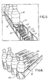
- the trackless pusher mechanism 14 is shown mounted to the tray 12. As illustrated, the pusher mechanism 14 fits in the tray 12 between the dividers 18. End 29 of the coiled spring 30 extends through the notch in the pusher floor and mounts to the tray as described above. In use, the pusher mechanism 14 will slide along the surface 16 of the tray 12 without the use of tracks, rails, or guides. As depicted in FIG. 2 , the pusher mechanism 14 is shown in a forward position.
- multiple trays 12 may be formed into a single multi-tray assembly 80.
- the multi-trays may have a common floor with dividers 18 extending upwardly from the floor to create the multiple trays or rows.
- the product-retaining member 44 may be a solid member that extends between two dividers, as discussed above.
- One or more of the multi-tray assemblies 80 may be coupled or joined together in a side-by-side manner using any known technique, including clips, dovetailing, fasteners, or the like. With this configuration, numerous rows of product can be provided for the merchandising of numerous products.
- the trackless pusher mechanism 14 may be used with gravity-fed systems, that is, systems having trays or product channels that are mounted on an incline to permit gravity to assist with the merchandising of the product.
- the trackless pusher mechanism 14 may be used with systems that are mounted in a non-inclined or in a horizontal manner where gravity will provide little or no assistance with the merchandising of the product.
- the trackless pusher mechanism 14 may also be used to push various shaped products.
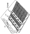
- the connecting portions 272 When assembled, as depicted in FIG. 41C , the connecting portions 272 are received between the teeth 278 of the rails. Additionally, the elongated angled surfaces 268 and 270 and the projections 274 are wedged between the teeth 278. Also as shown in FIG. 41C , the elongated angled surfaces 268 and 270 engage the face surfaces 280, and the projections 274 engage the lower surfaces of the teeth 278. Flank surfaces 282 contact the connecting portion 272.
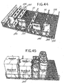
- the trays 306 are provided with dovetail connections.
- a first side 308 of the trays 306 is provided with tongues 312 adapted to fit within grooves 314 located on a second side 310 of the trays 306.
- the grooves 314 are aligned with tongues 312 such that the tongues 312 are firmly secured within the grooves 314.
- the barrier is not integral with or integrated with the divider. In another example, the barrier is configured to engage with the divider. In an example, the divider wall and the divider floor are separate devices from each other and are not integral with each other or part of a single integrated device. In an example, the divider wall and the divider floor are configured to engage with each other. In further examples, a barrier can be connected to the front rail 580 or comprise a portion of the front rail 580.
- the teeth 588 or other engaging member of the front rail 580 can be spaced apart.
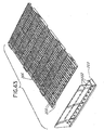
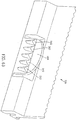
- the teeth 588 or other engaging member of the front rail can engage the teeth 562 or other engaging member of the divider 550, which teeth 562 are illustrated in FIG. 63 , so as to prevent the divider from moving in a lateral direction parallel to the front rail 580.
- the teeth 588 or other engaging member of the front rail 580 are engaged with the teeth 562 or other engaging member of the divider 550 and prevent the divider 550 from moving in the lateral direction shown by arrow "A" in FIG. 65 .
- the term engaging member as used herein can mean a projection, recess, planar surface, near-planar surface, or other item of structure that can engage with another item of structure.
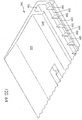
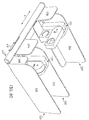
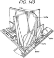
- a merchandise display system includes a front rail 580 and at least one divider 550 configured to attach to the front rail 580, the at least one divider 550 including a barrier, a divider wall 552 extending in a direction perpendicular to the front rail, a divider floor 554 perpendicular to the divider wall 552, wherein the divider wall 552 separates the divider floor 554 into a first portion and a second portion and each of the first portion and the second portion are configured to hold product.
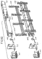
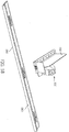
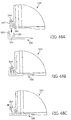
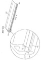
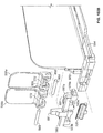
- FIGS. 83A-C show a step by step process for insertion of the divider 550 into the front rail 580.
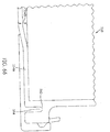
- the divider 550 is lowered into a channel 640 formed in the front rail 580.
- the front rail 580 includes a rotating rod 660 which itself includes teeth.
- the teeth of the rotating rod 660 are in a first position in which they are not engaged with the teeth 600 of the divider 550.
- the tongue 724 only has two cam walls.
- a first cam wall such as first cam wall 726
- a second cam wall is straight and spans the length shown by cam walls 728 and 730. There is no bend in the second cam wall in this example.
- the cam walls can extend for one or more portions of the width of the divider 550 or can extend the entire width of the divider 550.
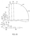
- the cam 720 fits within a cavity 740 of the barrier 556, as illustrated in FIG. 86G .
- the cavity 740 is bounded by side walls 742. Side walls 742 render the front of the cavity 740 slightly narrower than the width of cam 720. An amount of force is required to push cam 720 past side walls 742 and into cavity 740. After the cam passes the side walls 742 it snaps into place in the cavity 740. The cam 720 can then rotate in cavity 740 and will not fall out of cavity 740 or detach from cavity 740 during normal use.
- the cam 720 is rotatably secured within cavity 740.
- cavity 740 also is bounded at its front portion by a front wall (not shown).
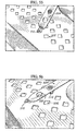
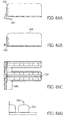
- the front wall 561 of groove 560 is textured, as shown in FIG. 86K .
- This texturing can be in the form of roughening or small teeth.
- the texturing causes the surface of the front wall 561 of groove 560 to not be smooth.
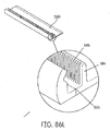
- front wall 585 of ridge 584 or other protrusion or engaging member is textured, as depicted in FIGS. 86I, 86J , and 86L .
- This texturing can be in the form of roughening or small teeth and causes the surface of front wall 585 of ridge 584 to not be smooth.
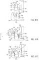
- front wall 561 of groove 560 is not in contact with or not in consistent contact with front wall 585 of ridge 584 while the cam 720 is in the position shown in FIG. 87B and the tongue of cam 720 is not engaged with groove 750 of front rail 580.
- the cam 720 is moved from a first position shown in FIG. 87B to a second position shown in FIG. 97C , and the tongue 724 engages with groove 750, the tongue can force the divider 550 to move backward.
- tension between the tongue 724 and the groove 750 forces divider 550 to move in a rearward direction.
- the divider 550 can be moved in a lateral direction parallel to the front rail and can allow for ease of replanogramming.
- the divider 550 can move along the front rail.
- the divider 550, with or without product on the divider floor 554, can be slid in the direction previously noted by arrow "A" in FIG. 65 , without requiring that the divider 550 be lifted up.
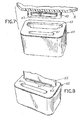
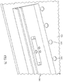
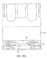
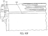
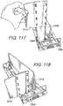
- the rotating "T" lock 900 may be pushed forward and downwardly toward the front rail 580.
- the rotating "T" lock 900 may engage with a lip 901 on a front portion of the front rail 580.
- the front rail 580 includes a top front surface 902.
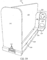
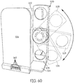
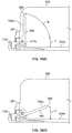
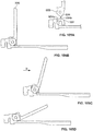
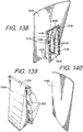
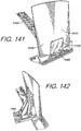
- a merchandise display system includes a barrier that is moveable by rotation between a folded position and an upright position without the aid of, for example, a rotation biasing element (such as a spring loaded hinge) dedicated to biasing the barrier into the upright position.
- a rotation biasing element such as a spring loaded hinge
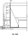
- FIGS. 95 through 106 Various example aspects of example systems that include a barrier that is moveable between a folded position and an upright position without the aid of a rotation biasing element are shown in FIGS. 95 through 106 .
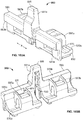
- the system includes a divider assembly 550 configured to be secured to a support structure.
- a divider assembly 550 can also be referred to as a divider 550.
- a support structure can include, for example, a front rail 580.
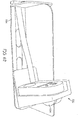
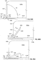
- a force applied in the forward direction to a product positioned in contact with at least a portion of the rear surface 569 of the barrier 556 while the barrier is in the folded position can cause the barrier to rotate from the folded position to the upright position.
- a product can be placed on the top surface 554a of the divider floor 554 while the barrier is in the folded position.
- a force can be applied to the product to move the product in the forward direction toward the barrier, as shown by example in FIG. 99B .
- the force is gravity.
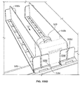
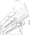
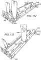
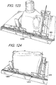
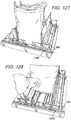
- the alignment flap 577 is configured to be positioned in between opposing divider walls of a merchandise display system such that the alignment flap aligns the product tray and the product stored in the product tray with the product pocket so that the product stored in the product tray can be slid from within the product tray, as shown in FIG. 101D , directly into the product pocket of the merchandise display system, as shown in FIG. 101E .
- a portion of the alignment flap can be tapered toward the distal end to aid in insertion of the alignment flap between the opposing divider walls of the system.
- the alignment flap can be used to move the barriers from the upright position to the folded position to facilitate sliding of the product from the product tray into the product pocket of the system.
- the unbiased barrier 556 is configured so that product can be placed onto the divider floor 554 and allow for product to be restocked in a prompt manner.
- a pusher 520 exerts a force on the product in the direction toward the front of the divider 550 and the front of the product shelf or other structure on which the divider 550 is residing.
- the pusher can be a spring-urged pusher in which a spring or other biasing unit exerts a force on the pusher, biasing it toward the front of the divider 550.
- the spring or other biasing unit is not physically connected to or in direct contact with the unbiased barrier 556.
- the product in turn exerts a force on the unbiased barrier 554 that forces the biased barrier into a first position.
- the unbiased barrier prevents the product from moving beyond the front edge of the divider 550 or shelf or other structure on which the divider 550 is secured.
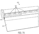
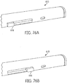
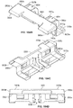
- the pusher extender 1324 can be formed with a cavity or pocket 1328.
- the cavity 1328 can be provided with one or more tabs 1330, which can be arranged vertically on the rear of the pusher extender 1324 so as to engage the pusher 520 adjacent to its edges.
- the tabs 1330 can extend from a plane formed by vertical rear surfaces on the rear of the pusher extender 1324.
- the pusher 520 or a pusher paddle can be received between the plane defined by the vertical rear surfaces on the pusher extender and the inner edges of the tabs 1330.
- the pusher extender 1324 can be provided with a rim 1340, which extends around a circumference of the pusher.
- the pusher extender 1324 can be provided with a series of projections 1332, which extend from a central wall 1338 formed inside the cavity 1328.
- the projections 1332 can be configured to align with horizontal grooves 525 formed on the pusher face 522 to provide for a secure fit of the pusher extender 1324 over the pusher paddle.
- installing the pusher extender 1324 over the pusher paddle creates a ratcheting sound as the projections 1332 engage the horizontal grooves 525 formed in the pusher face 522.
- the ratcheting sound can indicate to the user that the pusher extender 1324 has been properly installed into place.
- the pusher extender 1324 can be formed integral with the pusher in a molding operation or other formation process.
Landscapes
- Display Racks (AREA)
- Freezers Or Refrigerated Showcases (AREA)
Claims (12)
- Waren-Anzeigesystem, das aufweist:einen Teiler (550), der aufgebaut ist, um an einer Haltestruktur befestigt zu werden, wobei der Teiler (550) ein vorderes Ende (553) und ein hinteres Ende (555) umfasst;wobei der Teiler (550) eine Teilerwand (552) mit einer rechten Seitenfläche (552a) und einer linken Seitenfläche (552b) umfasst, wobei die Teilerwand (552) sich von einem Teilerboden (554) nach oben erstreckt, wobei der Teilerboden (554) eine obere Fläche (554a) und eine untere Fläche (555b) hat;wobei die Teilerwand (552) den Teilerboden (554) in einen ersten Seitenabschnitt (559) und einen zweiten Seitenabschnitt (551) trennt, wobei einer auf jeder Seite der Teilerwand (552) ist, wobei der erste Seitenabschnitt (559) einen rechten Seitenabschnitt auf der oberen Fläche (554a) des Teilerbodens (554) hat und der zweite Seitenabschnitt (551) einen linken Seitenabschnitt der oberen Fläche (554a) des Teilerbodens (554) umfasst;eine Barriere (556a), die durch eine Drehung zwischen einer eingeklappten Position und einer aufrechten Position beweglich ist, wobei die Barriere (556a) nahe an dem vorderen Ende (553) des Teilers (550) positioniert ist, so dass ein auf der oberen Oberfläche (554a) des ersten Seitenabschnitts (559) des Teilerbodens (554) positioniertes Produkt die Barriere (556a) berührt, wenn das Produkt sich in Richtung des vorderen Endes (553) des Teilers (550) bewegt;eine erste Drehmontagestruktur (563) nahe an dem vorderen Ende (553) des Teilers (550) und mit diesem verbunden und nahe an dem ersten Seitenabschnitt (559) des Teilerbodens (554), wobei die Barriere (556a) mit der ersten Drehmontagestruktur (563) verbunden ist;eine zweite Barriere (556b), die durch eine Drehung zwischen einer eingeklappten Position und einer aufrechten Position beweglich ist, wobei die zweite Barriere (556b) nahe an dem vorderen Ende (553) des Teilers (550) positioniert ist, so dass ein auf der oberen Fläche (554a) des zweiten Seitenabschnitts (559) des Teilerbodens (554) positioniertes zweites Produkt die Barriere (556b) berührt, wenn das zweite Produkt sich in Richtung des vorderen Endes (553) des Teilers (550) bewegt; undeine zweite Drehmontagestruktur (563) nahe an dem vorderen Ende (553) des Teilers (550) und mit diesem verbunden und nahe an dem zweiten Seitenabschnitt (551) des Teilerbodens (554), wobei die zweite Barriere (556b) mit der zweiten Drehmontagestruktur (563) verbunden ist.
- Waren-Anzeigesystem nach Anspruch 1, wobei die Barriere (556a) aufgebaut ist, um sich von der eingeklappten Position in die aufrechte Position zu drehen, wenn ein Produkt, das auf dem rechten Seitenabschnitt der oberen Fläche (554a) des Teilerbodens (554) positioniert ist, sich in Richtung des vorderen Endes (553) des Teilers (550) bewegt und die Barriere (554a) berührt, und die Barriere (556a) aufgebaut ist, um die Vorwärtsbewegung des Produkts zu beenden, wenn die Barriere (556a) in der aufrechten Position ist, und
wobei die zweite Barriere (556b) aufgebaut ist, um sich aus der eingeklappten Position in die aufrechte Position zu drehen, wenn ein zweites Produkt, das auf dem linken Seitenabschnitt der oberen Fläche (554a) des Teilerbodens (554) positioniert ist, sich in Richtung des vorderen Endes (553) des Teilers (550) bewegt und das zweite Produkt die zweite Barriere (556b) berührt, und die zweite Barriere (556b) aufgebaut ist, um die Bewegung des zweiten Produkts zu beenden, wenn die zweite Barriere (556b) in die aufrechte Position gebracht wird. - Waren-Anzeigesystem nach Anspruch 1, wobei jede Barriere (556a, 556b) einen Barrierengriff (567) umfasst und durch Ziehen oder Drücken des Barrierengriffs (567) manuell zwischen der aufrechten Position und der eingeklappten Position drehbar ist.
- Waren-Anzeigesystem nach Anspruch 1, wobei jede Barriere (556a, 556b) einen Klappwinkel (C) zwischen einer hinteren Fläche (569) der Barriere (556a, 556b) und der oberen Fläche (554a) des Teilerbodens (554) definiert, wenn die Barriere (556a, 556b) in der eingeklappten Position ist, wobei der Klappwinkel (C) zwischen etwa 45 Grad und etwa 20 Grad ist.
- Waren-Anzeigesystem nach Anspruch 4, wobei der Klappwinkel (C) etwa 20 Grad ist.
- Waren-Anzeigesystem nach Anspruch 4, wobei ein oberer Rand (568) der hinteren Fläche (569) jeder Barriere (556a, 556b) abgerundet ist.
- Waren-Anzeigesystem nach Anspruch 1, wobei die ersten und zweiten Drehmontagestrukturen (563) abnehmbar mit dem vorderen Ende (553) des Teilers (550) verbunden sind.
- Waren-Anzeigesystem nach Anspruch 1, wobei jede Drehmontagestruktur (563) eine vertikale Stütze (591), eine erste Drehhalterung (597a) eine zweite Drehhalterung (597b) und einen horizontalen Querträger (593) aufweist; wobei die vertikale Stütze (591) ein länglicher Pfosten ist, der in der Vertikalrichtung orientiert ist;
wobei der horizontale Querträger (593) ein länglicher Balken ist, der in einer seitlichen Richtung horizontal orientiert ist;
wobei die erste Drehhalterung (563a) mit einem ersten Abschnitt (593a) des horizontalen Querträgers (593) verbunden ist;
wobei die zweite Drehhalterung (563b) mit einem zweiten Abschnitt (593b) des horizontalen Querträgers (593) verbunden ist; und
die vertikale Stütze (591) einen Montageschlitz (598) umfasst, der in der vertikalen Stütze (591) montiert ist, wobei der Montageschlitz (598) aufgebaut ist, um zu einem vorderen Grat (599) des Teilers (550) zu passen, um die Drehmontagestruktur (563) abnehmbar mit dem vorderen Ende (553) des Teiler (550) zu verbinden. - Waren-Anzeigesystem nach Anspruch 8, wobei jede Barriere (556a, 556b) einen elastischen Ansatz (606) umfasst, der aufgebaut ist, um in einer Ansatzaussparung (604a) anzugreifen, die in einer Drehhalterung (597a, 597b) definiert ist, wenn die Barriere (556a, 556b) die aufrechte Position erreicht.
- Waren-Anzeigesystem nach Anspruch 1, das ferner einen Schiebermechanismus (520) aufweist, der in Richtung des vorderen Endes (553) des Teilers (55) vorgespannt ist und aufgebaut ist, um quer über den Teilerboden (554) zu gleiten, um ein Produkt in Richtung des vorderen Endes (553) des Teilers (555) zu bewegen, so dass das Produkt eine Barriere (556a, 556b) berührt, und wobei der Schiebermechanismus (520) eine Schieberfläche (522), einen Schieberboden (524), welcher sich von der Schieberfläche (522) nach vor erstreckt, und eine Spiralfeder mit einem gewendelten Ende und einem freien Ende aufweist.
- Waren-Anzeigesystem nach Anspruch 10, wobei der Schiebermechanismus (520) ferner ein Schiebererweiterungsglied (528) aufweist, das die Schieberfläche (522) vergrößert.
- Waren-Anzeigesystem nach Anspruch 1, wobei die Haltestruktur eine vordere Schiene (580) aufweist.
Priority Applications (2)
| Application Number | Priority Date | Filing Date | Title |
|---|---|---|---|
| EP18161313.4A EP3354166A1 (de) | 2013-01-28 | 2014-01-28 | Produktverwaltungsanzeigesystem |
| EP17208416.2A EP3323320B1 (de) | 2013-01-28 | 2014-01-28 | Produktverwaltungsanzeigesystem |
Applications Claiming Priority (5)
| Application Number | Priority Date | Filing Date | Title |
|---|---|---|---|
| US201361757479P | 2013-01-28 | 2013-01-28 | |
| US13/839,674 US8978904B2 (en) | 2005-09-12 | 2013-03-15 | Product management display system with trackless pusher mechanism |
| US201361861843P | 2013-08-02 | 2013-08-02 | |
| US14/136,029 US9138075B2 (en) | 2005-09-12 | 2013-12-20 | Product management display system |
| EP14703738.6A EP2770881B1 (de) | 2013-01-28 | 2014-01-28 | Produktverwaltungsanzeigesystem |
Related Parent Applications (2)
| Application Number | Title | Priority Date | Filing Date |
|---|---|---|---|
| EP14703738.6A Division EP2770881B1 (de) | 2013-01-28 | 2014-01-28 | Produktverwaltungsanzeigesystem |
| EP14703738.6A Division-Into EP2770881B1 (de) | 2013-01-28 | 2014-01-28 | Produktverwaltungsanzeigesystem |
Related Child Applications (4)
| Application Number | Title | Priority Date | Filing Date |
|---|---|---|---|
| EP18161313.4A Division EP3354166A1 (de) | 2013-01-28 | 2014-01-28 | Produktverwaltungsanzeigesystem |
| EP18161313.4A Division-Into EP3354166A1 (de) | 2013-01-28 | 2014-01-28 | Produktverwaltungsanzeigesystem |
| EP17208416.2A Division EP3323320B1 (de) | 2013-01-28 | 2014-01-28 | Produktverwaltungsanzeigesystem |
| EP17208416.2A Division-Into EP3323320B1 (de) | 2013-01-28 | 2014-01-28 | Produktverwaltungsanzeigesystem |
Publications (2)
| Publication Number | Publication Date |
|---|---|
| EP3087875A1 EP3087875A1 (de) | 2016-11-02 |
| EP3087875B1 true EP3087875B1 (de) | 2018-04-18 |
Family
ID=50071812
Family Applications (4)
| Application Number | Title | Priority Date | Filing Date |
|---|---|---|---|
| EP17208416.2A Active EP3323320B1 (de) | 2013-01-28 | 2014-01-28 | Produktverwaltungsanzeigesystem |
| EP14703738.6A Active EP2770881B1 (de) | 2013-01-28 | 2014-01-28 | Produktverwaltungsanzeigesystem |
| EP18161313.4A Pending EP3354166A1 (de) | 2013-01-28 | 2014-01-28 | Produktverwaltungsanzeigesystem |
| EP16152092.9A Active EP3087875B1 (de) | 2013-01-28 | 2014-01-28 | Produktverwaltungsanzeigesystem |
Family Applications Before (3)
| Application Number | Title | Priority Date | Filing Date |
|---|---|---|---|
| EP17208416.2A Active EP3323320B1 (de) | 2013-01-28 | 2014-01-28 | Produktverwaltungsanzeigesystem |
| EP14703738.6A Active EP2770881B1 (de) | 2013-01-28 | 2014-01-28 | Produktverwaltungsanzeigesystem |
| EP18161313.4A Pending EP3354166A1 (de) | 2013-01-28 | 2014-01-28 | Produktverwaltungsanzeigesystem |
Country Status (3)
| Country | Link |
|---|---|
| EP (4) | EP3323320B1 (de) |
| BR (1) | BR112015017972B1 (de) |
| WO (1) | WO2014117171A1 (de) |
Family Cites Families (12)
| Publication number | Priority date | Publication date | Assignee | Title |
|---|---|---|---|---|
| US6142317A (en) * | 1997-11-12 | 2000-11-07 | Merl; Milton J. | Gravity feed shelving system with track and pusher |
| US20040245197A1 (en) * | 2001-07-09 | 2004-12-09 | Mcelvaney Oliver | Shelf management systems |
| AU2002327441A1 (en) * | 2001-08-10 | 2003-02-24 | Mechtronics Corporation | Pusher-type display system |
| US6955269B2 (en) * | 2003-10-13 | 2005-10-18 | Display Technologies, Llc | Weighted pusher |
| US7506769B2 (en) * | 2004-12-07 | 2009-03-24 | Howerton Gary N | Pusher-type display system |
| US7395938B2 (en) * | 2005-02-18 | 2008-07-08 | Jo A. Merit | Method and apparatus for selective engagement of shelf divider structures within a shelf management system |
| US20070138114A1 (en) * | 2005-12-20 | 2007-06-21 | Tablex Inc. | Shelf tray assembly |
| US7971735B2 (en) * | 2006-02-16 | 2011-07-05 | Fasteners For Retail, Inc. | Merchandising system |
| EP1993407B1 (de) * | 2006-03-10 | 2017-07-26 | Rtc Industries, Inc. | Anzeige und vermarktungssystem mit mehreren komponenten |
| US7424957B1 (en) * | 2006-05-24 | 2008-09-16 | Henschel-Steinau, Inc. | Front-loading display and dispensing apparatus |
| US8056734B2 (en) | 2006-10-23 | 2011-11-15 | Rtc Industries, Inc. | Merchandising system with flippable column and/or item stop |
| US20080203256A1 (en) * | 2007-02-22 | 2008-08-28 | Excell Products, Inc. | Retention apparatus for stabilizing a merchandise display assembly on a shelf |
-
2014
- 2014-01-28 WO PCT/US2014/013425 patent/WO2014117171A1/en not_active Ceased
- 2014-01-28 EP EP17208416.2A patent/EP3323320B1/de active Active
- 2014-01-28 EP EP14703738.6A patent/EP2770881B1/de active Active
- 2014-01-28 EP EP18161313.4A patent/EP3354166A1/de active Pending
- 2014-01-28 EP EP16152092.9A patent/EP3087875B1/de active Active
- 2014-01-28 BR BR112015017972-0A patent/BR112015017972B1/pt not_active IP Right Cessation
Non-Patent Citations (1)
| Title |
|---|
| None * |
Also Published As
| Publication number | Publication date |
|---|---|
| EP3087875A1 (de) | 2016-11-02 |
| EP2770881A1 (de) | 2014-09-03 |
| EP3354166A1 (de) | 2018-08-01 |
| WO2014117171A1 (en) | 2014-07-31 |
| EP3323320A1 (de) | 2018-05-23 |
| BR112015017972A2 (pt) | 2017-07-11 |
| EP2770881B1 (de) | 2016-04-20 |
| BR112015017972B1 (pt) | 2021-09-21 |
| EP3323320B1 (de) | 2020-04-22 |
Similar Documents
| Publication | Publication Date | Title |
|---|---|---|
| US10905258B2 (en) | Product management display system | |
| US10702075B2 (en) | Product management display system | |
| US10226137B2 (en) | Product management display system | |
| US20140332481A1 (en) | Product management display system with trackless pusher mechanism | |
| US11344138B2 (en) | Product management display system | |
| EP3125727B1 (de) | Produktverwaltungsanzeigesystem | |
| EP3027086B1 (de) | Produktverwaltungsanzeigesystem | |
| EP3151705B1 (de) | Produktverwaltungsanzeigesystem | |
| EP2770881B1 (de) | Produktverwaltungsanzeigesystem |
Legal Events
| Date | Code | Title | Description |
|---|---|---|---|
| PUAI | Public reference made under article 153(3) epc to a published international application that has entered the european phase |
Free format text: ORIGINAL CODE: 0009012 |
|
| AC | Divisional application: reference to earlier application |
Ref document number: 2770881 Country of ref document: EP Kind code of ref document: P |
|
| AK | Designated contracting states |
Kind code of ref document: A1 Designated state(s): AL AT BE BG CH CY CZ DE DK EE ES FI FR GB GR HR HU IE IS IT LI LT LU LV MC MK MT NL NO PL PT RO RS SE SI SK SM TR |
|
| 17P | Request for examination filed |
Effective date: 20161018 |
|
| RBV | Designated contracting states (corrected) |
Designated state(s): AL AT BE BG CH CY CZ DE DK EE ES FI FR GB GR HR HU IE IS IT LI LT LU LV MC MK MT NL NO PL PT RO RS SE SI SK SM TR |
|
| STAA | Information on the status of an ep patent application or granted ep patent |
Free format text: STATUS: EXAMINATION IS IN PROGRESS |
|
| REG | Reference to a national code |
Ref country code: FR Ref legal event code: EL |
|
| 17Q | First examination report despatched |
Effective date: 20161201 |
|
| GRAP | Despatch of communication of intention to grant a patent |
Free format text: ORIGINAL CODE: EPIDOSNIGR1 |
|
| STAA | Information on the status of an ep patent application or granted ep patent |
Free format text: STATUS: GRANT OF PATENT IS INTENDED |
|
| INTG | Intention to grant announced |
Effective date: 20170922 |
|
| RIN1 | Information on inventor provided before grant (corrected) |
Inventor name: HARDY, STEPHEN |
|
| GRAS | Grant fee paid |
Free format text: ORIGINAL CODE: EPIDOSNIGR3 |
|
| GRAJ | Information related to disapproval of communication of intention to grant by the applicant or resumption of examination proceedings by the epo deleted |
Free format text: ORIGINAL CODE: EPIDOSDIGR1 |
|
| GRAL | Information related to payment of fee for publishing/printing deleted |
Free format text: ORIGINAL CODE: EPIDOSDIGR3 |
|
| STAA | Information on the status of an ep patent application or granted ep patent |
Free format text: STATUS: EXAMINATION IS IN PROGRESS |
|
| GRAP | Despatch of communication of intention to grant a patent |
Free format text: ORIGINAL CODE: EPIDOSNIGR1 |
|
| STAA | Information on the status of an ep patent application or granted ep patent |
Free format text: STATUS: GRANT OF PATENT IS INTENDED |
|
| INTC | Intention to grant announced (deleted) | ||
| GRAA | (expected) grant |
Free format text: ORIGINAL CODE: 0009210 |
|
| STAA | Information on the status of an ep patent application or granted ep patent |
Free format text: STATUS: THE PATENT HAS BEEN GRANTED |
|
| INTG | Intention to grant announced |
Effective date: 20180223 |
|
| AC | Divisional application: reference to earlier application |
Ref document number: 2770881 Country of ref document: EP Kind code of ref document: P |
|
| AK | Designated contracting states |
Kind code of ref document: B1 Designated state(s): AL AT BE BG CH CY CZ DE DK EE ES FI FR GB GR HR HU IE IS IT LI LT LU LV MC MK MT NL NO PL PT RO RS SE SI SK SM TR |
|
| REG | Reference to a national code |
Ref country code: GB Ref legal event code: FG4D |
|
| REG | Reference to a national code |
Ref country code: CH Ref legal event code: EP |
|
| REG | Reference to a national code |
Ref country code: AT Ref legal event code: REF Ref document number: 989499 Country of ref document: AT Kind code of ref document: T Effective date: 20180515 |
|
| REG | Reference to a national code |
Ref country code: IE Ref legal event code: FG4D |
|
| REG | Reference to a national code |
Ref country code: DE Ref legal event code: R096 Ref document number: 602014024283 Country of ref document: DE |
|
| REG | Reference to a national code |
Ref country code: NL Ref legal event code: MP Effective date: 20180418 |
|
| REG | Reference to a national code |
Ref country code: LT Ref legal event code: MG4D |
|
| PG25 | Lapsed in a contracting state [announced via postgrant information from national office to epo] |
Ref country code: NL Free format text: LAPSE BECAUSE OF FAILURE TO SUBMIT A TRANSLATION OF THE DESCRIPTION OR TO PAY THE FEE WITHIN THE PRESCRIBED TIME-LIMIT Effective date: 20180418 |
|
| PG25 | Lapsed in a contracting state [announced via postgrant information from national office to epo] |
Ref country code: NO Free format text: LAPSE BECAUSE OF FAILURE TO SUBMIT A TRANSLATION OF THE DESCRIPTION OR TO PAY THE FEE WITHIN THE PRESCRIBED TIME-LIMIT Effective date: 20180718 Ref country code: FI Free format text: LAPSE BECAUSE OF FAILURE TO SUBMIT A TRANSLATION OF THE DESCRIPTION OR TO PAY THE FEE WITHIN THE PRESCRIBED TIME-LIMIT Effective date: 20180418 Ref country code: BG Free format text: LAPSE BECAUSE OF FAILURE TO SUBMIT A TRANSLATION OF THE DESCRIPTION OR TO PAY THE FEE WITHIN THE PRESCRIBED TIME-LIMIT Effective date: 20180718 Ref country code: PL Free format text: LAPSE BECAUSE OF FAILURE TO SUBMIT A TRANSLATION OF THE DESCRIPTION OR TO PAY THE FEE WITHIN THE PRESCRIBED TIME-LIMIT Effective date: 20180418 Ref country code: AL Free format text: LAPSE BECAUSE OF FAILURE TO SUBMIT A TRANSLATION OF THE DESCRIPTION OR TO PAY THE FEE WITHIN THE PRESCRIBED TIME-LIMIT Effective date: 20180418 Ref country code: SE Free format text: LAPSE BECAUSE OF FAILURE TO SUBMIT A TRANSLATION OF THE DESCRIPTION OR TO PAY THE FEE WITHIN THE PRESCRIBED TIME-LIMIT Effective date: 20180418 Ref country code: ES Free format text: LAPSE BECAUSE OF FAILURE TO SUBMIT A TRANSLATION OF THE DESCRIPTION OR TO PAY THE FEE WITHIN THE PRESCRIBED TIME-LIMIT Effective date: 20180418 Ref country code: LT Free format text: LAPSE BECAUSE OF FAILURE TO SUBMIT A TRANSLATION OF THE DESCRIPTION OR TO PAY THE FEE WITHIN THE PRESCRIBED TIME-LIMIT Effective date: 20180418 |
|
| PG25 | Lapsed in a contracting state [announced via postgrant information from national office to epo] |
Ref country code: GR Free format text: LAPSE BECAUSE OF FAILURE TO SUBMIT A TRANSLATION OF THE DESCRIPTION OR TO PAY THE FEE WITHIN THE PRESCRIBED TIME-LIMIT Effective date: 20180719 Ref country code: HR Free format text: LAPSE BECAUSE OF FAILURE TO SUBMIT A TRANSLATION OF THE DESCRIPTION OR TO PAY THE FEE WITHIN THE PRESCRIBED TIME-LIMIT Effective date: 20180418 Ref country code: RS Free format text: LAPSE BECAUSE OF FAILURE TO SUBMIT A TRANSLATION OF THE DESCRIPTION OR TO PAY THE FEE WITHIN THE PRESCRIBED TIME-LIMIT Effective date: 20180418 Ref country code: LV Free format text: LAPSE BECAUSE OF FAILURE TO SUBMIT A TRANSLATION OF THE DESCRIPTION OR TO PAY THE FEE WITHIN THE PRESCRIBED TIME-LIMIT Effective date: 20180418 |
|
| REG | Reference to a national code |
Ref country code: AT Ref legal event code: MK05 Ref document number: 989499 Country of ref document: AT Kind code of ref document: T Effective date: 20180418 |
|
| REG | Reference to a national code |
Ref country code: DE Ref legal event code: R097 Ref document number: 602014024283 Country of ref document: DE |
|
| PG25 | Lapsed in a contracting state [announced via postgrant information from national office to epo] |
Ref country code: DK Free format text: LAPSE BECAUSE OF FAILURE TO SUBMIT A TRANSLATION OF THE DESCRIPTION OR TO PAY THE FEE WITHIN THE PRESCRIBED TIME-LIMIT Effective date: 20180418 Ref country code: AT Free format text: LAPSE BECAUSE OF FAILURE TO SUBMIT A TRANSLATION OF THE DESCRIPTION OR TO PAY THE FEE WITHIN THE PRESCRIBED TIME-LIMIT Effective date: 20180418 Ref country code: EE Free format text: LAPSE BECAUSE OF FAILURE TO SUBMIT A TRANSLATION OF THE DESCRIPTION OR TO PAY THE FEE WITHIN THE PRESCRIBED TIME-LIMIT Effective date: 20180418 Ref country code: RO Free format text: LAPSE BECAUSE OF FAILURE TO SUBMIT A TRANSLATION OF THE DESCRIPTION OR TO PAY THE FEE WITHIN THE PRESCRIBED TIME-LIMIT Effective date: 20180418 Ref country code: CZ Free format text: LAPSE BECAUSE OF FAILURE TO SUBMIT A TRANSLATION OF THE DESCRIPTION OR TO PAY THE FEE WITHIN THE PRESCRIBED TIME-LIMIT Effective date: 20180418 Ref country code: SK Free format text: LAPSE BECAUSE OF FAILURE TO SUBMIT A TRANSLATION OF THE DESCRIPTION OR TO PAY THE FEE WITHIN THE PRESCRIBED TIME-LIMIT Effective date: 20180418 |
|
| PLBE | No opposition filed within time limit |
Free format text: ORIGINAL CODE: 0009261 |
|
| STAA | Information on the status of an ep patent application or granted ep patent |
Free format text: STATUS: NO OPPOSITION FILED WITHIN TIME LIMIT |
|
| PG25 | Lapsed in a contracting state [announced via postgrant information from national office to epo] |
Ref country code: SM Free format text: LAPSE BECAUSE OF FAILURE TO SUBMIT A TRANSLATION OF THE DESCRIPTION OR TO PAY THE FEE WITHIN THE PRESCRIBED TIME-LIMIT Effective date: 20180418 |
|
| 26N | No opposition filed |
Effective date: 20190121 |
|
| PG25 | Lapsed in a contracting state [announced via postgrant information from national office to epo] |
Ref country code: SI Free format text: LAPSE BECAUSE OF FAILURE TO SUBMIT A TRANSLATION OF THE DESCRIPTION OR TO PAY THE FEE WITHIN THE PRESCRIBED TIME-LIMIT Effective date: 20180418 |
|
| PG25 | Lapsed in a contracting state [announced via postgrant information from national office to epo] |
Ref country code: MC Free format text: LAPSE BECAUSE OF FAILURE TO SUBMIT A TRANSLATION OF THE DESCRIPTION OR TO PAY THE FEE WITHIN THE PRESCRIBED TIME-LIMIT Effective date: 20180418 |
|
| REG | Reference to a national code |
Ref country code: CH Ref legal event code: PL |
|
| PG25 | Lapsed in a contracting state [announced via postgrant information from national office to epo] |
Ref country code: LU Free format text: LAPSE BECAUSE OF NON-PAYMENT OF DUE FEES Effective date: 20190128 |
|
| REG | Reference to a national code |
Ref country code: BE Ref legal event code: MM Effective date: 20190131 |
|
| REG | Reference to a national code |
Ref country code: IE Ref legal event code: MM4A |
|
| PG25 | Lapsed in a contracting state [announced via postgrant information from national office to epo] |
Ref country code: BE Free format text: LAPSE BECAUSE OF NON-PAYMENT OF DUE FEES Effective date: 20190131 |
|
| PG25 | Lapsed in a contracting state [announced via postgrant information from national office to epo] |
Ref country code: CH Free format text: LAPSE BECAUSE OF NON-PAYMENT OF DUE FEES Effective date: 20190131 Ref country code: LI Free format text: LAPSE BECAUSE OF NON-PAYMENT OF DUE FEES Effective date: 20190131 |
|
| PG25 | Lapsed in a contracting state [announced via postgrant information from national office to epo] |
Ref country code: IE Free format text: LAPSE BECAUSE OF NON-PAYMENT OF DUE FEES Effective date: 20190128 |
|
| PG25 | Lapsed in a contracting state [announced via postgrant information from national office to epo] |
Ref country code: TR Free format text: LAPSE BECAUSE OF FAILURE TO SUBMIT A TRANSLATION OF THE DESCRIPTION OR TO PAY THE FEE WITHIN THE PRESCRIBED TIME-LIMIT Effective date: 20180418 |
|
| PG25 | Lapsed in a contracting state [announced via postgrant information from national office to epo] |
Ref country code: MT Free format text: LAPSE BECAUSE OF NON-PAYMENT OF DUE FEES Effective date: 20190128 Ref country code: PT Free format text: LAPSE BECAUSE OF FAILURE TO SUBMIT A TRANSLATION OF THE DESCRIPTION OR TO PAY THE FEE WITHIN THE PRESCRIBED TIME-LIMIT Effective date: 20180820 |
|
| PG25 | Lapsed in a contracting state [announced via postgrant information from national office to epo] |
Ref country code: CY Free format text: LAPSE BECAUSE OF FAILURE TO SUBMIT A TRANSLATION OF THE DESCRIPTION OR TO PAY THE FEE WITHIN THE PRESCRIBED TIME-LIMIT Effective date: 20180418 |
|
| PG25 | Lapsed in a contracting state [announced via postgrant information from national office to epo] |
Ref country code: IS Free format text: LAPSE BECAUSE OF FAILURE TO SUBMIT A TRANSLATION OF THE DESCRIPTION OR TO PAY THE FEE WITHIN THE PRESCRIBED TIME-LIMIT Effective date: 20180818 |
|
| PG25 | Lapsed in a contracting state [announced via postgrant information from national office to epo] |
Ref country code: HU Free format text: LAPSE BECAUSE OF FAILURE TO SUBMIT A TRANSLATION OF THE DESCRIPTION OR TO PAY THE FEE WITHIN THE PRESCRIBED TIME-LIMIT; INVALID AB INITIO Effective date: 20140128 |
|
| PG25 | Lapsed in a contracting state [announced via postgrant information from national office to epo] |
Ref country code: MK Free format text: LAPSE BECAUSE OF FAILURE TO SUBMIT A TRANSLATION OF THE DESCRIPTION OR TO PAY THE FEE WITHIN THE PRESCRIBED TIME-LIMIT Effective date: 20180418 |
|
| PGFP | Annual fee paid to national office [announced via postgrant information from national office to epo] |
Ref country code: IT Payment date: 20230120 Year of fee payment: 10 |
|
| PG25 | Lapsed in a contracting state [announced via postgrant information from national office to epo] |
Ref country code: IT Free format text: LAPSE BECAUSE OF NON-PAYMENT OF DUE FEES Effective date: 20240128 |
|
| PGFP | Annual fee paid to national office [announced via postgrant information from national office to epo] |
Ref country code: GB Payment date: 20260127 Year of fee payment: 13 |
|
| PGFP | Annual fee paid to national office [announced via postgrant information from national office to epo] |
Ref country code: DE Payment date: 20260128 Year of fee payment: 13 |
|
| PGFP | Annual fee paid to national office [announced via postgrant information from national office to epo] |
Ref country code: FR Payment date: 20260126 Year of fee payment: 13 |