EP3087265B1 - Aircraft propulsion assembly with fire extinguishing system and ventilation method - Google Patents
Aircraft propulsion assembly with fire extinguishing system and ventilation method Download PDFInfo
- Publication number
- EP3087265B1 EP3087265B1 EP14833513.6A EP14833513A EP3087265B1 EP 3087265 B1 EP3087265 B1 EP 3087265B1 EP 14833513 A EP14833513 A EP 14833513A EP 3087265 B1 EP3087265 B1 EP 3087265B1
- Authority
- EP
- European Patent Office
- Prior art keywords
- engine
- nacelle
- propulsion assembly
- cavity
- pipe
- Prior art date
- Legal status (The legal status is an assumption and is not a legal conclusion. Google has not performed a legal analysis and makes no representation as to the accuracy of the status listed.)
- Active
Links
- 238000000034 method Methods 0.000 title claims description 5
- 238000009423 ventilation Methods 0.000 title description 10
- 239000003795 chemical substances by application Substances 0.000 description 15
- 210000003462 vein Anatomy 0.000 description 5
- 238000002485 combustion reaction Methods 0.000 description 3
- 238000001514 detection method Methods 0.000 description 3
- 230000006835 compression Effects 0.000 description 2
- 238000007906 compression Methods 0.000 description 2
- 238000009795 derivation Methods 0.000 description 2
- 230000037452 priming Effects 0.000 description 2
- 238000011144 upstream manufacturing Methods 0.000 description 2
- 229920004449 Halon® Polymers 0.000 description 1
- 238000005273 aeration Methods 0.000 description 1
- 230000005540 biological transmission Effects 0.000 description 1
- 230000005465 channeling Effects 0.000 description 1
- PXBRQCKWGAHEHS-UHFFFAOYSA-N dichlorodifluoromethane Chemical compound FC(F)(Cl)Cl PXBRQCKWGAHEHS-UHFFFAOYSA-N 0.000 description 1
- 230000009970 fire resistant effect Effects 0.000 description 1
- 239000003999 initiator Substances 0.000 description 1
- 238000012423 maintenance Methods 0.000 description 1
- 239000000463 material Substances 0.000 description 1
- 230000002093 peripheral effect Effects 0.000 description 1
- 239000003380 propellant Substances 0.000 description 1
Images
Classifications
-
- B—PERFORMING OPERATIONS; TRANSPORTING
- B64—AIRCRAFT; AVIATION; COSMONAUTICS
- B64D—EQUIPMENT FOR FITTING IN OR TO AIRCRAFT; FLIGHT SUITS; PARACHUTES; ARRANGEMENTS OR MOUNTING OF POWER PLANTS OR PROPULSION TRANSMISSIONS IN AIRCRAFT
- B64D45/00—Aircraft indicators or protectors not otherwise provided for
-
- B—PERFORMING OPERATIONS; TRANSPORTING
- B64—AIRCRAFT; AVIATION; COSMONAUTICS
- B64D—EQUIPMENT FOR FITTING IN OR TO AIRCRAFT; FLIGHT SUITS; PARACHUTES; ARRANGEMENTS OR MOUNTING OF POWER PLANTS OR PROPULSION TRANSMISSIONS IN AIRCRAFT
- B64D29/00—Power-plant nacelles, fairings, or cowlings
-
- A—HUMAN NECESSITIES
- A62—LIFE-SAVING; FIRE-FIGHTING
- A62C—FIRE-FIGHTING
- A62C3/00—Fire prevention, containment or extinguishing specially adapted for particular objects or places
- A62C3/07—Fire prevention, containment or extinguishing specially adapted for particular objects or places in vehicles, e.g. in road vehicles
- A62C3/08—Fire prevention, containment or extinguishing specially adapted for particular objects or places in vehicles, e.g. in road vehicles in aircraft
-
- B—PERFORMING OPERATIONS; TRANSPORTING
- B64—AIRCRAFT; AVIATION; COSMONAUTICS
- B64C—AEROPLANES; HELICOPTERS
- B64C7/00—Structures or fairings not otherwise provided for
- B64C7/02—Nacelles
-
- F—MECHANICAL ENGINEERING; LIGHTING; HEATING; WEAPONS; BLASTING
- F01—MACHINES OR ENGINES IN GENERAL; ENGINE PLANTS IN GENERAL; STEAM ENGINES
- F01D—NON-POSITIVE DISPLACEMENT MACHINES OR ENGINES, e.g. STEAM TURBINES
- F01D25/00—Component parts, details, or accessories, not provided for in, or of interest apart from, other groups
- F01D25/24—Casings; Casing parts, e.g. diaphragms, casing fastenings
-
- F—MECHANICAL ENGINEERING; LIGHTING; HEATING; WEAPONS; BLASTING
- F02—COMBUSTION ENGINES; HOT-GAS OR COMBUSTION-PRODUCT ENGINE PLANTS
- F02C—GAS-TURBINE PLANTS; AIR INTAKES FOR JET-PROPULSION PLANTS; CONTROLLING FUEL SUPPLY IN AIR-BREATHING JET-PROPULSION PLANTS
- F02C7/00—Features, components parts, details or accessories, not provided for in, or of interest apart form groups F02C1/00 - F02C6/00; Air intakes for jet-propulsion plants
- F02C7/12—Cooling of plants
-
- F—MECHANICAL ENGINEERING; LIGHTING; HEATING; WEAPONS; BLASTING
- F02—COMBUSTION ENGINES; HOT-GAS OR COMBUSTION-PRODUCT ENGINE PLANTS
- F02C—GAS-TURBINE PLANTS; AIR INTAKES FOR JET-PROPULSION PLANTS; CONTROLLING FUEL SUPPLY IN AIR-BREATHING JET-PROPULSION PLANTS
- F02C7/00—Features, components parts, details or accessories, not provided for in, or of interest apart form groups F02C1/00 - F02C6/00; Air intakes for jet-propulsion plants
- F02C7/24—Heat or noise insulation
- F02C7/25—Fire protection or prevention
-
- B—PERFORMING OPERATIONS; TRANSPORTING
- B64—AIRCRAFT; AVIATION; COSMONAUTICS
- B64D—EQUIPMENT FOR FITTING IN OR TO AIRCRAFT; FLIGHT SUITS; PARACHUTES; ARRANGEMENTS OR MOUNTING OF POWER PLANTS OR PROPULSION TRANSMISSIONS IN AIRCRAFT
- B64D45/00—Aircraft indicators or protectors not otherwise provided for
- B64D2045/009—Fire detection or protection; Erosion protection, e.g. from airborne particles
-
- F—MECHANICAL ENGINEERING; LIGHTING; HEATING; WEAPONS; BLASTING
- F05—INDEXING SCHEMES RELATING TO ENGINES OR PUMPS IN VARIOUS SUBCLASSES OF CLASSES F01-F04
- F05D—INDEXING SCHEME FOR ASPECTS RELATING TO NON-POSITIVE-DISPLACEMENT MACHINES OR ENGINES, GAS-TURBINES OR JET-PROPULSION PLANTS
- F05D2220/00—Application
- F05D2220/30—Application in turbines
- F05D2220/32—Application in turbines in gas turbines
- F05D2220/323—Application in turbines in gas turbines for aircraft propulsion, e.g. jet engines
-
- Y—GENERAL TAGGING OF NEW TECHNOLOGICAL DEVELOPMENTS; GENERAL TAGGING OF CROSS-SECTIONAL TECHNOLOGIES SPANNING OVER SEVERAL SECTIONS OF THE IPC; TECHNICAL SUBJECTS COVERED BY FORMER USPC CROSS-REFERENCE ART COLLECTIONS [XRACs] AND DIGESTS
- Y02—TECHNOLOGIES OR APPLICATIONS FOR MITIGATION OR ADAPTATION AGAINST CLIMATE CHANGE
- Y02T—CLIMATE CHANGE MITIGATION TECHNOLOGIES RELATED TO TRANSPORTATION
- Y02T50/00—Aeronautics or air transport
- Y02T50/60—Efficient propulsion technologies, e.g. for aircraft
Definitions
- the present invention relates to the field of ventilation of an aircraft propulsion unit.
- An aircraft propulsion unit comprises a motor and a nacelle surrounding this engine which is generally a turbomachine.
- the nacelle comprises a housing of revolution delimiting an annular flow stream of a flow of air around the engine, this air flow being called secondary flow in the case of a turbomachine with a double flow.
- the nacelle defines around the housing a first annular cavity.
- Some equipment of the propulsion unit are mounted in the nacelle, that is to say in the aforementioned annular cavity, and can be fixed on its housing.
- the outer wall of the nacelle generally comprises removable covers to allow access to these devices during a maintenance operation.
- the engine comprises an internal annular vein of flow of an air flow called primary flow in the case of a turbomachine with a double flow.
- the engine comprises coaxial revolution housings which are surrounded by a wall of revolution which delimits internally the vein of the secondary flow. This wall extends away from the engine casings and defines around them a second annular cavity. Some equipment is mounted in this second annular cavity.
- the equipment mounted in the cavities of the propulsion unit are more or less sensitive to heat and are ventilated during operation. This is particularly the case of a computer or onboard computer type EEC, which allows in particular to control actuators of the engine to optimize the performance of the turbomachine ( FR-B1-2 960 912 ).
- This computer is usually mounted with other equipment ( Accessory Gear Box (AGB) , exchangers, etc.) in the basket.
- AGB Accessory Gear Box
- exchangers etc.
- the latter In order to ventilate the internal cavity of the nacelle, the latter comprises an air intake scoop in flight, the air drawn is then evacuated by an air outlet grille of the nacelle.
- this ventilation is almost non-existent and the natural convection in the annular space of the nacelle may be insufficient to ensure the ventilation of its equipment.
- the computer releases a significant thermal power in operation that must be dissipated, whether the engine is running or is stopped.
- the hot parts of the engine continue to radiate and heat colder peripheral parts of the engine, which can thus, at the engine stop, reach temperatures close or even higher than their temperatures when the engine is running.
- an aircraft propulsion unit is equipped with a fire extinguishing system that can appear in the engine and / or in the nacelle.
- This extinguishing system comprises means for supplying extinguishing agent of at least one extinguishing agent distribution pipe, which opens into a cavity of the engine and / or a cavity of the nacelle.
- This extinguishing system is generally associated with a fire detection system (of the FDU type, of the English Fire Detection Unit ) which comprises sensors mounted on the engine and / or the nacelle and which is intended to emit a signal warning to the pilot of the aircraft when at least one of the sensors detects the appearance of a fire.
- the invention proposes a propulsion unit for an aircraft, comprising an engine, a nacelle surrounding the engine, and a fire extinguishing system that can appear in the engine and / or in the nacelle, this extinguishing system comprising means for supplying extinguishing agent of at least one distribution pipe of said extinguishing agent, which opens into a cavity of the engine and / or a cavity of the nacelle, characterized in that it further comprises means for supplying air of said at least one pipe for ventilation of the cavity or cavities.
- the invention therefore consists in assigning to a known means a new additional function.
- the distribution channel of the extinguishing agent of the fire extinguishing system is, as in the prior art, used to distribute this agent in the cavity or cavities of the propulsion unit in the event that a fire appears.
- this pipe also serves to ventilate this or these cavities.
- the pipe is associated with air supply means that delivers a flow of air to the pipe, this air flow is then routed through the pipe to the cavity or cavities to ventilate.
- the invention thus makes it possible to use an existing means (ducting) for conveying ventilation air to a cavity of the nacelle and / or the engine, this existing means being used for a very different thing in the prior art. (extinguishing agent distribution).
- the extinguishing system of a propulsion system is rarely used. Its pipe may be to ventilate the cavities of the propulsion unit, even when the engine is stopped. Indeed, the operation of the air supply means of the pipe are advantageously independent of the engine and can therefore operate when the engine stops. The equipment mounted in the cavities of the set propellant can be ventilated when the engine is stopped, which increases the life of this equipment.
- the air supply means preferably comprise a fan.
- This fan can be an electric fan.
- the supply means may be connected by a valve and / or a non-return valve to the at least one pipe. They can be connected to this pipe by a derivation Y for example.
- the feeding means can be housed in the nacelle.
- connection between a propulsion unit and its pylon generally comprises a firewall adapted to limit the transmission of a fire that would occur in the propulsion system.
- the supply means are thus protected from a fire that could appear in the nacelle.
- the supply means can be configured to deliver an air flow rate of between 1 and 500 g / s.
- the pipe may comprise at least one outlet which is located near an air inlet scoop of the nacelle or the engine.
- the present invention also relates to a method for ventilating a cavity of an engine and / or a cavity of a nacelle of an aircraft propulsion unit, this propulsion unit comprising a fire extinguishing system. which may appear in the engine and / or in the nacelle, this extinguishing system comprising means for supplying extinguishing agent with at least one distribution pipe for said extinguishing agent which opens into the engine cavity and / or the engine cavity.
- the nacelle characterized in that it consists in supplying air to said at least one pipe.
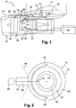
- FIG. 1 represents a propulsion unit 10 of an aircraft, this propulsion unit comprising a pylon 12 connecting to a structural part of the aircraft, which is here a wing 14 of the aircraft.
- the propulsion unit 10 comprises a motor 16 of the turbomachine type surrounded by a nacelle 18, the nacelle 18 defining a first annular stream 20 of flow of a secondary flow around the engine which comprises a second internal vein (not shown) of flow of a primary flow.
- the motor 16 typically comprises, from upstream to downstream, in the flow flow direction, a fan, at least one compression module, a combustion chamber, at least one turbine module, and a gas ejection nozzle. of combustion.
- the blower motor 16 is surrounded by a housing 22 of the nacelle 18, which is itself surrounded by a revolution wall 24 of the nacelle.
- Equipment is mounted in the annular cavity 26 delimited by the outer wall 24 and the casing 22 of the nacelle 18.
- the compression module, the combustion chamber, and the turbine module comprise outer casings 28 which are surrounded by a wall of revolution 30.
- This wall 30 delimits internally the vein 20 of the secondary flow and extends away from the outer housings 28 to define therewith an annular cavity 32 in which are also housed equipment.
- the propulsion unit 10 further comprises a fire extinguishing system that can appear in the engine 16 and / or in the nacelle 18.
- This extinguishing system comprises means 34 for supplying extinguishing agent of at least a pipe 36 for distributing the extinguishing agent.
- this duct 36 may comprise several inputs (here two in number) which are each connected to supply means 34, and several outputs 38 (here two in number).
- the duct 36 comprises a first outlet 38 in the cavity 26 of the nacelle 18 and a second outlet 40 in the cavity 32 of the motor 16.
- Each outlet 38, 40 here has a Y shape and comprises two orifices. discharge outlet for the projection of extinguishing agent in directions substantially tangential to the housing 22 or housings 28.
- the outlet 38 is preferably located near an air inlet scoop of the nacelle 16 (for the ventilation of the cavity 26 in operation of the engine) and the outlet 40 is preferably located near an air intake scoop of the engine (for ventilation of the cavity 32 in operation of the engine).
- outlets 38 and 40 are oriented to cooperate respectively with the air intake scoops of the nacelle 18 and the motor 16 to generate flows in similar directions. This prevents the extinguishing agent from leaving the areas to extinguish before filling.
- the aeration by the scoop or the invention is similar and simplifies the management of ventilation flows.
- the pipe 36 is made of a fire-resistant material and in particular at very high temperatures (for example higher than 1000 ° C.).
- the supply means 34 may comprise a reservoir of extinguishing agent (such as Halon for example) under pressure, an outlet of which is connected to an inlet of the pipe 36 by a priming system such as a pyrotechnic initiator.
- a priming system such as a pyrotechnic initiator. This priming system is controlled remotely by the pilot of the aircraft, from the cockpit of the aircraft.
- the extinguishing system is associated with a fire detection system 42 (for example of the FDU type) which is connected to sensors 44 mounted on the engine 16 and the nacelle 18 and which are each intended to emit an alert signal. for the attention of the pilot of the aircraft when at least one of the sensors 44 detects the appearance of a fire.
- the sensors 44 comprise for example thermocouples.
- the supply means 34 are generally mounted in the perimeter of the aircraft, this perimeter being here schematically delimited by the dashed lines 46 and comprising the pylon 12.
- the duct 36 extends from the supply means 34 The duct 36 must therefore pass through the vein of the secondary flow 20 and may for this purpose be housed in a tubular arm for the passage of servitudes of an intermediate casing of the motor.
- the dashed lines 46 symbolize a firewall to be crossed, it is therefore necessary at this point the minimum of pipe to limit the holes in this wall.
- means are provided for supplying air to the duct 36, this air being intended to be conveyed through the duct 36 to the cavities 26, 32 for ventilation.
- the air supply means comprise an electric fan 48 whose air outlet 50 is connected to the pipe 36, in the vicinity of its inlet 52 connected to the supply means 34.
- Y derivation in Y (from preferably upstream of the firewall)
- one of the lateral branches is connected to the fan 48
- the other lateral branch is connected to the supply means 34
- the middle branch is connected to the cavities 26, 32.
- connection between the fan 48 and the pipe 36 may comprise a solenoid valve or a non-return valve.
- the fan 48 can be configured to deliver an air flow rate of between 1 and 500 g / s.
- the fan 48 is preferably electrically controlled by independent control means of the motor 16 so that it can operate at engine stop. These control means are for example integrated into the electronic network of the aircraft.
- the fan 48 is housed in the tower 12.
- the variant embodiment of the invention represented in figure 4 differs from the embodiment described in the foregoing essentially in that the fan 48 is housed in the nacelle 18, that is to say in the annular cavity 26 of the nacelle.
- the fan 48 may be electrically controlled by engine control means which are configured to operate and remain operational at the engine stop.
- the invention can be applied to a propulsion unit 10 fixed to a wing 14 of an aircraft, the pylon 12 then being located at 12 o'clock (twelve hours) by analogy with the dial of a clock.
- the invention can be applied to a propulsion unit 10 attached to the fuselage of the aircraft, the pylon 12 being then for example located at 3 o'clock or 9 o'clock. It is also conceivable that the invention is applied to other types of propulsion units such as those at least partially buried in the fuselage of the aircraft.
Description
La présente invention concerne le domaine de la ventilation d'un ensemble propulsif d'aéronef.The present invention relates to the field of ventilation of an aircraft propulsion unit.
Un ensemble propulsif d'aéronef comprend un moteur et une nacelle entourant ce moteur qui est en général une turbomachine. La nacelle comprend un carter de révolution délimitant une veine annulaire d'écoulement d'un flux d'air autour du moteur, ce flux d'air étant appelé flux secondaire dans le cas d'une turbomachine à double flux. La nacelle définit autour du carter une première cavité annulaire. Certains équipements de l'ensemble propulsif sont montés dans la nacelle, c'est-à-dire dans la cavité annulaire précitée, et peuvent être fixés sur son carter. La paroi externe de la nacelle comprend en général des capots amovibles pour autoriser l'accès à ces équipements pendant une opération de maintenance.An aircraft propulsion unit comprises a motor and a nacelle surrounding this engine which is generally a turbomachine. The nacelle comprises a housing of revolution delimiting an annular flow stream of a flow of air around the engine, this air flow being called secondary flow in the case of a turbomachine with a double flow. The nacelle defines around the housing a first annular cavity. Some equipment of the propulsion unit are mounted in the nacelle, that is to say in the aforementioned annular cavity, and can be fixed on its housing. The outer wall of the nacelle generally comprises removable covers to allow access to these devices during a maintenance operation.
Le moteur comprend une veine annulaire interne d'écoulement d'un flux d'air appelé flux primaire dans le cas d'une turbomachine à double flux. Le moteur comprend des carters de révolution coaxiaux qui sont entourés par une paroi de révolution qui délimite intérieurement la veine du flux secondaire. Cette paroi s'étend à distance des carters du moteur et définit autour d'eux une seconde cavité annulaire. Certains équipements sont montés dans cette seconde cavité annulaire.The engine comprises an internal annular vein of flow of an air flow called primary flow in the case of a turbomachine with a double flow. The engine comprises coaxial revolution housings which are surrounded by a wall of revolution which delimits internally the vein of the secondary flow. This wall extends away from the engine casings and defines around them a second annular cavity. Some equipment is mounted in this second annular cavity.
Les équipements montés dans les cavités de l'ensemble propulsif sont plus ou moins sensibles à la chaleur et sont ventilés en fonctionnement. C'est notamment le cas d'un calculateur ou ordinateur embarqué du type EEC, qui permet notamment de contrôler des actionneurs du moteur en vue d'optimiser les performances de la turbomachine (
En vue de la ventilation de la cavité interne de la nacelle, celle-ci comprend une écope de prélèvement d'air en vol, l'air prélevé étant ensuite évacué par une grille de sortie d'air de la nacelle. Cependant, au sol, cette ventilation est quasi-inexistante et la convection naturelle dans l'espace annulaire de la nacelle peut se révéler insuffisante pour assurer la ventilation de ses équipements. Le calculateur dégage une puissance thermique importante en fonctionnement qu'il faut dissiper, que le moteur fonctionne ou soit à l'arrêt. De plus, même lorsque le moteur est à l'arrêt postérieurement à un fonctionnement, les parties chaudes du moteur continuent de rayonner et de chauffer des parties périphériques plus froides du moteur, qui peuvent ainsi, à l'arrêt moteur, atteindre des températures proches voire supérieures à leurs températures lorsque le moteur fonctionne.In order to ventilate the internal cavity of the nacelle, the latter comprises an air intake scoop in flight, the air drawn is then evacuated by an air outlet grille of the nacelle. However, on the ground, this ventilation is almost non-existent and the natural convection in the annular space of the nacelle may be insufficient to ensure the ventilation of its equipment. The computer releases a significant thermal power in operation that must be dissipated, whether the engine is running or is stopped. In addition, even when the engine is stopped after operation, the hot parts of the engine continue to radiate and heat colder peripheral parts of the engine, which can thus, at the engine stop, reach temperatures close or even higher than their temperatures when the engine is running.
Il existe donc un réel besoin d'un système capable de ventiler ce type de cavité d'un ensemble propulsif, même lorsque le moteur est à l'arrêt.There is therefore a real need for a system capable of ventilating this type of cavity of a propulsion unit, even when the engine is stopped.
Par ailleurs, un ensemble propulsif d'aéronef est équipé d'un système d'extinction d'un feu pouvant apparaître dans le moteur et/ou dans la nacelle. Ce système d'extinction comporte des moyens d'alimentation en agent extincteur d'au moins une canalisation de distribution de l'agent extincteur, qui débouche dans une cavité du moteur et/ou une cavité de la nacelle. Ce système d'extinction est en général associé à un système de détection de feu (du type FDU, de l'anglais Fire Detection Unit) qui comprend des capteurs montés sur le moteur et/ou la nacelle et qui est destiné à émettre un signal d'alerte à l'attention du pilote de l'aéronef lorsqu'au moins l'un des capteurs détecte l'apparition d'un feu.Furthermore, an aircraft propulsion unit is equipped with a fire extinguishing system that can appear in the engine and / or in the nacelle. This extinguishing system comprises means for supplying extinguishing agent of at least one extinguishing agent distribution pipe, which opens into a cavity of the engine and / or a cavity of the nacelle. This extinguishing system is generally associated with a fire detection system (of the FDU type, of the English Fire Detection Unit ) which comprises sensors mounted on the engine and / or the nacelle and which is intended to emit a signal warning to the pilot of the aircraft when at least one of the sensors detects the appearance of a fire.
Dans la technique actuelle, la canalisation du système d'extinction ne sert qu'à la distribution de l'agent extincteur. Comme les cas d'apparition d'un feu sont rares, cette canalisation n'est en général jamais utilisée. Elle est toutefois toujours présente dans un ensemble propulsif d'aéronef pour des raisons de sécurité et de certification. Un système d'extinction d'un feu selon la technique antérieure est divulgué dans
L'invention propose un ensemble propulsif d'aéronef, comportant un moteur, une nacelle entourant le moteur, et un système d'extinction d'un feu pouvant apparaître dans le moteur et/ou dans la nacelle, ce système d'extinction comportant des moyens d'alimentation en agent extincteur d'au moins une canalisation de distribution dudit agent extincteur, qui débouche dans une cavité du moteur et/ou une cavité de la nacelle, caractérisé en ce qu'il comprend en outre des moyens d'alimentation en air de ladite au moins une canalisation en vue de la ventilation de la ou les cavités.The invention proposes a propulsion unit for an aircraft, comprising an engine, a nacelle surrounding the engine, and a fire extinguishing system that can appear in the engine and / or in the nacelle, this extinguishing system comprising means for supplying extinguishing agent of at least one distribution pipe of said extinguishing agent, which opens into a cavity of the engine and / or a cavity of the nacelle, characterized in that it further comprises means for supplying air of said at least one pipe for ventilation of the cavity or cavities.
L'invention consiste donc à affecter à un moyen connu une fonction supplémentaire nouvelle. En effet, la canalisation de distribution de l'agent extincteur du système d'extinction de feu est, comme dans la technique antérieure, utilisée pour distribuer cet agent dans la ou les cavités de l'ensemble propulsif dans le cas où un feu apparaîtrait. Selon l'invention, cette canalisation sert en outre à ventiler cette ou ces cavités. La canalisation est pour cela associée à des moyens d'alimentation en air qui délivre un débit d'air à la canalisation, ce débit d'air étant alors acheminé par la canalisation jusqu'à la ou les cavités à ventiler. L'invention permet donc d'utiliser un moyen existant (canalisation) pour acheminer de l'air de ventilation jusqu'à une cavité de la nacelle et/ou du moteur, ce moyen existant étant utilisé pour une toute autre chose dans la technique antérieure (distribution d'agent extincteur). Comme indiqué dans ce qui précède, le système d'extinction d'un ensemble propulsif est rarement utilisé. Sa canalisation peut dont l'être pour ventiler les cavités de l'ensemble propulsif, même lorsque le moteur est à l'arrêt. En effet, le fonctionnement des moyens d'alimentation en air de la canalisation sont avantageusement indépendants du moteur et peuvent donc fonctionner à l'arrêt du moteur. Les équipements montés dans les cavités de l'ensemble propulsif peuvent ainsi être ventilés lorsque le moteur est à l'arrêt, ce qui permet d'augmenter la durée de vie de ces équipements.The invention therefore consists in assigning to a known means a new additional function. Indeed, the distribution channel of the extinguishing agent of the fire extinguishing system is, as in the prior art, used to distribute this agent in the cavity or cavities of the propulsion unit in the event that a fire appears. According to the invention, this pipe also serves to ventilate this or these cavities. The pipe is associated with air supply means that delivers a flow of air to the pipe, this air flow is then routed through the pipe to the cavity or cavities to ventilate. The invention thus makes it possible to use an existing means (ducting) for conveying ventilation air to a cavity of the nacelle and / or the engine, this existing means being used for a very different thing in the prior art. (extinguishing agent distribution). As indicated above, the extinguishing system of a propulsion system is rarely used. Its pipe may be to ventilate the cavities of the propulsion unit, even when the engine is stopped. Indeed, the operation of the air supply means of the pipe are advantageously independent of the engine and can therefore operate when the engine stops. The equipment mounted in the cavities of the set propellant can be ventilated when the engine is stopped, which increases the life of this equipment.
Les moyens d'alimentation en air comprennent de préférence un ventilateur. Ce ventilateur peut être un ventilateur électrique.The air supply means preferably comprise a fan. This fan can be an electric fan.
Les moyens d'alimentation peuvent être reliés par une vanne et/ou un clapet anti-retour à ladite au moins une canalisation. Ils peuvent être reliés à cette canalisation par une dérivation en Y par exemple.The supply means may be connected by a valve and / or a non-return valve to the at least one pipe. They can be connected to this pipe by a derivation Y for example.
Les moyens d'alimentation peuvent être logés dans la nacelle.The feeding means can be housed in the nacelle.
En variante, ils peuvent être logés dans un pylône de liaison de l'ensemble propulsif à l'aéronef. La liaison entre un ensemble propulsif et son pylône comprend généralement une paroi anti-feu adaptée à limiter la transmission d'un feu qui surviendrait dans l'ensemble propulsif. Les moyens d'alimentation sont ainsi protégés d'un feu qui pourrait apparaître dans la nacelle.Alternatively, they can be housed in a connecting pylon of the propulsion system to the aircraft. The connection between a propulsion unit and its pylon generally comprises a firewall adapted to limit the transmission of a fire that would occur in the propulsion system. The supply means are thus protected from a fire that could appear in the nacelle.
Les moyens d'alimentation peuvent être configurés pour délivrer un débit d'air compris entre 1 et 500g/s.The supply means can be configured to deliver an air flow rate of between 1 and 500 g / s.
Avantageusement, la canalisation peut comprendre au moins une sortie qui est située à proximité d'une écope d'entrée d'air de la nacelle ou du moteur.Advantageously, the pipe may comprise at least one outlet which is located near an air inlet scoop of the nacelle or the engine.
La présente invention concerne également un procédé de ventilation d'une cavité d'un moteur et/ou d'une cavité d'une nacelle d'un ensemble propulsif d'aéronef, cet ensemble propulsif comportant un système d'extinction d'un feu pouvant apparaître dans le moteur et/ou dans la nacelle, ce système d'extinction comportant des moyens d'alimentation en agent extincteur d'au moins une canalisation de distribution dudit agent extincteur qui débouche dans la cavité du moteur et/ou la cavité de la nacelle, caractérisé en ce qu'il consiste à alimenter en air ladite au moins une canalisation.The present invention also relates to a method for ventilating a cavity of an engine and / or a cavity of a nacelle of an aircraft propulsion unit, this propulsion unit comprising a fire extinguishing system. which may appear in the engine and / or in the nacelle, this extinguishing system comprising means for supplying extinguishing agent with at least one distribution pipe for said extinguishing agent which opens into the engine cavity and / or the engine cavity. the nacelle, characterized in that it consists in supplying air to said at least one pipe.
L'invention sera mieux comprise et d'autres détails, caractéristiques et avantages de l'invention apparaîtront à la lecture de la description suivante faite à titre d'exemple non limitatif et en référence aux dessins annexés dans lesquels :
- la
figure 1 est une vue schématique de côté d'un ensemble propulsif d'aéronef, - la
figure 2 est une vue très schématique de face d'un ensemble propulsif d'aéronef, - la
figure 3 est une vue correspondant à lafigure 2 et illustrant un mode de réalisation de l'invention ; et - la
figure 4 est une vue correspondant à lafigure 2 et illustrant une variante de réalisation de l'invention.
- the
figure 1 is a schematic side view of a propulsion unit of an aircraft, - the
figure 2 is a very schematic front view of a propulsion unit of aircraft, - the
figure 3 is a view corresponding to thefigure 2 and illustrating an embodiment of the invention; and - the
figure 4 is a view corresponding to thefigure 2 and illustrating an alternative embodiment of the invention.
On se réfère d'abord à la
L'ensemble propulsif 10 comprend un moteur 16 du type turbomachine entouré par une nacelle 18, la nacelle 18 définissant une première veine annulaire 20 d'écoulement d'un flux secondaire autour du moteur qui comprend une seconde veine interne (non représentée) d'écoulement d'un flux primaire.The
Le moteur 16 comprend typiquement d'amont en aval, dans le sens d'écoulement des flux, une soufflante, au moins un module de compression, une chambre de combustion, au moins un module de turbine, et une tuyère d'éjection des gaz de combustion.The
La soufflante du moteur 16 est entourée par un carter 22 de la nacelle 18, qui est lui-même entouré par une paroi de révolution 24 de la nacelle. Des équipements sont montés dans la cavité annulaire 26 délimitée par la paroi externe 24 et le carter 22 de la nacelle 18.The
Le module de compression, la chambre de combustion, et le module de turbine comprennent des carters externes 28 qui sont entourés par une paroi de révolution 30. Cette paroi 30 délimite intérieurement la veine 20 du flux secondaire et s'étend à distance des carters externes 28 pour définir avec ceux-ci une cavité annulaire 32 dans laquelle sont également logés des équipements.The compression module, the combustion chamber, and the turbine module comprise
L'ensemble propulsif 10 comprend en outre un système d'extinction d'un feu pouvant apparaître dans le moteur 16 et/ou dans la nacelle 18. Ce système d'extinction comporte des moyens 34 d'alimentation en agent extincteur d'au moins une canalisation 36 de distribution de l'agent extincteur.The
Comme cela est visible dans le dessin, cette canalisation 36 peut comprendre plusieurs entrées (ici au nombre de deux) qui sont chacune reliée à des moyens d'alimentation 34, et plusieurs sorties 38 (ici au nombre de deux). Dans l'exemple représenté, la canalisation 36 comprend une première sortie 38 dans la cavité 26 de la nacelle 18 et une seconde sortie 40 dans la cavité 32 du moteur 16. Chaque sortie 38, 40 a ici une forme en Y et comprend deux orifices de sortie pour la projection d'agent extincteur dans des directions sensiblement tangentes au carter 22 ou aux carters 28. La sortie 38 est de préférence située à proximité d'une écope d'entrée d'air de la nacelle 16 (pour la ventilation de la cavité 26 en fonctionnement du moteur) et la sortie 40 est de préférence située à proximité d'une écope d'entrée d'air du moteur (pour la ventilation de la cavité 32 en fonctionnement du moteur).As can be seen in the drawing, this
Les sorties 38 et 40 sont orientées pour coopérer respectivement avec les écopes d'entrée d'air de la nacelle 18 et du moteur 16 afin de générer des flux dans des directions similaires. Ceci permet d'éviter que l'agent extincteur ne sorte des zones à éteindre avant de les avoir remplies. De plus, avec l'invention, l'aération par l'écope ou par l'invention est similaire et simplifie la gestion des flux de ventilation.The
La canalisation 36 est réalisée dans un matériau résistant au feu et en particulier aux très hautes températures (par exemple supérieures à 1000°C).The
Les moyens d'alimentation 34 peuvent comprendre un réservoir d'agent extincteur (tel que du Halon par exemple) sous pression, dont une sortie est reliée à une entrée de la canalisation 36 par un système d'amorçage tel qu'un amorceur pyrotechnique. Ce système d'amorçage est commandé à distance par le pilote de l'avion, depuis le poste de pilotage de l'aéronef.The supply means 34 may comprise a reservoir of extinguishing agent (such as Halon for example) under pressure, an outlet of which is connected to an inlet of the
Le système d'extinction est associé à un système 42 de détection de feu (par exemple du type FDU) qui est relié à des capteurs 44 montés sur le moteur 16 et la nacelle 18 et qui sont chacun destinés à émettre un signal d'alerte à l'attention du pilote de l'aéronef lorsqu'au moins l'un des capteurs 44 détecte l'apparition d'un feu. Les capteurs 44 comprennent par exemple des thermocouples.The extinguishing system is associated with a fire detection system 42 (for example of the FDU type) which is connected to
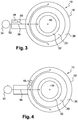
Comme cela est schématiquement représenté en
On se réfère maintenant à la
Selon l'invention, des moyens sont prévus pour alimenter en air la canalisation 36, cet air étant destiné à être acheminé par la canalisation 36 jusqu'aux cavités 26, 32 en vue de leur ventilation.According to the invention, means are provided for supplying air to the
Dans l'exemple représenté, les moyens d'alimentation en air comprennent un ventilateur électrique 48 dont la sortie d'air 50 est reliée à la canalisation 36, au voisinage de son entrée 52 reliée aux moyens d'alimentation 34. Cette liaison peut se faire par une dérivation en Y (de préférence en amont de la paroi anti-feu) dont l'une des branches latérales est reliée au ventilateur 48, l'autre branche latérale est reliée aux moyens d'alimentation 34, et la branche médiane est reliée aux cavités 26, 32. La liaison entre le ventilateur 48 et la canalisation 36 peut comprendre une électrovanne ou un clapet anti-retour.In the example shown, the air supply means comprise an
Le ventilateur 48 peut être configuré pour délivrer un débit d'air compris entre 1 et 500g/s.The
Le ventilateur 48 est de préférence commandé électriquement par des moyens de contrôle indépendants du moteur 16 de façon à ce qu'il puisse fonctionner à l'arrêt moteur. Ces moyens de contrôle sont par exemple intégrés au réseau électronique de l'aéronef.The
Dans l'exemple représenté en
La variante de réalisation de l'invention représentée en
Comme cela est représenté en
Claims (9)
- Aircraft propulsion assembly (10) comprising an engine (16), a nacelle (18) surrounding the engine, and a system for extinguishing a fire which may break out in the engine and/or in the nacelle, this extinguishing system comprising means (34) for supplying extinguishing agent to at least one pipe (36) which is intended for dispensing said extinguishing agent and leads into a cavity (32) in the engine and/or a cavity (26) in the nacelle, characterised in that said propulsion assembly further comprises means (48) for supplying air to said at least one pipe in order to ventilate the cavity/cavities.
- Propulsion assembly (10) according to claim 1, characterised in that the air supply means comprise a ventilator fan (48).
- Propulsion assembly (10) according to claim 2, characterised in that the ventilator fan (48) is an electric ventilator fan.
- Propulsion assembly (10) according to any of the preceding claims, characterised in that the air supply means (48) are connected to said at least one pipe (36) by a valve and/or a non-return flap.
- Propulsion assembly (10) according to any of the preceding claims, characterised in that the air supply means (48) are housed in the nacelle (18).
- Propulsion assembly (10) according to any of claims 1 to 4, characterised in that it further comprises a strut (12) for connecting the propulsion assembly to the aircraft, said air supply means (48) being housed in the strut.
- Propulsion assembly (10) according to any of the preceding claims, characterised in that the air supply means (48) are designed to output an air flow rate of between 1 and 500 g/s.
- Propulsion assembly (10) according to any of the preceding claims, characterised in that the pipe (36) comprises at least one outlet (38, 40) which is located close to an air intake scoop of the nacelle (18) or of the engine (16).
- Method for ventilating a cavity (32, 26) in an engine (16) and/or a cavity in a nacelle (18) of an aircraft propulsion assembly (10), this propulsion assembly comprising a system for extinguishing a fire which may break out in the engine and/or in the nacelle, this extinguishing system comprising means (34) for supplying extinguishing agent to at least one pipe (36) which is intended for dispensing said extinguishing agent and leads into the cavity in the engine and/or the cavity in the nacelle, characterised in that said method comprises supplying air to said at least one pipe.
Applications Claiming Priority (2)
| Application Number | Priority Date | Filing Date | Title |
|---|---|---|---|
| FR1363544A FR3015568B1 (en) | 2013-12-24 | 2013-12-24 | VENTILATION OF A PROPELLANT AIRCRAFT ASSEMBLY |
| PCT/FR2014/053497 WO2015097391A1 (en) | 2013-12-24 | 2014-12-22 | Aircraft propulsion assembly with fire extinguishing system |
Publications (2)
| Publication Number | Publication Date |
|---|---|
| EP3087265A1 EP3087265A1 (en) | 2016-11-02 |
| EP3087265B1 true EP3087265B1 (en) | 2018-02-07 |
Family
ID=50137945
Family Applications (1)
| Application Number | Title | Priority Date | Filing Date |
|---|---|---|---|
| EP14833513.6A Active EP3087265B1 (en) | 2013-12-24 | 2014-12-22 | Aircraft propulsion assembly with fire extinguishing system and ventilation method |
Country Status (7)
| Country | Link |
|---|---|
| US (1) | US10336464B2 (en) |
| EP (1) | EP3087265B1 (en) |
| CN (1) | CN105793542B (en) |
| CA (1) | CA2929951C (en) |
| FR (1) | FR3015568B1 (en) |
| RU (1) | RU2672197C2 (en) |
| WO (1) | WO2015097391A1 (en) |
Cited By (1)
| Publication number | Priority date | Publication date | Assignee | Title |
|---|---|---|---|---|
| DE102018222162A1 (en) * | 2018-12-18 | 2020-06-18 | Rolls-Royce Deutschland Ltd & Co Kg | Ventilation and extinguishing device for a gas turbine engine |
Families Citing this family (10)
| Publication number | Priority date | Publication date | Assignee | Title |
|---|---|---|---|---|
| FR3039591B1 (en) * | 2015-07-31 | 2017-08-25 | Snecma | INSULATION OF AN AIRCRAFT TURBOMACHINE TANK IN THE EVENT OF FIRE BY CLOSURE OF A VALVE SENSITIVE TO THE RELEASE OF AN EXTINGUISHING AGENT |
| FR3041936B1 (en) | 2015-10-02 | 2018-08-17 | Airbus Operations | PROPULSIVE AIRCRAFT SYSTEM COMPRISING AT LEAST ONE FIRE RESISTANT |
| US10369393B2 (en) * | 2017-11-01 | 2019-08-06 | The Boeing Company | Aircraft fire extinguishing with heated tubing |
| EP3703827A4 (en) * | 2017-11-03 | 2021-08-11 | Bombardier Inc. | Aircraft fire suppression system |
| FR3081514B1 (en) * | 2018-05-28 | 2020-06-05 | Safran Aircraft Engines | AIRCRAFT POWDER ASSEMBLY AND METHOD FOR REDUCING VENTILATION AIR FLOW IN THE AIRCRAFT POWDER ASSEMBLY |
| US11230975B2 (en) | 2019-03-20 | 2022-01-25 | Raytheon Technologies Corporation | Modulated fire extinguishing vent for a gas turbine engine |
| CN111997760B (en) * | 2019-05-27 | 2022-01-21 | 中国航发商用航空发动机有限责任公司 | Aircraft engine |
| FR3110141A1 (en) * | 2020-05-13 | 2021-11-19 | Airbus Operations (S.A.S.) | Aircraft comprising a propulsion unit and a propulsion unit fire-fighting system. |
| FR3112121A1 (en) | 2020-07-02 | 2022-01-07 | Airbus Operations (S.A.S.) | AIRCRAFT PROPELLER ASSEMBLY INCLUDING A FIRE-FIGHTING SYSTEM WITH A DISTRIBUTION LINE OF EXTINGUISHING AGENT. |
| EP4223986A1 (en) * | 2022-02-07 | 2023-08-09 | Rolls-Royce Deutschland Ltd & Co KG | Turbine generator system |
Family Cites Families (12)
| Publication number | Priority date | Publication date | Assignee | Title |
|---|---|---|---|---|
| US4304093A (en) * | 1979-08-31 | 1981-12-08 | General Electric Company | Variable clearance control for a gas turbine engine |
| US4351394A (en) * | 1979-12-28 | 1982-09-28 | Enk William A | Method and system for aircraft fire protection |
| US4441314A (en) * | 1980-09-26 | 1984-04-10 | United Technologies Corporation | Combined turbine power plant blade tip clearance and nacelle ventilation system |
| JPS61132728A (en) * | 1984-12-03 | 1986-06-20 | Hitachi Ltd | Internal ventilation equipment of gas turbine package |
| US5239817A (en) * | 1991-11-04 | 1993-08-31 | General Electric Company | Fire zone ventilation shut-off system |
| US6082464A (en) * | 1997-07-22 | 2000-07-04 | Primex Technologies, Inc. | Dual stage fire extinguisher |
| US6935433B2 (en) * | 2002-07-31 | 2005-08-30 | The Boeing Company | Helium gas total flood fire suppression system |
| AU2006204755B2 (en) * | 2005-01-12 | 2012-01-12 | Eclipse Aerospace, Inc. | Fire suppression systems |
| RU2324064C1 (en) * | 2006-08-14 | 2008-05-10 | Николай Борисович Болотин | Energy gas-turbine power plant |
| FR2905358B1 (en) * | 2006-09-06 | 2008-10-17 | Eurocopter France | FIREWALL FLAME OF AIRCRAFT. |
| FR2960912B1 (en) | 2010-06-08 | 2012-06-08 | Snecma | DEVICE FOR PROTECTING AN AIRCRAFT TURBO-MACHINE CALCULATOR IN CASES OF FIRE |
| DE102012002131B4 (en) * | 2012-02-03 | 2021-07-29 | Airbus Operations Gmbh | Emergency supply system for a means of transport, method for providing electrical power and for suppressing fire and means of transport with an emergency supply system |
-
2013
- 2013-12-24 FR FR1363544A patent/FR3015568B1/en active Active
-
2014
- 2014-12-22 WO PCT/FR2014/053497 patent/WO2015097391A1/en active Application Filing
- 2014-12-22 EP EP14833513.6A patent/EP3087265B1/en active Active
- 2014-12-22 US US15/100,246 patent/US10336464B2/en active Active
- 2014-12-22 CN CN201480065639.6A patent/CN105793542B/en active Active
- 2014-12-22 CA CA2929951A patent/CA2929951C/en active Active
- 2014-12-22 RU RU2016121154A patent/RU2672197C2/en active
Cited By (1)
| Publication number | Priority date | Publication date | Assignee | Title |
|---|---|---|---|---|
| DE102018222162A1 (en) * | 2018-12-18 | 2020-06-18 | Rolls-Royce Deutschland Ltd & Co Kg | Ventilation and extinguishing device for a gas turbine engine |
Also Published As
| Publication number | Publication date |
|---|---|
| FR3015568A1 (en) | 2015-06-26 |
| CN105793542A (en) | 2016-07-20 |
| CA2929951A1 (en) | 2015-07-02 |
| CN105793542B (en) | 2017-11-28 |
| RU2672197C2 (en) | 2018-11-12 |
| RU2016121154A (en) | 2018-01-30 |
| EP3087265A1 (en) | 2016-11-02 |
| US20160368618A1 (en) | 2016-12-22 |
| RU2016121154A3 (en) | 2018-09-27 |
| CA2929951C (en) | 2022-03-08 |
| US10336464B2 (en) | 2019-07-02 |
| FR3015568B1 (en) | 2016-01-01 |
| WO2015097391A1 (en) | 2015-07-02 |
Similar Documents
| Publication | Publication Date | Title |
|---|---|---|
| EP3087265B1 (en) | Aircraft propulsion assembly with fire extinguishing system and ventilation method | |
| EP3013689B1 (en) | De-icing and conditioning device for an aircraft | |
| CA2581540A1 (en) | Turbine engine inlet cone deicing system for aircraft | |
| CA2933531C (en) | Fluid-draining device for an aircraft engine | |
| EP2979980B1 (en) | Method and device for detecting when an aircraft flies in icing conditions | |
| WO2015092251A1 (en) | Aircraft turbomachine comprising a heat exchanger of the precooler type | |
| CA2925565C (en) | Turbomachine combustion chamber provided with air deflection means for reducing the wake created by an ignition plug | |
| EP3698022B1 (en) | Turbomachine and method of cooling a low pressure turbine of a turbomachine | |
| FR3039213A1 (en) | TURBOMACHINE COMPRISING AT LEAST TWO GENERATORS OF GAS AND VARIABLE FLOW DISTRIBUTION IN THE POWER TURBINE | |
| CA2875044A1 (en) | Casing for a propulsion assembly | |
| CA2193167A1 (en) | System for engine restart following complete inflight engine shutdown | |
| FR3075875B1 (en) | OIL CIRCUIT FOR AUXILIARY OIL RING TURBOMACHINE | |
| EP2941382B1 (en) | Electric de-icing device for turbojet engine nacelle | |
| FR3084446A1 (en) | MONOBLOCK COMBUSTION CHAMBER | |
| FR2960912A1 (en) | Controller protecting device for turbomachine of aircraft, has lid covering main case and comprising air inlet zone and air outlet zone, and air circulation system assuring circulation of air between air inlet and air outlet zones | |
| FR3081514A1 (en) | PROPELLANT AIRCRAFT ASSEMBLY AND METHOD FOR REDUCING VENTILATION AIR FLOW IN THE AIRCRAFT PROPELLANT ASSEMBLY | |
| EP2643069B1 (en) | Oil discharge device and turbomachine comprising such a device | |
| EP2697493B1 (en) | Fuel pipes with means for controlling a pump | |
| EP3126232B1 (en) | Drive chain for a helicopter incorporating a pyrotechnic assistance drive module and helicopter comprising same | |
| WO2015118274A1 (en) | System for the emergency starting of a turbomachine | |
| FR3070418A1 (en) | AIRCRAFT TURBOMACHINE | |
| EP3041742B1 (en) | Engine casing having pivotable access doors | |
| FR3044865A1 (en) | ELECTRONIC CALCULATOR OF AN AIRCRAFT TURBOMACHINE | |
| FR3005486A1 (en) | LUBRICATION IN A TURBOMACHINE | |
| WO2023118745A1 (en) | Integrating an extinguisher into a "fire" zone of a turbomachine |
Legal Events
| Date | Code | Title | Description |
|---|---|---|---|
| PUAI | Public reference made under article 153(3) epc to a published international application that has entered the european phase |
Free format text: ORIGINAL CODE: 0009012 |
|
| 17P | Request for examination filed |
Effective date: 20160519 |
|
| AK | Designated contracting states |
Kind code of ref document: A1 Designated state(s): AL AT BE BG CH CY CZ DE DK EE ES FI FR GB GR HR HU IE IS IT LI LT LU LV MC MK MT NL NO PL PT RO RS SE SI SK SM TR |
|
| AX | Request for extension of the european patent |
Extension state: BA ME |
|
| DAX | Request for extension of the european patent (deleted) | ||
| GRAP | Despatch of communication of intention to grant a patent |
Free format text: ORIGINAL CODE: EPIDOSNIGR1 |
|
| INTG | Intention to grant announced |
Effective date: 20170906 |
|
| GRAS | Grant fee paid |
Free format text: ORIGINAL CODE: EPIDOSNIGR3 |
|
| GRAA | (expected) grant |
Free format text: ORIGINAL CODE: 0009210 |
|
| AK | Designated contracting states |
Kind code of ref document: B1 Designated state(s): AL AT BE BG CH CY CZ DE DK EE ES FI FR GB GR HR HU IE IS IT LI LT LU LV MC MK MT NL NO PL PT RO RS SE SI SK SM TR |
|
| REG | Reference to a national code |
Ref country code: GB Ref legal event code: FG4D Free format text: NOT ENGLISH |
|
| REG | Reference to a national code |
Ref country code: AT Ref legal event code: REF Ref document number: 968910 Country of ref document: AT Kind code of ref document: T Effective date: 20180215 Ref country code: CH Ref legal event code: EP |
|
| REG | Reference to a national code |
Ref country code: IE Ref legal event code: FG4D Free format text: LANGUAGE OF EP DOCUMENT: FRENCH |
|
| REG | Reference to a national code |
Ref country code: DE Ref legal event code: R096 Ref document number: 602014020833 Country of ref document: DE |
|
| REG | Reference to a national code |
Ref country code: SE Ref legal event code: TRGR |
|
| REG | Reference to a national code |
Ref country code: NL Ref legal event code: MP Effective date: 20180207 |
|
| REG | Reference to a national code |
Ref country code: AT Ref legal event code: MK05 Ref document number: 968910 Country of ref document: AT Kind code of ref document: T Effective date: 20180207 |
|
| PG25 | Lapsed in a contracting state [announced via postgrant information from national office to epo] |
Ref country code: NL Free format text: LAPSE BECAUSE OF FAILURE TO SUBMIT A TRANSLATION OF THE DESCRIPTION OR TO PAY THE FEE WITHIN THE PRESCRIBED TIME-LIMIT Effective date: 20180207 Ref country code: LT Free format text: LAPSE BECAUSE OF FAILURE TO SUBMIT A TRANSLATION OF THE DESCRIPTION OR TO PAY THE FEE WITHIN THE PRESCRIBED TIME-LIMIT Effective date: 20180207 Ref country code: ES Free format text: LAPSE BECAUSE OF FAILURE TO SUBMIT A TRANSLATION OF THE DESCRIPTION OR TO PAY THE FEE WITHIN THE PRESCRIBED TIME-LIMIT Effective date: 20180207 Ref country code: CY Free format text: LAPSE BECAUSE OF FAILURE TO SUBMIT A TRANSLATION OF THE DESCRIPTION OR TO PAY THE FEE WITHIN THE PRESCRIBED TIME-LIMIT Effective date: 20180207 Ref country code: FI Free format text: LAPSE BECAUSE OF FAILURE TO SUBMIT A TRANSLATION OF THE DESCRIPTION OR TO PAY THE FEE WITHIN THE PRESCRIBED TIME-LIMIT Effective date: 20180207 Ref country code: HR Free format text: LAPSE BECAUSE OF FAILURE TO SUBMIT A TRANSLATION OF THE DESCRIPTION OR TO PAY THE FEE WITHIN THE PRESCRIBED TIME-LIMIT Effective date: 20180207 Ref country code: NO Free format text: LAPSE BECAUSE OF FAILURE TO SUBMIT A TRANSLATION OF THE DESCRIPTION OR TO PAY THE FEE WITHIN THE PRESCRIBED TIME-LIMIT Effective date: 20180507 |
|
| PG25 | Lapsed in a contracting state [announced via postgrant information from national office to epo] |
Ref country code: LV Free format text: LAPSE BECAUSE OF FAILURE TO SUBMIT A TRANSLATION OF THE DESCRIPTION OR TO PAY THE FEE WITHIN THE PRESCRIBED TIME-LIMIT Effective date: 20180207 Ref country code: RS Free format text: LAPSE BECAUSE OF FAILURE TO SUBMIT A TRANSLATION OF THE DESCRIPTION OR TO PAY THE FEE WITHIN THE PRESCRIBED TIME-LIMIT Effective date: 20180207 Ref country code: AT Free format text: LAPSE BECAUSE OF FAILURE TO SUBMIT A TRANSLATION OF THE DESCRIPTION OR TO PAY THE FEE WITHIN THE PRESCRIBED TIME-LIMIT Effective date: 20180207 Ref country code: BG Free format text: LAPSE BECAUSE OF FAILURE TO SUBMIT A TRANSLATION OF THE DESCRIPTION OR TO PAY THE FEE WITHIN THE PRESCRIBED TIME-LIMIT Effective date: 20180507 Ref country code: PL Free format text: LAPSE BECAUSE OF FAILURE TO SUBMIT A TRANSLATION OF THE DESCRIPTION OR TO PAY THE FEE WITHIN THE PRESCRIBED TIME-LIMIT Effective date: 20180207 Ref country code: GR Free format text: LAPSE BECAUSE OF FAILURE TO SUBMIT A TRANSLATION OF THE DESCRIPTION OR TO PAY THE FEE WITHIN THE PRESCRIBED TIME-LIMIT Effective date: 20180508 Ref country code: IS Free format text: LAPSE BECAUSE OF FAILURE TO SUBMIT A TRANSLATION OF THE DESCRIPTION OR TO PAY THE FEE WITHIN THE PRESCRIBED TIME-LIMIT Effective date: 20180607 |
|
| PG25 | Lapsed in a contracting state [announced via postgrant information from national office to epo] |
Ref country code: MT Free format text: LAPSE BECAUSE OF FAILURE TO SUBMIT A TRANSLATION OF THE DESCRIPTION OR TO PAY THE FEE WITHIN THE PRESCRIBED TIME-LIMIT Effective date: 20180207 |
|
| PG25 | Lapsed in a contracting state [announced via postgrant information from national office to epo] |
Ref country code: AL Free format text: LAPSE BECAUSE OF FAILURE TO SUBMIT A TRANSLATION OF THE DESCRIPTION OR TO PAY THE FEE WITHIN THE PRESCRIBED TIME-LIMIT Effective date: 20180207 Ref country code: RO Free format text: LAPSE BECAUSE OF FAILURE TO SUBMIT A TRANSLATION OF THE DESCRIPTION OR TO PAY THE FEE WITHIN THE PRESCRIBED TIME-LIMIT Effective date: 20180207 Ref country code: EE Free format text: LAPSE BECAUSE OF FAILURE TO SUBMIT A TRANSLATION OF THE DESCRIPTION OR TO PAY THE FEE WITHIN THE PRESCRIBED TIME-LIMIT Effective date: 20180207 |
|
| REG | Reference to a national code |
Ref country code: DE Ref legal event code: R097 Ref document number: 602014020833 Country of ref document: DE |
|
| PG25 | Lapsed in a contracting state [announced via postgrant information from national office to epo] |
Ref country code: SM Free format text: LAPSE BECAUSE OF FAILURE TO SUBMIT A TRANSLATION OF THE DESCRIPTION OR TO PAY THE FEE WITHIN THE PRESCRIBED TIME-LIMIT Effective date: 20180207 Ref country code: SK Free format text: LAPSE BECAUSE OF FAILURE TO SUBMIT A TRANSLATION OF THE DESCRIPTION OR TO PAY THE FEE WITHIN THE PRESCRIBED TIME-LIMIT Effective date: 20180207 Ref country code: DK Free format text: LAPSE BECAUSE OF FAILURE TO SUBMIT A TRANSLATION OF THE DESCRIPTION OR TO PAY THE FEE WITHIN THE PRESCRIBED TIME-LIMIT Effective date: 20180207 Ref country code: CZ Free format text: LAPSE BECAUSE OF FAILURE TO SUBMIT A TRANSLATION OF THE DESCRIPTION OR TO PAY THE FEE WITHIN THE PRESCRIBED TIME-LIMIT Effective date: 20180207 |
|
| PLBE | No opposition filed within time limit |
Free format text: ORIGINAL CODE: 0009261 |
|
| STAA | Information on the status of an ep patent application or granted ep patent |
Free format text: STATUS: NO OPPOSITION FILED WITHIN TIME LIMIT |
|
| 26N | No opposition filed |
Effective date: 20181108 |
|
| PG25 | Lapsed in a contracting state [announced via postgrant information from national office to epo] |
Ref country code: SI Free format text: LAPSE BECAUSE OF FAILURE TO SUBMIT A TRANSLATION OF THE DESCRIPTION OR TO PAY THE FEE WITHIN THE PRESCRIBED TIME-LIMIT Effective date: 20180207 |
|
| REG | Reference to a national code |
Ref country code: CH Ref legal event code: PL |
|
| PG25 | Lapsed in a contracting state [announced via postgrant information from national office to epo] |
Ref country code: MC Free format text: LAPSE BECAUSE OF FAILURE TO SUBMIT A TRANSLATION OF THE DESCRIPTION OR TO PAY THE FEE WITHIN THE PRESCRIBED TIME-LIMIT Effective date: 20180207 Ref country code: LU Free format text: LAPSE BECAUSE OF NON-PAYMENT OF DUE FEES Effective date: 20181222 |
|
| REG | Reference to a national code |
Ref country code: IE Ref legal event code: MM4A |
|
| REG | Reference to a national code |
Ref country code: BE Ref legal event code: MM Effective date: 20181231 |
|
| PG25 | Lapsed in a contracting state [announced via postgrant information from national office to epo] |
Ref country code: IE Free format text: LAPSE BECAUSE OF NON-PAYMENT OF DUE FEES Effective date: 20181222 |
|
| PG25 | Lapsed in a contracting state [announced via postgrant information from national office to epo] |
Ref country code: BE Free format text: LAPSE BECAUSE OF NON-PAYMENT OF DUE FEES Effective date: 20181231 |
|
| PG25 | Lapsed in a contracting state [announced via postgrant information from national office to epo] |
Ref country code: LI Free format text: LAPSE BECAUSE OF NON-PAYMENT OF DUE FEES Effective date: 20181231 Ref country code: CH Free format text: LAPSE BECAUSE OF NON-PAYMENT OF DUE FEES Effective date: 20181231 |
|
| PG25 | Lapsed in a contracting state [announced via postgrant information from national office to epo] |
Ref country code: TR Free format text: LAPSE BECAUSE OF FAILURE TO SUBMIT A TRANSLATION OF THE DESCRIPTION OR TO PAY THE FEE WITHIN THE PRESCRIBED TIME-LIMIT Effective date: 20180207 |
|
| PG25 | Lapsed in a contracting state [announced via postgrant information from national office to epo] |
Ref country code: PT Free format text: LAPSE BECAUSE OF FAILURE TO SUBMIT A TRANSLATION OF THE DESCRIPTION OR TO PAY THE FEE WITHIN THE PRESCRIBED TIME-LIMIT Effective date: 20180207 |
|
| PG25 | Lapsed in a contracting state [announced via postgrant information from national office to epo] |
Ref country code: HU Free format text: LAPSE BECAUSE OF FAILURE TO SUBMIT A TRANSLATION OF THE DESCRIPTION OR TO PAY THE FEE WITHIN THE PRESCRIBED TIME-LIMIT; INVALID AB INITIO Effective date: 20141222 Ref country code: MK Free format text: LAPSE BECAUSE OF NON-PAYMENT OF DUE FEES Effective date: 20180207 |
|
| PGFP | Annual fee paid to national office [announced via postgrant information from national office to epo] |
Ref country code: IT Payment date: 20221122 Year of fee payment: 9 |
|
| PGFP | Annual fee paid to national office [announced via postgrant information from national office to epo] |
Ref country code: GB Payment date: 20231121 Year of fee payment: 10 |
|
| PGFP | Annual fee paid to national office [announced via postgrant information from national office to epo] |
Ref country code: SE Payment date: 20231121 Year of fee payment: 10 Ref country code: FR Payment date: 20231122 Year of fee payment: 10 Ref country code: DE Payment date: 20231121 Year of fee payment: 10 |