EP3086988B1 - Spring brake cylinder with emergency release device - Google Patents
Spring brake cylinder with emergency release device Download PDFInfo
- Publication number
- EP3086988B1 EP3086988B1 EP14824835.4A EP14824835A EP3086988B1 EP 3086988 B1 EP3086988 B1 EP 3086988B1 EP 14824835 A EP14824835 A EP 14824835A EP 3086988 B1 EP3086988 B1 EP 3086988B1
- Authority
- EP
- European Patent Office
- Prior art keywords
- spring brake
- brake cylinder
- spring
- brake piston
- piston tube
- Prior art date
- Legal status (The legal status is an assumption and is not a legal conclusion. Google has not performed a legal analysis and makes no representation as to the accuracy of the status listed.)
- Active
Links
- 230000000295 complement effect Effects 0.000 claims description 10
- 230000004323 axial length Effects 0.000 claims description 7
- 239000004952 Polyamide Substances 0.000 claims description 5
- 229920002647 polyamide Polymers 0.000 claims description 5
- 230000009471 action Effects 0.000 claims description 2
- 239000011521 glass Substances 0.000 claims 1
- 230000002093 peripheral effect Effects 0.000 description 7
- 239000012528 membrane Substances 0.000 description 5
- 238000013022 venting Methods 0.000 description 5
- 238000006073 displacement reaction Methods 0.000 description 4
- 239000000463 material Substances 0.000 description 4
- 230000007246 mechanism Effects 0.000 description 3
- 239000004033 plastic Substances 0.000 description 3
- 229910052782 aluminium Inorganic materials 0.000 description 2
- XAGFODPZIPBFFR-UHFFFAOYSA-N aluminium Chemical compound [Al] XAGFODPZIPBFFR-UHFFFAOYSA-N 0.000 description 2
- 230000000694 effects Effects 0.000 description 2
- 240000000731 Fagus sylvatica Species 0.000 description 1
- 235000010099 Fagus sylvatica Nutrition 0.000 description 1
- 238000005299 abrasion Methods 0.000 description 1
- 230000015556 catabolic process Effects 0.000 description 1
- 230000008859 change Effects 0.000 description 1
- 238000004891 communication Methods 0.000 description 1
- 230000001934 delay Effects 0.000 description 1
- 230000001419 dependent effect Effects 0.000 description 1
- 230000018109 developmental process Effects 0.000 description 1
- 238000005553 drilling Methods 0.000 description 1
- 239000003365 glass fiber Substances 0.000 description 1
- 238000002347 injection Methods 0.000 description 1
- 239000007924 injection Substances 0.000 description 1
- 238000009434 installation Methods 0.000 description 1
- 229910052751 metal Inorganic materials 0.000 description 1
- 239000002184 metal Substances 0.000 description 1
- 238000005192 partition Methods 0.000 description 1
- 230000008092 positive effect Effects 0.000 description 1
- 230000009467 reduction Effects 0.000 description 1
- 238000005096 rolling process Methods 0.000 description 1
- 238000007789 sealing Methods 0.000 description 1
- 239000000243 solution Substances 0.000 description 1
Images

Classifications
-
- B—PERFORMING OPERATIONS; TRANSPORTING
- B60—VEHICLES IN GENERAL
- B60T—VEHICLE BRAKE CONTROL SYSTEMS OR PARTS THEREOF; BRAKE CONTROL SYSTEMS OR PARTS THEREOF, IN GENERAL; ARRANGEMENT OF BRAKING ELEMENTS ON VEHICLES IN GENERAL; PORTABLE DEVICES FOR PREVENTING UNWANTED MOVEMENT OF VEHICLES; VEHICLE MODIFICATIONS TO FACILITATE COOLING OF BRAKES
- B60T17/00—Component parts, details, or accessories of power brake systems not covered by groups B60T8/00, B60T13/00 or B60T15/00, or presenting other characteristic features
- B60T17/08—Brake cylinders other than ultimate actuators
- B60T17/085—Spring loaded brake actuators
- B60T17/086—Spring loaded brake actuators with emergency release device
-
- B—PERFORMING OPERATIONS; TRANSPORTING
- B60—VEHICLES IN GENERAL
- B60T—VEHICLE BRAKE CONTROL SYSTEMS OR PARTS THEREOF; BRAKE CONTROL SYSTEMS OR PARTS THEREOF, IN GENERAL; ARRANGEMENT OF BRAKING ELEMENTS ON VEHICLES IN GENERAL; PORTABLE DEVICES FOR PREVENTING UNWANTED MOVEMENT OF VEHICLES; VEHICLE MODIFICATIONS TO FACILITATE COOLING OF BRAKES
- B60T17/00—Component parts, details, or accessories of power brake systems not covered by groups B60T8/00, B60T13/00 or B60T15/00, or presenting other characteristic features
- B60T17/08—Brake cylinders other than ultimate actuators
- B60T17/083—Combination of service brake actuators with spring loaded brake actuators
-
- F—MECHANICAL ENGINEERING; LIGHTING; HEATING; WEAPONS; BLASTING
- F16—ENGINEERING ELEMENTS AND UNITS; GENERAL MEASURES FOR PRODUCING AND MAINTAINING EFFECTIVE FUNCTIONING OF MACHINES OR INSTALLATIONS; THERMAL INSULATION IN GENERAL
- F16D—COUPLINGS FOR TRANSMITTING ROTATION; CLUTCHES; BRAKES
- F16D65/00—Parts or details
- F16D65/14—Actuating mechanisms for brakes; Means for initiating operation at a predetermined position
- F16D65/28—Actuating mechanisms for brakes; Means for initiating operation at a predetermined position arranged apart from the brake
-
- B—PERFORMING OPERATIONS; TRANSPORTING
- B60—VEHICLES IN GENERAL
- B60T—VEHICLE BRAKE CONTROL SYSTEMS OR PARTS THEREOF; BRAKE CONTROL SYSTEMS OR PARTS THEREOF, IN GENERAL; ARRANGEMENT OF BRAKING ELEMENTS ON VEHICLES IN GENERAL; PORTABLE DEVICES FOR PREVENTING UNWANTED MOVEMENT OF VEHICLES; VEHICLE MODIFICATIONS TO FACILITATE COOLING OF BRAKES
- B60T2270/00—Further aspects of brake control systems not otherwise provided for
- B60T2270/40—Failsafe aspects of brake control systems
- B60T2270/403—Brake circuit failure
-
- F—MECHANICAL ENGINEERING; LIGHTING; HEATING; WEAPONS; BLASTING
- F16—ENGINEERING ELEMENTS AND UNITS; GENERAL MEASURES FOR PRODUCING AND MAINTAINING EFFECTIVE FUNCTIONING OF MACHINES OR INSTALLATIONS; THERMAL INSULATION IN GENERAL
- F16D—COUPLINGS FOR TRANSMITTING ROTATION; CLUTCHES; BRAKES
- F16D2121/00—Type of actuator operation force
- F16D2121/02—Fluid pressure
- F16D2121/12—Fluid pressure for releasing a normally applied brake, the type of actuator being irrelevant or not provided for in groups F16D2121/04 - F16D2121/10
-
- F—MECHANICAL ENGINEERING; LIGHTING; HEATING; WEAPONS; BLASTING
- F16—ENGINEERING ELEMENTS AND UNITS; GENERAL MEASURES FOR PRODUCING AND MAINTAINING EFFECTIVE FUNCTIONING OF MACHINES OR INSTALLATIONS; THERMAL INSULATION IN GENERAL
- F16D—COUPLINGS FOR TRANSMITTING ROTATION; CLUTCHES; BRAKES
- F16D2123/00—Multiple operation forces
-
- F—MECHANICAL ENGINEERING; LIGHTING; HEATING; WEAPONS; BLASTING
- F16—ENGINEERING ELEMENTS AND UNITS; GENERAL MEASURES FOR PRODUCING AND MAINTAINING EFFECTIVE FUNCTIONING OF MACHINES OR INSTALLATIONS; THERMAL INSULATION IN GENERAL
- F16D—COUPLINGS FOR TRANSMITTING ROTATION; CLUTCHES; BRAKES
- F16D2125/00—Components of actuators
- F16D2125/02—Fluid-pressure mechanisms
- F16D2125/06—Pistons
-
- F—MECHANICAL ENGINEERING; LIGHTING; HEATING; WEAPONS; BLASTING
- F16—ENGINEERING ELEMENTS AND UNITS; GENERAL MEASURES FOR PRODUCING AND MAINTAINING EFFECTIVE FUNCTIONING OF MACHINES OR INSTALLATIONS; THERMAL INSULATION IN GENERAL
- F16D—COUPLINGS FOR TRANSMITTING ROTATION; CLUTCHES; BRAKES
- F16D2127/00—Auxiliary mechanisms
- F16D2127/02—Release mechanisms
- F16D2127/04—Release mechanisms for manual operation
Definitions
- the invention relates to a pneumatic spring brake cylinder for brake systems of vehicles, according to the preamble of claim 1.
- a generic pneumatic spring brake cylinder is off WO 02/44004 A1 known.
- Such a spring brake cylinder usually has a housing in which a spring brake piston is guided, which divides the interior of the housing into a spring-loaded chamber and a pressure chamber.
- a spring device is arranged, which biases the spring brake piston in the direction of the pressure chamber. So that a parked or braked vehicle, in which the spring brake cylinder is arranged, can be moved, the pressure chamber is so pressurized with compressed air, that the spring brake piston is moved against the biasing effect of the storage spring.
- a braking device coupled to the spring brake piston comes out of engagement with a brake disk, so that the vehicle is not braked further.
- such a spring brake cylinder can be coupled in a known manner with a service brake cylinder in the form of a so-called. Combi cylinder.
- the spring brake piston actuates in the parking brake case with its spring brake piston tube a service brake piston of the service brake cylinder, which in turn has a service brake piston rod which cooperates with a brake mechanism of the vehicle brake, in particular a disc brake.
- a brake mechanism is for example in the EP 0 740 085 B1 described and has a pivotally connected to the service brake piston rod pivot lever which is rotatably connected to a Zuspannwelle, which is provided with a cam contour which upon rotation of the Zuspannwelle about its longitudinal axis to an axial Relative movement of a caliper and a brake shoe of a disc brake leads.
- the spring brake piston is displaced in the direction of the pressure chamber due to the prestressing of the accumulator spring in such a way that the braking device coupled to the spring brake piston engages and carries out a braking of the vehicle. This is to be reliably prevented for example in a line breakage of the brake pressure line while driving that a commercial vehicle continues unrestrained and thus difficult to control.
- This emergency braking in the absence of compressed air supply is also used in over long periods parked trailers, etc., so that unintentional rolling away of these vehicles can be prevented.
- the braking effect thus exerted by the mechanical accumulator spring in the spring brake cylinder in such cases should be able to be released, for example, for moving stowed vehicles or clearing a lane blocked due to a breakdown, so that the vehicles concerned are moved and e.g. Traffic delays can be lifted.
- the outwardly facing end of the spring brake piston tube is provided with an inwardly projecting flange which acts as a stop for the nut. Due to the introduced by the rotational movement of the threaded spindle linear displacement screwed onto the nut threaded spindle in the axial direction, the mother proposes to the flange of the spring brake piston tube, which is due to further rotation of the threaded spindle to a linear displacement of the spring accumulator piston against the biasing force of the accumulator spring, so that As a result, the cooperating with the spring accumulator piston braking device can be released.
- the nut is rotatably held by a positive connection in the spring brake piston tube, wherein on the outer circumference of the nut in the circumferential circumferential outer polygon profile, in particular a hexagonal profile and a complementarily shaped hexagonal profile on the inner circumference of the spring brake piston tube positively cooperates.
- Emergency release devices are also in CN 102 410 322 A .
- the present invention is based on the object to further develop a spring brake cylinder of the type mentioned in such a way that the disadvantages described above are avoided.
- the invention provides that the positive connection on the one hand between an outer peripheral edge of the nut circumferential polygonal profile and a complementarily formed circumferential polygon profiled section on the inner circumference of an intermediate bushing and on the other by circumferential on the outer circumference of the intermediate bush in the circumferential direction outside polygonal profile and a complementarily formed circumferential polygonal profile is formed on the inner circumference of the spring brake piston tube.
- a polygonal profile should be understood to mean an outer or inner profile which, viewed in cross-section, has a plurality of corners or edges which are connected to one another by any surfaces, in particular straight, convex or concave surfaces.
- the material of the intermediate bush can be selected such that the wear due to a relative sliding movement of the spring brake piston tube relative to the nut is reduced.
- the intermediate bush made of polyamide, in particular glass fiber reinforced polyamide, which has good sliding properties and high rigidity and strength because of the relatively high torsional and shear load, which is initiated by the rotatably held nut.
- the intermediate sleeve could also consist of a metal.
- the materials of the spring brake piston tube or the spring brake piston and / or the mother can be independently selected to other requirements such as stiffness or weight
- the positive connection between the nut and the spring brake piston tube by means of two polygonal profiles allows an extremely space-saving arrangement, because such polygonal profiles, especially with a larger number of edges, envelop substantially a cylindrical circumference and thereby extend only slightly in the radial direction. As a result, the wall thickness of the spring brake piston tube can be comparatively small.
- the threaded spindle on an external thread which cooperates with an internal thread of a formed in a bottom of the housing through hole to screw the threaded spindle in the housing and unscrew.
- the threaded spindle on an external thread which cooperates with an internal thread of a formed in a bottom of the housing through hole to screw the threaded spindle in the housing and unscrew.
- the threaded spindle on an external thread which cooperates with an internal thread of a formed in a bottom of the housing through hole to screw the threaded spindle in the housing and unscrew.
- the threaded spindle could also be held only rotatable, but axially fixed in the bottom of the housing. Such a solution is mentioned in the above WO 97/07322 A1 described. Then, a rotation of the threaded spindle also causes a screwing of the rotatably held nut and thus their axial movement.
- the outer polygonal profile which surrounds the outer circumference of the intermediate bushing in the peripheral direction and the complementary circumferential polygonal polyhedron profile is formed on the inner circumference of the spring brake piston tube by a twelve-edged profile. Due to the relatively high number of twelve edges, the radial extent of the profile is relatively low, which, as already mentioned above, has a positive effect on the installation space.
- the twelve-edged profile can be made in one piece with the spring-loaded brake piston tube. This is particularly advantageous when the spring brake piston tube is designed in one piece with the spring brake piston and an injection molded article, for. made of plastic or aluminum. Then the twelve-edged profile can be urgeformt together with the spring brake piston / spring brake piston tube.
- the outer polygonal profile surrounding the circumference of the outer circumference of the nut and the complementary polygonal polygonal profile formed on the inner circumference of the intermediate bush can be formed by a hexagonal profile. Then, for example, a commercial nut with external hex profile can be used.
- the intermediate bushing can be held axially fixed in the spring brake piston tube, for example between two axial stops, of which a stop is formed by a shoulder extending radially inwards from an inner wall of the spring brake piston tube and a further stop is formed by a disc fixed in the spring brake piston tube.
- the intermediate bushing has at least one axial length, which corresponds to the maximum relative movement between the nut and the spring brake piston tube, so that the nut is rotatably held in any position or in each screwed state.
- the intermediate bushing has at least one axial length which corresponds to the axial screwing region of the nut on the threaded spindle.
- the outer polygonal profile circulating in the circumferential direction on the outer circumference of the intermediate bushing and the complementary circumferential polygonal profile on the inner circumference of the spring brake piston tube extend essentially over the entire axial length of the intermediate bushing. Then, the torque acting on the intermediate bushing torsion torque or thrust torque can be supported by the mother to a relatively large length.
- the axial stop for the nut is formed by a disc which is held in the spring brake piston tube.
- the axial stop for the nut could be integrally formed directly on the spring brake piston tube, for example, characterized in that on the Feder acknowledgedbremskolbenrohr a from the inner wall radially inwardly extending shoulder is formed, which then forms the axial stop for the mother.
- the invention also relates to a combined service brake and spring brake cylinder for brake systems of vehicles, with one described above Spring brake cylinder according to one of the preceding claims.
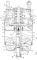
- Fig.1 is a combined service brake and spring brake cylinder 1, hereinafter called combination cylinder shown.
- the combination cylinder 1 consists of a service brake cylinder 2 and a structurally and functionally connected spring brake cylinder 4.
- the service brake cylinder 2 and the spring brake cylinder 4 are separated by an intermediate wall 6 from each other.
- a spring brake piston 8 is slidably disposed, wherein on one side of the spring brake piston 8, a storage spring 10 is present.
- the accumulator spring 10 is supported on its opposite side at the bottom of the spring brake cylinder 4.
- a spring brake chamber 12 is formed, which is in communication with a pressure control module, not shown for reasons of scale, in order to ventilate and vent.
- the spring brake piston 8 is connected to a hollow Feder acknowledgedbremskolbenrohr 18, which extends through the intermediate wall 6 in a service brake chamber 20 of the service brake cylinder 2.
- the spring brake piston 8 may be integrally formed on the spring brake piston tube 18 as shown here, or the spring brake piston 8 and the spring brake piston tube 18 are separate parts that are connected to each other. Also, the spring brake piston 8 itself may be formed in several parts.
- the spring brake piston tube 18 is closed to the service brake cylinder 2 by a bottom which is integral with the spring brake piston tube 18. Is.
- the spring brake piston tube 18 could also be open to the service brake cylinder 2 and the bottom of the Feder acknowledgedbremskolbenrohrs 18 are formed by a cover there placed.
- the service brake chamber 20 opens an inlet, not shown, via which for actuating the service brake cylinder 2 compressed air is admitted and discharged.
- the compressed air acts on a diaphragm 24 inserted within the service brake cylinder 2, on whose opposite side a pressure piece in the form of a stiff diaphragm plate 26 is provided. More specifically, the diaphragm 24 separates the pressure-relieving and releasable service brake chamber 20 of the service brake cylinder 2 from a spring chamber 31 accommodating a return spring 30 supported on the diaphragm plate 26.
- the diaphragm plate 26 is connected to a push rod 28 which cooperates with a brake actuating mechanism outside of the combination cylinder 1.
- a brake actuating mechanism outside of the combination cylinder 1.
- This may be, for example, actuators of a disc brake of a motor vehicle.
- the service brake cylinder 2 is an active brake cylinder, i. that the service brake is applied by venting the service brake chamber 20 and released by venting.
- the on the one hand on the diaphragm plate 26 and on the other hand at the bottom of the service brake cylinder 2 supporting return spring 30 ensures that the push rod 28 is retrieved at vented service brake chamber 20 in the release position.
- a radially outer fastening edge 32 of the membrane 24 has a wedge-shaped, tapering radially inward cross-section.
- This radially outer fastening edge 32 of the membrane 24 with the wedge-shaped, radially inwardly tapering cross section is clamped in a complementarily shaped receptacle 34 with wedge-shaped, radially outwardly flared cross section between the intermediate wall 6 and the service brake cylinder 2.
- the intermediate wall 6 and the service brake cylinder 2 form their outer edges as radially outwardly bent flanges 36, 38, whose mutually facing inner surfaces form the receptacle 34 with a wedge-shaped cross section between them.
- centering ring 40 is arranged substantially perpendicular to a center plane of the fastening edge 32 and protrudes, for example, on one side away from the membrane 24. It is also conceivable, however, that instead of this one centering ring 40 or additionally another, in the direction of the spring brake cylinder 4 projecting and centering against the radially inner peripheral surface of the centering ring is provided.
- the housing of the service brake cylinder 2 and the spring brake cylinder 4 are made of weight reasons, for example, aluminum, while the intermediate wall 6 is made for example of plastic.
- a threaded spindle 50 of an emergency release device 52 can be screwed via a tool attachment surface 48, for example an external hexagon of a hexagon nut.
- the hex nut 48 is rotatably connected to one end of the threaded spindle 50.
- a ring insert is held in the form of a sleeve 54, the central bore is provided here, for example, with an internal thread, in which a male thread on the outer circumference of the threaded spindle 50 is screwed such that the threaded spindle 50 in the housing the spring brake cylinder 4 into or out of this can be unscrewed.
- the threaded spindle 50 in the socket 54 or in the bottom of the spring brake cylinder housing 4 could also be held only rotatable and unverschraubbar, but axially fixed so that it does not change its axial position with respect to the bushing 54 and the spring brake cylinder housing 4 even during rotation.
- the threaded spindle 50 and the bushing 54 do not coincide acting threads, but means for axially fixed, but rotatable mounting of the threaded spindle 50 relative to the sleeve 54 and against the spring brake cylinder housing 4th
- the spring brake is preferably released by unscrewing the threaded spindle 50 manually.
- a rotary movement is effected via a screwing tool, e.g. in the counterclockwise direction in the rotatably connected to the threaded spindle 50 connected hex nut 48, whereby the accumulator spring 10 of the spring brake is compressed and the spring brake is released.
- the threaded spindle 50 in a spring brake piston tube 18 by positive engagement rotatably held nut 56 is screwed, which cooperates with an axial stop 58 on the spring brake piston 8 and the Feder acknowledgedbremskolbenstange 18 to cause a release movement of the spring brake piston 8 against the action of the accumulator spring 10.
- the stop is formed here, for example, by a fixed in the spring brake piston tube, for example by a snap ring washer 58, against which the nut 56 start and thereby bring the spring brake piston 8 upon further rotation of the threaded spindle 50 in the release position, as in Fig.1 is shown.
- This arrangement is in the embodiment of Fig.1 suitable.
- the axial stop can also be formed by a shoulder projecting inwardly from the inner diameter of the spring brake piston tube 18, integrally formed on the spring brake piston tube 18 is formed.
- the nut 56 is rotatably held in the spring brake piston tube 18 by positive engagement.
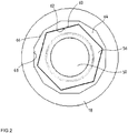
- Fig.2 shows, the positive connection for rotation the nut 56 within the Feder arrivedbremskolbenrohrs 18 on the one hand between a circumferentially circumferential outer polygon on the outer circumference of the nut 56 and a complementarily formed peripheral polygon profiled section 62 on the inner circumference of an intermediate sleeve 64 and on the other by circumferentially around the outer periphery of the intermediate sleeve 64 peripheral polygon profile 66 and a complementary trained circumferential Inner polygonal profile 68 formed on the inner circumference of the spring brake piston tube 18.
- the intermediate bushing 64 is radially interposed between the spring brake piston tube 18 and the nut, at least in the axial screwing region of the nut 56 on the threaded spindle 50.
- the intermediate bushing has at least one axial length which corresponds to the axial screwing region of the nut 56 on the threaded spindle 50.
- the outer polygonal profile 66 which surrounds the outer circumference of the intermediate bush 64 in the circumferential direction and the complementary circumferential polygonal profile 68 formed on the inner circumference of the spring brake piston tube 18 is formed by a twelve-edged profile.
- the twelve-edged profile 68 is designed in one piece with the spring-loaded brake piston tube 18, as is apparent from the detailed illustration of the spring-loaded brake piston 18 Figure 3 evident.
- This perspective view shows the spring brake piston 8 together with the Feder acknowledgedbremskolbenrohr 18 based Fig.1 from the left, ie seen from the bottom of the spring brake cylinder 4 and held there socket 54 from.
- circumferentially circumferential outer polygon profile 60 and the complementarily formed circumferential polygonal profile 62 on the inner circumference of the intermediate bush are formed on the outer circumference of the nut 56, for example by a hexagonal profile
- the intermediate bushing 64 which preferably consists of plastic such as polyamide, is held axially fixed in the spring brake piston tube 18, here for example between the disc 58, which also forms the axial stop for the nut 56 and the venting valve 16 at the bottom of the spring brake piston tube 18.
- Die Eisenbuchse 64 has at least an axial length which is at least as long as the maximum relative movement between the nut 56 and the spring brake piston tube 18 or the axial screw portion of the nut 56 on the threaded spindle 50, so that the nut 56 in each position or in each boblage can be rotatably held on the threaded spindle 50.
Description
Die Erfindung geht aus einem pneumatischen Federspeicherbremszylinder für Bremsanlagen von Fahrzeugen, gemäß dem Oberbegriff von Anspruch 1. Ein gattungsgemäßer pneumatischer Federspeicherbremszylinder ist aus
Ein derartiger Federspeicherbremszylinder weist üblicherweise ein Gehäuse auf, in welchem ein Federspeicherbremskolben geführt ist, der den Innenraum des Gehäuses in eine Federspeicherkammer und einen Druckraum unterteilt. In der Federspeicherkammer ist eine Federeinrichtung angeordnet, die den Federspeicherbremskolben in Richtung zum Druckraum vorspannt. Damit ein abgestelltes bzw. gebremstes Fahrzeug, in welchem der Federspeicherbremszylinder angeordnet ist, bewegt werden kann, wird der Druckraum derart mit Druckluft beaufschlagt, dass der Federspeicherbremskolben entgegen der Vorspannungswirkung der Speicherfeder verschoben wird. Dadurch gelangt eine mit dem Federspeicherbremskolben gekoppelte Bremseinrichtung außer Eingriff mit einer Bremsscheibe, so dass das Fahrzeug nicht weiter gebremst ist. Für Bremsbetätigungen während der Fahrt kann ein derartiger Federspeicherbremszylinder in bekannter Weise mit einem Betriebsbremszylinder in Form eines sog. Kombizylinders gekoppelt sein.Such a spring brake cylinder usually has a housing in which a spring brake piston is guided, which divides the interior of the housing into a spring-loaded chamber and a pressure chamber. In the spring storage chamber, a spring device is arranged, which biases the spring brake piston in the direction of the pressure chamber. So that a parked or braked vehicle, in which the spring brake cylinder is arranged, can be moved, the pressure chamber is so pressurized with compressed air, that the spring brake piston is moved against the biasing effect of the storage spring. As a result, a braking device coupled to the spring brake piston comes out of engagement with a brake disk, so that the vehicle is not braked further. For brake actuations while driving, such a spring brake cylinder can be coupled in a known manner with a service brake cylinder in the form of a so-called. Combi cylinder.
Bei kombinierten Betriebsbrems- und Federspeicherbremszylindern (Kombizylinder) betätigt der Federspeicherbremskolben im Parkbremsfall mit seinem Federspeicherbremskolbenrohr einen Betriebsbremskolben des Betriebsbremszylinders, welcher wiederum eine Betriebsbremskolbenstange aufweist, die mit einem Bremsmechanismus der Fahrzeugbremse, insbesondere einer Scheibenbremse zusammen wirkt. Ein solcher Bremsmechanismus ist beispielsweise in der
Kommt es nun aufgrund eines Druckabfalls im System zu einer wesentlichen Reduzierung des Luftdrucks im Druckraum, so wird der Federspeicherbremskolben aufgrund der Vorspannung der Speicherfeder derart in Richtung zum Druckraum verschoben, dass die mit dem Federspeicherbremskolben gekoppelte Bremseinrichtung greift und eine Bremsung des Fahrzeugs ausführt. Damit soll beispielsweise bei einem Leitungsabriss der Bremsdruckleitung während der Fahrt zuverlässig verhindert werden, dass ein Nutzfahrzeug ungebremst weiterfährt und somit schwer kontrollierbar wird.If, due to a pressure drop in the system, a substantial reduction in the air pressure in the pressure chamber occurs, the spring brake piston is displaced in the direction of the pressure chamber due to the prestressing of the accumulator spring in such a way that the braking device coupled to the spring brake piston engages and carries out a braking of the vehicle. This is to be reliably prevented for example in a line breakage of the brake pressure line while driving that a commercial vehicle continues unrestrained and thus difficult to control.
Diese Zwangsbremsung bei mangelnder Druckluftzufuhr wird zudem auch bei über längere Zeit abgestellten Anhängern etc. genutzt, damit ein unbeabsichtigtes Wegrollen dieser Fahrzeuge verhindert werden kann.This emergency braking in the absence of compressed air supply is also used in over long periods parked trailers, etc., so that unintentional rolling away of these vehicles can be prevented.
Die somit durch die mechanische Speicherfeder im Federspeicherbremszylinder in derartigen Fällen ausgeübte Bremswirkung soll jedoch beispielsweise zum Verschieben abgestellter Fahrzeuge oder zum Räumen einer aufgrund einer Panne blockierten Fahrspur wieder gelöst werden können, damit die betreffenden Fahrzeuge bewegt und z.B. Verkehrsbehinderungen aufgehoben werden können.However, the braking effect thus exerted by the mechanical accumulator spring in the spring brake cylinder in such cases should be able to be released, for example, for moving stowed vehicles or clearing a lane blocked due to a breakdown, so that the vehicles concerned are moved and e.g. Traffic delays can be lifted.
Da die vorhandene Druckluftversorgung hierbei jedoch manchmal durch Leitungsabriss etc. beschädigt ist und nicht eingesetzt werden kann und auch keine ergänzende Druckluftversorgung vorhanden ist, ist es in der Praxis erforderlich, dass derartige Federspeicherbremszylinder eine mechanische Notlöseeinrichtung aufweisen. Diese ist üblicherweise mit einer Betätigungseinrichtung in Gestalt einer Gewindespindel versehen, die von außen zugänglich und drehbar betätigbar ist. Diese Gewindespindel ist in einer Buchse im Boden des Federspeicherbremszylinders drehbar bzw. verschraubbar gehalten und wirkt, wie in der
Hierbei ist bei dieser konkreten Ausführungsform das nach außen weisende Ende des Federspeicherbremskolbenrohrs mit einem nach innen ragenden Flansch versehen, welcher als Anschlag für die Mutter wirkt. Aufgrund der durch die Drehbewegung der Gewindespindel eingeleiteten linearen Versetzung der auf der Mutter verschraubten Gewindespindel in Axialrichtung schlägt die Mutter am Flansch des Federspeicherbremskolbenrohrs an, wobei es durch weitere Drehung der Gewindespindel zu einer ebenfalls linearen Verschiebung des Federspeicherkolbens entgegen der Vorspannkraft der Speicherfeder kommt, so dass hierdurch die mit dem Federspeicherkolben zusammenwirkende Bremseinrichtung notgelöst werden kann.Here, in this particular embodiment, the outwardly facing end of the spring brake piston tube is provided with an inwardly projecting flange which acts as a stop for the nut. Due to the introduced by the rotational movement of the threaded spindle linear displacement screwed onto the nut threaded spindle in the axial direction, the mother proposes to the flange of the spring brake piston tube, which is due to further rotation of the threaded spindle to a linear displacement of the spring accumulator piston against the biasing force of the accumulator spring, so that As a result, the cooperating with the spring accumulator piston braking device can be released.
Wie in
Diese Bauweise hat sich hinsichtlich ihrer Funktionalität in der Praxis bewährt. Allerdings weist sie den Nachteil auf, dass es bei jedem durch Entlüften des Druckraums bedingten Zuspannen der Federspeicherbremse zu einer Gleitbewegung des Innensechskantprofils des Federspeicherbremskolbenrohrs gegenüber dem Außensechskantprofil der Mutter kommt. Weil die Materialien der Mutter und des Federspeicherbremskolbenrohrs in der Regel nicht im Hinblick auf ihre Gleitverschleißeigenschaften ausgewählt werden, kann es bei einer solchen Gleitbewegung zu Materialabrieb kommen, wobei Späne in das Druckluftsystem gelangen und dieses schädigen können.This design has proven itself in terms of their functionality in practice. However, it has the disadvantage that it comes at each caused by venting the pressure chamber clamping the spring brake to a sliding movement of the hexagon socket of the spring brake piston tube against the hexagon profile of the mother. Because the materials of the nut and the spring brake piston tube are usually not selected with regard to their Gleitschleleßeigenschaften, it can come in such a sliding movement to material abrasion, and chips can get into the compressed air system and damage it.
Bei einem aus
Notlöseeinrichtungen sind auch in
Der vorliegenden Erfindung liegt demgegenüber die Aufgabe zugrunde, einen Federspeicherbremszylinder der eingangs erwähnten Art derart weiter zu entwickeln, dass die oben beschriebenen Nachteile vermieden werden.The present invention is based on the object to further develop a spring brake cylinder of the type mentioned in such a way that the disadvantages described above are avoided.
Diese Aufgabe wird erfindungsgemäß durch die Merkmale von Anspruch 1 gelöst.This object is achieved by the features of
Die Erfindung sieht vor, dass der Formschluss einerseits zwischen einem am Außenumfang der Mutter in Umfangsrichtung umlaufenden Außenmehrkantprofil und einem komplementär ausgebildeten umlaufenden Innenmehrkantprofil am Innenumfang einer Zwischenbuchse und andererseits durch an dem Außenumfang der Zwischenbuchse in Umfangsrichtung umlaufendes Außenmehrkantprofil und einem komplementär ausgebildeten umlaufenden Innenmehrkantprofil am Innenumfang des Federspeicherbremskolbenrohrs gebildet wird.The invention provides that the positive connection on the one hand between an outer peripheral edge of the nut circumferential polygonal profile and a complementarily formed circumferential polygon profiled section on the inner circumference of an intermediate bushing and on the other by circumferential on the outer circumference of the intermediate bush in the circumferential direction outside polygonal profile and a complementarily formed circumferential polygonal profile is formed on the inner circumference of the spring brake piston tube.
Unter einem Mehrkantprofil soll ein Außen- oder Innenprofil verstanden werden, welches im Querschnitt gesehen mehrere Ecken oder Kanten aufweist, die durch beliebige Flächen, insbesondere gerade, konvexe oder konkave Flächen miteinander verbunden werden.A polygonal profile should be understood to mean an outer or inner profile which, viewed in cross-section, has a plurality of corners or edges which are connected to one another by any surfaces, in particular straight, convex or concave surfaces.
Dadurch kann zum einen das Material der Zwischenbuchse so gewählt werden, dass der Verschleiß aufgrund einer Relativgleitbewegung des Federspeicherbremskolbenrohrs gegenüber der Mutter reduziert wird. Vorzugsweise besteht die Zwischenbuchse aus Polyamid, insbesondere aus glasfaserverstärktem Polyamid, welches gute Gleiteigenschaften sowie eine hohe Steifigkeit und Festigkeit wegen der relativ hohen Torsions- und Schubbelastung aufweist, die durch die drehfest gehaltene Mutter eingeleitet wird. Alternativ könnte die Zwischenbuchse auch aus einem Metall bestehen.As a result, on the one hand, the material of the intermediate bush can be selected such that the wear due to a relative sliding movement of the spring brake piston tube relative to the nut is reduced. Preferably, the intermediate bush made of polyamide, in particular glass fiber reinforced polyamide, which has good sliding properties and high rigidity and strength because of the relatively high torsional and shear load, which is initiated by the rotatably held nut. Alternatively, the intermediate sleeve could also consist of a metal.
Demgegenüber können die Materialien des Federspeicherbremskolbenrohrs bzw. des Federspeicherbremskolbens und/oder der Mutter unabhängig davon an andere Anforderungen wie beispielsweise hinsichtlich Steifigkeit oder Gewicht gewählt werdenIn contrast, the materials of the spring brake piston tube or the spring brake piston and / or the mother can be independently selected to other requirements such as stiffness or weight
Andererseits ermöglicht der Formschluss zwischen der Mutter und dem Federspeicherbremskolbenrohr mittels zweier Mehrkantprofile eine äußerst platzsparende Anordnung, weil solche Mehrkantprofile, vor allem bei einer größeren Anzahl von Kanten, im Wesentlichen einen zylindrischen Umfang einhüllen und sich dadurch in radialer Richtung nur geringfügig erstrecken. Dadurch kann die Wandstärke des Federspeicherbremskolbenrohrs vergleichsweise klein ausfallen.On the other hand, the positive connection between the nut and the spring brake piston tube by means of two polygonal profiles allows an extremely space-saving arrangement, because such polygonal profiles, especially with a larger number of edges, envelop substantially a cylindrical circumference and thereby extend only slightly in the radial direction. As a result, the wall thickness of the spring brake piston tube can be comparatively small.
Durch die in den Unteransprüchen aufgeführten Maßnahmen sind vorteilhafte Weiterbildungen und Verbesserungen der in den unabhängigen Ansprüchen angegebenen Erfindung möglich.The measures listed in the dependent claims advantageous refinements and improvements of the invention specified in the independent claims are possible.
Besonders bevorzugt weist die Gewindespindel ein Außengewinde auf, welches mit einem Innengewinde einer in einem Boden des Gehäuses ausgebildeten Durchgangsbohrung zusammen wirkt, um die Gewindespindel in das Gehäuse ein- und auszuschrauben. Dazu kann beispielsweise in dem Boden des Gehäuses eine Buchse mit einem Innengewinde gehalten sein.Particularly preferably, the threaded spindle on an external thread which cooperates with an internal thread of a formed in a bottom of the housing through hole to screw the threaded spindle in the housing and unscrew. For this purpose, for example, be held in the bottom of the housing a socket with an internal thread.
Alternativ könnte die Gewindespindel aber auch lediglich drehbar, aber axialfest in dem Boden des Gehäuses gehalten sein. Eine solche Lösung wird in der eingangs genannten
Besonders bevorzugt wird das an dem Außenumfang der Zwischenbuchse in Umfangsrichtung umlaufende Außenmehrkantprofil und das komplementär ausgebildete umlaufende Innenmehrkantprofil am Innenumfang des Federspeicherbremskolbenrohrs durch ein Zwölfkantprofil gebildet. Bedingt durch die relativ hohe Anzahl von zwölf Kanten ist die radiale Ausdehnung des Profils relativ gering, was sich, wie oben bereits erwähnt positiv auf den Bauraum auswirkt.Particularly preferably, the outer polygonal profile which surrounds the outer circumference of the intermediate bushing in the peripheral direction and the complementary circumferential polygonal polyhedron profile is formed on the inner circumference of the spring brake piston tube by a twelve-edged profile. Due to the relatively high number of twelve edges, the radial extent of the profile is relatively low, which, as already mentioned above, has a positive effect on the installation space.
Insbesondere kann das Zwölfkantprofil mit dem Federspeicherbremskolbenrohr einstückig ausgeführt sein. Dies ist vor allem dann von Vorteil, wenn das Federspeicherbremskolbenrohr mit dem Federspeicherbremskolben einstückig ausgeführt ist und einen Spritzgußformling z.B. aus Kunststoff oder Aluminium darstellt. Dann kann das Zwölfkantprofil zusammen mit dem Federspeicherbremskolben/Federspeicherbremskolbenrohr urgeformt werden.In particular, the twelve-edged profile can be made in one piece with the spring-loaded brake piston tube. This is particularly advantageous when the spring brake piston tube is designed in one piece with the spring brake piston and an injection molded article, for. made of plastic or aluminum. Then the twelve-edged profile can be urgeformt together with the spring brake piston / spring brake piston tube.
Gemäß einer Weiterbildung kann das am Außenumfang der Mutter in Umfangsrichtung umlaufende Außenmehrkantprofil und das komplementär ausgebildete umlaufende Innenmehrkantprofil am Innenumfang der Zwischenbuchse durch ein Sechskantprofil gebildet werden. Dann kann beispielsweise eine handelsübliche Mutter mit Außensechskantprofil verwendet werden.According to a further development, the outer polygonal profile surrounding the circumference of the outer circumference of the nut and the complementary polygonal polygonal profile formed on the inner circumference of the intermediate bush can be formed by a hexagonal profile. Then, for example, a commercial nut with external hex profile can be used.
Die Zwischenbuchse kann in dem Federspeicherbremskolbenrohr axialfest gehalten sein, beispielsweise zwischen zwei axialen Anschlägen, von welchen ein Anschlag durch eine von einer Innenwandung des Federspeicherbremskolbenrohrs sich nach radial innen erstreckende Schulter und ein weiterer Anschlag durch eine im Federspeicherbremskolbenrohr festgelegte Scheibe gebildet wird. Insbesondere weist die Zwischenbuchse wenigstens eine axiale Länge auf, welche der maximalen Relativbewegung zwischen der Mutter und dem Federspeicherbremskolbenrohr entspricht, damit die Mutter in jeder Lage bzw. in jedem Schraubzustand drehfest gehalten ist. Mit anderen Worten weist die Zwischenbuchse wenigstens eine axiale Länge auf, welche dem axialen Schraubbereich der Mutter auf der Gewindespindel entspricht.The intermediate bushing can be held axially fixed in the spring brake piston tube, for example between two axial stops, of which a stop is formed by a shoulder extending radially inwards from an inner wall of the spring brake piston tube and a further stop is formed by a disc fixed in the spring brake piston tube. In particular, the intermediate bushing has at least one axial length, which corresponds to the maximum relative movement between the nut and the spring brake piston tube, so that the nut is rotatably held in any position or in each screwed state. In other words, the intermediate bushing has at least one axial length which corresponds to the axial screwing region of the nut on the threaded spindle.
Besonders bevorzugt erstrecken sich das an dem Außenumfang der Zwischenbuchse in Umfangsrichtung umlaufende Außenmehrkantprofil und das komplementär ausgebildete umlaufende Innenmehrkantprofil am Innenumfang des Federspeicherbremskolbenrohrs sich im wesentlichen über die gesamte axiale Länge der Zwischenbuchse. Dann kann das von der Mutter auf die Zwischenbuchse wirkende Torsionsmoment bzw. Schubmoment auf eine relativ große Länge abgestützt werden.Particularly preferably, the outer polygonal profile circulating in the circumferential direction on the outer circumference of the intermediate bushing and the complementary circumferential polygonal profile on the inner circumference of the spring brake piston tube extend essentially over the entire axial length of the intermediate bushing. Then, the torque acting on the intermediate bushing torsion torque or thrust torque can be supported by the mother to a relatively large length.
Besonders bevorzugt wird der axiale Anschlag für die Mutter durch eine Scheibe gebildet, welche in dem Federspeicherbremskolbenrohr gehalten ist. Alternativ könnte der axiale Anschlag für die Mutter direkt am Federspeicherbremskolbenrohr einstückig ausgebildet sein, beispielsweise dadurch, dass an dem Federspeicherbremskolbenrohr eine sich von dessen Innenwandung nach radial innen erstreckende Schulter ausgebildet ist, die dann den axialen Anschlag für die Mutter bildet.Particularly preferably, the axial stop for the nut is formed by a disc which is held in the spring brake piston tube. Alternatively, the axial stop for the nut could be integrally formed directly on the spring brake piston tube, for example, characterized in that on the Federspeicherbremskolbenrohr a from the inner wall radially inwardly extending shoulder is formed, which then forms the axial stop for the mother.
Die Erfindung betrifft auch einen kombinierten Betriebsbrems- und Federspeicherbremszylinder für Bremsanlagen von Fahrzeugen, mit einem oben beschriebenen Federspeicherbremszylinder nach einem der vorhergehenden Ansprüche.The invention also relates to a combined service brake and spring brake cylinder for brake systems of vehicles, with one described above Spring brake cylinder according to one of the preceding claims.
Genaueres geht aus der folgenden Beschreibung eines Ausführungsbeispiels hervor.More specifically, it will be apparent from the following description of an embodiment.
Nachstehend ist ein Ausführungsbeispiel der Erfindung in der Zeichnung dargestellt und in der nachfolgenden Beschreibung näher erläutert. In der Zeichnung zeigt
- Fig.1
- eine Querschnittsdarstellung eines kombinierten Betriebsbrems- und Federspeicherbremszylinders mit einer Notlösevorrichtung gemäß einer bevorzugten Ausführungsform der Erfindung;
- Fig.2
- eine Querschnittsdarstellung entlang der Linie II-II von
Fig.1 ; - Fig.3
- eine perspektivische Ansicht des Federspeicherbremskolbens mit Kolbenrohr des kombinierten Betriebsbrems- und Federspeicherbremszylinders von
Fig.1 , dort gesehen von links.
- Fig.1
- a cross-sectional view of a combined service brake and spring brake cylinder with an emergency release device according to a preferred embodiment of the invention;
- Fig.2
- a cross-sectional view along the line II-II of
Fig.1 ; - Figure 3
- a perspective view of the spring brake piston with piston tube of the combined service brake and spring brake cylinder of
Fig.1 , seen from the left.
In
Der Federspeicherbremskolben 8 ist mit einem hohlen Federspeicherbremskolbenrohr 18 verbunden, welches sich durch die Zwischenwand 6 in eine Betriebsbremskammer 20 des Betriebsbremszylinders 2 erstreckt. Der Federspeicherbremskolben 8 kann dem Federspeicherbremskolbenrohr 18 wie hier gezeigt einstückig ausgebildet sein oder aber Der Federspeicherbremskolben 8 und Federspeicherbremskolbenrohr 18 sind getrennte Teile, die miteinander verbunden sind. Auch der Federspeicherbremskolben 8 selbst kann mehrteilig ausgebildet sein.The
In der Ausführungsform von
Eine in eine zentrale Bohrung 21 der Zwischenwand 6 eingesetzte Dichtungsanordnung 22 dichtet gegenüber der Außenwand der Federspeicherbremskolbenrohr 18 während deren Längsbewegung ab. In die Betriebsbremskammer 20 mündet ein nicht gezeigter Einlass, über welchen zum Betätigen des Betriebsbremszylinders 2 Druckluft eingelassen und abgelassen wird. Die Druckluft wirkt auf eine innerhalb des Betriebsbremszylinders 2 eingesetzte Membrane 24 ein, an deren entgegen gesetzter Seite ein Druckstück in Form eines steifen Membrantellers 26 vorgesehen ist. Genauer trennt die Membrane 24 die mit Druckmittel be- und entlastbare Betriebsbremskammer 20 des Betriebsbremszylinders 2 von einer eine am Membranteller 26 abgestützte Rückholfeder 30 aufnehmende Federkammer 31.A
Der Membranteller 26 ist mit einer Druckstange 28 verbunden, die mit einem Bremsbetätigungsmechanismus außerhalb des Kombizylinders 1 zusammenwirkt. Hierbei kann es sich beispielsweise um Betätigungselemente einer Scheibenbremse eines Kraftfahrzeugs handeln. Der Betriebsbremszylinder 2 ist ein aktiver Bremszylinder, d.h. dass die Betriebsbremse durch Belüften der Betriebsbremskammer 20 zugespannt und durch Entlüften gelöst wird. Die sich einerseits am Membranteller 26 und andererseits am Boden des Betriebsbremszylinders 2 abstützende Rückholfeder 30 sorgt dafür, dass die Druckstange 28 bei entlüfteter Betriebsbremskammer 20 in die Lösestellung zurückgeholt wird.The
Ein radial äußerer Befestigungsrand 32 der Membrane 24 weist einen keilförmigen, sich nach radial innen hin verjüngenden Querschnitt auf. Dieser radial äußere Befestigungsrand 32 der Membrane 24 mit dem keilförmigen, sich nach radial innen verjüngenden Querschnitt ist in eine komplementär geformte Aufnahme 34 mit keilförmigem, sich nach radial außen erweiternden Querschnitt zwischen der Zwischenwand 6 und dem Betriebsbremszylinder 2 geklemmt. Die Zwischenwand 6 und der Betriebsbremszylinder 2 bilden ihre äußeren Ränder als nach radial außen abgebogene Flansche 36, 38 aus, deren gegeneinander weisende Innenflächen die Aufnahme 34 mit keilförmigem Querschnitt zwischen sich ausbilden.A radially
Weiterhin ist an der Membrane 24 wenigstens ein sich in axialer Richtung erstreckender, in Bezug zum Befestigungsrand 32 nach radial innen versetzt angeordneter Zentrierring 40 ausgebildet, durch welchen sie gegen eine radial innere Umfangsfläche 42 einer Wandung 44 des Betriebsbremszylinders 2 zentrierbar ist. Besonders bevorzugt ist der Zentrierring 40 im Wesentlichen senkrecht zu einer Mittelebene des Befestigungsrandes 32 angeordnet und ragt beispielsweise einseitig von der Membrane 24 weg. Denkbar ist allerdings auch, dass anstatt dieses einen Zentrierrings 40 oder zusätzlich ein weiterer, in Richtung des Federspeicherbremszylinders 4 ragender und gegen die radial innere Umfangsfläche dessen Wandung zentrierender Zentrierring vorgesehen ist.Furthermore, on the
Die Gehäuse des Betriebsbremszylinders 2 und des Federspeicherbremszylinders 4 bestehen aus Gewichtsgründen beispielsweise aus Aluminium, während die Zwischenwand 6 beispielsweise aus Kunststoff gefertigt ist.The housing of the
Gegenüber dem Gehäuse des Federspeicherbremszylinders 4 ist über eine Werkzeugansatzfläche 48, beispielsweise einem Außensechskant einer Sechskantmutter eine Gewindespindel 50 einer Notlösevorrichtung 52 verschraubbar. Hierzu ist die Sechskantmutter 48 mit einem Ende der Gewindespindel 50 drehfest verbunden.Opposite the housing of the
In einer Durchgangsöffnung des Gehäuses des Federspeicherbremszylindergehäuses 4 ist ein Ringeinsatz in Form einer Buchse 54 gehalten, dessen zentrale Bohrung hier beispielsweise mit einem Innengewinde versehen ist, in welchem ein am Außenumfang der Gewindespindel 50 vorhandenes Außengewinde derart verschraubbar ist, dass die Gewindespindel 50 in das Gehäuse des Federspeicherbremszylinders 4 hinein- bzw. aus diesem herausgeschraubt werden kann.In a through-opening of the housing of the spring
Alternativ könnte die Gewindespindel 50 in der Buchse 54 bzw. im Boden des Federspeicherbremszylindergehäuses 4 auch lediglich drehbar und unverschraubbar, aber axialfest gehalten sein, so dass sie ihre axiale Position in Bezug zur Buchse 54 bzw. zum Federspeicherbremszylindergehäuse 4 auch bei Drehung nicht ändert. Im Eingriffsbereich der Gewindespindel 50 mit der Buchse 54 weisen dann die Gewindespindel 50 und die Buchse 54 keine zusammen wirkenden Gewindegänge auf, sondern Mittel zur axialfesten, aber drehbaren Lagerung der Gewindespindel 50 gegenüber der Buchse 54 bzw. gegenüber dem Federspeicherbremszylindergehäuse 4.Alternatively, the threaded
Im vorliegenden Fall wird die Federspeicherbremse vorzugsweise durch Herausschrauben der Gewindespindel 50 manuell notgelöst. Hierzu wird über ein Schraubwerkzeug eine Drehbewegung z.B. im Gegenuhrzeigersinn in die mit der Gewindespindel 50 drehfest verbundene Sechskantmutter 48 eingeleitet, wodurch die Speicherfeder 10 der Federspeicherbremse komprimiert und die Federspeicherbremse gelöst wird.In the present case, the spring brake is preferably released by unscrewing the threaded
Hierzu ist die Gewindespindel 50 in einer im Federspeicherbremskolbenrohr 18 durch Formschluss drehfest gehaltenen Mutter 56 verschraubbar, die mit einem axialen Anschlag 58 am Federspeicherbremskolben 8 bzw. an der Federspeicherbremskolbenstange 18 zusammenwirkt, um eine Lösebewegung des Federspeicherbremskolbens 8 gegen die Wirkung der Speicherfeder 10 hervorzurufen.For this purpose, the threaded
Der Anschlag wird hier beispielsweise durch eine im Federspeicherbremskolbenrohr beispielsweise durch einen Sprengring festgelegte Scheibe 58 gebildet, gegen welche die Mutter 56 anlaufen und dadurch den Federspeicherbremskolben 8 bei weiterer Drehung der Gewindespindel 50 in Lösestellung bringen kann, wie in
Bei dem oben beschriebenen alternativen Ausführungsform, bei welcher das Federspeicherbremskolbenrohr 18 zum Betriebsbremszylinder 2 hin zunächst offen und dann durch einen Deckel verschlossen ist, kann der axiale Anschlag auch durch eine vom Innendurchmesser des Federspeicherbremskolbenrohrs 18 nach innen vorspringende Schulter gebildet werden, die am Federspeicherbremskolbenrohr 18 einstückig angeformt ist.In the alternative embodiment described above, in which the spring
Die Mutter 56 ist im Federspeicherbremskolbenrohr 18 durch Formschluss drehfest gehalten. Wie
Besonders bevorzugt wird das an dem Außenumfang der Zwischenbuchse 64 in Umfangsrichtung umlaufende Außenmehrkantprofil 66 und das komplementär ausgebildete umlaufende Innenmehrkantprofil 68 am Innenumfang des Federspeicherbremskolbenrohrs 18 durch ein Zwölfkantprofil gebildet. Insbesondere ist das Zwölfkantprofil 68 mit dem Federspeicherbremskolbenrohr 18 einstückig ausgeführt, wie aus der Einzeldarstellung des Federspeicherbremskolbens 18 von
Weiterhin wird das am Außenumfang der Mutter 56 in Umfangsrichtung umlaufende Außenmehrkantprofil 60 und das komplementär ausgebildete umlaufende Innenmehrkantprofil 62 am Innenumfang der Zwischenbuchse beispielsweise durch ein Sechskantprofil gebildetFurthermore, the circumferentially circumferential
Die Zwischenbuchse 64, welche bevorzugt aus Kunststoff wie Polyamid besteht, ist in dem Federspeicherbremskolbenrohr 18 axialfest gehalten, hier beispielsweise zwischen der Scheibe 58, die auch den axialen Anschlag für die Mutter 56 bildet und dem Entlüftungsventil 16 am Boden des Federspeicherbremskolbenrohrs 18. Die Zwischenbuchse 64 weist wenigstens eine axiale Länge auf, welche wenigstens so lang wie die maximale Relativbewegung zwischen der Mutter 56 und dem Federspeicherbremskolbenrohr 18 bzw. wie der axiale Schraubbereich der Mutter 56 auf der Gewindespindel 50 ist, damit die Mutter 56 in jeder Lage bzw. in jeder Schraublage auf der Gewindespindel 50 drehfest gehalten werden kann.The
- 11
- Betriebsbrems- und FederspeicherService brake and spring accumulator
- 22
- BetriebsbremszylinderService brake cylinder
- 44
- FederspeicherbremszylinderSpring brake cylinder
- 66
- Zwischenwandpartition
- 88th
- FederspeicherbremskolbenSpring brake piston
- 1010
- Speicherfederstorage spring
- 1212
- FederspeicherbremskammerSpring brake chamber
- 1414
- Federkammerspring chamber
- 1616
- Entlüftungsventilvent valve
- 1818
- FederspeicherbremskolbenrohrSpring brake piston tube
- 2020
- BetriebsbremskammerService brake chamber
- 2121
- Bohrungdrilling
- 2222
- Dichtungsanordnungsealing arrangement
- 2424
- Membranemembrane
- 2626
- Membrantellerdiaphragm plate
- 2828
- Druckstangepushrod
- 3030
- Rückholfederreturn spring
- 3131
- Federkammerspring chamber
- 3232
- Befestigungsrandfastening edge
- 3434
- Aufnahmeadmission
- 3636
- Flanschflange
- 3838
- Flanschflange
- 4040
- Zentrierringcentering
- 4242
- radial innere Umfangsflächeradially inner peripheral surface
- 4444
- Wandungwall
- 4646
- Zylinderachsecylinder axis
- 4848
- WerkzeugansatzflächeTool attachment surface
- 5050
- Gewindespindelscrew
- 5252
- Notlöseeinrichtungemergency release
- 5454
- BuchseRifle
- 5656
- Muttermother
- 5858
- Anschlagattack
- 6060
- AußenmehrkantprofilExternal polygonal profile
- 6262
- InnenmehrkantprofilInternal polygonal profile
- 6464
- Zwischen bucheBetween beech
- 6666
- AußenmehrkantprofilExternal polygonal profile
- 6868
- InnenmehrkantprofilInternal polygonal profile
Claims (13)
- Pneumatic spring brake cylinder (4) for brake systems of vehicles having a housing, in which a spring brake piston (8) which is loaded by way of at least one accumulator spring (10) and is connected to a spring brake piston tube (18) is guided movably, and having an emergency release device (52) for emergency releasing the spring brake piston (8) if the pressure fails, which emergency release device (52) contains a spindle (50) which can be rotated with respect to the spring brake cylinder (4) and can be screwed into a nut (56) which is held fixedly in the spring brake piston tube (18) so as to rotate with it by way of a positively locking connection and interacts with an axial stop (58) on the spring brake piston (8), in order to cause a releasing movement of the spring brake piston (8) counter to the action of the at least one accumulator spring (10), characterized in that the positively locking connection is formed firstly between an external polygonal profile (60) which runs around in the circumferential direction on the outer circumference of the nut (56) and a circumferential internal polygonal profile (62) of complementary configuration on the inner circumference of an intermediate bush (64) and secondly by way of an external polygonal profile (66) which runs around in the circumferential direction on the outer circumference of the intermediate bush (64) and a circumferential internal polygonal profile (68) of complementary configuration on the inner circumference of the spring brake piston tube (18).
- Spring brake cylinder according to Claim 1, characterized in that the intermediate bush (64) consists of polyamide, in particular of glass fiber-reinforced polyamide.
- Spring brake cylinder according to Claim 1 or 2, characterized in that the spindle (50) is a threaded spindle with an external thread which interacts with an internal thread of a through bore which is configured in a bottom of the housing of the spring brake cylinder (8), in order to screw the threaded spindle (50) into and out of the housing.
- Spring brake cylinder according to Claim 1 or 2, characterized in that the spindle (50) is held in a rotatable but axially fixed manner in the bottom of the housing.
- Spring brake cylinder according to one of the preceding claims, characterized in that the external polygonal profile (66) which runs around in the circumferential direction on the outer circumference of the intermediate bush (64) and the circumferential internal polygonal profile (68) of complementary configuration on the inner circumference of the spring brake piston tube (18) are formed in each case by way of a double-hex profile.
- Spring brake cylinder according to Claim 5, characterized in that the double-hex profile is configured in one piece with the spring brake piston tube (18).
- Spring brake cylinder according to one of the preceding claims, characterized in that the external polygonal profile (60) which runs around in the circumferential direction on the outer circumference of the nut (56) and the circumferential internal polygonal profile (62) of complementary configuration on the inner circumference of the intermediate bush (64) are formed by way of a hexagonal profile.
- Spring brake cylinder according to one of the preceding claims, characterized in that the intermediate bush (64) is held in an axially fixed manner in the spring brake piston tube (18).
- Spring brake cylinder according to one of the preceding claims, characterized in that the intermediate bush (64) has at least an axial length which corresponds to the axial screwing region of the nut (56) on the threaded spindle (50).
- Spring brake cylinder according to one of the preceding claims, characterized in that the external polygonal profile (66) which runs around in the circumferential direction on the outer circumference of the intermediate bush (64) and the circumferential internal polygonal profile (68) of complementary configuration on the inner circumference of the spring brake piston tube (18) extend substantially over the entire axial length of the intermediate bush (64).
- Spring brake cylinder according to one of the preceding claims, characterized in that the axial stop (58) for the nut (56) is formed by way of a disk which is held in the spring brake piston tube (18).
- Spring brake cylinder according to one of Claims 1 to 10, characterized in that the axial stop (58) for the nut (56) is configured in one piece on the spring brake piston tube (18).
- Combined service brake and spring brake cylinder (1) for brake systems of vehicles, having a spring brake cylinder (4) according to one of the preceding claims.
Priority Applications (1)
| Application Number | Priority Date | Filing Date | Title |
|---|---|---|---|
| PL14824835T PL3086988T3 (en) | 2013-12-27 | 2014-12-19 | Spring brake cylinder with emergency release device |
Applications Claiming Priority (2)
| Application Number | Priority Date | Filing Date | Title |
|---|---|---|---|
| DE102013114897.2A DE102013114897A1 (en) | 2013-12-27 | 2013-12-27 | Spring brake cylinder with emergency release device |
| PCT/EP2014/078627 WO2015097072A1 (en) | 2013-12-27 | 2014-12-19 | Spring brake cylinder with emergency release device |
Publications (2)
| Publication Number | Publication Date |
|---|---|
| EP3086988A1 EP3086988A1 (en) | 2016-11-02 |
| EP3086988B1 true EP3086988B1 (en) | 2017-09-27 |
Family
ID=52302204
Family Applications (1)
| Application Number | Title | Priority Date | Filing Date |
|---|---|---|---|
| EP14824835.4A Active EP3086988B1 (en) | 2013-12-27 | 2014-12-19 | Spring brake cylinder with emergency release device |
Country Status (9)
| Country | Link |
|---|---|
| US (1) | US9988034B2 (en) |
| EP (1) | EP3086988B1 (en) |
| JP (1) | JP6312836B2 (en) |
| CN (1) | CN105980225B (en) |
| CA (1) | CA2935132A1 (en) |
| DE (1) | DE102013114897A1 (en) |
| PL (1) | PL3086988T3 (en) |
| RU (1) | RU2636829C1 (en) |
| WO (1) | WO2015097072A1 (en) |
Families Citing this family (7)
| Publication number | Priority date | Publication date | Assignee | Title |
|---|---|---|---|---|
| DE102015107787A1 (en) * | 2015-05-19 | 2016-11-24 | Knorr-Bremse Systeme für Nutzfahrzeuge GmbH | Clutch actuator with automatic wear compensation |
| DE102017114664B4 (en) * | 2017-06-30 | 2023-03-02 | Knorr-Bremse Systeme für Schienenfahrzeuge GmbH | Spring-loaded brake cylinder with an emergency release device |
| DE102017116112A1 (en) * | 2017-07-18 | 2019-01-24 | Bpw Bergische Achsen Kg | Disc brake with the application device arranged therein and support roller for the application device |
| CN108944991A (en) * | 2018-08-15 | 2018-12-07 | 眉山中车制动科技股份有限公司 | A kind of low and slow decompression force parks cylinder |
| DE102018122518A1 (en) * | 2018-09-14 | 2020-03-19 | Knorr-Bremse Systeme für Schienenfahrzeuge GmbH | Brake cylinder with a locking device for mechanical braking force locking |
| WO2020228958A1 (en) | 2019-05-16 | 2020-11-19 | Wabco Europe Bvba | Piston tube assembly for a spring brake actuator, and spring brake actuator |
| DE102019113930A1 (en) * | 2019-05-24 | 2020-11-26 | Knorr-Bremse Systeme für Schienenfahrzeuge GmbH | Brake cylinder with a locking device for mechanical braking force locking |
Family Cites Families (21)
| Publication number | Priority date | Publication date | Assignee | Title |
|---|---|---|---|---|
| US3101219A (en) * | 1961-02-21 | 1963-08-20 | Dan B Herrera | Safety brake |
| US3630093A (en) * | 1970-01-16 | 1971-12-28 | Bendix Westinghouse Automotive | Spring brake release means |
| SU955849A3 (en) * | 1970-11-13 | 1982-08-30 | Вабко Фарцойгбремзен Гмбх (Фирма) | Pneumatic brake cylinder with spring energy accumulator for vehicle |
| FR2128048B1 (en) | 1971-03-02 | 1973-12-07 | Dba | |
| DE2344691C3 (en) * | 1973-09-05 | 1981-10-22 | Knorr-Bremse GmbH, 8000 München | Mechanical release device for a spring brake cylinder, in particular for rail vehicle compressed air brake systems |
| SE383853B (en) | 1974-01-30 | 1976-04-05 | Bromsregulator Svenska Ab | DEVICE FOR CANCELING AND AUTOMATICALLY RESTORING THE WORKING FUNCTION OF A SPRING BRAKE ACTUATOR |
| DE19515019A1 (en) | 1995-04-24 | 1996-10-31 | Perrot Bremsen Gmbh | Disc brake |
| JP4130976B2 (en) | 1995-08-15 | 2008-08-13 | インディアン ヘッド インダストリーズ インコーポレイテッド | Spring brake actuator release tool |
| US5632192A (en) * | 1995-12-19 | 1997-05-27 | Indian Head Industries, Inc. | Spring brake actuator with indicator for fully released condition |
| US6360649B1 (en) * | 2000-04-26 | 2002-03-26 | Indian Head Industries, Inc. | Spring brake actuator |
| DE50113552D1 (en) * | 2000-11-28 | 2008-03-20 | Knorr Bremse Systeme | SPRING BRAKE CYLINDER WITH SOLDERING SPINDLE INDICATOR |
| US7493994B2 (en) * | 2004-12-16 | 2009-02-24 | Bendix Spicer Foundation Brake Llc | Spring brake actuator with mid-located spring |
| TR200604672A2 (en) * | 2006-08-29 | 2008-03-21 | Arfesan Arkan Fren Elemanlari Sanayi̇ Ve Ti̇caret A.Ş. | Indicator that warns the user that the bellows is installed in case of emergency brake bellows which do not come out of the bolt |
| TR200604673A2 (en) * | 2006-08-29 | 2008-03-21 | Arfesan Arkan Fren Elemanlari San. Ve Ti̇c. A.Ş. | Mouthed bolt for emergency brake bellows |
| DE102007008730A1 (en) * | 2007-02-22 | 2008-08-28 | Knorr-Bremse Systeme für Nutzfahrzeuge GmbH | Diaphragm for pressure-medium-operated brake cylinders with centering ring |
| DE102007041769A1 (en) | 2007-09-04 | 2009-03-05 | Knorr-Bremse Systeme für Nutzfahrzeuge GmbH | Spring brake cylinder with latched stop body |
| DE102008047633A1 (en) | 2008-09-17 | 2010-04-15 | Knorr-Bremse Systeme für Nutzfahrzeuge GmbH | Combined service brake and spring brake cylinder with consisting of a guide ring and at least one sealing element sealing arrangements |
| DE102009037067A1 (en) * | 2009-08-13 | 2011-02-17 | GM Global Technology Operations, Inc., Detroit | Circuit housing of a vehicle with a selector lever and method for mounting the selector lever on the circuit housing |
| DE102010006048A1 (en) * | 2010-01-28 | 2011-09-15 | Knorr-Bremse Systeme für Nutzfahrzeuge GmbH | Spring brake cylinder with a least one circumferential groove-containing seal |
| CN102410322B (en) * | 2011-09-30 | 2013-07-10 | 瑞立集团瑞安汽车零部件有限公司 | Spin-riveting-type spring brake chamber, brake system adopting same and vehicle |
| US9629633B2 (en) * | 2013-07-09 | 2017-04-25 | Covidien Lp | Surgical device, surgical adapters for use between surgical handle assembly and surgical loading units, and methods of use |
-
2013
- 2013-12-27 DE DE102013114897.2A patent/DE102013114897A1/en not_active Withdrawn
-
2014
- 2014-12-19 JP JP2016543108A patent/JP6312836B2/en active Active
- 2014-12-19 CN CN201480075421.9A patent/CN105980225B/en active Active
- 2014-12-19 WO PCT/EP2014/078627 patent/WO2015097072A1/en active Application Filing
- 2014-12-19 RU RU2016130812A patent/RU2636829C1/en active
- 2014-12-19 CA CA2935132A patent/CA2935132A1/en not_active Abandoned
- 2014-12-19 EP EP14824835.4A patent/EP3086988B1/en active Active
- 2014-12-19 PL PL14824835T patent/PL3086988T3/en unknown
-
2016
- 2016-06-27 US US15/193,763 patent/US9988034B2/en active Active
Non-Patent Citations (1)
| Title |
|---|
| None * |
Also Published As
| Publication number | Publication date |
|---|---|
| WO2015097072A1 (en) | 2015-07-02 |
| RU2636829C1 (en) | 2017-11-28 |
| EP3086988A1 (en) | 2016-11-02 |
| JP6312836B2 (en) | 2018-04-18 |
| CA2935132A1 (en) | 2015-07-02 |
| JP2017503703A (en) | 2017-02-02 |
| US9988034B2 (en) | 2018-06-05 |
| CN105980225A (en) | 2016-09-28 |
| DE102013114897A1 (en) | 2015-07-02 |
| US20160304073A1 (en) | 2016-10-20 |
| CN105980225B (en) | 2019-08-20 |
| PL3086988T3 (en) | 2018-02-28 |
Similar Documents
| Publication | Publication Date | Title |
|---|---|---|
| EP3086988B1 (en) | Spring brake cylinder with emergency release device | |
| EP2197720B1 (en) | Spring-loaded brake cylinder having locked stop body | |
| EP0544851B1 (en) | Pressure-controlled adjusting device for a vehicle brake | |
| EP1838974B1 (en) | Brake cylinder with parking brake function | |
| EP3673177A1 (en) | Piston pump assembly for a hydraulic power brake system of a vehicle | |
| EP2132071B1 (en) | Compact combined brake cylinder | |
| EP2140167B1 (en) | Compact combination brake cylinder comprising a pneumatic locking mechanism | |
| EP1339593B1 (en) | Pressure-accumulating brake cylinder with release spindle indicator | |
| EP2132073B1 (en) | Compact combination brake cylinder comprising a manual release mechanism | |
| DE102014108500B4 (en) | Application device for a disc brake | |
| EP2376318B1 (en) | Spring brake cylinder with external bleeding | |
| EP2134581B1 (en) | Compact combined cylinder comprising a manual release device | |
| EP3038871B1 (en) | Brake cylinder which is actuated by means of compressed air and which comprises a covered bore for supplying and removing air | |
| EP2334524B1 (en) | Pneumatic brake device | |
| EP2871114B1 (en) | Steering axle | |
| DE10054149B4 (en) | Spring brake cylinder with an emergency release device | |
| EP3645358B1 (en) | Spring storage brake cylinder having an emergency release device | |
| EP3707052A1 (en) | Level control system for adjusting the level of a vehicle, in particular a rail vehicle | |
| EP3146227B1 (en) | Brake system | |
| WO2015132227A1 (en) | Dynamic seal for sealing a central piston rod of a brake cylinder piston of a brake cylinder | |
| DE3009620A1 (en) | Hydraulic vehicle disc brake - has spring parking brake piston coaxial to each service brake piston | |
| DE2101893C3 (en) | Mechanical auxiliary release device for a spring brake cylinder in motor vehicles | |
| EP0364977A1 (en) | Distortion safeguard for the pressure member at the piston tube of a spring-loaded brake cylinder for vehicles, especially utility ones |
Legal Events
| Date | Code | Title | Description |
|---|---|---|---|
| PUAI | Public reference made under article 153(3) epc to a published international application that has entered the european phase |
Free format text: ORIGINAL CODE: 0009012 |
|
| 17P | Request for examination filed |
Effective date: 20160727 |
|
| AK | Designated contracting states |
Kind code of ref document: A1 Designated state(s): AL AT BE BG CH CY CZ DE DK EE ES FI FR GB GR HR HU IE IS IT LI LT LU LV MC MK MT NL NO PL PT RO RS SE SI SK SM TR |
|
| AX | Request for extension of the european patent |
Extension state: BA ME |
|
| DAX | Request for extension of the european patent (deleted) | ||
| GRAP | Despatch of communication of intention to grant a patent |
Free format text: ORIGINAL CODE: EPIDOSNIGR1 |
|
| INTG | Intention to grant announced |
Effective date: 20170421 |
|
| GRAS | Grant fee paid |
Free format text: ORIGINAL CODE: EPIDOSNIGR3 |
|
| GRAA | (expected) grant |
Free format text: ORIGINAL CODE: 0009210 |
|
| AK | Designated contracting states |
Kind code of ref document: B1 Designated state(s): AL AT BE BG CH CY CZ DE DK EE ES FI FR GB GR HR HU IE IS IT LI LT LU LV MC MK MT NL NO PL PT RO RS SE SI SK SM TR |
|
| REG | Reference to a national code |
Ref country code: GB Ref legal event code: FG4D Free format text: NOT ENGLISH |
|
| REG | Reference to a national code |
Ref country code: CH Ref legal event code: EP |
|
| REG | Reference to a national code |
Ref country code: AT Ref legal event code: REF Ref document number: 931646 Country of ref document: AT Kind code of ref document: T Effective date: 20171015 |
|
| REG | Reference to a national code |
Ref country code: IE Ref legal event code: FG4D Free format text: LANGUAGE OF EP DOCUMENT: GERMAN |
|
| REG | Reference to a national code |
Ref country code: DE Ref legal event code: R096 Ref document number: 502014005639 Country of ref document: DE |
|
| REG | Reference to a national code |
Ref country code: FR Ref legal event code: PLFP Year of fee payment: 4 |
|
| REG | Reference to a national code |
Ref country code: NL Ref legal event code: FP |
|
| PG25 | Lapsed in a contracting state [announced via postgrant information from national office to epo] |
Ref country code: NO Free format text: LAPSE BECAUSE OF FAILURE TO SUBMIT A TRANSLATION OF THE DESCRIPTION OR TO PAY THE FEE WITHIN THE PRESCRIBED TIME-LIMIT Effective date: 20171227 Ref country code: SE Free format text: LAPSE BECAUSE OF FAILURE TO SUBMIT A TRANSLATION OF THE DESCRIPTION OR TO PAY THE FEE WITHIN THE PRESCRIBED TIME-LIMIT Effective date: 20170927 Ref country code: FI Free format text: LAPSE BECAUSE OF FAILURE TO SUBMIT A TRANSLATION OF THE DESCRIPTION OR TO PAY THE FEE WITHIN THE PRESCRIBED TIME-LIMIT Effective date: 20170927 Ref country code: HR Free format text: LAPSE BECAUSE OF FAILURE TO SUBMIT A TRANSLATION OF THE DESCRIPTION OR TO PAY THE FEE WITHIN THE PRESCRIBED TIME-LIMIT Effective date: 20170927 Ref country code: LT Free format text: LAPSE BECAUSE OF FAILURE TO SUBMIT A TRANSLATION OF THE DESCRIPTION OR TO PAY THE FEE WITHIN THE PRESCRIBED TIME-LIMIT Effective date: 20170927 |
|
| REG | Reference to a national code |
Ref country code: LT Ref legal event code: MG4D |
|
| PG25 | Lapsed in a contracting state [announced via postgrant information from national office to epo] |
Ref country code: LV Free format text: LAPSE BECAUSE OF FAILURE TO SUBMIT A TRANSLATION OF THE DESCRIPTION OR TO PAY THE FEE WITHIN THE PRESCRIBED TIME-LIMIT Effective date: 20170927 Ref country code: GR Free format text: LAPSE BECAUSE OF FAILURE TO SUBMIT A TRANSLATION OF THE DESCRIPTION OR TO PAY THE FEE WITHIN THE PRESCRIBED TIME-LIMIT Effective date: 20171228 Ref country code: RS Free format text: LAPSE BECAUSE OF FAILURE TO SUBMIT A TRANSLATION OF THE DESCRIPTION OR TO PAY THE FEE WITHIN THE PRESCRIBED TIME-LIMIT Effective date: 20170927 Ref country code: BG Free format text: LAPSE BECAUSE OF FAILURE TO SUBMIT A TRANSLATION OF THE DESCRIPTION OR TO PAY THE FEE WITHIN THE PRESCRIBED TIME-LIMIT Effective date: 20171227 |
|
| PG25 | Lapsed in a contracting state [announced via postgrant information from national office to epo] |
Ref country code: CZ Free format text: LAPSE BECAUSE OF FAILURE TO SUBMIT A TRANSLATION OF THE DESCRIPTION OR TO PAY THE FEE WITHIN THE PRESCRIBED TIME-LIMIT Effective date: 20170927 Ref country code: ES Free format text: LAPSE BECAUSE OF FAILURE TO SUBMIT A TRANSLATION OF THE DESCRIPTION OR TO PAY THE FEE WITHIN THE PRESCRIBED TIME-LIMIT Effective date: 20170927 |
|
| PG25 | Lapsed in a contracting state [announced via postgrant information from national office to epo] |
Ref country code: IS Free format text: LAPSE BECAUSE OF FAILURE TO SUBMIT A TRANSLATION OF THE DESCRIPTION OR TO PAY THE FEE WITHIN THE PRESCRIBED TIME-LIMIT Effective date: 20180127 Ref country code: IT Free format text: LAPSE BECAUSE OF FAILURE TO SUBMIT A TRANSLATION OF THE DESCRIPTION OR TO PAY THE FEE WITHIN THE PRESCRIBED TIME-LIMIT Effective date: 20170927 Ref country code: SK Free format text: LAPSE BECAUSE OF FAILURE TO SUBMIT A TRANSLATION OF THE DESCRIPTION OR TO PAY THE FEE WITHIN THE PRESCRIBED TIME-LIMIT Effective date: 20170927 Ref country code: SM Free format text: LAPSE BECAUSE OF FAILURE TO SUBMIT A TRANSLATION OF THE DESCRIPTION OR TO PAY THE FEE WITHIN THE PRESCRIBED TIME-LIMIT Effective date: 20170927 Ref country code: EE Free format text: LAPSE BECAUSE OF FAILURE TO SUBMIT A TRANSLATION OF THE DESCRIPTION OR TO PAY THE FEE WITHIN THE PRESCRIBED TIME-LIMIT Effective date: 20170927 |
|
| REG | Reference to a national code |
Ref country code: DE Ref legal event code: R097 Ref document number: 502014005639 Country of ref document: DE |
|
| PG25 | Lapsed in a contracting state [announced via postgrant information from national office to epo] |
Ref country code: DK Free format text: LAPSE BECAUSE OF FAILURE TO SUBMIT A TRANSLATION OF THE DESCRIPTION OR TO PAY THE FEE WITHIN THE PRESCRIBED TIME-LIMIT Effective date: 20170927 |
|
| REG | Reference to a national code |
Ref country code: CH Ref legal event code: PL |
|
| PLBE | No opposition filed within time limit |
Free format text: ORIGINAL CODE: 0009261 |
|
| STAA | Information on the status of an ep patent application or granted ep patent |
Free format text: STATUS: NO OPPOSITION FILED WITHIN TIME LIMIT |
|
| 26N | No opposition filed |
Effective date: 20180628 |
|
| REG | Reference to a national code |
Ref country code: IE Ref legal event code: MM4A |
|
| PG25 | Lapsed in a contracting state [announced via postgrant information from national office to epo] |
Ref country code: MT Free format text: LAPSE BECAUSE OF FAILURE TO SUBMIT A TRANSLATION OF THE DESCRIPTION OR TO PAY THE FEE WITHIN THE PRESCRIBED TIME-LIMIT Effective date: 20170927 Ref country code: LU Free format text: LAPSE BECAUSE OF NON-PAYMENT OF DUE FEES Effective date: 20171219 |
|
| REG | Reference to a national code |
Ref country code: BE Ref legal event code: MM Effective date: 20171231 |
|
| PG25 | Lapsed in a contracting state [announced via postgrant information from national office to epo] |
Ref country code: IE Free format text: LAPSE BECAUSE OF NON-PAYMENT OF DUE FEES Effective date: 20171219 |
|
| PG25 | Lapsed in a contracting state [announced via postgrant information from national office to epo] |
Ref country code: LI Free format text: LAPSE BECAUSE OF NON-PAYMENT OF DUE FEES Effective date: 20171231 Ref country code: CH Free format text: LAPSE BECAUSE OF NON-PAYMENT OF DUE FEES Effective date: 20171231 Ref country code: SI Free format text: LAPSE BECAUSE OF FAILURE TO SUBMIT A TRANSLATION OF THE DESCRIPTION OR TO PAY THE FEE WITHIN THE PRESCRIBED TIME-LIMIT Effective date: 20170927 Ref country code: BE Free format text: LAPSE BECAUSE OF NON-PAYMENT OF DUE FEES Effective date: 20171231 |
|
| PG25 | Lapsed in a contracting state [announced via postgrant information from national office to epo] |
Ref country code: MC Free format text: LAPSE BECAUSE OF FAILURE TO SUBMIT A TRANSLATION OF THE DESCRIPTION OR TO PAY THE FEE WITHIN THE PRESCRIBED TIME-LIMIT Effective date: 20170927 Ref country code: HU Free format text: LAPSE BECAUSE OF FAILURE TO SUBMIT A TRANSLATION OF THE DESCRIPTION OR TO PAY THE FEE WITHIN THE PRESCRIBED TIME-LIMIT; INVALID AB INITIO Effective date: 20141219 |
|
| GBPC | Gb: european patent ceased through non-payment of renewal fee |
Effective date: 20181219 |
|
| PG25 | Lapsed in a contracting state [announced via postgrant information from national office to epo] |
Ref country code: RO Free format text: LAPSE BECAUSE OF FAILURE TO SUBMIT A TRANSLATION OF THE DESCRIPTION OR TO PAY THE FEE WITHIN THE PRESCRIBED TIME-LIMIT Effective date: 20170927 |
|
| PG25 | Lapsed in a contracting state [announced via postgrant information from national office to epo] |
Ref country code: CY Free format text: LAPSE BECAUSE OF FAILURE TO SUBMIT A TRANSLATION OF THE DESCRIPTION OR TO PAY THE FEE WITHIN THE PRESCRIBED TIME-LIMIT Effective date: 20170927 |
|
| PG25 | Lapsed in a contracting state [announced via postgrant information from national office to epo] |
Ref country code: MK Free format text: LAPSE BECAUSE OF FAILURE TO SUBMIT A TRANSLATION OF THE DESCRIPTION OR TO PAY THE FEE WITHIN THE PRESCRIBED TIME-LIMIT Effective date: 20170927 |
|
| PG25 | Lapsed in a contracting state [announced via postgrant information from national office to epo] |
Ref country code: GB Free format text: LAPSE BECAUSE OF NON-PAYMENT OF DUE FEES Effective date: 20181219 |
|
| PG25 | Lapsed in a contracting state [announced via postgrant information from national office to epo] |
Ref country code: PT Free format text: LAPSE BECAUSE OF FAILURE TO SUBMIT A TRANSLATION OF THE DESCRIPTION OR TO PAY THE FEE WITHIN THE PRESCRIBED TIME-LIMIT Effective date: 20170927 |
|
| PG25 | Lapsed in a contracting state [announced via postgrant information from national office to epo] |
Ref country code: AL Free format text: LAPSE BECAUSE OF FAILURE TO SUBMIT A TRANSLATION OF THE DESCRIPTION OR TO PAY THE FEE WITHIN THE PRESCRIBED TIME-LIMIT Effective date: 20170927 |
|
| REG | Reference to a national code |
Ref country code: AT Ref legal event code: MM01 Ref document number: 931646 Country of ref document: AT Kind code of ref document: T Effective date: 20191219 |
|
| PG25 | Lapsed in a contracting state [announced via postgrant information from national office to epo] |
Ref country code: AT Free format text: LAPSE BECAUSE OF NON-PAYMENT OF DUE FEES Effective date: 20191219 |
|
| PGFP | Annual fee paid to national office [announced via postgrant information from national office to epo] |
Ref country code: PL Payment date: 20221206 Year of fee payment: 9 |
|
| P01 | Opt-out of the competence of the unified patent court (upc) registered |
Effective date: 20230523 |
|
| PGFP | Annual fee paid to national office [announced via postgrant information from national office to epo] |
Ref country code: TR Payment date: 20231212 Year of fee payment: 10 Ref country code: NL Payment date: 20231219 Year of fee payment: 10 Ref country code: FR Payment date: 20231220 Year of fee payment: 10 Ref country code: DE Payment date: 20231214 Year of fee payment: 10 |
|
| PGFP | Annual fee paid to national office [announced via postgrant information from national office to epo] |
Ref country code: PL Payment date: 20231208 Year of fee payment: 10 |