EP3086706B1 - Wide-field-of-view surgical oct visualization system - Google Patents
Wide-field-of-view surgical oct visualization system Download PDFInfo
- Publication number
- EP3086706B1 EP3086706B1 EP14873821.4A EP14873821A EP3086706B1 EP 3086706 B1 EP3086706 B1 EP 3086706B1 EP 14873821 A EP14873821 A EP 14873821A EP 3086706 B1 EP3086706 B1 EP 3086706B1
- Authority
- EP
- European Patent Office
- Prior art keywords
- surgical
- imaging system
- lens
- mirror
- imaging
- Prior art date
- Legal status (The legal status is an assumption and is not a legal conclusion. Google has not performed a legal analysis and makes no representation as to the accuracy of the status listed.)
- Active
Links
- 238000012800 visualization Methods 0.000 title description 16
- 238000003384 imaging method Methods 0.000 claims description 120
- 238000000034 method Methods 0.000 claims description 46
- 230000003287 optical effect Effects 0.000 claims description 40
- 230000037361 pathway Effects 0.000 claims description 9
- 210000001747 pupil Anatomy 0.000 claims description 6
- 230000007246 mechanism Effects 0.000 claims description 5
- 230000000087 stabilizing effect Effects 0.000 claims description 5
- 230000004075 alteration Effects 0.000 claims description 2
- 238000012545 processing Methods 0.000 claims description 2
- 239000000835 fiber Substances 0.000 claims 1
- 238000012014 optical coherence tomography Methods 0.000 description 35
- 238000001356 surgical procedure Methods 0.000 description 10
- 238000010586 diagram Methods 0.000 description 7
- 238000012986 modification Methods 0.000 description 3
- 230000004048 modification Effects 0.000 description 3
- 230000008878 coupling Effects 0.000 description 2
- 238000010168 coupling process Methods 0.000 description 2
- 238000005859 coupling reaction Methods 0.000 description 2
- 230000001419 dependent effect Effects 0.000 description 2
- 238000005516 engineering process Methods 0.000 description 2
- 210000001525 retina Anatomy 0.000 description 2
- 239000000725 suspension Substances 0.000 description 2
- 210000001585 trabecular meshwork Anatomy 0.000 description 2
- 208000010412 Glaucoma Diseases 0.000 description 1
- 206010025421 Macule Diseases 0.000 description 1
- 238000013459 approach Methods 0.000 description 1
- 238000011161 development Methods 0.000 description 1
- 238000001914 filtration Methods 0.000 description 1
- ACGUYXCXAPNIKK-UHFFFAOYSA-N hexachlorophene Chemical compound OC1=C(Cl)C=C(Cl)C(Cl)=C1CC1=C(O)C(Cl)=CC(Cl)=C1Cl ACGUYXCXAPNIKK-UHFFFAOYSA-N 0.000 description 1
- 230000006872 improvement Effects 0.000 description 1
- 230000002452 interceptive effect Effects 0.000 description 1
- 239000004973 liquid crystal related substance Substances 0.000 description 1
- 239000000463 material Substances 0.000 description 1
- 239000012528 membrane Substances 0.000 description 1
- 238000000386 microscopy Methods 0.000 description 1
- 230000000877 morphologic effect Effects 0.000 description 1
- 210000003733 optic disk Anatomy 0.000 description 1
- 239000013307 optical fiber Substances 0.000 description 1
- 230000001225 therapeutic effect Effects 0.000 description 1
- 238000007794 visualization technique Methods 0.000 description 1
- 210000004127 vitreous body Anatomy 0.000 description 1
Images


Classifications
-
- A—HUMAN NECESSITIES
- A61—MEDICAL OR VETERINARY SCIENCE; HYGIENE
- A61B—DIAGNOSIS; SURGERY; IDENTIFICATION
- A61B3/00—Apparatus for testing the eyes; Instruments for examining the eyes
- A61B3/10—Objective types, i.e. instruments for examining the eyes independent of the patients' perceptions or reactions
- A61B3/102—Objective types, i.e. instruments for examining the eyes independent of the patients' perceptions or reactions for optical coherence tomography [OCT]
-
- G—PHYSICS
- G02—OPTICS
- G02B—OPTICAL ELEMENTS, SYSTEMS OR APPARATUS
- G02B21/00—Microscopes
- G02B21/0004—Microscopes specially adapted for specific applications
- G02B21/0012—Surgical microscopes
-
- G—PHYSICS
- G02—OPTICS
- G02B—OPTICAL ELEMENTS, SYSTEMS OR APPARATUS
- G02B27/00—Optical systems or apparatus not provided for by any of the groups G02B1/00 - G02B26/00, G02B30/00
- G02B27/10—Beam splitting or combining systems
- G02B27/14—Beam splitting or combining systems operating by reflection only
- G02B27/141—Beam splitting or combining systems operating by reflection only using dichroic mirrors
Landscapes
- Health & Medical Sciences (AREA)
- Physics & Mathematics (AREA)
- Life Sciences & Earth Sciences (AREA)
- Surgery (AREA)
- General Health & Medical Sciences (AREA)
- General Physics & Mathematics (AREA)
- Optics & Photonics (AREA)
- Medical Informatics (AREA)
- Biomedical Technology (AREA)
- Veterinary Medicine (AREA)
- Public Health (AREA)
- Biophysics (AREA)
- Ophthalmology & Optometry (AREA)
- Engineering & Computer Science (AREA)
- Animal Behavior & Ethology (AREA)
- Heart & Thoracic Surgery (AREA)
- Molecular Biology (AREA)
- Nuclear Medicine, Radiotherapy & Molecular Imaging (AREA)
- Radiology & Medical Imaging (AREA)
- Chemical & Material Sciences (AREA)
- Analytical Chemistry (AREA)
- Eye Examination Apparatus (AREA)
- Microscoopes, Condenser (AREA)
Description
- Embodiments disclosed herein are related to improved visualization for vitreo-retinal, glaucoma, or other ophthalmic surgeries. More specifically, embodiments described herein relate to a microscope-less wide-field-of-view surgical optical coherence tomography (OCT) visualization system.
- Developing techniques to assist ophthalmic surgery with imaging and visualization is one of the hottest areas of development and innovation. One class of ophthalmic surgeries, the vitreo-retinal procedure, involves vitrectomy, the removal of the vitreous body from the posterior chamber to access the retina. The successful execution of vitrectomy requires an essentially complete removal of the vitreous, including the most challenging regions near the vitreous base. Using imaging techniques and devices can be of substantial help to improve the efficiency of the vitreous removal.
- However, assisting vitrectomy with imaging is particularly challenging for several reasons. One of them is that the vitreous is transparent. Another challenge is that visualization of the periphery requires imaging beams with a high angle of obliqueness. Similar visualization issues exist during membrane peeling procedures. At present, typically microscope or video-microscope imaging is used to address the former challenge, and wide angle contact-based or non-contact based lenses are used to address the latter challenge, in each case with limited success.
- Improvement of the imaging can be achieved by using optical coherence tomography (OCT), a technique that enables visualization of the target tissue in depth by focusing a laser beam onto the target, collecting the reflected beam, interfering the reflected beam with a reference beam and detecting the interference, and measuring the reflectance signature within the depth of focus of the beam. The result is a line scan in depth, a cross-sectional scan, or a volumetric scan.
- OCT has become common practice in the clinic as a diagnostic tool. Surgeons take pre-op images into the operating room for reference. OCT scanning is currently not available in the operating room, and thus does not support decision making during surgery. Pre-op images have limited utility following morphologic modifications to the target during a procedure.
- Efforts to develop real-time intra-surgical OCT systems are being made by multiple companies ranging from startups to large corporations. The approaches to intra-surgical OCT to date have been microscope-based or endoprobe-based. However, standard surgical microscopes are designed for visible wavelength and, therefore, may not provide satisfactory near-infrared (NIR) performance for OCT imaging. Accordingly, integrating OCT into standard surgical microscopes can require substantial modifications of the microscope. Further, these modifications can be microscope specific dependent on the particular features and optical elements of each microscope.
- Accordingly, there is a need for improved devices, systems, and methods that facilitate real-time, intra-surgical, wide-field of view OCT imaging by addressing one or more of the needs discussed above.
- Reference is made to
US20110202044 which relates to an optical coherence tomographic system for ophthalmic surgery, said system comprising a surgical microscope, an OCT apparatus, a contact lens interface and an objective lens.US20090257065 discloses a surgical microscopy system having an optical coherence tomography facility, which have been cited as representative of the prior art. - It will be appreciated that the scope of the invention is in accordance with the claims. Accordingly there is provided a system as defined in
claim 1. Further optional features are provided in the dependent claims. - The presented solution fills an unmet medical need with a unique solution to provide wide-field of view OCT imaging intra-surgically, without surgical overhead or disruption to the surgical workflow, with a comparatively low entrance price, suitable for a consumable product.
- Consistent with some embodiments, a surgical imaging system comprises: a light source, configured to generate an imaging light beam; a beam guidance system, configured to guide the imaging light beam from the light source; a beam scanner, configured to receive the imaging light from the beam guidance system, and to generate a scanned imaging light beam; a beam coupler, configured to redirect the scanned imaging light beam; and a wide field of view (WFOV) lens, configured to guide the redirected scanned imaging light beam into a target region of a procedure eye.
- Consistent with some embodiments, an apparatus for use in a surgical imaging system, the apparatus comprises: a beam coupler, configured to redirect a scanned imaging light beam into an optical pathway of a surgical microscope; and a wide field of view (WFOV) lens, configured to guide the redirected scanned imaging light beam into a target region of a procedure eye. The beam coupler and the WFOV lens can be integrated, and the integrated beam coupler and WFOV lens can be a consumable product configured for use in a single surgical procedure. The apparatus can also include a beam scanner, configured to receive an imaging light from a beam guidance system, and generate the scanned imaging light beam. The beam coupler and the beam scanner can be integrated, and the integrated beam coupler and beam scanner can be a consumable product configured for use in a single surgical procedure.
- Additional aspects, features, and advantages of the present disclosure will become apparent from the following detailed description.
-
-
FIG. 1 is a diagram illustrating a microscope-less wide-field-of-view surgical OCT visualization system. -
FIG. 2 is a diagram illustrating a microscope-less wide-field-of-view surgical OCT visualization system. -
FIG. 3 is a diagram illustrating a microscope-less wide-field-of-view surgical OCT visualization system. -
FIG. 4 is a diagram illustrating a microscope-less wide-field-of-view surgical OCT visualization system. -
FIG. 5 is a diagram illustrating a microscope-less wide-field-of-view surgical OCT visualization system. -
FIG. 6 is a diagram illustrating an optical layout of a microscope-less wide-field-of-view surgical OCT visualization system. -
FIG. 7 is a diagram illustrating a microscope-less wide-field-of-view surgical OCT visualization system. - In the drawings, elements having the same designation have the same or similar functions.
- In the following description specific details are set forth describing certain embodiments. It will be apparent, however, to one skilled in the art that the disclosed embodiments may be practiced without some or all of these specific details. The specific embodiments presented are meant to be illustrative, but not limiting. One skilled in the art may realize other material that, although not specifically described herein, is within the scope and spirit of this disclosure. Some disclosed embodiments do not fall within the scope of the claims.
- The real-time, intra-surgical, wide-field of view OCT imaging systems of the present disclosure provide numerous advantages relative to microscope-based OCT systems, including (1) reduced complexity of usage with a large number of different surgical microscopes; (2) reduced capital expense; (3) optical access to large variety of laser scanning visualization techniques; (4) consumable product and revenue source; and (5) wider scan angles, including the ability to scan in the periphery of the eye, by removing the constraints of delivering laser energy and collecting signal through the microscope optics. The real-time, intra-surgical, wide-field of view OCT imaging systems of the present disclosure also provide numerous advantages relative to endoprobe-based OCT systems, including (1) non-invasive OCT imaging; (2) simplified surgical workflow; (3) volume scan ability; (4) more stabilized OCT imaging with fewer motion related artifacts; (5) improved lateral resolution; and (6) the ability to be combined with surgical microscope imaging.
- The surgical imaging system can be configured to facilitate delivery of intra-surgical wide angle laser scanning via a surgical lens of contact based or non-contact based. The laser scanning can be diagnostic and/or therapeutic in nature. Diagnostic laser scanning can include optical coherence tomography (OCT) imaging. For example, such a system may provide wide-field intra-surgical OCT without disrupting the surgical workflow. If non-visible laser wavelengths are used, then the contact lens can also serve as a standard surgical contact lens. A non-contact version of the surgical imaging system can be implemented in a manner similar to a binocular indirect ophthalmomicroscope (BIOM). Coupled with a real-time acquisition and display system the surgical imaging system can improve intra-surgical visualization. Further, the surgical imaging system can be operable independent of a microscope, and can even be used without a microscope. The surgical imaging system can also be coupled to a stereoscopic camera viewing system as a microscope replacement technology and/or a surgical guidance technology for surgical robots or remote surgical systems.
- The surgical imaging system can be configured to image particular regions-of-interest with higher resolution, such as macula/fovea, optic disk, and/or trabecular meshwork/Schlemm's canal. To this end, the surgical imaging system can include a secondary lens system configured to provide independently adjustable magnification to the laser beam path, the microscope optical path, and/or a combined laser beam and microscope path.
-
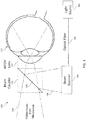
FIG. 1 illustrates asurgical imaging system 100, not belonging to the scope of the claims. Thesurgical imaging system 100 can include alight source 102 configured to generate an imaging light beam. Thelight source 102 can have an operating wavelength in the 0.2-1.8 micron range, the 0.7-1.4 micron range, and/or the 0.9-1.1 micron range. Thesurgical imaging system 100 can include a beam guidance system, including anoptical fiber 104 and/or free space, configured to guide the imaging light beam from the light source. - The
surgical imaging system 100 can also include abeam scanner 106 configured to receive the imaging light from the beam guidance system and generate a scannedimaging light beam 108. Thebeam scanner 106 can be configured to generate the scannedimaging light beam 108 having any desired one-dimensional or two-dimensional scan patterns, including a line, a spiral, a raster, a circular, a cross, a constant-radius asterisk, a multiple-radius asterisk, a multiply folded path, and/or other scan patterns. Thebeam scanner 106 can include one or more of a micro-mirror device, a MEMS based device, a deformable platform, a galvanometer-based scanner, a polygon scanner and/or a resonant PZT scanner. Thebeam scanner 106 can also include focusing optics for defining a depth of focus of the scannedimaging light beam 108. When present, the focusing optics of thebeam scanner 106 can be fixed or adjustable. Adjustable focusing optics or zoom lenses within thebeam scanner 106 can facilitate scanning of a region of interest with increased resolution and depth-of-field. - The surgical imaging system can also include a
beam coupler 110 configured to redirect the scannedimaging light beam 108 towards a wide field of view (WFOV)lens 112 configured to guide the redirected scanned imaging light beam into a target region of aprocedure eye 114. - The
surgical imaging system 100 can also include a surgical microscope. Thebeam coupler 110 can be configured to redirect the scannedimaging light beam 108 into anoptical pathway 116 of the surgical microscope. To redirect the scannedimaging light beam 108 into the target region of theprocedure eye 114 and/or theoptical pathway 116 of the surgical microscope, thebeam coupler 110 can include amirror 118. As shown inFIG. 1 , themirror 118 can be tilted such that it is oriented at an oblique angle with respect to each of the scannedimaging light beam 108 and theoptical pathway 116 of the surgical microscope. Themirror 118 can include a dichroic mirror, a notch filter, a hot mirror, a beamsplitter and/or a cold mirror. Themirror 118 can be configured to combine the visible beam of the microscope with the scannedimaging light beam 108. As a result, the field of view of the scannedimaging light beam 108 and the microscope can overlap completely (as shown inFIGS. 1 ,3 , and7 ), overlap partially (as shown inFIGS. 2 and4 ), or not overlap at all (as shown inFIG. 5 ). - The
mirror 118 can be configured to reflect the scannedimaging light beam 108 and/or reflections from theprocedure eye 114 in the wavelength range of the scannedimaging light beam 108 while allowing the visible beam of the microscope to pass therethrough. Themirror 118 can also be configured to reflect at least a portion of a visible guidance beam coincident with the scannedimaging light beam 108 to facilitate visualization of the scannedimaging light beam 108, which may be outside of the visible range, such as in the infrared range. For example, themirror 118 can include a notch filter in the wavelength range of the visible guidance beam such that the visible guidance beam and its reflections from theprocedure eye 114 can be reflected by themirror 118 along with the scannedimaging light beam 108. - The
beam coupler 110 can be operated with or without a defined optical/optomechanical relationship to the surgical microscope. For example, thebeam coupler 110 can be maintained separate from and independently positionable relative to the surgical microscope. In such instances, thebeam coupler 110 can be a hand-held device, a lens holder, a self-stabilized component or other component. - The
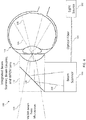
beam coupler 110 and theWFOV lens 112 can be integrated into a common component such that thebeam coupler 110 and theWFOV lens 112 can be collectively, independently positionable relative to the surgical microscope.FIG. 2 illustrates thesurgical imaging system 100 having thebeam coupler 110 and theWFOV lens 112 integrated into a common component, such as a hand-held device, a lens holder, an adapter, or other component. TheWFOV lens 112 can be separate from, but attachable to the integrated optical block component. Theintegrated beam coupler 110 andWFOV lens 112 can be a consumable product configured for use in a single surgical procedure. - The
beam scanner 106 and thebeam coupler 110 can also be integrated into one optical block component.FIG. 3 illustrates thesurgical imaging system 100 having thebeam scanner 106 and thebeam coupler 110 integrated into a common optical block component, such as a hand-held device, a lens holder, an adapter, or other component. TheWFOV lens 112 can be separate from, but attachable to the integrated optical block component. Theintegrated beam scanner 106 andbeam coupler 110 can be a consumable product configured for use in a single surgical procedure. - The
beam scanner 106, thebeam coupler 110, and theWFOV lens 112 can all be integrated into a common component.FIG. 4 illustrates thesurgical imaging system 100 having thebeam scanner 106, thebeam coupler 110, and theWFOV lens 112 integrated into a common component, such as a hand-held device, a lens holder, an adapter, or other component. Theintegrated beam scanner 106,beam coupler 110, andWFOV lens 112 can be a consumable product configured for use in a single surgical procedure. - Referring again to
FIG. 1 , thebeam coupler 110 can be coupled to the surgical microscope, directly or indirectly, such that it has a defined optical/optomechanical relationship to the surgical microscope. For example, thebeam coupler 110 can be coupled to the surgical microscope by one or more of a suspension system, a mechanical frame, a protruding arm, a conical structure, a magnetic member, an elastic member, and a plastic member. TheWFOV lens 112 can be independently manipulable relative to theprocedure eye 114 by a lens-holder-instead of the beam coupler 110-when thebeam coupler 110 is coupled to the surgical microscope in a defined optical/optomechanical relationship. - The
WFOV lens 112 can be configured to provide a field of view of theprocedure eye 114 greater than 15 degrees, greater than 30 degrees, greater than 45 degrees, greater than 60 degrees, greater than 80 degrees and/or greater than 100 degrees. Accordingly, thesurgical imaging system 100 can be configured to provide various field of view ranges, such as between 0 degrees and 30 degrees, between 15 degrees and 80 degrees, between 30 degrees and 120 degrees, , and/or other desired ranges up to ora serrata within the field of view of theWFOV lens 112. TheWFOV lens 112 can be configured to provide the desired refractive power for the diagnostic and/or treatment procedures to be performed on theprocedure eye 114. - The
WFOV lens 112 can be configured to operate spaced from theprocedure eye 114, as a non-contact lens, or in contact with theprocedure eye 114, as a contact lens. For example, anon-contact WFOV lens 112 can be configured to operate in a manner similar to a binocular indirect ophthalmomicroscope (BIOM). Thenon-contact WFOV lens 112 can be positioned by one or more of a mechanical coupling to thebeam coupler 110, a mechanical coupling to the surgical microscope, a suspension system, and a lens holder. TheWFOV lens 112 can also be a contact lens configured to be contacted to theprocedure eye 114. Acontact WFOV lens 112 can be embedded in a stabilizing mechanism, where the stabilizing mechanism can be configured to stabilize thecontact WFOV lens 112 relative to theprocedure eye 114. To that end, the stabilizing mechanism can include one or more of a trocar, a counter weight, a friction-based system, and an elastic system. - The
light source 102, the beam guidance system, and thebeam scanner 106 can be part of an optical coherence tomographic (OCT) imaging system. To that end, theWFOV lens 112 and thebeam coupler 110 can be configured to guide a returned image light from the target region of theprocedure eye 114 back to the OCT imaging system. The returned image light can be interfered with a reference beam of the OCT imaging system, and from the interference an OCT image of the target region in a range of depths can be generated and displayed to a user. The surgical imaging system can be configured to generate the imaging information based on processing the returned image light in less than 30 seconds, less than 10 seconds, and/or less than 5 seconds, including in real time. -
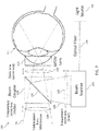
FIG. 5 illustrates thesurgical imaging system 100 according to the claims, having abeam coupler 110 with aprimary mirror 118 and anauxiliary mirror 118. Thebeam coupler 110 can also be integrated with theWFOV lens 112. Thebeam coupler 110 and theWFOV lens 112 are configured to redirect the scannedimaging light beam 108 to angles larger than 15 degrees from an optical axis of theprocedure eye 114. As shown inFIG. 5 , theprimary mirror 118 can be tilted such that it extends at an oblique angle with respect to each of the scannedimaging light beam 108 and theoptical pathway 116 of the surgical microscope, while thesecondary mirror 118 can be positioned such that it extends parallel (or close to parallel) to theoptical pathway 116 of the surgical microscope and/or the optical axis of theprocedure eye 114. As a result, the scannedimaging light beam 108 is reflected from theprimary mirror 118 to thesecondary mirror 118 and through theWFOV lens 112 into theprocedure eye 114. Each of theprimary mirror 118 and thesecondary mirror 118 can include a dichroic mirror, a notch filter, a hot mirror, a mirror, a reflector and/or a cold mirror. Theprimary mirror 118 and thesecondary mirror 118 can have the same or different mirror type and/or features. - The
primary mirror 118 and thesecond mirror 118 can have a fixed orientation such that thesurgical imaging system 100 has a fixed, wide field of view. In that regard, theprimary mirror 118 and thesecond mirror 118, along with theWFOV lens 112, can be configured to provide a field of view of theprocedure eye 114 greater than 15 degrees, greater than 30 degrees, greater than 45 degrees, greater than 60 degrees, greater than 80 degrees and/or greater than 100 degrees. Theprimary mirror 118 and thesecond mirror 118 can be configured to scan in the periphery of theprocedure eye 114. Theprimary mirror 118 and thesecond mirror 118 can also be configured to scan the trabecular meshwork or Schlemm's canal of theprocedure eye 114. Further, theprimary mirror 118 and thesecond mirror 118 can be configured such that the field of view of the scannedimaging beam 108 and the field of view of the visible beam of the microscope do not overlap, as shown inFIG. 5 . Theprimary mirror 118 and thesecond mirror 118 can also be configured such that the field of view of the scannedimaging beam 108 and the field of view of the visible beam of the microscope partially or entirely overlap. Thesecond mirror 118 can also be configured to be adjustable such that the field of view of the scannedimaging beam 108 is covering a changeable region of theprocedure eye 114. - The
beam coupler 110 can be rotatable relative to theprocedure eye 114. In that regard, rotation of thebeam coupler 110 can be utilized to facilitate full circumferential scanning of theprocedure eye 114 and/or to target a particular region of interest within theprocedure eye 114. Rotation of thebeam coupler 110 can be achieved manually (e.g., by physical manipulation by the surgeon) or automatically (e.g., by one or more motorized actuators controlled by a controller of the surgical imaging system 100). The WFOV lens can maintain a fixed orientation relative to theprocedure eye 114 during rotation of thebeam coupler 110. - One or both of the
primary mirror 118 and thesecond mirror 118 can be movable to provide an adjustable field of view for thesurgical imaging system 100. In that regard, in addition to providing a field of view greater than 15 degrees, greater than 30 degrees, greater than 45 degrees, greater than 60 degrees, greater than 80 degrees and/or greater than 100 degrees, theprimary mirror 118 and thesecond mirror 118, along with theWFOV lens 112, can be configured to provide various field of view ranges, such as between 0 degrees and 30 degrees, between 15 degrees and 80 degrees, between 30 degrees and 120 degrees, , and/or other desired ranges up to ora serrata within the field of view of theWFOV lens 112. -
FIG. 6 illustrates anoptical relay system 120 of thesurgical imaging system 100. As shown, theoptical relay system 120 can include anoptical relay 122 configured to guide the scannedimaging light beam 108 to theprocedure eye 114 so that theconjugate pupil plane 124 falls onto thebeam scanner 106 and the scannedimaging light beam 108 pivots at apupil plane 126 of theprocedure eye 114. In that regard, theoptical relay 122 can include any optical components (mirrors, lenses, filters, etc.) between thebeam scanner 106 and thepupil plane 126 of theprocedure eye 114, including optical components of thebeam scanner 106, thebeam coupler 110, theWFOV lens 112, theprocedure eye 114, focusing optics, scanning optics, filtering optics, and/or other optical sub-systems. With thepupil plane 126 conjugate to thebeam scanner 106, beam focusing can be used to optimize/adjust the focus of the scannedimaging beam 108 onto the retina or other regions of interest of theprocedure eye 114. -
FIG. 7 illustrates thesurgical imaging system 100 having at least oneadjustable zoom lens 128. Thesurgical imaging system 100 can include theadjustable zoom lens 128 at one or more of the following locations: between thebeam coupler 110 and a surgical microscope; between thebeam coupler 110 and theWFOV lens 112; between thebeam coupler 110 and thebeam scanner 106; and between thebeam scanner 106 and thelight source 102. Anadjustable zoom lens 128 positioned between thebeam coupler 110 and the surgical microscope can be configured to adjust the focus of theoptical pathway 116 of the surgical microscope. Anadjustable zoom lens 128 positioned between thebeam coupler 110 and thebeam scanner 106 or between thebeam scanner 106 and thelight source 102 can be configured to adjust the focus of the scannedimaging light beam 108. Anadjustable zoom lens 128 positioned between thebeam coupler 110 and theWFOV lens 112 can be configured to adjust the focus of both theoptical pathway 116 of the surgical microscope and the scannedimaging light beam 108. - The adjustable zoom lens(es) 128 can be adjusted by a zoom-controller to adapt an optical power of the surgical imaging system to the desired target region of the
procedure eye 114. Further, the adjustable zoom lens(es) 128 can be controlled by the zoom-controller in real-time to adapt the optical power of the surgical imaging system to keep an aberration below a predetermined value as the scannedimaging beam 108 scans across the target region of theprocedure eye 114. In that regard, the zoom-controller can control eachadjustable zoom lens 128 by adjusting a physical position of the zoom lens (e.g., using piezo-electric or other suitable actuators) and/or adjusting an optical power of the zoom lens without adjusting the physical position of the zoom lens (e.g., by varying a voltage supplied to a liquid crystal zoom lens). - Embodiments as described herein can provide devices, systems, and methods that facilitate real-time, intra-surgical, wide-field of view OCT imaging. The examples provided above are exemplary only and are not intended to be limiting. One skilled in the art may readily devise other systems consistent with the disclosed embodiments which are intended to be within the scope of this disclosure. As such, the application is limited only by the following claims.
Claims (16)
- A surgical imaging system (100) comprising:a surgical microscope;a light source (102), configured to generate an imaging light beam;a beam guidance system (104), configured to guide the imaging light beam from the light source;a beam scanner (106), configured:to receive the imaging light from the beam guidance system, andto generate a scanned imaging light beam (108);a beam coupler (110) configured:to redirect the scanned imaging light beam (108) into an optical pathway (116)of the surgical microscope; anda wide field of view (WFOV) lens (112) configured:wherein the beam coupler (110) comprises a primary mirror and an auxiliary mirror, and is configured to redirect the light beam to angles larger than 15 degrees from an optical axis of the procedure eye, andto contact a procedure eye, andto guide the redirected scanned imaging light beam into a target region of a procedure eye;
wherein the scanned imaging light beam (108) is reflected from the primary mirror (118) to the auxiliary mirror and through the wide field of view (WFOV) lens (112) into the procedure eye. - The surgical imaging system of claim 1, the beam coupler (110) comprising at least one of:
a dichroic mirror, a notch filter, a hot mirror, and a cold mirror in a tilted position. - The surgical imaging system of claim 1, wherein:
the beam scanner (106) and the beam coupler (110) are integrated into one optical block. - The surgical imaging system of claim 1, wherein the WFOV lens (112) is embedded in a stabilizing mechanism configured to stabilize the WFOV lens relative to the procedure eye.
- The surgical imaging system of claim 4, the stabilizing mechanism comprising at least one of: a trocar, a counter weight, a friction-based system, and an elastic system.
- The surgical imaging system of claim 1, wherein:
the WFOV lens (112) has a field of view greater than 15 degrees. - The surgical imaging system of claim 1, wherein:the light source (102), the beam guidance system, and the beam scanner (106) are part of an Optical Coherence Tomographic (OCT) imaging system; andthe WFOV lens (112) and the beam coupler (110) are configured to guide a returned image light from the target region back to the OCT imaging system.
- The surgical imaging system of claim 7, wherein:
the surgical imaging system is configured to generate an imaging information based on processing the returned image light in less than 10 seconds. - The surgical imaging system of claim 1, wherein:
the beam scanner (106) is at least one of a micro-mirror device, a MEMS based device, a deformable platform, a galvanometer-based scanner, a polygon scanner and a resonant PZT scanner. - The surgical imaging system of claim 1, wherein:
the light source (102) has an operating wavelength in the 0.2-1.8 micron wavelength range. - The surgical imaging system of claim 1, wherein:
at least one of the primary mirror (118) and the auxiliary mirror (118) is movable to provide an adjustable field of view. - The surgical imaging system of claim 1, wherein:
the beam coupler (110) is rotatable. - The surgical imaging system of claim 1, comprising:
an optical relay system (120), configured to guide the scanned imaging light beam to the procedure eye so that the conjugate pupil plane falls onto the beam scanner and the imaging light pivots at the pupil plane. - The surgical imaging system of claim 1, comprising at least one of:an adjustable zoom lens (128) between the beam coupler and a surgical microscope;an adjustable zoom lens (128) between the beam coupler and the WFOV lens;an adjustable zoom lens (128) between the beam coupler and the beam scanner; andan adjustable zoom lens (128) between the beam scanner and the light source.
- The surgical imaging system of claim 14, wherein:
an adjustable zoom lens (128) is movable by a zoom-controller to adapt an optical power of the surgical imaging system to keep an aberration below a predetermined value as the scanned imaging beam is scanned in the target region. - The surgical imaging system of claim 1, the beam guidance system comprising at least one of:
a fiber optical guide (104) and a free space guidance system.
Applications Claiming Priority (2)
| Application Number | Priority Date | Filing Date | Title |
|---|---|---|---|
| US201361920347P | 2013-12-23 | 2013-12-23 | |
| PCT/US2014/071153 WO2015100129A1 (en) | 2013-12-23 | 2014-12-18 | Microscope-less wide-field-of-view surgical oct visualization system |
Publications (3)
| Publication Number | Publication Date |
|---|---|
| EP3086706A1 EP3086706A1 (en) | 2016-11-02 |
| EP3086706A4 EP3086706A4 (en) | 2017-10-18 |
| EP3086706B1 true EP3086706B1 (en) | 2021-03-24 |
Family
ID=53398765
Family Applications (1)
| Application Number | Title | Priority Date | Filing Date |
|---|---|---|---|
| EP14873821.4A Active EP3086706B1 (en) | 2013-12-23 | 2014-12-18 | Wide-field-of-view surgical oct visualization system |
Country Status (11)
| Country | Link |
|---|---|
| US (1) | US9554702B2 (en) |
| EP (1) | EP3086706B1 (en) |
| JP (1) | JP6474832B2 (en) |
| KR (1) | KR20160102021A (en) |
| CN (1) | CN105828704B (en) |
| AU (1) | AU2014370109B2 (en) |
| CA (1) | CA2932297C (en) |
| ES (1) | ES2865137T3 (en) |
| MX (1) | MX2016008457A (en) |
| RU (1) | RU2675688C2 (en) |
| WO (1) | WO2015100129A1 (en) |
Families Citing this family (17)
| Publication number | Priority date | Publication date | Assignee | Title |
|---|---|---|---|---|
| WO2018031982A1 (en) * | 2016-08-12 | 2018-02-15 | Alex Artsyukhovich | A surgical laser capsulorhexis system and patient interface lens accessory |
| JP7200091B2 (en) * | 2016-09-16 | 2023-01-06 | アルコン インコーポレイティド | Subtractive frontal light coherence tomography imaging |
| EP3531992B1 (en) * | 2016-10-26 | 2020-11-25 | AMO Development, LLC | Ophthalmic laser delivery apparatus using mems micromirror arrays for scanning and focusing laser beam |
| US10827919B2 (en) | 2017-05-02 | 2020-11-10 | Alcon Inc. | Reconfigurable optical coherence tomography (OCT) system |
| US10765315B2 (en) | 2017-06-21 | 2020-09-08 | Alcon Inc. | Wide field of view, high optical power disposable retina viewing system |
| CN107320066B (en) * | 2017-06-30 | 2023-09-15 | 执鼎医疗科技(杭州)有限公司 | Fundus OCT imaging system sharing reference arm |
| EP3658006B1 (en) * | 2017-10-27 | 2023-03-22 | Alcon Inc. | Foot pedal controlled oct-display for vitreoretinal surgery |
| CN108524097B (en) * | 2018-05-14 | 2024-02-02 | 苏州君信视达医疗科技有限公司 | Laser therapy imaging device |
| AU2019291481A1 (en) * | 2018-06-20 | 2020-11-26 | Alcon Inc. | Auxiliary surgical field visualization system |
| US11173067B2 (en) | 2018-09-07 | 2021-11-16 | Vialase, Inc. | Surgical system and procedure for precise intraocular pressure reduction |
| US11246754B2 (en) | 2018-07-16 | 2022-02-15 | Vialase, Inc. | Surgical system and procedure for treatment of the trabecular meshwork and Schlemm's canal using a femtosecond laser |
| US11110006B2 (en) | 2018-09-07 | 2021-09-07 | Vialase, Inc. | Non-invasive and minimally invasive laser surgery for the reduction of intraocular pressure in the eye |
| US10821024B2 (en) | 2018-07-16 | 2020-11-03 | Vialase, Inc. | System and method for angled optical access to the irido-corneal angle of the eye |
| US10821023B2 (en) | 2018-07-16 | 2020-11-03 | Vialase, Inc. | Integrated surgical system and method for treatment in the irido-corneal angle of the eye |
| CA3168826A1 (en) | 2020-01-22 | 2021-07-29 | Photonic Medical Inc. | Open view, multi-modal, calibrated digital loupe with depth sensing |
| US11564567B2 (en) | 2020-02-04 | 2023-01-31 | Vialase, Inc. | System and method for locating a surface of ocular tissue for glaucoma surgery based on dual aiming beams |
| US11612315B2 (en) | 2020-04-09 | 2023-03-28 | Vialase, Inc. | Alignment and diagnostic device and methods for imaging and surgery at the irido-corneal angle of the eye |
Family Cites Families (23)
| Publication number | Priority date | Publication date | Assignee | Title |
|---|---|---|---|---|
| US7061693B2 (en) * | 2004-08-16 | 2006-06-13 | Xceed Imaging Ltd. | Optical method and system for extended depth of focus |
| US8394084B2 (en) | 2005-01-10 | 2013-03-12 | Optimedica Corporation | Apparatus for patterned plasma-mediated laser trephination of the lens capsule and three dimensional phaco-segmentation |
| US7620147B2 (en) | 2006-12-13 | 2009-11-17 | Oraya Therapeutics, Inc. | Orthovoltage radiotherapy |
| DE102007019812B4 (en) | 2007-04-26 | 2021-08-26 | Carl Zeiss Meditec Ag | Laser surgical device for eye treatment |
| US20100324543A1 (en) * | 2007-09-18 | 2010-12-23 | Kurtz Ronald M | Method And Apparatus For Integrating Cataract Surgery With Glaucoma Or Astigmatism Surgery |
| US10398599B2 (en) * | 2007-10-05 | 2019-09-03 | Topcon Medical Laser Systems Inc. | Semi-automated ophthalmic photocoagulation method and apparatus |
| EP3479753B1 (en) * | 2008-03-19 | 2020-05-13 | Carl Zeiss Meditec AG | Surgical microscopy system having an optical coherence tomography facility |
| EP2296531B1 (en) | 2008-04-23 | 2017-12-27 | Bioptigen, Inc. | Optical coherence tomography (oct) imaging systems for use in pediatric ophthalmic applications and related methods and computer program products |
| US20110096294A1 (en) * | 2009-06-26 | 2011-04-28 | Peyman Gholam A | Non-contact optical coherence tomography imaging of the central and peripheral retina |
| US8366271B2 (en) * | 2010-01-20 | 2013-02-05 | Duke University | Systems and methods for surgical microscope and optical coherence tomography (OCT) imaging |
| US8414564B2 (en) | 2010-02-18 | 2013-04-09 | Alcon Lensx, Inc. | Optical coherence tomographic system for ophthalmic surgery |
| WO2011143387A2 (en) * | 2010-05-13 | 2011-11-17 | Brennan, Jeffrey | Integrated optical coherence tomography systems and methods |
| US9050027B2 (en) | 2010-07-30 | 2015-06-09 | Adventus Technologies, Inc. | Intraoperative imaging system and apparatus |
| CN103314270B (en) * | 2010-12-03 | 2016-03-23 | 光视有限公司 | Use scanning and the process of optical coherent tomography |
| WO2012146708A1 (en) | 2011-04-27 | 2012-11-01 | Carl Zeiss Meditec Ag | Ultra wide-field optical coherence tomography |
| CA2837647A1 (en) * | 2011-05-31 | 2012-12-06 | Vanderbilt University | Optical coherence tomography probe |
| US20140107634A1 (en) | 2011-06-27 | 2014-04-17 | Wavelight Gmbh | Apparatus and method for eye surgery |
| EP2790570B1 (en) * | 2011-12-05 | 2019-09-04 | Bioptigen, Inc. | Optical imaging systems having input beam shape control and path length control |
| EP2815694B1 (en) | 2011-12-30 | 2017-12-06 | WaveLight GmbH | An integrated device for ophthalmology |
| JP5374598B2 (en) | 2012-01-26 | 2013-12-25 | キヤノン株式会社 | Optical tomography system |
| CA2866577A1 (en) | 2012-03-07 | 2013-09-12 | Optovue, Inc. | Enhanced biometry using optical coherence tomography |
| JP5887191B2 (en) | 2012-04-19 | 2016-03-16 | 株式会社トーメーコーポレーション | Corneal imaging apparatus and cornea imaging method |
| CN103251382B (en) * | 2013-04-17 | 2015-10-14 | 温州医学院 | A kind of full eye domain optical coherence tomography system and method thereof |
-
2014
- 2014-12-18 EP EP14873821.4A patent/EP3086706B1/en active Active
- 2014-12-18 AU AU2014370109A patent/AU2014370109B2/en active Active
- 2014-12-18 JP JP2016560636A patent/JP6474832B2/en active Active
- 2014-12-18 CN CN201480070259.1A patent/CN105828704B/en active Active
- 2014-12-18 CA CA2932297A patent/CA2932297C/en active Active
- 2014-12-18 RU RU2016129910A patent/RU2675688C2/en not_active IP Right Cessation
- 2014-12-18 KR KR1020167019689A patent/KR20160102021A/en not_active Application Discontinuation
- 2014-12-18 MX MX2016008457A patent/MX2016008457A/en unknown
- 2014-12-18 WO PCT/US2014/071153 patent/WO2015100129A1/en active Application Filing
- 2014-12-18 ES ES14873821T patent/ES2865137T3/en active Active
- 2014-12-19 US US14/576,306 patent/US9554702B2/en active Active
Non-Patent Citations (1)
| Title |
|---|
| None * |
Also Published As
| Publication number | Publication date |
|---|---|
| ES2865137T3 (en) | 2021-10-15 |
| CN105828704A (en) | 2016-08-03 |
| CA2932297C (en) | 2022-07-05 |
| EP3086706A1 (en) | 2016-11-02 |
| WO2015100129A1 (en) | 2015-07-02 |
| AU2014370109A1 (en) | 2016-06-16 |
| MX2016008457A (en) | 2016-10-12 |
| CA2932297A1 (en) | 2015-07-02 |
| CN105828704B (en) | 2018-06-01 |
| JP2017501004A (en) | 2017-01-12 |
| US9554702B2 (en) | 2017-01-31 |
| JP6474832B2 (en) | 2019-02-27 |
| RU2016129910A3 (en) | 2018-07-20 |
| KR20160102021A (en) | 2016-08-26 |
| AU2014370109B2 (en) | 2019-03-21 |
| RU2016129910A (en) | 2018-01-30 |
| EP3086706A4 (en) | 2017-10-18 |
| US20150173608A1 (en) | 2015-06-25 |
| RU2675688C2 (en) | 2018-12-21 |
Similar Documents
| Publication | Publication Date | Title |
|---|---|---|
| EP3086706B1 (en) | Wide-field-of-view surgical oct visualization system | |
| AU2015290147B2 (en) | Movable wide-angle ophthalmic surgical system | |
| US20160183782A1 (en) | Oct surgical visualization system with macular contact lens | |
| AU2016278755B2 (en) | Tracking system for surgical optical coherence tomography |
Legal Events
| Date | Code | Title | Description |
|---|---|---|---|
| PUAI | Public reference made under article 153(3) epc to a published international application that has entered the european phase |
Free format text: ORIGINAL CODE: 0009012 |
|
| 17P | Request for examination filed |
Effective date: 20160714 |
|
| AK | Designated contracting states |
Kind code of ref document: A1 Designated state(s): AL AT BE BG CH CY CZ DE DK EE ES FI FR GB GR HR HU IE IS IT LI LT LU LV MC MK MT NL NO PL PT RO RS SE SI SK SM TR |
|
| AX | Request for extension of the european patent |
Extension state: BA ME |
|
| DAX | Request for extension of the european patent (deleted) | ||
| A4 | Supplementary search report drawn up and despatched |
Effective date: 20170920 |
|
| RIC1 | Information provided on ipc code assigned before grant |
Ipc: A61B 3/125 20060101AFI20170914BHEP |
|
| STAA | Information on the status of an ep patent application or granted ep patent |
Free format text: STATUS: EXAMINATION IS IN PROGRESS |
|
| 17Q | First examination report despatched |
Effective date: 20190304 |
|
| STAA | Information on the status of an ep patent application or granted ep patent |
Free format text: STATUS: EXAMINATION IS IN PROGRESS |
|
| RAP1 | Party data changed (applicant data changed or rights of an application transferred) |
Owner name: ALCON INC. |
|
| GRAP | Despatch of communication of intention to grant a patent |
Free format text: ORIGINAL CODE: EPIDOSNIGR1 |
|
| STAA | Information on the status of an ep patent application or granted ep patent |
Free format text: STATUS: GRANT OF PATENT IS INTENDED |
|
| INTG | Intention to grant announced |
Effective date: 20200929 |
|
| GRAJ | Information related to disapproval of communication of intention to grant by the applicant or resumption of examination proceedings by the epo deleted |
Free format text: ORIGINAL CODE: EPIDOSDIGR1 |
|
| STAA | Information on the status of an ep patent application or granted ep patent |
Free format text: STATUS: EXAMINATION IS IN PROGRESS |
|
| GRAP | Despatch of communication of intention to grant a patent |
Free format text: ORIGINAL CODE: EPIDOSNIGR1 |
|
| STAA | Information on the status of an ep patent application or granted ep patent |
Free format text: STATUS: GRANT OF PATENT IS INTENDED |
|
| INTC | Intention to grant announced (deleted) | ||
| GRAS | Grant fee paid |
Free format text: ORIGINAL CODE: EPIDOSNIGR3 |
|
| GRAA | (expected) grant |
Free format text: ORIGINAL CODE: 0009210 |
|
| STAA | Information on the status of an ep patent application or granted ep patent |
Free format text: STATUS: THE PATENT HAS BEEN GRANTED |
|
| INTG | Intention to grant announced |
Effective date: 20210208 |
|
| AK | Designated contracting states |
Kind code of ref document: B1 Designated state(s): AL AT BE BG CH CY CZ DE DK EE ES FI FR GB GR HR HU IE IS IT LI LT LU LV MC MK MT NL NO PL PT RO RS SE SI SK SM TR |
|
| REG | Reference to a national code |
Ref country code: GB Ref legal event code: FG4D |
|
| REG | Reference to a national code |
Ref country code: CH Ref legal event code: EP |
|
| REG | Reference to a national code |
Ref country code: IE Ref legal event code: FG4D |
|
| REG | Reference to a national code |
Ref country code: AT Ref legal event code: REF Ref document number: 1373629 Country of ref document: AT Kind code of ref document: T Effective date: 20210415 Ref country code: DE Ref legal event code: R096 Ref document number: 602014076036 Country of ref document: DE |
|
| REG | Reference to a national code |
Ref country code: LT Ref legal event code: MG9D |
|
| PG25 | Lapsed in a contracting state [announced via postgrant information from national office to epo] |
Ref country code: FI Free format text: LAPSE BECAUSE OF FAILURE TO SUBMIT A TRANSLATION OF THE DESCRIPTION OR TO PAY THE FEE WITHIN THE PRESCRIBED TIME-LIMIT Effective date: 20210324 Ref country code: GR Free format text: LAPSE BECAUSE OF FAILURE TO SUBMIT A TRANSLATION OF THE DESCRIPTION OR TO PAY THE FEE WITHIN THE PRESCRIBED TIME-LIMIT Effective date: 20210625 Ref country code: HR Free format text: LAPSE BECAUSE OF FAILURE TO SUBMIT A TRANSLATION OF THE DESCRIPTION OR TO PAY THE FEE WITHIN THE PRESCRIBED TIME-LIMIT Effective date: 20210324 Ref country code: BG Free format text: LAPSE BECAUSE OF FAILURE TO SUBMIT A TRANSLATION OF THE DESCRIPTION OR TO PAY THE FEE WITHIN THE PRESCRIBED TIME-LIMIT Effective date: 20210624 Ref country code: NO Free format text: LAPSE BECAUSE OF FAILURE TO SUBMIT A TRANSLATION OF THE DESCRIPTION OR TO PAY THE FEE WITHIN THE PRESCRIBED TIME-LIMIT Effective date: 20210624 |
|
| PG25 | Lapsed in a contracting state [announced via postgrant information from national office to epo] |
Ref country code: SE Free format text: LAPSE BECAUSE OF FAILURE TO SUBMIT A TRANSLATION OF THE DESCRIPTION OR TO PAY THE FEE WITHIN THE PRESCRIBED TIME-LIMIT Effective date: 20210324 Ref country code: LV Free format text: LAPSE BECAUSE OF FAILURE TO SUBMIT A TRANSLATION OF THE DESCRIPTION OR TO PAY THE FEE WITHIN THE PRESCRIBED TIME-LIMIT Effective date: 20210324 Ref country code: RS Free format text: LAPSE BECAUSE OF FAILURE TO SUBMIT A TRANSLATION OF THE DESCRIPTION OR TO PAY THE FEE WITHIN THE PRESCRIBED TIME-LIMIT Effective date: 20210324 |
|
| REG | Reference to a national code |
Ref country code: NL Ref legal event code: MP Effective date: 20210324 |
|
| REG | Reference to a national code |
Ref country code: AT Ref legal event code: MK05 Ref document number: 1373629 Country of ref document: AT Kind code of ref document: T Effective date: 20210324 |
|
| PG25 | Lapsed in a contracting state [announced via postgrant information from national office to epo] |
Ref country code: NL Free format text: LAPSE BECAUSE OF FAILURE TO SUBMIT A TRANSLATION OF THE DESCRIPTION OR TO PAY THE FEE WITHIN THE PRESCRIBED TIME-LIMIT Effective date: 20210324 |
|
| REG | Reference to a national code |
Ref country code: ES Ref legal event code: FG2A Ref document number: 2865137 Country of ref document: ES Kind code of ref document: T3 Effective date: 20211015 |
|
| PG25 | Lapsed in a contracting state [announced via postgrant information from national office to epo] |
Ref country code: AT Free format text: LAPSE BECAUSE OF FAILURE TO SUBMIT A TRANSLATION OF THE DESCRIPTION OR TO PAY THE FEE WITHIN THE PRESCRIBED TIME-LIMIT Effective date: 20210324 Ref country code: LT Free format text: LAPSE BECAUSE OF FAILURE TO SUBMIT A TRANSLATION OF THE DESCRIPTION OR TO PAY THE FEE WITHIN THE PRESCRIBED TIME-LIMIT Effective date: 20210324 Ref country code: CZ Free format text: LAPSE BECAUSE OF FAILURE TO SUBMIT A TRANSLATION OF THE DESCRIPTION OR TO PAY THE FEE WITHIN THE PRESCRIBED TIME-LIMIT Effective date: 20210324 Ref country code: EE Free format text: LAPSE BECAUSE OF FAILURE TO SUBMIT A TRANSLATION OF THE DESCRIPTION OR TO PAY THE FEE WITHIN THE PRESCRIBED TIME-LIMIT Effective date: 20210324 Ref country code: SM Free format text: LAPSE BECAUSE OF FAILURE TO SUBMIT A TRANSLATION OF THE DESCRIPTION OR TO PAY THE FEE WITHIN THE PRESCRIBED TIME-LIMIT Effective date: 20210324 |
|
| PG25 | Lapsed in a contracting state [announced via postgrant information from national office to epo] |
Ref country code: IS Free format text: LAPSE BECAUSE OF FAILURE TO SUBMIT A TRANSLATION OF THE DESCRIPTION OR TO PAY THE FEE WITHIN THE PRESCRIBED TIME-LIMIT Effective date: 20210724 Ref country code: PT Free format text: LAPSE BECAUSE OF FAILURE TO SUBMIT A TRANSLATION OF THE DESCRIPTION OR TO PAY THE FEE WITHIN THE PRESCRIBED TIME-LIMIT Effective date: 20210726 Ref country code: PL Free format text: LAPSE BECAUSE OF FAILURE TO SUBMIT A TRANSLATION OF THE DESCRIPTION OR TO PAY THE FEE WITHIN THE PRESCRIBED TIME-LIMIT Effective date: 20210324 Ref country code: SK Free format text: LAPSE BECAUSE OF FAILURE TO SUBMIT A TRANSLATION OF THE DESCRIPTION OR TO PAY THE FEE WITHIN THE PRESCRIBED TIME-LIMIT Effective date: 20210324 Ref country code: RO Free format text: LAPSE BECAUSE OF FAILURE TO SUBMIT A TRANSLATION OF THE DESCRIPTION OR TO PAY THE FEE WITHIN THE PRESCRIBED TIME-LIMIT Effective date: 20210324 |
|
| REG | Reference to a national code |
Ref country code: DE Ref legal event code: R097 Ref document number: 602014076036 Country of ref document: DE |
|
| PG25 | Lapsed in a contracting state [announced via postgrant information from national office to epo] |
Ref country code: DK Free format text: LAPSE BECAUSE OF FAILURE TO SUBMIT A TRANSLATION OF THE DESCRIPTION OR TO PAY THE FEE WITHIN THE PRESCRIBED TIME-LIMIT Effective date: 20210324 Ref country code: AL Free format text: LAPSE BECAUSE OF FAILURE TO SUBMIT A TRANSLATION OF THE DESCRIPTION OR TO PAY THE FEE WITHIN THE PRESCRIBED TIME-LIMIT Effective date: 20210324 |
|
| PLBE | No opposition filed within time limit |
Free format text: ORIGINAL CODE: 0009261 |
|
| STAA | Information on the status of an ep patent application or granted ep patent |
Free format text: STATUS: NO OPPOSITION FILED WITHIN TIME LIMIT |
|
| PG25 | Lapsed in a contracting state [announced via postgrant information from national office to epo] |
Ref country code: SI Free format text: LAPSE BECAUSE OF FAILURE TO SUBMIT A TRANSLATION OF THE DESCRIPTION OR TO PAY THE FEE WITHIN THE PRESCRIBED TIME-LIMIT Effective date: 20210324 |
|
| 26N | No opposition filed |
Effective date: 20220104 |
|
| PG25 | Lapsed in a contracting state [announced via postgrant information from national office to epo] |
Ref country code: IS Free format text: LAPSE BECAUSE OF FAILURE TO SUBMIT A TRANSLATION OF THE DESCRIPTION OR TO PAY THE FEE WITHIN THE PRESCRIBED TIME-LIMIT Effective date: 20210724 |
|
| PG25 | Lapsed in a contracting state [announced via postgrant information from national office to epo] |
Ref country code: MC Free format text: LAPSE BECAUSE OF FAILURE TO SUBMIT A TRANSLATION OF THE DESCRIPTION OR TO PAY THE FEE WITHIN THE PRESCRIBED TIME-LIMIT Effective date: 20210324 |
|
| REG | Reference to a national code |
Ref country code: CH Ref legal event code: PL |
|
| REG | Reference to a national code |
Ref country code: BE Ref legal event code: MM Effective date: 20211231 |
|
| PG25 | Lapsed in a contracting state [announced via postgrant information from national office to epo] |
Ref country code: LU Free format text: LAPSE BECAUSE OF NON-PAYMENT OF DUE FEES Effective date: 20211218 Ref country code: IE Free format text: LAPSE BECAUSE OF NON-PAYMENT OF DUE FEES Effective date: 20211218 |
|
| PG25 | Lapsed in a contracting state [announced via postgrant information from national office to epo] |
Ref country code: BE Free format text: LAPSE BECAUSE OF NON-PAYMENT OF DUE FEES Effective date: 20211231 |
|
| PG25 | Lapsed in a contracting state [announced via postgrant information from national office to epo] |
Ref country code: LI Free format text: LAPSE BECAUSE OF NON-PAYMENT OF DUE FEES Effective date: 20211231 Ref country code: CH Free format text: LAPSE BECAUSE OF NON-PAYMENT OF DUE FEES Effective date: 20211231 |
|
| PGFP | Annual fee paid to national office [announced via postgrant information from national office to epo] |
Ref country code: ES Payment date: 20230113 Year of fee payment: 9 |
|
| PG25 | Lapsed in a contracting state [announced via postgrant information from national office to epo] |
Ref country code: HU Free format text: LAPSE BECAUSE OF FAILURE TO SUBMIT A TRANSLATION OF THE DESCRIPTION OR TO PAY THE FEE WITHIN THE PRESCRIBED TIME-LIMIT; INVALID AB INITIO Effective date: 20141218 |
|
| P01 | Opt-out of the competence of the unified patent court (upc) registered |
Effective date: 20230504 |
|
| PG25 | Lapsed in a contracting state [announced via postgrant information from national office to epo] |
Ref country code: CY Free format text: LAPSE BECAUSE OF FAILURE TO SUBMIT A TRANSLATION OF THE DESCRIPTION OR TO PAY THE FEE WITHIN THE PRESCRIBED TIME-LIMIT Effective date: 20210324 |
|
| PGFP | Annual fee paid to national office [announced via postgrant information from national office to epo] |
Ref country code: GB Payment date: 20231116 Year of fee payment: 10 |
|
| PGFP | Annual fee paid to national office [announced via postgrant information from national office to epo] |
Ref country code: IT Payment date: 20231128 Year of fee payment: 10 Ref country code: FR Payment date: 20231122 Year of fee payment: 10 Ref country code: DE Payment date: 20231121 Year of fee payment: 10 |
|
| PGFP | Annual fee paid to national office [announced via postgrant information from national office to epo] |
Ref country code: ES Payment date: 20240118 Year of fee payment: 10 |
|
| PG25 | Lapsed in a contracting state [announced via postgrant information from national office to epo] |
Ref country code: MK Free format text: LAPSE BECAUSE OF FAILURE TO SUBMIT A TRANSLATION OF THE DESCRIPTION OR TO PAY THE FEE WITHIN THE PRESCRIBED TIME-LIMIT Effective date: 20210324 |