EP3086484B1 - Verfahren und vorrichtung zum senden eines rahmen mit partieller assoziationskennung in einem drahtlosen lan-system - Google Patents
Verfahren und vorrichtung zum senden eines rahmen mit partieller assoziationskennung in einem drahtlosen lan-system Download PDFInfo
- Publication number
- EP3086484B1 EP3086484B1 EP14870874.6A EP14870874A EP3086484B1 EP 3086484 B1 EP3086484 B1 EP 3086484B1 EP 14870874 A EP14870874 A EP 14870874A EP 3086484 B1 EP3086484 B1 EP 3086484B1
- Authority
- EP
- European Patent Office
- Prior art keywords
- frame
- sta
- bssid
- paid
- denotes
- Prior art date
- Legal status (The legal status is an assumption and is not a legal conclusion. Google has not performed a legal analysis and makes no representation as to the accuracy of the status listed.)
- Active
Links
Images


Classifications
-
- H—ELECTRICITY
- H04—ELECTRIC COMMUNICATION TECHNIQUE
- H04W—WIRELESS COMMUNICATION NETWORKS
- H04W72/00—Local resource management
- H04W72/04—Wireless resource allocation
- H04W72/044—Wireless resource allocation based on the type of the allocated resource
- H04W72/0446—Resources in time domain, e.g. slots or frames
-
- H—ELECTRICITY
- H04—ELECTRIC COMMUNICATION TECHNIQUE
- H04W—WIRELESS COMMUNICATION NETWORKS
- H04W74/00—Wireless channel access
- H04W74/002—Transmission of channel access control information
- H04W74/004—Transmission of channel access control information in the uplink, i.e. towards network
-
- H—ELECTRICITY
- H04—ELECTRIC COMMUNICATION TECHNIQUE
- H04B—TRANSMISSION
- H04B7/00—Radio transmission systems, i.e. using radiation field
- H04B7/24—Radio transmission systems, i.e. using radiation field for communication between two or more posts
- H04B7/26—Radio transmission systems, i.e. using radiation field for communication between two or more posts at least one of which is mobile
- H04B7/2643—Radio transmission systems, i.e. using radiation field for communication between two or more posts at least one of which is mobile using time-division multiple access [TDMA]
-
- H—ELECTRICITY
- H04—ELECTRIC COMMUNICATION TECHNIQUE
- H04W—WIRELESS COMMUNICATION NETWORKS
- H04W72/00—Local resource management
- H04W72/20—Control channels or signalling for resource management
- H04W72/21—Control channels or signalling for resource management in the uplink direction of a wireless link, i.e. towards the network
-
- H—ELECTRICITY
- H04—ELECTRIC COMMUNICATION TECHNIQUE
- H04W—WIRELESS COMMUNICATION NETWORKS
- H04W72/00—Local resource management
- H04W72/20—Control channels or signalling for resource management
- H04W72/23—Control channels or signalling for resource management in the downlink direction of a wireless link, i.e. towards a terminal
-
- H—ELECTRICITY
- H04—ELECTRIC COMMUNICATION TECHNIQUE
- H04W—WIRELESS COMMUNICATION NETWORKS
- H04W74/00—Wireless channel access
- H04W74/002—Transmission of channel access control information
- H04W74/006—Transmission of channel access control information in the downlink, i.e. towards the terminal
-
- H—ELECTRICITY
- H04—ELECTRIC COMMUNICATION TECHNIQUE
- H04W—WIRELESS COMMUNICATION NETWORKS
- H04W74/00—Wireless channel access
- H04W74/08—Non-scheduled access, e.g. ALOHA
-
- H—ELECTRICITY
- H04—ELECTRIC COMMUNICATION TECHNIQUE
- H04W—WIRELESS COMMUNICATION NETWORKS
- H04W74/00—Wireless channel access
- H04W74/08—Non-scheduled access, e.g. ALOHA
- H04W74/0808—Non-scheduled access, e.g. ALOHA using carrier sensing, e.g. carrier sense multiple access [CSMA]
- H04W74/0816—Non-scheduled access, e.g. ALOHA using carrier sensing, e.g. carrier sense multiple access [CSMA] with collision avoidance
-
- H—ELECTRICITY
- H04—ELECTRIC COMMUNICATION TECHNIQUE
- H04W—WIRELESS COMMUNICATION NETWORKS
- H04W76/00—Connection management
- H04W76/10—Connection setup
- H04W76/11—Allocation or use of connection identifiers
-
- H—ELECTRICITY
- H04—ELECTRIC COMMUNICATION TECHNIQUE
- H04W—WIRELESS COMMUNICATION NETWORKS
- H04W8/00—Network data management
- H04W8/26—Network addressing or numbering for mobility support
-
- H—ELECTRICITY
- H04—ELECTRIC COMMUNICATION TECHNIQUE
- H04W—WIRELESS COMMUNICATION NETWORKS
- H04W84/00—Network topologies
- H04W84/02—Hierarchically pre-organised networks, e.g. paging networks, cellular networks, WLAN [Wireless Local Area Network] or WLL [Wireless Local Loop]
- H04W84/10—Small scale networks; Flat hierarchical networks
- H04W84/12—WLAN [Wireless Local Area Networks]
Definitions
- the present invention relates to a wireless communication system, and more particularly, to a method and apparatus for transmitting and receiving a frame including a Partial Association Identifier (PAID) in a Wireless Local Area Network (WLAN) system.
- PAID Partial Association Identifier
- WLAN Wireless Local Area Network
- WLAN technology from among wireless communication technologies allows wireless Internet access at home or in enterprises or at a specific service provision region using mobile terminals, such as a Personal Digital Assistant (PDA), a laptop computer, a Portable Multimedia Player (PMP), etc. on the basis of Radio Frequency (RF) technology.
- PDA Personal Digital Assistant
- PMP Portable Multimedia Player
- RF Radio Frequency
- IEEE 802.11n enables a data processing speed to support a maximum high throughput (HT) of 540Mbps.
- MIMO Multiple Input and Multiple Output
- Machine-to-Machine (MTM) communication is under discussion as a future-generation communication technology.
- a technical standard supporting M2M communication is also being developed as Institute of Electrical and Electronics Engineers (IEEE) 802.11ah in IEEE 802.11 WLAN.
- IEEE Institute of Electrical and Electronics Engineers
- For M2M communication a scenario in which a very small amount of data is transmitted and received at a low rate from time to time in an environment with a huge number of devices may be considered.
- Communication is conducted on a medium shared among all devices in the WLAN system. If the number of devices increases as is the case with M2M communication, consumption of much time for channel access of one device may obstruct power saving of each device as well as degrade overall system performance.
- An object of the present invention is to provide a new method for configuring a frame including a Partial Association Identifier (PAID).
- PAID Partial Association Identifier
- a new method and apparatus for configuring a frame including a Partial Association Identifier can be provided.
- the following embodiments are proposed by combining constituent components and characteristics of the present invention according to a predetermined format.
- the individual constituent components or characteristics should be considered optional factors on the condition that there is no additional remark. If required, the individual constituent components or characteristics may not be combined with other components or characteristics. In addition, some constituent components and/or characteristics may be combined to implement the embodiments of the present invention.
- the order of operations to be disclosed in the embodiments of the present invention may be changed. Some components or characteristics of any embodiment may also be included in other embodiments, or may be replaced with those of the other embodiments as necessary.
- Exemplary embodiments of the present invention are supported by standard documents disclosed for at least one of wireless access systems including an Institute of Electrical and Electronics Engineers (IEEE) 802 system, a 3 rd Generation Partnership Project (3GPP) system, a 3GPP Long Term Evolution (LTE) system, an LTE-Advanced (LTE-A) system, and a 3GPP2 system.
- 3GPP 3 rd Generation Partnership Project
- LTE Long Term Evolution
- LTE-A LTE-Advanced
- 3GPP2 3 rd Generation Partnership Project 2
- All terminology used herein may be supported by at least one of the above-mentioned documents.
- CDMA Code Division Multiple Access
- FDMA Frequency Division Multiple Access
- TDMA Time Division Multiple Access
- OFDMA Orthogonal Frequency Division Multiple Access
- SC-FDMA Single Carrier Frequency Division Multiple Access
- CDMA may be embodied through wireless (or radio) technology such as Universal Terrestrial Radio Access (UTRA) or CDMA2000.
- TDMA may be embodied through wireless (or radio) technology such as Global System for Mobile communication (GSM)/General Packet Radio Service)/EDGE (Enhanced Data Rates for GSM Evolution (GPRS).
- GSM Global System for Mobile communication
- EDGE Enhanced Data Rates for GSM Evolution
- OFDMA may be embodied through wireless (or radio) technology such as Institute of Electrical and Electronics Engineers (IEEE) 802.11 (Wi-Fi), IEEE 802.16 (WiMAX), IEEE 802-20, and Evolved UTRA (E-UTRA).
- IEEE Institute of Electrical and Electronics Engineers
- Wi-Fi Wi-Fi
- WiMAX IEEE 802.16
- WiMAX WiMAX
- IEEE 802-20 IEEE 802-20
- E-UTRA Evolved UTRA
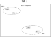
- FIG. 1 exemplarily shows an IEEE 802.11 system according to one embodiment of the present invention.
- the structure of the IEEE 802.11 system may include a plurality of components.
- a WLAN which supports transparent STA mobility for a higher layer may be provided by mutual operations of the components.
- a Basic Service Set (BSS) may correspond to a basic constituent block in an IEEE 802.11 LAN.
- BSS Basic Service Set
- FIG. 1 two BSSs (BSS1 and BSS2) are shown and two STAs are included in each of the BSSs (i.e. STA1 and STA2 are included in BSS1 and STA3 and STA4 are included in BSS2).
- An ellipse indicating the BSS in FIG. 1 may be understood as a coverage area in which STAs included in the corresponding BSS maintain communication. This area may be referred to as a Basic Service Area (BSA). If a STA moves out of the BSA, the STA cannot directly communicate with the other STAs in the corresponding BSA.
- BSA Basic Service Area
- the IBSS may have a minimum form consisting of only two STAs.
- the BSS (BSS1 or BSS2) of FIG. 1 which is the simplest form and in which other components are omitted, may correspond to a typical example of the IBSS.
- Such configuration is possible when STAs can directly communicate with each other.
- Such a type of LAN is not prescheduled and may be configured when the LAN is necessary. This may be referred to as an ad-hoc network.
- STA Memberships of a STA in the BSS may be dynamically changed when the STA is switched on or off or the STA enters or leaves the BSS region.
- the STA may use a synchronization process to join the BSS.
- Such association may be dynamically configured and may include use of a Distribution System Service (DSS).
- DSS Distribution System Service
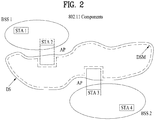
- FIG. 2 is a diagram showing another exemplary structure of an IEEE 802.11 system to which the present invention is applicable.
- components such as a Distribution System (DS), a Distribution System Medium (DSM), and an Access Point (AP) are added to the structure of FIG. 1 .
- DS Distribution System
- DSM Distribution System Medium
- AP Access Point
- a direct STA-to-STA distance in a LAN may be restricted by Physical layer (PHY) performance. In some cases, such restriction of the distance may be sufficient for communication. However, in other cases, communication between STAs over a long distance may be necessary.
- the DS may be configured to support extended coverage.
- the DS refers to a structure in which BSSs are connected to each other.
- a BSS may be configured as a component of an extended form of a network consisting of a plurality of BSSs, instead of independent configuration as shown in FIG. 1 .
- the DS is a logical concept and may be specified by the characteristic of the DSM.
- a Wireless Medium (WM) and the DSM are logically distinguished in IEEE 802.11. Respective logical media are used for different purposes and are used by different components. In definition of IEEE 802.11, such media are not restricted to the same or different media.
- the flexibility of the IEEE 802.11 LAN architecture (DS architecture or other network architectures) can be explained in that a plurality of media is logically different. That is, the IEEE 802.11 LAN architecture can be variously implemented and may be independently specified by a physical characteristic of each implementation.
- the DS may support mobile devices by providing seamless integration of multiple BSSs and providing logical services necessary for handling an address to a destination.
- the AP refers to an entity that enables associated STAs to access the DS through a WM and that has STA functionality. Data may move between the BSS and the DS through the AP.
- STA2 and STA3 shown in FIG. 2 have STA functionality and provide a function of causing associated STAs (STA1 and STA4) to access the DS.
- all APs correspond basically to STAs, all APs are addressable entities. An address used by an AP for communication on the WM need not always be identical to an address used by the AP for communication on the DSM.
- Data transmitted from one of STAs associated with the AP to a STA address of the AP may always be received by an uncontrolled port and may be processed by an IEEE 802.1X port access entity. If the controlled port is authenticated, transmission data (or frame) may be transmitted to the DS.
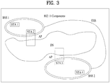
- FIG. 3 is a diagram showing still another exemplary structure of an IEEE 802.11 system to which the present invention is applicable.
- FIG. 3 conceptually shows an Extended Service Set (ESS) for providing wide coverage.
- ESS Extended Service Set
- a wireless network having arbitrary size and complexity may be comprised of a DS and BSSs.
- ESS network In the IEEE 802.11 system, such a type of network is referred to an ESS network.
- the ESS may correspond to a set of BSSs connected to one DS. However, the ESS does not include the DS.
- the ESS network is characterized in that the ESS network appears as an IBSS network in a Logical Link Control (LLC) layer. STAs included in the ESS may communicate with each other and mobile STAs are movable transparently in LLC from one BSS to another BSS (within the same ESS).
- LLC Logical Link Control
- BSSs may partially overlap and this form is generally used to provide continuous coverage.
- BSSs may not be physically connected and the logical distances between BSSs have no limit.
- BSSs may be located at the same physical position and this form may be used to provide redundancy.
- One or more IBSSs or ESS networks may be physically located in the same space as one or more ESS networks. This may correspond to an ESS network form in the case in which an ad-hoc network operates in a location in which an ESS network is present, the case in which IEEE 802.11 networks of different organizations physically overlap, or the case in which two or more different access and security policies are necessary in the same location.
- FIG. 4 is a diagram showing an exemplary structure of a WLAN system.
- an example of an infrastructure BSS including a DS is shown.
- BSS1 and BSS2 constitute an ESS.
- a STA is a device operating according to MAC/PHY regulation of IEEE 802.11.
- STAs include AP STAs and non-AP STAs.
- the non-AP STAs correspond to devices, such as laptop computers or mobile phones, handled directly by users.
- STA1, STA3, and STA4 correspond to the non-AP STAs and STA2 and STA5 correspond to AP STAs.
- the non-AP STA may be referred to as a terminal, a Wireless Transmit/Receive Unit (WTRU), a User Equipment (UE), a Mobile Station (MS), a mobile terminal, or a Mobile Subscriber Station (MSS).
- the AP is a concept corresponding to a Base Station (BS), a Node-B, an evolved Node-B (e-NB), a Base Transceiver System (BTS), or a femto BS in other wireless communication fields.
- BS Base Station
- e-NB evolved Node-B
- BTS Base Transceiver System
- femto BS femto BS in other wireless communication fields.
- a processor may implement the layer architecture in terms of device configuration.
- the STA may have a plurality of layers.
- the 802.11 standards mainly deal with a MAC sublayer and a PHY layer on a Data Link Layer (DLL).
- the PHY layer may include a Physical Layer Convergence Protocol (PLCP) entity, a Physical Medium Dependent (PMD) entity, and the like.
- PLCP Physical Layer Convergence Protocol
- PMD Physical Medium Dependent
- Each of the MAC sublayer and the PHY layer conceptually includes management entities called MAC sublayer Management Entity (MLME) and Physical Layer Management Entity (PLME). These entities provide layer management service interfaces through which a layer management function is executed.
- MLME MAC sublayer Management Entity
- PLME Physical Layer Management Entity
- a Station Management Entity resides in each STA.
- the SME is a layer independent entity which may be perceived as being present in a separate management plane or as being off to the side. While specific functions of the SME are not described in detail herein, the SME may be responsible for collecting layer-dependent states from various Layer Management Entities (LMEs) and setting layer-specific parameters to similar values. The SME may execute these functions and implement a standard management protocol on behalf of general system management entities.
- LMEs Layer Management Entities
- a primitive refers to a set of elements or parameters related to a specific purpose.
- An XX-GET.request primitive is used to request a predetermined MIB attribute value (management information-based attribute information).
- An XX-GET.confirm primitive is used to return an appropriate MIB attribute information value when the Status field indicates "Success" and to return an error indication in the Status field when the Status field does not indicate "Success”.
- An XX-SET.request primitive is used to request setting of an indicated MIB attribute to a predetermined value.
- the MIB attribute When the MIB attribute indicates a specific operation, the MIB attribute requests the specific operation to be performed.
- An XX-SET.confirm primitive is used to confirm that the indicated MIB attribute has been set to a requested value when the Status field indicates "Success" and to return an error condition in the Status field when the Status field does not indicate "Success".
- the MIB attribute When the MIB attribute indicates a specific operation, it confirms that the operation has been performed.
- the MLME and the SME may exchange various MLME_GET/SET primitives through an MLME Service Access Point (MLME_SAP).
- various PLME_GET/SET primitives may be exchanged between the PLME and the SME through a PLME_SAP, and exchanged between the MLME and the PLME through an MLME-PLME_SAP.
- FIG. 5 is a flowchart explaining a general link setup process according to an exemplary embodiment of the present invention.
- the link setup process may also be referred to as a session initiation process or a session setup process.
- an association step is a generic term for discovery, authentication, association, and security setup steps of the link setup process.
- STA may perform the network discovery action.
- the network discovery action may include the STA scanning action. That is, STA must search for an available network so as to access the network.
- the STA must identify a compatible network before participating in a wireless network.
- the process for identifying the network contained in a specific region is referred to as a scanning process.
- the scanning scheme is classified into active scanning and passive scanning.
- FIG. 5 is a flowchart illustrating a network discovery action including an active scanning process.
- a STA configured to perform scanning transmits a probe request frame and waits for a response to the probe request frame, such that the STA can move between channels and at the same time can determine which Access Point (AP) is present in a peripheral region.
- a responder transmits a probe response frame, acting as a response to the probe request frame, to the STA having transmitted the probe request frame.
- the responder may be a STA that has finally transmitted a beacon frame in a BSS of the scanned channel. In BSS, since the AP transmits the beacon frame, the AP operates as a responder.
- the responder since STAs of the IBSS sequentially transmit the beacon frame, the responder is not constant. For example, the STA, that has transmitted the probe request frame at Channel #1 and has received the probe response frame at Channel #1, stores BSS-associated information contained in the received probe response frame, and moves to the next channel (for example, Channel #2), such that the STA may perform scanning using the same method (i.e., probe request/response transmission/reception at Channel #2).
- the scanning action may also be carried out using passive scanning.
- a STA configured to perform scanning in the passive scanning mode waits for a beacon frame while simultaneously moving from one channel to another channel.
- the beacon frame is one of management frames in IEEE 802.11, indicates the presence of a wireless network, enables the STA performing scanning to search for the wireless network, and is periodically transmitted in a manner that the STA can participate in the wireless network.
- the AP is configured to periodically transmit the beacon frame.
- STAs of the IBSS are configured to sequentially transmit the beacon frame. If each STA for scanning receives the beacon frame, the STA stores BSS information contained in the beacon frame, and moves to another channel and records beacon frame information at each channel.
- the STA having received the beacon frame stores BSS-associated information contained in the received beacon frame, moves to the next channel, and thus performs scanning using the same method.
- the active scanning is more advantageous than the passive scanning in terms of delay and power consumption.
- the STA may perform the authentication process in step S520.
- the authentication process may be referred to as a first authentication process in such a manner that the authentication process can be clearly distinguished from the security setup process of step S540.
- the authentication process may include transmitting an authentication request frame to an AP by the STA, and transmitting an authentication response frame to the STA by the AP in response to the authentication request frame.
- the authentication frame used for authentication request/response may correspond to a management frame.
- the authentication frame may include an authentication algorithm number, an authentication transaction sequence number, a state code, a challenge text, a Robust Security Network (RSN), a Finite Cyclic Group (FCG), etc.
- the above-mentioned information contained in the authentication frame may correspond to some parts of information capable of being contained in the authentication request/response frame, may be replaced with other information, or may include additional information.
- the STA may transmit the authentication request frame to the AP.
- the AP may decide whether to authenticate the corresponding STA on the basis of information contained in the received authentication request frame.
- the AP may provide the authentication result to the STA through the authentication response frame.
- the association process may involve transmitting an association request frame to the AP by the STA, and transmitting an association response frame to the STA by the AP in response to the association request frame.
- the association request frame may include information associated with various capabilities, a beacon listen interval, a Service Set Identifier (SSID), supported rates, supported channels, RSN, mobility domain, supported operating classes, a TIM (Traffic Indication Map) broadcast request, interworking service capability, etc.
- SSID Service Set Identifier
- supported rates supported channels
- RSN mobility domain
- supported operating classes e.g., mobility management services, etc.
- TIM Traffic Indication Map
- the association response frame may include information associated with various capabilities, a state code, an Association ID (AID), supported rates, an Enhanced Distributed Channel Access (EDCA) parameter set, a Received Channel Power Indicator (RCPI), a Received Signal to Noise Indicator (RSNI), mobility domain, a timeout interval (association comeback time), an overlapping BSS scan parameter, a TIM broadcast response, a Quality of Service (QoS) map, etc.
- AID Association ID
- EDCA Enhanced Distributed Channel Access
- RCPI Received Channel Power Indicator
- RSNI Received Signal to Noise Indicator
- mobility domain a timeout interval (association comeback time)
- association comeback time an overlapping BSS scan parameter
- a TIM broadcast response a Quality of Service (QoS) map, etc.
- QoS Quality of Service
- the above-mentioned information may correspond to some parts of information capable of being contained in the association request/response frame, may be replaced with other information, or may include additional information.
- a security setup process may be carried out in step S540.
- the security setup process of Step S540 may be referred to as an authentication process based on Robust Security Network Association (RSNA) request/response.
- the authentication process of step S520 may be referred to as a first authentication process, and the security setup process of Step S540 may also be simply referred to as an authentication process.
- RSNA Robust Security Network Association
- the security setup process of Step S540 may include a private key setup process through 4-way handshaking based on an Extensible Authentication Protocol over LAN (EAPOL) frame.
- the security setup process may also be carried out according to other security schemes not defined in IEEE 802.11 standards.
- IEEE 802.11n In order to obviate limitations in WLAN communication speed, IEEE 802.11n has recently been established as a communication standard. IEEE 802.11n aims to increase network speed and reliability as well as to extend a coverage region of the wireless network. In more detail, IEEE 802.11n supports a High Throughput (HT) of a maximum of 540Mbps, and is based on MIMO technology in which multiple antennas are mounted to each of a transmitter and a receiver.
- HT High Throughput
- the next generation WLAN system for supporting Very High Throughput is the next version (for example, IEEE 802.11ac) of the IEEE 802.11n WLAN system, and is one of IEEE 802.11 WLAN systems recently proposed to support a data process speed of 1Gbps or more at a Medium Access Control Service Access Point (MAC SAP).
- IEEE 802.11ac the next version of the IEEE 802.11n WLAN system
- MAC SAP Medium Access Control Service Access Point
- the next generation WLAN system supports Multi User Multiple Input Multiple Output (MU-MIMO) transmission in which a plurality of STAs can simultaneously access a channel.
- MU-MIMO Multi User Multiple Input Multiple Output
- the AP may simultaneously transmit packets to at least one MIMO-paired STA.
- the whitespace may be a licensed band capable of being primarily used only by a licensed user.
- the licensed user may be a user who has authority to use the licensed band, and may also be referred to as a licensed device, a primary user, an incumbent user, or the like.
- an AP and/or STA operating in the White Space must provide a function for protecting the licensed user.
- the licensed user such as a microphone has already used a specific WS channel acting as a divided frequency band on regulation in a manner that a specific bandwidth is occupied from the WS band
- the AP and/or STA cannot use the frequency band corresponding to the corresponding WS channel so as to protect the licensed user.
- the AP and/or STA must stop using the corresponding frequency band under the condition that the licensed user uses a frequency band used for transmission and/or reception of a current frame.
- the AP and/or STA must determine whether to use a specific frequency band of the WS band. In other words, the AP and/or STA must determine the presence or absence of an incumbent user or a licensed user in the frequency band.
- the scheme for determining the presence or absence of the incumbent user in a specific frequency band is referred to as a spectrum sensing scheme.
- An energy detection scheme, a signature detection scheme and the like may be used as the spectrum sensing mechanism.
- the AP and/or STA may determine that the frequency band is being used by an incumbent user if the intensity of a received signal exceeds a predetermined value, or when a DTV preamble is detected.
- M2M communication technology has been discussed as next generation communication technology.
- Technical standard for supporting M2M communication has been developed as IEEE 802.11ah in the IEEE 802.11 WLAN system.
- M2M communication refers to a communication scheme including one or more machines, or may also be referred to as Machine Type Communication (MTC) or M2M communication.
- MTC Machine Type Communication
- M2M communication may be an entity that does not require direct handling and intervention of a user.
- UE user equipment
- M2M communication may include Device-to-Device (D2D) communication and communication between a device and an application server, etc.
- D2D Device-to-Device
- M2M-based communication applications may include security, transportation, healthcare, etc.
- M2M communication has to support the method for sometimes transmitting/receiving a small amount of data at low speed under an environment including a large number of devices.
- M2M communication must support a large number of STAs.
- the current WLAN system assumes that one AP is associated with a maximum of 2007 STAs, various methods for supporting other cases in which many more STAs (e.g., about 6000 STAs) are associated with one AP have recently been discussed in M2M communication.
- many applications for supporting/requesting a low transfer rate are present in M2M communication.
- the WLAN system may recognize the presence or absence of data to be transmitted to the STA on the basis of a Traffic Indication Map (TIM), and various methods for reducing the bitmap size of the TIM have recently been discussed.
- TIM Traffic Indication Map
- M2M communication it is expected that much traffic data having a very long transmission/reception interval is present in M2M communication.
- a very small amount of data e.g., electric/gas/water metering
- the STA operates according to a command received via downlink (i.e., a link from the AP to the non-AP STA) in M2M communication, such that data is reported through uplink (i.e., a link from the non-AP STA to the AP).
- downlink i.e., a link from the AP to the non-AP STA
- uplink i.e., a link from the non-AP STA to the AP
- an M2M STA is mainly operated as a battery and the user may feel difficulty in frequently charging the M2M STA with electricity, such that battery consumption is minimized, resulting in an increased battery lifetime.
- the user may have difficulty in directly handling the M2M STA in a specific situation, such that a self-recovery function is needed. Therefore, although the number of STAs associated with one AP increases in the WLAN system, many developers and companies are conducting intensive research into an WLAN system which can efficiently support the case in which there are a very small number of STAs, each of which has a data frame to be received from the AP during one beacon period, and at the same time can reduce power consumption of the STA.
- WLAN technology is rapidly developing, and not only the above-mentioned exemplary technologies but also other technologies such as a direct link setup, improvement of media streaming throughput, high-speed and/or support of large-scale initial session setup, and support of extended bandwidth and operation frequency, are being intensively developed.
- the IEEE 802.11ah standard in which M2M communication is set to a use case has recently been discussed.
- the IEEE 802.11ah standard is operated in an unlicensed band other than a TV whitespace band at a sub-1GHz operation frequency, and has a wider coverage (for example, a maximum of 1km) than a legacy WLAN mainly supporting a conventional indoor coverage. That is, differently from the legacy WLAN operated at a frequency of 2.4GHz or 5GHz, if a WLAN is operated at an operation frequency of sub-1GHz (for example, 700 ⁇ 900 MHz), the AP coverage is increased about two or three times as compared to the same Transmit (Tx) power due to propagation characteristics of the corresponding band.
- Tx Transmit
- Use Case 1 Sensors and meters - 1a: Smart Grid - Meter to Pole - 1c: Environmental/Agricultural Monitoring - 1d: Industrial process sensors - 1e: Healthcare - 1f: Healthcare - 1g: Home/Building Automation - 1h: Home sensors
- Use Case 2 Backhaul Sensor and meter data - Backhaul aggregation of sensors - Backhaul aggregation of industrial sensors
- Use Case 3 Extended range Wi-Fi - Outdoor extended range hotspot - Outdoor Wi-Fi for cellular traffic offloading
- M2M communication in which various kinds of sensors/meter devices are connected to an 802.11ah AP is made available.
- smart grid technology enables a maximum of 6000 sensors/meter devices to be connected to one AP.
- an 802.11ah AP configured to provide a large coverage serves as a backhaul link of a different system such as IEEE 802.15.4g.
- Use Case 3 may support extended home coverage, campus wide coverage, and outdoor extended range hotspot communication such as shopping-mall range hotspot communication.
- an 802.11ah AP supports traffic offloading of cellular mobile communication, such that cellular traffic overload can be scattered.
- a Physical (PHY) layer for sub-1GHz communication is implemented by performing 1/10 down-clocking of the legacy IEEE 802.11ac PHY.
- the channel bandwidth of 20/40/80/160/80+80 MHz for use in 802.11ac is provided through 1/10 down-clocking, and the channel bandwidth of 2/4/8/16/8+8 MHz is provided at sub-1GHz. Therefore, a Guard Interval (GI) is increased from 0.8 ⁇ s to 8 ⁇ s, such that the GI is increased ten fold.
- GI Guard Interval
- Table 2 shows the result of comparison between 802.11ac PHY throughput and 1/10 down-clocked sub-1GHz PHY throughput.
- a basic access mechanism of MAC is a Carrier Sense Multiple Access with Collision Avoidance (CSMA/CA) mechanism.
- the CSMA/CA mechanism is referred to as a Distributed Coordination Function (DCF) of IEEE 802.11 MAC, and basically includes a "Listen Before Talk" access mechanism.
- DCF Distributed Coordination Function
- the AP and/or STA may perform Clear Channel Assessment (CCA) for sensing an RF channel or medium during a predetermined time interval [for example, DCF Inter-Frame Space (DIFS)], prior to data transmission. If it is determined that the medium is in the idle state, frame transmission through the corresponding medium begins.
- CCA Clear Channel Assessment
- the corresponding AP and/or STA does not start its own transmission, establishes a delay time (for example, a random backoff period) for medium access, and attempts to start frame transmission after waiting for a predetermined time.
- a delay time for example, a random backoff period
- HCF Hybrid Coordination Function
- PCF Point Coordination Function
- EDCA Enhanced Distributed Channel Access
- HCCA HCF Controlled Channel Access
- EDCA is achieved when the access scheme provided from a provider to a plurality of users is contention-based.
- HCCA is achieved by the contention-free-based channel access scheme based on the polling mechanism.
- HCF includes a medium access mechanism for improving Quality of Service (QoS) of WLAN, and may transmit QoS data in both a Contention Period (CP) and a Contention Free Period (CFP).
- QoS Quality of Service
- FIG. 6 is a conceptual diagram illustrating a backoff process.
- each STA selects a random backoff count, waits for a slot time corresponding to the selected backoff count, and then attempts to start data transmission.
- the random backoff count is a pseudo-random integer, and may be set to one of 0 to CW values. In this case, CW refers to a Contention Window parameter value.
- CWmin an initial value of the CW parameter
- the initial value may be doubled in case of a transmission failure (for example, in the case in which ACK of the transmission frame is not received).
- CWmax CWmax is maintained until data transmission is successful, and at the same time it is possible to attempt to start data transmission. If data transmission was successful, the CW parameter value is reset to CWmin.
- the STA continuously mon i tors the medium while counting down the backoff slot in response to the decided backoff count value. If the medium is monitored as the occupied state, the countdown stops and waits for a predetermined time. If the medium is in the idle state, the remaining countdown restarts.
- the STA3 determines whether the medium is in the idle state during the DIFS, and may directly start frame transmission. In the meantime, the remaining STAs monitor whether the medium is in the busy state, and wait for a predetermined time. During the predetermined time, data to be transmitted may occur in each of STA1, STA2, and STA5. If the medium is in the idle state, each STA waits for the DIFS time and then performs countdown of the backoff slot in response to a random backoff count value selected by each STA. The example of FIG. 6 shows that STA2 selects the lowest backoff count value and STA1 selects the highest backoff count value.
- the residual backoff time of STA5 at a frame transmission start time is shorter than the residual backoff time of STA1.
- Each of STA1 and STA5 temporarily stops countdown while STA2 occupies the medium, and waits for a predetermined time. If occupying of the STA2 is finished and the medium re-enters the idle state, each of STA1 and STA5 waits for a predetermined time DIFS, and restarts backoff counting. That is, after the remaining backoff slot as long as the residual backoff time is counted down, frame transmission may start operation. Since the residual backoff time of STA5 is shorter than that of STA1, STA5 starts frame transmission.
- data to be transmitted may occur in STA4 while STA2 occupies the medium.
- STA4 waits for the DIFS time, performs countdown in response to the random backoff count value selected by the STA4, and then starts frame transmission.
- FIG. 6 exemplarily shows the case in which the residual backoff time of STA5 is identical to the random backoff count value of STA4 by chance.
- an unexpected collision may occur between STA4 and STA5. If the collision occurs between STA4 and STA5, each of STA4 and STA5 does not receive ACK, resulting in the occurrence of a failure in data transmission.
- each of STA4 and STA5 increases the CW value two times, and STA4 or STA5 may select a random backoff count value and then perform countdown.
- STA1 waits for a predetermined time while the medium is in the occupied state due to transmission of STA4 and STA5. In this case, if the medium is in the idle state, STA1 waits for the DIFS time, and then starts frame transmission after lapse of the residual backoff time.
- the CSMA/CA mechanism includes not only a physical carrier sensing mechanism in which the AP and/or STA can directly sense the medium, but also a virtual carrier sensing mechanism.
- the virtual carrier sensing mechanism can solve some problems (such as a hidden node problem) encountered in the medium access.
- MAC of the WLAN system can utilize a Network Allocation Vector (NAV).
- NAV Network Allocation Vector
- the AP and/or STA each of which currently uses the medium or has authority to use the medium, may inform another AP and/or another STA for the remaining time in which the medium is available.
- the NAV value may correspond to a reserved time in which the medium will be used by the AP and/or STA configured to transmit the corresponding frame.
- a STA having received the NAV value may prohibit or defer medium access (or channel access) during the corresponding reserved time.
- NAV may be set according to the value of a 'duration' field of the MAC header of the frame.
- the robust collision detect mechanism has been proposed to reduce the probability of such collision, and as such a detailed description thereof will hereinafter be described with reference to FIGS. 7 and 8 .
- an actual carrier sensing range is different from a transmission range, it is assumed that the actual carrier sensing range is identical to the transmission range for convenience of description and better understanding of the present invention.
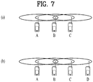
- FIG. 7 is a conceptual diagram illustrating a hidden node and an exposed node.
- FIG. 7(a) exemplarily shows the hidden node.
- STA A communicates with STA B, and STA C has information to be transmitted.
- STA C may determine that the medium is in the idle state when performing carrier sensing before transmitting data to STA B, under the condition that STA A transmits information to STA B. Since transmission of STA A (i.e., occupied medium) may not be detected at the location of STA C, it is determined that the medium is in the idle state. In this case, STA B simultaneously receives information of STA A and information of STA C, resulting in the occurrence of collision.
- STA A may be considered as a hidden node of STA C.
- FIG. 7(b) exemplarily shows an exposed node.
- STA C under the condition that STA B transmits data to STA A, STA C has information to be transmitted to STA D. If STA C performs carrier sensing, it is determined that the medium is occupied due to transmission of STA B. Therefore, although STA C has information to be transmitted to STA D, the medium-occupied state is sensed, such that the STA C must wait for a predetermined time (i.e., standby mode) until the medium is in the idle state.
- a predetermined time i.e., standby mode
- STA C is referred to as an exposed node of STA B.
- FIG. 8 is a conceptual diagram illustrating Request To Send (RTS) and Clear To Send (CTS).
- RTS/CTS short signaling packet
- RTS/CTS between two STAs may be overheard by peripheral STA(s), such that the peripheral STA(s) may consider whether information is communicated between the two STAs. For example, if STA to be used for data transmission transmits the RTS frame to the STA having received data, the STA having received data transmits the CTS frame to peripheral STAs, and may inform the peripheral STAs that the STA is going to receive data.
- FIG. 8(a) exemplarily shows the method for solving problems of the hidden node.
- STA A and STA C are ready to transmit data to STA B. If STA A transmits RTS to STA B, STA B transmits CTS to each of STA A and STA C located in the vicinity of the STA B. As a result, STA C must wait for a predetermined time until STA A and STA B stop data transmission, such that collision is prevented from occurring.
- FIG. 8(b) exemplarily shows the method for solving problems of the exposed node.
- STA C performs overhearing of RTS/CTS transmission between STA A and STA B, such that STA C may determine no collision although it transmits data to another STA (for example, STA D). That is, STA B transmits an RTS to all peripheral STAs, and only STA A having data to be actually transmitted can transmit a CTS.
- STA C receives only the RTS and does not receive the CTS of STA A, such that it can be recognized that STA A is located outside of the carrier sensing range of STA C.
- PLCP Physical Layer Convergence Protocol
- PPDU Packet Data Unit
- a PPDU frame format may include a Short Training Field (STF), a Long Training Field (LTF), a Signal (SIG) field, and a Data field.
- the most basic PPDU frame format (e.g., a non-High Throughput (non-HT) frame format) may include only a Legacy-STF (L-STF), a Legacy-LTF (L-LTF), a SIG field, and a DATA field.
- An additional (or a different type of) STF, LTF, and SIG field may be included between the SIG field and the DATA field according to the type of a PPDU frame format (e.g., HT-mixed format PPDU, HT-greenfield format PPDU, Very High Throughput (VHT) PPDU, or the like).
- a PPDU frame format e.g., HT-mixed format PPDU, HT-greenfield format PPDU, Very High Throughput (VHT) PPDU, or the like.
- the STF is a signal used for signal detection, Automatic Gain Control (AGC), diversity selection, precise time synchronization, and the like
- the LTF is a signal used for channel estimation, frequency error estimation, and the like. Both the STF and the LTF may be collectively referred to as a PCLP preamble, and it may be said that the PLCP preamble is a signal used for synchronization and channel estimation of an OFDM PHY layer.
- the SIG field may include a RATE field and a LENGTH field.
- the RATE field may include information about the modulation scheme and coding rate of data.
- the LENGTH field may include information about the length of the data.
- the SIG field may further include parity bits, SIG TAIL bits, and the like.
- the DATA field may include a SERVICE field, a PLCP Service Data Unit (PSDU), and PPDU TAIL bits, and when needed, padding bits.
- a part of the bits of the SERVICE field may be used for synchronization of a descrambler at a receiving end.
- the PSDU may correspond to a MAC PDU defined at the MAC layer and include data generated/used by a higher layer.
- the PPDU TAIL bits may be used to return an encoder to a zero state.
- the padding bits may be used to match the length of the DATA field on a predetermined unit basis.
- a MAC PDU is defined according to various MAC frame formats.
- a basic MAC frame includes a MAC header, a frame body, and a Frame Check Sequence (FCS).
- a MAC frame may include a MAC PDU and transmitted/received in a PSDU of the data part of the PPDU frame format.
- a Null Data Packet (NDP) frame format is a frame format that does not include a data packet. That is, an NDP frame is a frame that includes only the PLCP header part (i.e., the STF, LTF, and SIG field) of the general PPDU format, without the other part (i.e., the DATA field) of the general PPDU format.
- the NDP frame format may be referred to as a short frame format.
- the present invention proposes a method for configuring a SIG field in an SU frame and an MU frame in a WLAN system operating at sub-1GHz (e.g., 902 to 928MHz).
- the SU frame may be used in SU-MIMO
- the MU frame may be used in MU-MIMO.
- a frame may be a data frame or an NDP frame.
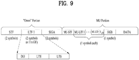
- FIG. 9 is a diagram illustrating an exemplary SU/MU frame format.
- an STF, LTF 1, a Signal A (SIG-A) field correspond to an omni portion in the sense that they are transmitted to all STAs omnidirectionally, and the omni portion may be transmitted without beamforming or precoding.
- the SU/MU frame format is a non-NDP frame format.
- an MU-STF, MU-LTF1, ..., MU-LTF_N LTF , and a Signal B (SIG-B) field that follow the SIG-A field are transmitted user-specifically, and may be transmitted through beamforming or precoding.
- An MU portion may include an MU-STF, MU-STF(s), a SIG-B field, and a DATA field in the exemplary frame format of FIG. 9 .
- k represents a subcarrier (or tone) index
- x k represents a signal transmitted on subcarrier k
- N TX represents the number of Tx antennas.
- Q k represents a column vector by which the signal transmitted on subcarrier k is encoded (e.g., spatially mapped)
- d k represents data input to an encoder.
- time-domain Cyclic Shift Delay may be applied to Q k .
- Time-domain CSD is equivalent to frequency-domain phase rotation or phase shift. Therefore, Q k may include a phase shift value for tone k, caused by time-domain CSD.
- all STAs may receive the STF, LTF1, and SIG-A field, and each STA may decode the SIG-A field by channel estimation based on the STF and LTF1.
- the SIG-A field may include information about a length/duration, a channel bandwidth, the number of spatial streams, and so on.
- the SIG-A field is two OFDM symbols long. Because one OFDM symbol uses Binary Phase Shift Keying (BPSK) for 48 data tones, the OFDM symbol may represent 24-bit information. Therefore, the SIG-A field may include 48-bit information.
- BPSK Binary Phase Shift Keying
- [Table 3] below illustrates exemplary bit allocations of the SIG-A field for an SU case and an MU case.
- [Table 3] SU MU SU/MU Indication 1 1 Length/Duration 9 9 MCS 4 BW 2 2 Aggregation 1 STBC 1 1 Coding 2 5 SGI 1 1 GID 6 Nsts 2 8 Uplink/Downlink 1 PAID Uplink: 9 Downlink: 6 COLOR Uplink: 0 Downlink: 3 ACK Indication 2 2 Reserved 2 3 CRC 4 4 Tail 6 6 Total 48 48
- the SU/MU Indication field is used to distinguish an SU frame format from an MU frame format.
- the Length/Duration field indicates the number of OFDM symbols (i.e., duration) or bytes (i.e., length) of the frame. If the Aggregation field of an SU frame is set to 1, the Length/Duration field is interpreted as a Duration field, whereas if the Aggregation field of the SU frame is set to 0, the Length/Duration field is interpreted as a Length field.
- the Aggregation field is not defined for an MU frame and the MU frame is configured so that aggregation may always be applied. Accordingly, the Length/Duration field is interpreted as a Duration field for the MU frame.
- the Modulation and Coding Scheme (MCS) field indicates an MCS used for PSDU transmission.
- the MCS field is transmitted in the SIG-A field, only for an SU frame. If other STAs (i.e., third party STAs with no direct relation to transmission and reception between two STAs) receive the SU frame, they may calculate the duration of the current received SU frame (i.e., an SU-beamformed frame with an Aggregation field set to 0) based on the values of the Length/Duration and MCS fields.
- the MCS field is not included in the SIG-A field but in the SIG-B field carrying user-specific information. Thus, an MCS is applicable to each user independently.
- the BandWidth (BW) field indicates the channel bandwidth of the transmitted SU or MU frame.
- the BW field may be set to a value indicating one of 2MHz, 4MHz, 8MHz, 16MHz, and 8+8MHz.
- the Aggregation field indicates whether PSDUs are combined into an MPDU (i.e., Aggregated MPDU (A-MPDU)). If the Aggregation field is set to 1, this means that PSDUs are combined into an A-MPDU and transmitted. If the Aggregation field is set to 0, this means that PSDUs are not combined into an A-MPDU and transmitted. Because PSDUs are always transmitted in an A-MPDU in an MU frame, there is no need for signaling the Aggregation field and thus the Aggregation field is not included in the SIG-A field in the MU frame.
- A-MPDU Aggregated MPDU
- the Space and Time Block Coding (STBC) field indicates whether STBC is applied to the SU frame or the MU frame.
- the Coding field indicates a coding scheme used for the SU frame or the MU frame.
- BCC Binary Convolutional Code
- LDPC Low Density Parity Check
- an independent coding scheme may be used for each user, and to support the independent coding, the Coding field may be defined to be two or more bits.
- the Short Guard Interval (SGI) field indicates whether an SGI is used for PSDU transmission in the SU frame or the MU frame. If an SGI is used in the MU frame, this may imply that the SGI is applied commonly to all users belonging to an MU-MIMO group.
- SGI Short Guard Interval
- the Group Identifier (GID) field provides MU group information in the MU frame. For the SU frame, there is no need for defining a user group and thus the GID field is not included in the SIG-A field.
- the Number of space-time streams (Nsts) field indicates the number of spatial streams in the SU frame or the MU frame.
- the Nsts field indicates the number of spatial streams for each of STAs belonging to an MU group, and for this purpose, the Nsts field needs 8 bits.
- one MU group may include four users at maximum and up to four spatial streams may be transmitted for each user, the Nsts field needs eight bits.
- the Uplink/Downlink field explicitly indicates whether the frame is a UL frame or a DL frame. It may be regulated preliminarily that the Uplink/Downlink field is defined only for an SU frame, not for an MU frame and the MU frame is always a DL frame.
- the Partial Association Identifier (PAID) field indicates the ID of a receiving STA in the SU frame.
- the PAID is a part of a Basic Service Set Identifier (BSSID).
- BSSID Basic Service Set Identifier
- the PAID may be configured by hashing the BSSID of an AP and the AID of a STA.
- a BSSID is the MAC address of an AP, 48 bits long.
- An AID is identification information or an address that an AP allocates to a STA associated with the AP, which is 16 bits long.
- the PAID field may be defined to be 9 bits long in a UL frame, and 6 bits long in a DL frame. A method for determining a PAID value will be described below in detail.
- the COLOR field is not defined for a UL frame, whereas the COLOR field may be defined to be 3 bits long for a DL frame.
- the COLOR field may have a value ranging from 0 to 7.
- the COLOR field may be used for the purpose of identifying a BSS which has transmitted a DL frame.
- the STA may determine whether the frame has been transmitted from a BSS to which the STA belongs by the COLOR field. Meanwhile, in the case of a UL frame, since it is possible to identify a BSS transmitting the frame just with the PAID field, the COLOR field is not included in the SIG-A field.
- the ACK indication field listed in [Table 3] indicates the type of an ACK transmitted after the SU frame or the MU frame. For example, if the value of the ACK indication field is 00, it indicates a normal ACK, if the value of the ACK indication field is 01, it indicates a block ACK, and the value of the ACK indication field is 10, it indicates no ACK.
- the ACK indication field is not limited to the three types, and three or more types of ACKs may be defined according to the properties of response frames.
- the SIG-B field of an MU frame may include user-specific information, as illustrated in the example of FIG. 9 .
- [Table 4] below lists exemplary fields of the SIG-B field in the MU frame. Also, the following [Table 1] lists various parameters applied to a PPDU with respect to the respective BWs of 2, 4, 8, and 16MHz. [Table 4] BW 2 MHz 4 MHz 8 MHz 16 MHz MCS 4 4 4 4 4 4 4 4 4 4 4 4 4 4 4 4 4 4 4 4 4 4 4 4 4 4 4 4 4 4 Tail 6 6 6 6 6 CRC 8 8 8 8 Reserved 8 9 11 11 Total 26 27 29 29
- the MCS field indicates the MCS value of a PPDU transmitted in an MU frame, for each user.
- the TAIL bits may be used to return an encoder to a zero state.
- the Cyclic Redundancy Check (CRC) field may be used to detect errors by a STA receiving the MU frame.
- a PAID is a non-unique ID of a STA. As described before with reference to [Table 3], the PAID may be included in an SU frame. Specifically, the PAID may be included in an SU frame defined for a sub-1GHz operating frequency to which the present invention is applicable.
- [Table 5] below describes a conventional method for determining a PAID value according to each frame type.
- Condition PAID Addressed to AP [Equation 2] ( dec (BSSID[39:47]) mod (2 9 -1))+1 Addressed to Mesh STA [Equation 3] BSSID [40:47]
- dec(A) represents the decimal value of a binary value A.
- A[b:c] represents bit b to bit c of the binary value A, when the first bit of the binary value A is bit 0.
- Mod represents a modulo operation, XOR represents an exclusive OR operation, and
- represents a concatenation operation.
- a PAID value may be calculated by representing the 40 th to 48 th nine bits of a 48-bit BSSID (i.e., BSSID[39:47] represents bit 39 to bit 47 of the BSSID) as a decimal value, performing a (2 9 -1) modulo operation on the decimal value, and adding 1 to the result of the modulo operation. Because 1 is added to the result of the modulo operation, the PAID value is calculated to be a non-zero value in this case.
- condition "Sent by an AP and addressed to a STA associated with that AP” corresponds to a case in which an AP transmits a DL frame to a STA associated with the AP.
- condition "sent by a DLS or TDLS STA in a direct path to a DLS or TDLS STA” corresponds to a case in which one Direct Link Setup (DLS) or Tunneled DLS (TDLS) STA transmits a frame to another DLS or TDLS STA via a direct path.
- a PAID is calculated by hashing a BSSID and an AID.
- AID[0:8] eight bits at the 1 st to 9 th positions of an AID (i.e., AID[0:8]) are represented as a decimal value.
- bits at the 45 th to 48 th positions of a BSSID i.e., BSSID[44:47]
- four bits at the 41th to 44 th positions of the BSSID i.e., BSSID[40:43]
- a PAID is calculated by adding the two decimal values and performing a 2 6 modulo operation on the sum.
- a PAID value is 0 for a frame that an AP multicasts/broadcasts to all STAs or a frame transmitted by a non-associated STA. This implies that if the value of the PAID field of a frame detected by a STA is 0, the STA receives the frame and performs PSDU decoding.
- an AP decodes a PSDU, determining that the frame is destined (or highly likely to be destined) for the AP.
- a STA decodes a PSDU, determining that the frame is destined (or highly likely to be destined) for the STA.
- the AP when allocating an AID to a STA, the AP should not allocate the STA to an AID which results in 0 as the value of ( dec (AID[0:8]+ dec (BSSID[44:47] XOR BSSID[40:43]) ⁇ 2 5 ) mod 2 6 . If the AP allocates the STA to an AID which results in 0 as the value of ( dec (AID[0:8]+ dec (BSSID[44:47] XOR BSSID[40:43]) ⁇ 2 5 ) mod 2 6 , the PAID of a DL frame transmitted to the STA is 0 according to [Table 5]. As a result, all other STAs capable of detecting this frame receive the frame and perform PSDU decoding, determining that the frame is a multicast/broadcast frame, thereby obstructing an overall system operation.
- the AP when allocating an AID to a STA, the AP should not allocate the STA to an AID which results in 0 as the value of ( dec (AID[0:8]+ dec (BSSID[44:47] XOR BSSID[40:43]) ⁇ 2 5 ) mod 2 6 .
- the STA unnecessarily receive a UL frame transmitted to the AP by any other STA and perform PSDU decoding, determining that the frame is destined for the STA.
- the AP In the presence of an Overlapping BSS (OBSS), the AP should determine an AID value to be allocated to a STA that belongs to its BSS, in consideration of the BSSID of an OBSS AP (i.e., the BSSID of the OBSS). In other words, when allocating an AID to the STA, the AP should not allocate the STA to an AID that results in ( dec (OBSS BSSID[39:47]) mod (2 9 -1))+1 as the value of ( dec (AID[0:8]+ dec (BSSID[44:47] XOR BSSID[40:43]) ⁇ 2 5 ) mod 2 6 .
- dec (OBSS BSSID[39:47]) mod (2 9 -1) the value of ( dec (AID[0:8]+ dec (BSSID[44:47] XOR BSSID[40:43]) ⁇ 2 5 ) mod 2 6 .
- the STA may unnecessarily receive an OBSS UL frame that a STA belonging to the OBSS transmits to the AP of the OBSS, and perform PSDU decoding, determining that the OBSS UL frame is destined for the STA.
- a PAID value for a DL frame calculated by hashing an AID with a BSSID should be different from a PAID value set for a specific frame type such as a multicast/broadcast frame or a PAID value set for a specific STA, as in a UL frame transmitted to the AP or the OBSS AP.
- an AID value that may cause this case should not be allocated to an individual STA, and it is preferred that the AID value is used for another usage such as a multicast frame or the like.
- [Table 5] is modified to [Table 6] as follows.
- [Table 6] Condition PAID A frame that is not a Control frame that is Addressed to AP [Equation 2] ( dec (BSSID[39:47]) mod (2 9 -1))+1 Addressed to Mesh STA [Equation 3] BSSID [40:47]
- [Equation 4] dec (AID[0:8]+ dec (BSSID[44:47] XOR BSSID[40:43]) ⁇ 2 5 ) mod 2 6 Otherwise 0
- the PAID of the frame is set to 0.
- the present invention proposes a method for setting a specific value as the PAID value of a control frame in order to solve a problem encountered with the conventional PAID determination method. Additionally, the present invention proposes a method for setting the Uplink/Downlink field or COLOR field of the SIG-A field of a control frame to a specific value.
- Control frame types include, for example, RTS frame, CTS frame, ACK frame, Block ACK frame, Power Save-Poll (PS-Poll) frame, and Contention Free-END (CF-END) frame.
- a control frame may include a Duration field in its MAC header, and adjacent STAs may set Network Allocation Vectors (NAVs) for virtual carrier sensing by detecting or overhearing the control frame.
- NAVs Network Allocation Vectors
- the STAs which have set NAVs, defer channel access (or medium access) during a predetermined time period.
- control frame should be transmitted in such a manner that the control frame may be overheard by all adjacent STAs, not limited to a BSS (or an AP) to which the STA belongs, there is no need for defining (or configuring) a COLOR field, and for this purpose, the control frame may be transmitted as a UL frame type. Accordingly, the Uplink/Downlink field is set to a value indicating UL frame and the COLOR field is not included, in the control frame.
- the PAID may be set to 0 and the COLOR field may be set to the COLOR value of the BSS to which the STA transmitting the control frame belongs, in the control frame, so that STAs may identify an ongoing frame exchange sequence in a BSS to which they belong.
- the Uplink/Downlink field of the control frame is set to a value indicating DL frame.
- control frame is for the purpose of overhearing by setting the PAID of the control frame to 0, and the COLOR field of the control frame to a specific value (e.g., 0) at the STA transmitting the control frame, in order to indicate STAs that the STAs are supposed to decode the corresponding frame exchange sequence irrespective of their BSS.
- the Uplink/Downlink field of the control frame is set to a value indicating DL frame.
- FIG. 10 is a flowchart illustrating an exemplary method for transmitting and receiving a frame according to the present invention.
- a transmission entity may determine whether a frame to be transmitted is a UL frame (i.e., a frame directed from a non-AP STA to an AP) or a DL frame (i.e., a frame directed from an AP to a STA).
- a UL frame i.e., a frame directed from a non-AP STA to an AP
- a DL frame i.e., a frame directed from an AP to a STA.
- the transmission entity proceeds to step S1020, and in the case of a DL frame, the transmission entity proceeds to step S1030.
- step S1020 the transmission entity determines whether the UL frame to be transmitted is a control frame. If the UL frame to be transmitted is a control frame, the transmission entity sets the PAID of the frame to be transmitted to 0 in step S1040. If the UL frame to be transmitted is not a control frame, the transmission entity calculates the PAID of the frame based on the BSSID of the AP (e.g., according to [Equation 2] in [Table 6]) in step S1050.
- the BSSID of the AP e.g., according to [Equation 2] in [Table 6]
- step S1030 the transmission entity determines whether the DL frame to be transmitted is a control frame. If the DL frame to be transmitted is a control frame, the transmission entity sets the PAID of the frame to 0 in step S1060. If the DL frame to be transmitted is not a control frame, the transmission entity calculates the PAID of the frame based on the AID of the STA and the BSSID of the AP (e.g., according to [Equation 4] in [Table 6]) in step S1070.
- a reception entity e.g., an AP STA or a non-AP STA
- a reception entity receives the frame checks the PAID of the detected frame and decodes a PSDU of the frame, if the PAID is identical to the PAID of the reception entity (e.g., in the case of an AP STA, if a value calculated by [Equation 2] in [Table 6] is equal to the PAID value of the detected frame, and in the case of a non-AP STA, if a value calculated by [Equation 4] in [Table 6] is equal to the PAID value of the detected frame) or the PAID is 0.
- FIG. 10 While the exemplary method depicted in FIG. 10 is described as a series of operations, for clarity of description, this does not limit the order of steps. When needed, the steps may be performed at the same time or in a different order. Moreover, all steps depicted in FIG. 10 are not needed to implement the method proposed by the present invention.
- the method for transmitting and receiving a frame (especially, the PAID configuring method) according to the present invention, depicted in FIG. 10 , may be implemented so that the foregoing various embodiments of the present invention may be applied independently or two or more of them may be applied simultaneously.
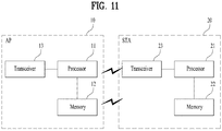
- FIG. 11 is a block diagram of wireless apparatuses according to an embodiment of the present invention.
- An AP 10 may include a processor 11, a memory 12, and a transceiver 13, and a STA 20 may include a processor 21, a memory 22, and a transceiver 23.
- the transceivers 13 and 23 may be configured to transmit and receive wireless signals, and implement the PHY layer according to, for example, an IEEE 802 system.
- the processors 11 and 12 may be connected to the transceivers 13 and 23, and may implement the PHY layer and/or the MAC layer according to the IEEE 802 system.
- the processors 11 and 21 may be configured to perform operations according to the foregoing various embodiments of the present invention. Also, modules for performing AP operations and STA operations according to the various embodiments of the present invention may be stored in the memories 12 and 22 and executed by the processors 11 and 21.
- the memories 12 and 22 may reside inside or outside of the processors 11 and 21 and may be connected to the processors 11 and 21 by known means.
- the processor 11 may be configured to determine whether the frame (i.e., a DL frame) is a control frame. If the DL frame is a control frame, the processor 11 may set the PAID of the DL frame to 0. If the DL frame is not a control frame, the processor 11 may calculate/set the PAID of the DL frame based on the AID of a STA and the BSSID of the AP (e.g., according to [Equation 4] in [Table 6]).
- the processor 11 may be configured to decode a PSDU of the UL frame.
- the processor 21 may be configured to determine whether the frame (i.e., a UL frame) is a control frame. If the UL frame is a control frame, the processor 21 may set the PAID of the UL frame to 0. If the UL frame is not a control frame, the processor 21 may calculate/set the PAID of the UL frame based on the BSSID of the AP (e.g., according to [Equation 2] in [Table 6]).
- the processor 21 may be configured to decode a PSDU of the DL frame.
- the above-described AP and STA may be configured specifically in such a manner that the descriptions of the foregoing various embodiments may be implemented independently or two or more of the embodiments may be implemented simultaneously, and a redundant description is avoided for clarity.
- the embodiments of the present invention may be achieved by various means, for example, hardware, firmware, software, or a combination thereof.
- the method according to the embodiments of the present invention may be implemented by one or more Application Specific Integrated Circuits (ASICs), Digital Signal Processors (DSPs), Digital Signal Processing Devices (DSPDs), Programmable Logic Devices (PLDs), Field Programmable Gate Arrays (FPGAs), processors, controllers, microcontrollers, or microprocessors.
- ASICs Application Specific Integrated Circuits
- DSPs Digital Signal Processors
- DSPDs Digital Signal Processing Devices
- PLDs Programmable Logic Devices
- FPGAs Field Programmable Gate Arrays
- processors controllers, microcontrollers, or microprocessors.
- the method according to the embodiments of the present invention may be implemented in the form of modules, procedures, functions, etc. performing the above-described functions or operations.
- Software code may be stored in a memory unit and executed by a processor.
- the memory unit may be located at the interior or exterior of the processor and may transmit and receive data to and from the processor via various known means.
Landscapes
- Engineering & Computer Science (AREA)
- Computer Networks & Wireless Communication (AREA)
- Signal Processing (AREA)
- Databases & Information Systems (AREA)
- Mobile Radio Communication Systems (AREA)
Claims (15)
- Verfahren zum Senden eines Rahmens durch eine Station, STA, die zu einem Basic Service Set, BSS, gehört, in einem drahtlosen Kommunikationssystem, wobei das Verfahren umfasst:Festlegen einer partiellen Assoziationskennung, PAID, für einen zu sendenden Rahmen; undSenden des Rahmens einschließlich der PAID,wobei, falls der Rahmen kein Steuerrahmen ist, die PAID auf einen von Null verschiedenen Wert gesetzt wird (S1050, S1070), der unter Verwendung einer Basic-Service-Set-Kennung, BSSID, des BSS berechnet wird; undwobei, falls der Rahmen ein Steuerrahmen ist, die PAID auf Null gesetzt wird (S1040, S1060).
- Verfahren nach Anspruch 1, wobei, falls die STA eine Nichtzugangspunkt-STA, Nicht-AP-STA, ist und der Rahmen ein Uplink-Rahmen ist, der kein Steuerrahmen ist, der von Null verschiedene Wert der PAID auf der Grundlage der BSSID berechnet wird (S1050).
- Verfahren nach Anspruch 2, wobei der von Null verschiedene Wert der PAID des Uplink-Rahmens, der kein Steuerrahmen ist, als (dec(BSSID[39:47])mod(29-1))+1 berechnet wird (S1050),
wobei BSSID die BSSID des BSS bezeichnet, dec(A) einen Dezimalwert einer Binärzahl A bezeichnet, A[b:c] Bit b bis Bit c der Binärzahl A bezeichnet, wobei ein Anfangsbit der Binärzahl A Bit 0 ist, und mod eine Modulo-Operation bezeichnet. - Verfahren nach einem der vorangehenden Ansprüche, wobei der Rahmen ein Nicht-Null-Datenpaket-Rahmen, Nicht-NDP-Rahmen, ist.
- Verfahren nach einem der vorangehenden Ansprüche, wobei der Rahmen ein Uplink/Downlink-Angabefeld einschließt.
- Verfahren nach einem der vorangehenden Ansprüche, wobei eine Größe der PAID 9 Bits für einen Uplink-Rahmen beträgt.
- Verfahren nach Anspruch 6, wobei eine Größe der PAID 6 Bits für einen Downlink-Rahmen beträgt.
- Verfahren nach Anspruch 7, wobei der Downlink-Rahmen ferner BSS-COLOR-Informationen von drei Bits einschließt.
- Verfahren nach einem der vorangehenden Ansprüche, wobei, falls die STA ein Zugangspunkt, AP, des BSS ist, wobei der Rahmen ein an eine andere STA zu sendender Downlink-Rahmen ist und der Downlink-Rahmen kein Steuerrahmen ist, der von Null verschiedene Wert der PAID auf der Grundlage der BSSID und einer Assoziationskennung, AID, die der anderen STA durch den AP zugewiesen wird, berechnet wird (S1070).
- Verfahren nach Anspruch 9, wobei der von Null verschiedene Wert der PAID des Downlink-Rahmens, der kein Steuerrahmen ist, als dec(AID[0:8]+dec(BSSID[44:47] XOR BSSID[40:43])x25)mod26 berechnet wird (S1070),
wobei AID die der anderen STA zugewiesene AID bezeichnet, BSSID die BSSID des BSS bezeichnet, dec(A) einen Dezimalwert einer Binärzahl A bezeichnet, A[b:c] Bit b bis Bit c der Binärzahl A darstellt, wobei ein Anfangsbit der Binärzahl A Bit 0 ist, und mod eine Modulo-Operation bezeichnet. - Station, STA, zum Senden eines Rahmens in einem drahtlosen Kommunikationssystem, wobei die STA umfasst:einen Transceiver (23) zum Kommunizieren in einem Basic Service Set, BSS, zu dem die STA gehört; undeinen Prozessor (21),wobei der Prozessor so konfiguriert ist, dass er einen Rahmen einschließlich einer partiellen Assoziationskennung, PAID, durch Steuern des Transceivers sendet undwobei der Prozessor ferner so konfiguriert ist, dass er die PAID auf einen von Null verschiedenen, unter Verwendung einer Basic-Service-Set-Kennung, BSSID, des BSS berechneten Wert setzt (S1050, S1070), falls der Rahmen kein Steuerrahmen ist, und die PAID auf Null setzt (S1040, S1060), falls der Rahmen ein Steuerrahmen ist.
- STA nach Anspruch 11, wobei der Prozessor so konfiguriert ist, dass er den von Null verschiedenen Wert der PAID auf der Grundlage der BSSID berechnet (S1050), falls die STA eine Nichtzugangspunkt-STA, Nicht-AP-STA, ist und der Rahmen ein Uplink-Rahmen ist, der kein Steuerrahmen ist, (S1050).
- STA nach Anspruch 12, wobei der Prozessor so konfiguriert ist, dass er den von Null verschiedenen Wert der PAID des Uplink-Rahmens, der kein Steuerrahmen ist, als (dec(BSSID[39:47])mod(29-1))+1 berechnet (S1050),
wobei BSSID die BSSID bezeichnet, dec(A) einen Dezimalwert einer Binärzahl A bezeichnet, A[b:c] Bit b bis Bit c der Binärzahl A bezeichnet, wobei ein Anfangsbit der Binärzahl A Bit 0 ist, und mod eine Modulo-Operation bezeichnet. - STA nach einem der Ansprüche 11 bis 13, wobei der Prozessor so konfiguriert ist, dass er, falls die STA ein Zugangspunkt, AP, des BSS ist, wobei der Rahmen ein an eine andere STA zu sendender Downlink-Rahmen ist und der Downlink-Rahmen kein Steuerrahmen ist, den von Null verschiedenen Wert der PAID auf der Grundlage der BSSID und einer Assoziationskennung, AID, die der anderen STA durch den AP zugewiesen ist, berechnet (S1070).
- STA nach Anspruch 14, wobei der Prozessor so konfiguriert ist, dass er den von Null verschiedenen Wert der PAID des Downlink-Rahmens, der kein Steuerrahmen ist, als dec(AID[0:8]+dec(BSSID[44:47] XOR BSSID[40:43])x25)mod26 berechnet (S1070),
wobei AID die der anderen STA zugewiesene AID bezeichnet, BSSID die BSSID des BSS bezeichnet, dec(A) einen Dezimalwert einer Binärzahl A bezeichnet, A[b:c] Bit b bis Bit c der Binärzahl A darstellt, wobei ein Anfangsbit der Binärzahl A Bit 0 ist, und mod eine Modulo-Operation bezeichnet.
Applications Claiming Priority (3)
| Application Number | Priority Date | Filing Date | Title |
|---|---|---|---|
| US201361919611P | 2013-12-20 | 2013-12-20 | |
| US201461924216P | 2014-01-06 | 2014-01-06 | |
| PCT/KR2014/006003 WO2015093704A1 (ko) | 2013-12-20 | 2014-07-04 | 무선랜 시스템에서 부분 연관 식별자를 포함하는 프레임 송수신 방법 및 장치 |
Publications (3)
| Publication Number | Publication Date |
|---|---|
| EP3086484A1 EP3086484A1 (de) | 2016-10-26 |
| EP3086484A4 EP3086484A4 (de) | 2017-08-30 |
| EP3086484B1 true EP3086484B1 (de) | 2018-11-28 |
Family
ID=53403024
Family Applications (1)
| Application Number | Title | Priority Date | Filing Date |
|---|---|---|---|
| EP14870874.6A Active EP3086484B1 (de) | 2013-12-20 | 2014-07-04 | Verfahren und vorrichtung zum senden eines rahmen mit partieller assoziationskennung in einem drahtlosen lan-system |
Country Status (9)
| Country | Link |
|---|---|
| US (1) | US10129874B2 (de) |
| EP (1) | EP3086484B1 (de) |
| JP (1) | JP6419821B2 (de) |
| KR (1) | KR102232426B1 (de) |
| CN (1) | CN105830361B (de) |
| AU (1) | AU2014367655B2 (de) |
| CA (1) | CA2933033C (de) |
| RU (1) | RU2639296C1 (de) |
| WO (1) | WO2015093704A1 (de) |
Families Citing this family (26)
| Publication number | Priority date | Publication date | Assignee | Title |
|---|---|---|---|---|
| US10205573B2 (en) * | 2013-09-13 | 2019-02-12 | Futurewei Technologies, Inc. | System and method for OFDMA PS-poll transmission |
| WO2015120488A1 (en) * | 2014-02-10 | 2015-08-13 | Mediatek Inc. | Method for identifying source bss in wlan |
| KR102082094B1 (ko) | 2014-05-13 | 2020-02-27 | 주식회사 윌러스표준기술연구소 | 클리어 채널 할당을 위한 무선 통신 방법 및 이를 이용한 무선 통신 단말 |
| EP4293971A3 (de) * | 2014-06-27 | 2024-02-14 | Samsung Electronics Co., Ltd. | Verfahren und vorrichtung zur datenübertragung |
| KR102082095B1 (ko) | 2014-08-18 | 2020-02-27 | 주식회사 윌러스표준기술연구소 | 데이터 동시 통신을 위한 무선 통신 방법 및 이를 이용한 무선 통신 단말 |
| KR102814666B1 (ko) | 2014-12-02 | 2025-05-30 | 주식회사 윌러스표준기술연구소 | 클리어 채널 할당을 위한 무선 통신 단말 및 무선 통신 방법 |
| US10021721B2 (en) * | 2015-01-28 | 2018-07-10 | Newracom, Inc. | Transmission control method |
| US10485028B2 (en) | 2015-10-02 | 2019-11-19 | Lg Electronics Inc. | Method for supporting multi-BSS in wireless LAN system and device therefor |
| CN112566181B (zh) * | 2015-10-20 | 2024-05-17 | 华为技术有限公司 | 无线局域网中站点间直接通信的方法及相关设备 |
| CN107027128B (zh) | 2016-02-02 | 2019-12-24 | 华为技术有限公司 | 信息传输方法及节点 |
| CN109076614B (zh) | 2016-04-02 | 2022-08-16 | 韦勒斯标准与技术协会公司 | 重叠的基本服务集的空间重用的无线通信方法和无线通信终端 |
| ES2875510T3 (es) * | 2016-04-02 | 2021-11-10 | Wilus Inst Standards & Tech Inc | Método de comunicaciones inalámbricas y terminal de comunicaciones inalámbricas que usan una determinación de información de identificación de un conjunto de servicios básicos de una trama recibida |
| CN105978653B (zh) * | 2016-04-28 | 2018-05-15 | 西安电子科技大学 | 在交叠基本服务集下的干扰消除方法 |
| RU2769950C2 (ru) * | 2016-11-02 | 2022-04-11 | Панасоник Интеллекчуал Проперти Корпорэйшн оф Америка | Устройство связи и способ связи |
| US10637549B2 (en) * | 2017-01-17 | 2020-04-28 | Qualcomm Incorporated | Methods and systems for coordinating distributed MIMO communications |
| CN109429268B (zh) * | 2017-08-30 | 2022-08-02 | 珠海市魅族科技有限公司 | 无线局域网的通信方法、装置、接入点设备和站点设备 |
| US11259285B2 (en) * | 2018-02-27 | 2022-02-22 | Qualcomm Incorporated | Co-located basic service sets |
| US10993197B2 (en) * | 2018-05-30 | 2021-04-27 | Nxp Usa, Inc. | Distributed MIMO based on access point collaboration |
| US11271617B2 (en) * | 2018-10-03 | 2022-03-08 | Qualcomm Incorporated | Null data packet-based implicit sounding and calibration in a wireless local area network |
| CN113993090B (zh) | 2020-07-27 | 2024-04-09 | 华为技术有限公司 | 适用于多链路的组播业务传输方法及装置 |
| CN121531480A (zh) * | 2020-08-05 | 2026-02-13 | 松下电器(美国)知识产权公司 | 无线通信装置及无线通信方法 |
| CN114071506A (zh) | 2020-08-07 | 2022-02-18 | 华为技术有限公司 | 适用于多链路的单播业务指示方法及相关装置 |
| CN112579566B (zh) * | 2020-12-14 | 2023-03-31 | 浪潮云信息技术股份公司 | 分布式id的生成方法及装置 |
| US11818706B2 (en) * | 2021-04-27 | 2023-11-14 | Cisco Technology, Inc. | Mesh performance using overlapping basic service set (OBSS) coloring and transmission scheduling |
| CN115865283A (zh) | 2021-09-23 | 2023-03-28 | 华为技术有限公司 | 无线帧发送方法及装置、无线帧接收方法及装置 |
| CN116233850A (zh) * | 2021-12-02 | 2023-06-06 | 联发科技股份有限公司 | 防止攻击方法和使用该方法的接入点 |
Family Cites Families (12)
| Publication number | Priority date | Publication date | Assignee | Title |
|---|---|---|---|---|
| JP3322394B2 (ja) * | 1998-12-08 | 2002-09-09 | 日本電気株式会社 | マルチアクセス通信システム |
| US7577438B2 (en) * | 2005-04-25 | 2009-08-18 | Interdigital Technology Corporation | Method and system for efficient addressing and power savings in wireless systems |
| US8600336B2 (en) * | 2005-09-12 | 2013-12-03 | Qualcomm Incorporated | Scheduling with reverse direction grant in wireless communication systems |
| CN1988533B (zh) * | 2005-12-19 | 2012-10-17 | 华为技术有限公司 | 一种实现IuUP/NBUP协议过程控制功能的方法 |
| CN104486281B (zh) | 2009-12-03 | 2018-04-20 | Lg电子株式会社 | 在无线ran系统中发送帧的方法和装置 |
| US8787284B2 (en) * | 2010-03-15 | 2014-07-22 | Lg Electronics Inc. | Method and apparatus for transmitting frame in WLAN system |
| EP2579477B1 (de) * | 2010-05-26 | 2017-04-19 | LG Electronics Inc. | Verfahren und vorrichtung zum senden und empfangen von daten in einem wlan-system |
| US8675678B2 (en) * | 2010-09-10 | 2014-03-18 | The Johns Hopkins University | Adaptive medium access control |
| US8917743B2 (en) * | 2010-10-06 | 2014-12-23 | Samsung Electronics Co., Ltd. | Method and system for enhanced contention avoidance in multi-user multiple-input-multiple-output wireless networks |
| US9042288B2 (en) * | 2011-12-02 | 2015-05-26 | Futurewei Technologies, Inc. | System and method for traffic signaling and control in a wireless network |
| CN104335510B (zh) * | 2012-04-24 | 2017-09-08 | Lg电子株式会社 | 在无线lan系统中发送和接收包括部分关联标识符的帧的方法和设备 |
| US9729285B2 (en) * | 2013-06-13 | 2017-08-08 | Avago Technologies General Ip (Singapore) Pte. Ltd | Flexible OFDMA packet structure for wireless communications |
-
2014
- 2014-07-04 WO PCT/KR2014/006003 patent/WO2015093704A1/ko not_active Ceased
- 2014-07-04 RU RU2016123610A patent/RU2639296C1/ru active
- 2014-07-04 CA CA2933033A patent/CA2933033C/en active Active
- 2014-07-04 KR KR1020167010247A patent/KR102232426B1/ko active Active
- 2014-07-04 JP JP2016537023A patent/JP6419821B2/ja active Active
- 2014-07-04 AU AU2014367655A patent/AU2014367655B2/en active Active
- 2014-07-04 EP EP14870874.6A patent/EP3086484B1/de active Active
- 2014-07-04 US US15/106,767 patent/US10129874B2/en active Active
- 2014-07-04 CN CN201480069689.1A patent/CN105830361B/zh active Active
Non-Patent Citations (1)
| Title |
|---|
| None * |
Also Published As
| Publication number | Publication date |
|---|---|
| JP2017501629A (ja) | 2017-01-12 |
| EP3086484A4 (de) | 2017-08-30 |
| EP3086484A1 (de) | 2016-10-26 |
| CA2933033C (en) | 2019-10-01 |
| CN105830361B (zh) | 2019-04-19 |
| AU2014367655A1 (en) | 2016-06-30 |
| CA2933033A1 (en) | 2015-06-25 |
| KR102232426B1 (ko) | 2021-03-26 |
| JP6419821B2 (ja) | 2018-11-07 |
| US10129874B2 (en) | 2018-11-13 |
| KR20160100910A (ko) | 2016-08-24 |
| AU2014367655B2 (en) | 2017-06-01 |
| RU2639296C1 (ru) | 2017-12-21 |
| WO2015093704A1 (ko) | 2015-06-25 |
| US20160338047A1 (en) | 2016-11-17 |
| CN105830361A (zh) | 2016-08-03 |
Similar Documents
| Publication | Publication Date | Title |
|---|---|---|
| EP3086484B1 (de) | Verfahren und vorrichtung zum senden eines rahmen mit partieller assoziationskennung in einem drahtlosen lan-system | |
| EP3054736B1 (de) | Betriebsverfahren und vorrichtung mit sektorisierter übertragungsgelegenheit in einem wlan-system | |
| US9974003B2 (en) | Method and apparatus for transmitting and receiving frame including partial association identifier in wireless LAN system | |
| US10554287B2 (en) | Method and apparatus for performing relay operation in wireless LAN system | |
| EP2958391B1 (de) | Verfahren und vorrichtung zum senden/empfangen eines rahmens in übereinstimmung mit dessen bandbreite in wlan-systemen | |
| US9887821B2 (en) | Method and apparatus for transmitting and receiving feedback trigger frames in wireless LAN systems | |
| US9655144B2 (en) | Method and device for controlling channel access in wireless LAN system | |
| US9820302B2 (en) | Channel access method in wireless communication system and apparatus for same | |
| US10051627B2 (en) | Method for channel access in wireless LAN system and apparatus thereof |
Legal Events
| Date | Code | Title | Description |
|---|---|---|---|
| PUAI | Public reference made under article 153(3) epc to a published international application that has entered the european phase |
Free format text: ORIGINAL CODE: 0009012 |
|
| 17P | Request for examination filed |
Effective date: 20160608 |
|
| AK | Designated contracting states |
Kind code of ref document: A1 Designated state(s): AL AT BE BG CH CY CZ DE DK EE ES FI FR GB GR HR HU IE IS IT LI LT LU LV MC MK MT NL NO PL PT RO RS SE SI SK SM TR |
|
| AX | Request for extension of the european patent |
Extension state: BA ME |
|
| DAX | Request for extension of the european patent (deleted) | ||
| A4 | Supplementary search report drawn up and despatched |
Effective date: 20170802 |
|
| RIC1 | Information provided on ipc code assigned before grant |
Ipc: H04W 76/02 20090101AFI20170727BHEP Ipc: H04W 8/26 20090101ALI20170727BHEP |
|
| REG | Reference to a national code |
Ref country code: DE Ref legal event code: R079 Ref document number: 602014037169 Country of ref document: DE Free format text: PREVIOUS MAIN CLASS: H04B0007260000 Ipc: H04W0008260000 |
|
| GRAP | Despatch of communication of intention to grant a patent |
Free format text: ORIGINAL CODE: EPIDOSNIGR1 |
|
| STAA | Information on the status of an ep patent application or granted ep patent |
Free format text: STATUS: GRANT OF PATENT IS INTENDED |
|
| RIC1 | Information provided on ipc code assigned before grant |
Ipc: H04W 84/12 20090101ALN20180518BHEP Ipc: H04W 76/11 20180101ALI20180518BHEP Ipc: H04W 8/26 20090101AFI20180518BHEP |
|
| INTG | Intention to grant announced |
Effective date: 20180627 |
|
| GRAS | Grant fee paid |
Free format text: ORIGINAL CODE: EPIDOSNIGR3 |
|
| GRAA | (expected) grant |
Free format text: ORIGINAL CODE: 0009210 |
|
| STAA | Information on the status of an ep patent application or granted ep patent |
Free format text: STATUS: THE PATENT HAS BEEN GRANTED |
|
| AK | Designated contracting states |
Kind code of ref document: B1 Designated state(s): AL AT BE BG CH CY CZ DE DK EE ES FI FR GB GR HR HU IE IS IT LI LT LU LV MC MK MT NL NO PL PT RO RS SE SI SK SM TR |
|
| REG | Reference to a national code |
Ref country code: CH Ref legal event code: EP |
|
| REG | Reference to a national code |
Ref country code: AT Ref legal event code: REF Ref document number: 1071718 Country of ref document: AT Kind code of ref document: T Effective date: 20181215 |
|
| REG | Reference to a national code |
Ref country code: DE Ref legal event code: R096 Ref document number: 602014037169 Country of ref document: DE |
|
| REG | Reference to a national code |
Ref country code: IE Ref legal event code: FG4D |
|
| REG | Reference to a national code |
Ref country code: NL Ref legal event code: MP Effective date: 20181128 |
|
| REG | Reference to a national code |
Ref country code: LT Ref legal event code: MG4D |
|
| REG | Reference to a national code |
Ref country code: AT Ref legal event code: MK05 Ref document number: 1071718 Country of ref document: AT Kind code of ref document: T Effective date: 20181128 |
|
| PG25 | Lapsed in a contracting state [announced via postgrant information from national office to epo] |
Ref country code: ES Free format text: LAPSE BECAUSE OF FAILURE TO SUBMIT A TRANSLATION OF THE DESCRIPTION OR TO PAY THE FEE WITHIN THE PRESCRIBED TIME-LIMIT Effective date: 20181128 Ref country code: HR Free format text: LAPSE BECAUSE OF FAILURE TO SUBMIT A TRANSLATION OF THE DESCRIPTION OR TO PAY THE FEE WITHIN THE PRESCRIBED TIME-LIMIT Effective date: 20181128 Ref country code: LV Free format text: LAPSE BECAUSE OF FAILURE TO SUBMIT A TRANSLATION OF THE DESCRIPTION OR TO PAY THE FEE WITHIN THE PRESCRIBED TIME-LIMIT Effective date: 20181128 Ref country code: FI Free format text: LAPSE BECAUSE OF FAILURE TO SUBMIT A TRANSLATION OF THE DESCRIPTION OR TO PAY THE FEE WITHIN THE PRESCRIBED TIME-LIMIT Effective date: 20181128 Ref country code: IS Free format text: LAPSE BECAUSE OF FAILURE TO SUBMIT A TRANSLATION OF THE DESCRIPTION OR TO PAY THE FEE WITHIN THE PRESCRIBED TIME-LIMIT Effective date: 20190328 Ref country code: BG Free format text: LAPSE BECAUSE OF FAILURE TO SUBMIT A TRANSLATION OF THE DESCRIPTION OR TO PAY THE FEE WITHIN THE PRESCRIBED TIME-LIMIT Effective date: 20190228 Ref country code: LT Free format text: LAPSE BECAUSE OF FAILURE TO SUBMIT A TRANSLATION OF THE DESCRIPTION OR TO PAY THE FEE WITHIN THE PRESCRIBED TIME-LIMIT Effective date: 20181128 Ref country code: AT Free format text: LAPSE BECAUSE OF FAILURE TO SUBMIT A TRANSLATION OF THE DESCRIPTION OR TO PAY THE FEE WITHIN THE PRESCRIBED TIME-LIMIT Effective date: 20181128 Ref country code: NO Free format text: LAPSE BECAUSE OF FAILURE TO SUBMIT A TRANSLATION OF THE DESCRIPTION OR TO PAY THE FEE WITHIN THE PRESCRIBED TIME-LIMIT Effective date: 20190228 |
|
| PG25 | Lapsed in a contracting state [announced via postgrant information from national office to epo] |
Ref country code: RS Free format text: LAPSE BECAUSE OF FAILURE TO SUBMIT A TRANSLATION OF THE DESCRIPTION OR TO PAY THE FEE WITHIN THE PRESCRIBED TIME-LIMIT Effective date: 20181128 Ref country code: PT Free format text: LAPSE BECAUSE OF FAILURE TO SUBMIT A TRANSLATION OF THE DESCRIPTION OR TO PAY THE FEE WITHIN THE PRESCRIBED TIME-LIMIT Effective date: 20190328 Ref country code: GR Free format text: LAPSE BECAUSE OF FAILURE TO SUBMIT A TRANSLATION OF THE DESCRIPTION OR TO PAY THE FEE WITHIN THE PRESCRIBED TIME-LIMIT Effective date: 20190301 Ref country code: AL Free format text: LAPSE BECAUSE OF FAILURE TO SUBMIT A TRANSLATION OF THE DESCRIPTION OR TO PAY THE FEE WITHIN THE PRESCRIBED TIME-LIMIT Effective date: 20181128 Ref country code: SE Free format text: LAPSE BECAUSE OF FAILURE TO SUBMIT A TRANSLATION OF THE DESCRIPTION OR TO PAY THE FEE WITHIN THE PRESCRIBED TIME-LIMIT Effective date: 20181128 |
|
| PG25 | Lapsed in a contracting state [announced via postgrant information from national office to epo] |
Ref country code: NL Free format text: LAPSE BECAUSE OF FAILURE TO SUBMIT A TRANSLATION OF THE DESCRIPTION OR TO PAY THE FEE WITHIN THE PRESCRIBED TIME-LIMIT Effective date: 20181128 |
|
| PG25 | Lapsed in a contracting state [announced via postgrant information from national office to epo] |
Ref country code: DK Free format text: LAPSE BECAUSE OF FAILURE TO SUBMIT A TRANSLATION OF THE DESCRIPTION OR TO PAY THE FEE WITHIN THE PRESCRIBED TIME-LIMIT Effective date: 20181128 Ref country code: CZ Free format text: LAPSE BECAUSE OF FAILURE TO SUBMIT A TRANSLATION OF THE DESCRIPTION OR TO PAY THE FEE WITHIN THE PRESCRIBED TIME-LIMIT Effective date: 20181128 Ref country code: IT Free format text: LAPSE BECAUSE OF FAILURE TO SUBMIT A TRANSLATION OF THE DESCRIPTION OR TO PAY THE FEE WITHIN THE PRESCRIBED TIME-LIMIT Effective date: 20181128 Ref country code: PL Free format text: LAPSE BECAUSE OF FAILURE TO SUBMIT A TRANSLATION OF THE DESCRIPTION OR TO PAY THE FEE WITHIN THE PRESCRIBED TIME-LIMIT Effective date: 20181128 |
|
| REG | Reference to a national code |
Ref country code: DE Ref legal event code: R097 Ref document number: 602014037169 Country of ref document: DE |
|
| PG25 | Lapsed in a contracting state [announced via postgrant information from national office to epo] |
Ref country code: RO Free format text: LAPSE BECAUSE OF FAILURE TO SUBMIT A TRANSLATION OF THE DESCRIPTION OR TO PAY THE FEE WITHIN THE PRESCRIBED TIME-LIMIT Effective date: 20181128 Ref country code: SK Free format text: LAPSE BECAUSE OF FAILURE TO SUBMIT A TRANSLATION OF THE DESCRIPTION OR TO PAY THE FEE WITHIN THE PRESCRIBED TIME-LIMIT Effective date: 20181128 Ref country code: SM Free format text: LAPSE BECAUSE OF FAILURE TO SUBMIT A TRANSLATION OF THE DESCRIPTION OR TO PAY THE FEE WITHIN THE PRESCRIBED TIME-LIMIT Effective date: 20181128 Ref country code: EE Free format text: LAPSE BECAUSE OF FAILURE TO SUBMIT A TRANSLATION OF THE DESCRIPTION OR TO PAY THE FEE WITHIN THE PRESCRIBED TIME-LIMIT Effective date: 20181128 |
|
| PLBE | No opposition filed within time limit |
Free format text: ORIGINAL CODE: 0009261 |
|
| STAA | Information on the status of an ep patent application or granted ep patent |
Free format text: STATUS: NO OPPOSITION FILED WITHIN TIME LIMIT |
|
| PG25 | Lapsed in a contracting state [announced via postgrant information from national office to epo] |
Ref country code: SI Free format text: LAPSE BECAUSE OF FAILURE TO SUBMIT A TRANSLATION OF THE DESCRIPTION OR TO PAY THE FEE WITHIN THE PRESCRIBED TIME-LIMIT Effective date: 20181128 |
|
| 26N | No opposition filed |
Effective date: 20190829 |
|
| PG25 | Lapsed in a contracting state [announced via postgrant information from national office to epo] |
Ref country code: MC Free format text: LAPSE BECAUSE OF FAILURE TO SUBMIT A TRANSLATION OF THE DESCRIPTION OR TO PAY THE FEE WITHIN THE PRESCRIBED TIME-LIMIT Effective date: 20181128 |
|
| REG | Reference to a national code |
Ref country code: CH Ref legal event code: PL |
|
| GBPC | Gb: european patent ceased through non-payment of renewal fee |
Effective date: 20190704 |
|
| PG25 | Lapsed in a contracting state [announced via postgrant information from national office to epo] |
Ref country code: TR Free format text: LAPSE BECAUSE OF FAILURE TO SUBMIT A TRANSLATION OF THE DESCRIPTION OR TO PAY THE FEE WITHIN THE PRESCRIBED TIME-LIMIT Effective date: 20181128 |
|
| REG | Reference to a national code |
Ref country code: BE Ref legal event code: MM Effective date: 20190731 |
|
| PG25 | Lapsed in a contracting state [announced via postgrant information from national office to epo] |
Ref country code: GB Free format text: LAPSE BECAUSE OF NON-PAYMENT OF DUE FEES Effective date: 20190704 |
|
| PG25 | Lapsed in a contracting state [announced via postgrant information from national office to epo] |
Ref country code: BE Free format text: LAPSE BECAUSE OF NON-PAYMENT OF DUE FEES Effective date: 20190731 Ref country code: LI Free format text: LAPSE BECAUSE OF NON-PAYMENT OF DUE FEES Effective date: 20190731 Ref country code: LU Free format text: LAPSE BECAUSE OF NON-PAYMENT OF DUE FEES Effective date: 20190704 Ref country code: CH Free format text: LAPSE BECAUSE OF NON-PAYMENT OF DUE FEES Effective date: 20190731 |
|
| PG25 | Lapsed in a contracting state [announced via postgrant information from national office to epo] |
Ref country code: FR Free format text: LAPSE BECAUSE OF NON-PAYMENT OF DUE FEES Effective date: 20190731 |
|
| PG25 | Lapsed in a contracting state [announced via postgrant information from national office to epo] |
Ref country code: IE Free format text: LAPSE BECAUSE OF NON-PAYMENT OF DUE FEES Effective date: 20190704 |
|
| PG25 | Lapsed in a contracting state [announced via postgrant information from national office to epo] |
Ref country code: CY Free format text: LAPSE BECAUSE OF FAILURE TO SUBMIT A TRANSLATION OF THE DESCRIPTION OR TO PAY THE FEE WITHIN THE PRESCRIBED TIME-LIMIT Effective date: 20181128 |
|
| PG25 | Lapsed in a contracting state [announced via postgrant information from national office to epo] |
Ref country code: MT Free format text: LAPSE BECAUSE OF FAILURE TO SUBMIT A TRANSLATION OF THE DESCRIPTION OR TO PAY THE FEE WITHIN THE PRESCRIBED TIME-LIMIT Effective date: 20181128 Ref country code: HU Free format text: LAPSE BECAUSE OF FAILURE TO SUBMIT A TRANSLATION OF THE DESCRIPTION OR TO PAY THE FEE WITHIN THE PRESCRIBED TIME-LIMIT; INVALID AB INITIO Effective date: 20140704 |
|
| PG25 | Lapsed in a contracting state [announced via postgrant information from national office to epo] |
Ref country code: MK Free format text: LAPSE BECAUSE OF FAILURE TO SUBMIT A TRANSLATION OF THE DESCRIPTION OR TO PAY THE FEE WITHIN THE PRESCRIBED TIME-LIMIT Effective date: 20181128 |
|
| PGFP | Annual fee paid to national office [announced via postgrant information from national office to epo] |
Ref country code: DE Payment date: 20250609 Year of fee payment: 12 |