EP3086465A1 - Electric vehicle and device for controlling power converter - Google Patents
Electric vehicle and device for controlling power converter Download PDFInfo
- Publication number
- EP3086465A1 EP3086465A1 EP14871585.7A EP14871585A EP3086465A1 EP 3086465 A1 EP3086465 A1 EP 3086465A1 EP 14871585 A EP14871585 A EP 14871585A EP 3086465 A1 EP3086465 A1 EP 3086465A1
- Authority
- EP
- European Patent Office
- Prior art keywords
- power converter
- voltage
- value
- command value
- amplitude
- Prior art date
- Legal status (The legal status is an assumption and is not a legal conclusion. Google has not performed a legal analysis and makes no representation as to the accuracy of the status listed.)
- Withdrawn
Links
Images




Classifications
-
- B—PERFORMING OPERATIONS; TRANSPORTING
- B60—VEHICLES IN GENERAL
- B60L—PROPULSION OF ELECTRICALLY-PROPELLED VEHICLES; SUPPLYING ELECTRIC POWER FOR AUXILIARY EQUIPMENT OF ELECTRICALLY-PROPELLED VEHICLES; ELECTRODYNAMIC BRAKE SYSTEMS FOR VEHICLES IN GENERAL; MAGNETIC SUSPENSION OR LEVITATION FOR VEHICLES; MONITORING OPERATING VARIABLES OF ELECTRICALLY-PROPELLED VEHICLES; ELECTRIC SAFETY DEVICES FOR ELECTRICALLY-PROPELLED VEHICLES
- B60L3/00—Electric devices on electrically-propelled vehicles for safety purposes; Monitoring operating variables, e.g. speed, deceleration or energy consumption
- B60L3/0023—Detecting, eliminating, remedying or compensating for drive train abnormalities, e.g. failures within the drive train
- B60L3/0061—Detecting, eliminating, remedying or compensating for drive train abnormalities, e.g. failures within the drive train relating to electrical machines
-
- H—ELECTRICITY
- H02—GENERATION; CONVERSION OR DISTRIBUTION OF ELECTRIC POWER
- H02P—CONTROL OR REGULATION OF ELECTRIC MOTORS, ELECTRIC GENERATORS OR DYNAMO-ELECTRIC CONVERTERS; CONTROLLING TRANSFORMERS, REACTORS OR CHOKE COILS
- H02P5/00—Arrangements specially adapted for regulating or controlling the speed or torque of two or more electric motors
- H02P5/74—Arrangements specially adapted for regulating or controlling the speed or torque of two or more electric motors controlling two or more AC dynamo-electric motors
-
- B—PERFORMING OPERATIONS; TRANSPORTING
- B60—VEHICLES IN GENERAL
- B60L—PROPULSION OF ELECTRICALLY-PROPELLED VEHICLES; SUPPLYING ELECTRIC POWER FOR AUXILIARY EQUIPMENT OF ELECTRICALLY-PROPELLED VEHICLES; ELECTRODYNAMIC BRAKE SYSTEMS FOR VEHICLES IN GENERAL; MAGNETIC SUSPENSION OR LEVITATION FOR VEHICLES; MONITORING OPERATING VARIABLES OF ELECTRICALLY-PROPELLED VEHICLES; ELECTRIC SAFETY DEVICES FOR ELECTRICALLY-PROPELLED VEHICLES
- B60L15/00—Methods, circuits, or devices for controlling the traction-motor speed of electrically-propelled vehicles
- B60L15/007—Physical arrangements or structures of drive train converters specially adapted for the propulsion motors of electric vehicles
-
- B—PERFORMING OPERATIONS; TRANSPORTING
- B60—VEHICLES IN GENERAL
- B60L—PROPULSION OF ELECTRICALLY-PROPELLED VEHICLES; SUPPLYING ELECTRIC POWER FOR AUXILIARY EQUIPMENT OF ELECTRICALLY-PROPELLED VEHICLES; ELECTRODYNAMIC BRAKE SYSTEMS FOR VEHICLES IN GENERAL; MAGNETIC SUSPENSION OR LEVITATION FOR VEHICLES; MONITORING OPERATING VARIABLES OF ELECTRICALLY-PROPELLED VEHICLES; ELECTRIC SAFETY DEVICES FOR ELECTRICALLY-PROPELLED VEHICLES
- B60L3/00—Electric devices on electrically-propelled vehicles for safety purposes; Monitoring operating variables, e.g. speed, deceleration or energy consumption
- B60L3/12—Recording operating variables ; Monitoring of operating variables
-
- B—PERFORMING OPERATIONS; TRANSPORTING
- B60—VEHICLES IN GENERAL
- B60L—PROPULSION OF ELECTRICALLY-PROPELLED VEHICLES; SUPPLYING ELECTRIC POWER FOR AUXILIARY EQUIPMENT OF ELECTRICALLY-PROPELLED VEHICLES; ELECTRODYNAMIC BRAKE SYSTEMS FOR VEHICLES IN GENERAL; MAGNETIC SUSPENSION OR LEVITATION FOR VEHICLES; MONITORING OPERATING VARIABLES OF ELECTRICALLY-PROPELLED VEHICLES; ELECTRIC SAFETY DEVICES FOR ELECTRICALLY-PROPELLED VEHICLES
- B60L50/00—Electric propulsion with power supplied within the vehicle
- B60L50/50—Electric propulsion with power supplied within the vehicle using propulsion power supplied by batteries or fuel cells
- B60L50/51—Electric propulsion with power supplied within the vehicle using propulsion power supplied by batteries or fuel cells characterised by AC-motors
-
- B—PERFORMING OPERATIONS; TRANSPORTING
- B60—VEHICLES IN GENERAL
- B60W—CONJOINT CONTROL OF VEHICLE SUB-UNITS OF DIFFERENT TYPE OR DIFFERENT FUNCTION; CONTROL SYSTEMS SPECIALLY ADAPTED FOR HYBRID VEHICLES; ROAD VEHICLE DRIVE CONTROL SYSTEMS FOR PURPOSES NOT RELATED TO THE CONTROL OF A PARTICULAR SUB-UNIT
- B60W20/00—Control systems specially adapted for hybrid vehicles
-
- H—ELECTRICITY
- H02—GENERATION; CONVERSION OR DISTRIBUTION OF ELECTRIC POWER
- H02M—APPARATUS FOR CONVERSION BETWEEN AC AND AC, BETWEEN AC AND DC, OR BETWEEN DC AND DC, AND FOR USE WITH MAINS OR SIMILAR POWER SUPPLY SYSTEMS; CONVERSION OF DC OR AC INPUT POWER INTO SURGE OUTPUT POWER; CONTROL OR REGULATION THEREOF
- H02M1/00—Details of apparatus for conversion
- H02M1/32—Means for protecting converters other than automatic disconnection
-
- H—ELECTRICITY
- H02—GENERATION; CONVERSION OR DISTRIBUTION OF ELECTRIC POWER
- H02M—APPARATUS FOR CONVERSION BETWEEN AC AND AC, BETWEEN AC AND DC, OR BETWEEN DC AND DC, AND FOR USE WITH MAINS OR SIMILAR POWER SUPPLY SYSTEMS; CONVERSION OF DC OR AC INPUT POWER INTO SURGE OUTPUT POWER; CONTROL OR REGULATION THEREOF
- H02M7/00—Conversion of AC power input into DC power output; Conversion of DC power input into AC power output
- H02M7/42—Conversion of DC power input into AC power output without possibility of reversal
- H02M7/44—Conversion of DC power input into AC power output without possibility of reversal by static converters
- H02M7/48—Conversion of DC power input into AC power output without possibility of reversal by static converters using discharge tubes with control electrode or semiconductor devices with control electrode
- H02M7/53—Conversion of DC power input into AC power output without possibility of reversal by static converters using discharge tubes with control electrode or semiconductor devices with control electrode using devices of a triode or transistor type requiring continuous application of a control signal
- H02M7/537—Conversion of DC power input into AC power output without possibility of reversal by static converters using discharge tubes with control electrode or semiconductor devices with control electrode using devices of a triode or transistor type requiring continuous application of a control signal using semiconductor devices only, e.g. single switched pulse inverters
- H02M7/5387—Conversion of DC power input into AC power output without possibility of reversal by static converters using discharge tubes with control electrode or semiconductor devices with control electrode using devices of a triode or transistor type requiring continuous application of a control signal using semiconductor devices only, e.g. single switched pulse inverters in a bridge configuration
- H02M7/53871—Conversion of DC power input into AC power output without possibility of reversal by static converters using discharge tubes with control electrode or semiconductor devices with control electrode using devices of a triode or transistor type requiring continuous application of a control signal using semiconductor devices only, e.g. single switched pulse inverters in a bridge configuration with automatic control of output voltage or current
- H02M7/53873—Conversion of DC power input into AC power output without possibility of reversal by static converters using discharge tubes with control electrode or semiconductor devices with control electrode using devices of a triode or transistor type requiring continuous application of a control signal using semiconductor devices only, e.g. single switched pulse inverters in a bridge configuration with automatic control of output voltage or current with digital control
-
- B—PERFORMING OPERATIONS; TRANSPORTING
- B60—VEHICLES IN GENERAL
- B60L—PROPULSION OF ELECTRICALLY-PROPELLED VEHICLES; SUPPLYING ELECTRIC POWER FOR AUXILIARY EQUIPMENT OF ELECTRICALLY-PROPELLED VEHICLES; ELECTRODYNAMIC BRAKE SYSTEMS FOR VEHICLES IN GENERAL; MAGNETIC SUSPENSION OR LEVITATION FOR VEHICLES; MONITORING OPERATING VARIABLES OF ELECTRICALLY-PROPELLED VEHICLES; ELECTRIC SAFETY DEVICES FOR ELECTRICALLY-PROPELLED VEHICLES
- B60L2210/00—Converter types
- B60L2210/30—AC to DC converters
-
- B—PERFORMING OPERATIONS; TRANSPORTING
- B60—VEHICLES IN GENERAL
- B60L—PROPULSION OF ELECTRICALLY-PROPELLED VEHICLES; SUPPLYING ELECTRIC POWER FOR AUXILIARY EQUIPMENT OF ELECTRICALLY-PROPELLED VEHICLES; ELECTRODYNAMIC BRAKE SYSTEMS FOR VEHICLES IN GENERAL; MAGNETIC SUSPENSION OR LEVITATION FOR VEHICLES; MONITORING OPERATING VARIABLES OF ELECTRICALLY-PROPELLED VEHICLES; ELECTRIC SAFETY DEVICES FOR ELECTRICALLY-PROPELLED VEHICLES
- B60L2210/00—Converter types
- B60L2210/40—DC to AC converters
-
- B—PERFORMING OPERATIONS; TRANSPORTING
- B60—VEHICLES IN GENERAL
- B60L—PROPULSION OF ELECTRICALLY-PROPELLED VEHICLES; SUPPLYING ELECTRIC POWER FOR AUXILIARY EQUIPMENT OF ELECTRICALLY-PROPELLED VEHICLES; ELECTRODYNAMIC BRAKE SYSTEMS FOR VEHICLES IN GENERAL; MAGNETIC SUSPENSION OR LEVITATION FOR VEHICLES; MONITORING OPERATING VARIABLES OF ELECTRICALLY-PROPELLED VEHICLES; ELECTRIC SAFETY DEVICES FOR ELECTRICALLY-PROPELLED VEHICLES
- B60L2220/00—Electrical machine types; Structures or applications thereof
- B60L2220/10—Electrical machine types
- B60L2220/12—Induction machines
-
- B—PERFORMING OPERATIONS; TRANSPORTING
- B60—VEHICLES IN GENERAL
- B60L—PROPULSION OF ELECTRICALLY-PROPELLED VEHICLES; SUPPLYING ELECTRIC POWER FOR AUXILIARY EQUIPMENT OF ELECTRICALLY-PROPELLED VEHICLES; ELECTRODYNAMIC BRAKE SYSTEMS FOR VEHICLES IN GENERAL; MAGNETIC SUSPENSION OR LEVITATION FOR VEHICLES; MONITORING OPERATING VARIABLES OF ELECTRICALLY-PROPELLED VEHICLES; ELECTRIC SAFETY DEVICES FOR ELECTRICALLY-PROPELLED VEHICLES
- B60L2240/00—Control parameters of input or output; Target parameters
- B60L2240/40—Drive Train control parameters
- B60L2240/42—Drive Train control parameters related to electric machines
- B60L2240/421—Speed
-
- B—PERFORMING OPERATIONS; TRANSPORTING
- B60—VEHICLES IN GENERAL
- B60L—PROPULSION OF ELECTRICALLY-PROPELLED VEHICLES; SUPPLYING ELECTRIC POWER FOR AUXILIARY EQUIPMENT OF ELECTRICALLY-PROPELLED VEHICLES; ELECTRODYNAMIC BRAKE SYSTEMS FOR VEHICLES IN GENERAL; MAGNETIC SUSPENSION OR LEVITATION FOR VEHICLES; MONITORING OPERATING VARIABLES OF ELECTRICALLY-PROPELLED VEHICLES; ELECTRIC SAFETY DEVICES FOR ELECTRICALLY-PROPELLED VEHICLES
- B60L2240/00—Control parameters of input or output; Target parameters
- B60L2240/40—Drive Train control parameters
- B60L2240/42—Drive Train control parameters related to electric machines
- B60L2240/423—Torque
-
- B—PERFORMING OPERATIONS; TRANSPORTING
- B60—VEHICLES IN GENERAL
- B60L—PROPULSION OF ELECTRICALLY-PROPELLED VEHICLES; SUPPLYING ELECTRIC POWER FOR AUXILIARY EQUIPMENT OF ELECTRICALLY-PROPELLED VEHICLES; ELECTRODYNAMIC BRAKE SYSTEMS FOR VEHICLES IN GENERAL; MAGNETIC SUSPENSION OR LEVITATION FOR VEHICLES; MONITORING OPERATING VARIABLES OF ELECTRICALLY-PROPELLED VEHICLES; ELECTRIC SAFETY DEVICES FOR ELECTRICALLY-PROPELLED VEHICLES
- B60L2240/00—Control parameters of input or output; Target parameters
- B60L2240/40—Drive Train control parameters
- B60L2240/42—Drive Train control parameters related to electric machines
- B60L2240/427—Voltage
-
- B—PERFORMING OPERATIONS; TRANSPORTING
- B60—VEHICLES IN GENERAL
- B60L—PROPULSION OF ELECTRICALLY-PROPELLED VEHICLES; SUPPLYING ELECTRIC POWER FOR AUXILIARY EQUIPMENT OF ELECTRICALLY-PROPELLED VEHICLES; ELECTRODYNAMIC BRAKE SYSTEMS FOR VEHICLES IN GENERAL; MAGNETIC SUSPENSION OR LEVITATION FOR VEHICLES; MONITORING OPERATING VARIABLES OF ELECTRICALLY-PROPELLED VEHICLES; ELECTRIC SAFETY DEVICES FOR ELECTRICALLY-PROPELLED VEHICLES
- B60L2240/00—Control parameters of input or output; Target parameters
- B60L2240/40—Drive Train control parameters
- B60L2240/42—Drive Train control parameters related to electric machines
- B60L2240/429—Current
-
- B—PERFORMING OPERATIONS; TRANSPORTING
- B60—VEHICLES IN GENERAL
- B60L—PROPULSION OF ELECTRICALLY-PROPELLED VEHICLES; SUPPLYING ELECTRIC POWER FOR AUXILIARY EQUIPMENT OF ELECTRICALLY-PROPELLED VEHICLES; ELECTRODYNAMIC BRAKE SYSTEMS FOR VEHICLES IN GENERAL; MAGNETIC SUSPENSION OR LEVITATION FOR VEHICLES; MONITORING OPERATING VARIABLES OF ELECTRICALLY-PROPELLED VEHICLES; ELECTRIC SAFETY DEVICES FOR ELECTRICALLY-PROPELLED VEHICLES
- B60L2240/00—Control parameters of input or output; Target parameters
- B60L2240/40—Drive Train control parameters
- B60L2240/52—Drive Train control parameters related to converters
- B60L2240/526—Operating parameters
-
- B—PERFORMING OPERATIONS; TRANSPORTING
- B60—VEHICLES IN GENERAL
- B60L—PROPULSION OF ELECTRICALLY-PROPELLED VEHICLES; SUPPLYING ELECTRIC POWER FOR AUXILIARY EQUIPMENT OF ELECTRICALLY-PROPELLED VEHICLES; ELECTRODYNAMIC BRAKE SYSTEMS FOR VEHICLES IN GENERAL; MAGNETIC SUSPENSION OR LEVITATION FOR VEHICLES; MONITORING OPERATING VARIABLES OF ELECTRICALLY-PROPELLED VEHICLES; ELECTRIC SAFETY DEVICES FOR ELECTRICALLY-PROPELLED VEHICLES
- B60L2240/00—Control parameters of input or output; Target parameters
- B60L2240/40—Drive Train control parameters
- B60L2240/52—Drive Train control parameters related to converters
- B60L2240/527—Voltage
-
- B—PERFORMING OPERATIONS; TRANSPORTING
- B60—VEHICLES IN GENERAL
- B60L—PROPULSION OF ELECTRICALLY-PROPELLED VEHICLES; SUPPLYING ELECTRIC POWER FOR AUXILIARY EQUIPMENT OF ELECTRICALLY-PROPELLED VEHICLES; ELECTRODYNAMIC BRAKE SYSTEMS FOR VEHICLES IN GENERAL; MAGNETIC SUSPENSION OR LEVITATION FOR VEHICLES; MONITORING OPERATING VARIABLES OF ELECTRICALLY-PROPELLED VEHICLES; ELECTRIC SAFETY DEVICES FOR ELECTRICALLY-PROPELLED VEHICLES
- B60L2240/00—Control parameters of input or output; Target parameters
- B60L2240/40—Drive Train control parameters
- B60L2240/52—Drive Train control parameters related to converters
- B60L2240/529—Current
-
- H—ELECTRICITY
- H02—GENERATION; CONVERSION OR DISTRIBUTION OF ELECTRIC POWER
- H02P—CONTROL OR REGULATION OF ELECTRIC MOTORS, ELECTRIC GENERATORS OR DYNAMO-ELECTRIC CONVERTERS; CONTROLLING TRANSFORMERS, REACTORS OR CHOKE COILS
- H02P5/00—Arrangements specially adapted for regulating or controlling the speed or torque of two or more electric motors
- H02P5/74—Arrangements specially adapted for regulating or controlling the speed or torque of two or more electric motors controlling two or more AC dynamo-electric motors
- H02P5/747—Arrangements specially adapted for regulating or controlling the speed or torque of two or more electric motors controlling two or more AC dynamo-electric motors mechanically coupled by gearing
-
- Y—GENERAL TAGGING OF NEW TECHNOLOGICAL DEVELOPMENTS; GENERAL TAGGING OF CROSS-SECTIONAL TECHNOLOGIES SPANNING OVER SEVERAL SECTIONS OF THE IPC; TECHNICAL SUBJECTS COVERED BY FORMER USPC CROSS-REFERENCE ART COLLECTIONS [XRACs] AND DIGESTS
- Y02—TECHNOLOGIES OR APPLICATIONS FOR MITIGATION OR ADAPTATION AGAINST CLIMATE CHANGE
- Y02T—CLIMATE CHANGE MITIGATION TECHNOLOGIES RELATED TO TRANSPORTATION
- Y02T10/00—Road transport of goods or passengers
- Y02T10/60—Other road transportation technologies with climate change mitigation effect
- Y02T10/64—Electric machine technologies in electromobility
-
- Y—GENERAL TAGGING OF NEW TECHNOLOGICAL DEVELOPMENTS; GENERAL TAGGING OF CROSS-SECTIONAL TECHNOLOGIES SPANNING OVER SEVERAL SECTIONS OF THE IPC; TECHNICAL SUBJECTS COVERED BY FORMER USPC CROSS-REFERENCE ART COLLECTIONS [XRACs] AND DIGESTS
- Y02—TECHNOLOGIES OR APPLICATIONS FOR MITIGATION OR ADAPTATION AGAINST CLIMATE CHANGE
- Y02T—CLIMATE CHANGE MITIGATION TECHNOLOGIES RELATED TO TRANSPORTATION
- Y02T10/00—Road transport of goods or passengers
- Y02T10/60—Other road transportation technologies with climate change mitigation effect
- Y02T10/70—Energy storage systems for electromobility, e.g. batteries
-
- Y—GENERAL TAGGING OF NEW TECHNOLOGICAL DEVELOPMENTS; GENERAL TAGGING OF CROSS-SECTIONAL TECHNOLOGIES SPANNING OVER SEVERAL SECTIONS OF THE IPC; TECHNICAL SUBJECTS COVERED BY FORMER USPC CROSS-REFERENCE ART COLLECTIONS [XRACs] AND DIGESTS
- Y02—TECHNOLOGIES OR APPLICATIONS FOR MITIGATION OR ADAPTATION AGAINST CLIMATE CHANGE
- Y02T—CLIMATE CHANGE MITIGATION TECHNOLOGIES RELATED TO TRANSPORTATION
- Y02T10/00—Road transport of goods or passengers
- Y02T10/60—Other road transportation technologies with climate change mitigation effect
- Y02T10/72—Electric energy management in electromobility
Definitions
- the present invention relates to a controlling apparatus for a power converter that includes a function to detect incorrect wiring of the phase sequence of at least one of a plurality of induction motors, and to an electric vehicle that includes the controlling apparatus, wherein the controlling apparatus is used in a system for driving the plurality of induction motors using one power converter.
- Patent document 1 discloses a controlling apparatus for a three-phase synchronous motor that includes a incorrect wiring detecting function.
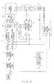
- FIG. 6 is a block diagram illustrating the entirety of the configuration of the prior art.
- a torque command generation unit 1 calculates a torque command value T CMD from a deviation between a velocity command value V c and a feedback velocity signal V CF .
- a current command generation unit 2 calculates, according to the torque command value T CMD , a q-axis current command value I qc and a d-axis current command value I dc , which are input to an armature current supplying apparatus 3.
- the armature current supplying apparatus 3 includes a power converter 3e, such as an inverter, from which three-phase output voltage is supplied to a synchronous motor M.
- the synchronous motor M has an encoder 6 attached thereto, and a rotor position signal ⁇ m is input to a feedback velocity signal generation unit 7 so as to generate the feedback velocity signal V cF .
- a current detector 4 is provided on the input side of the synchronous motor M, and current signals I u and I v of a U phase and V phase detected by the current detector 4 are input to an orthogonal two-axis transformation unit 5.
- the orthogonal two-axis transformation unit 5 converts the current signals I u and I v into a d-axis current feedback signal I dF and a q-axis current feedback signal I qF .
- current controllers 3a and 3b calculate a q-axis voltage command value V qC and a d-axis voltage command value V dC for eliminating a deviation between the current command value I qC and the feedback signal Iq F and a deviation between the current command value I dC and the feedback signal I dF .
- the voltage command values V qC and V dC are input to a coordinate converter 3c.
- the coordinate converter 3c converts the voltage command values V qC and V dC into a three-phase voltage command value V UC , V VC , V WC , and supplies the three-phase voltage value to a PWM controller 3d.
- the PWM controller 3d PWM-controls the power converter 3e using a drive signal generated from the voltage command value V UC , V VC , V WC and drives the synchronous motor M by converting a DC voltage into a three-phase AC voltage.
- an incorrect wiring detection unit 8 that detects incorrect two-phase wiring or incorrect three-phase wiring of the phase sequence of the synchronous motor M with respect to an output phase of the power converter 3e.
- the q-axis current command value I qC is in a saturated state
- the q-axis current feedback signal I qF becomes a predetermined value or higher
- the polarities of the q-axis current feedback signal I qF and feedback velocity signal V cF are reversed.
- the incorrect wiring detection unit 8 detects incorrect wiring and outputs an alarm signal AS.
- the incorrect wiring detection unit 8 consists of a saturated state determination unit 8a, a q-axis current feedback signal determination unit 8b, an integration unit 8c, and a determination unit 8d.
- the following will describe an operation of detecting two-phase incorrect wiring of a phase sequence performed by the incorrect wiring detection unit 8 (e.g., a situation in which an input phase of the synchronous motor M is connected in a phase sequence of U-W-V to an output phase U-V-W of the power converter 3e).
- the saturated state determination unit 8a determines that the q-axis current command value I qC has been put in a saturated state as depicted by (b) in FIG. 8 , and outputs the determination result to the integration unit 8c.
- the q-axis current feedback signal determinion unit 8b determines that the q-axis current feedback signal I qF is a predetermined value or higher, and outputs the determination result to the integration unit 8c.
- the integration unit 8c starts to integrate, as depicted by (a) and (c) in FIG.
- a period of time of a negative polarity of the feedback velocity signal V cF that oscillates without following the velocity command V c and outputs the integrated period as an integrated value IV.
- the determinion unit 8d outputs an alarm signal AS for reporting incorrect wiring.
- Patent document 1 does not describe an incorrect wiring detection method to be used when a plurality of motors are driven by a power converter, and is incapable of solving a problem that occurs when a plurality of motors include one with incorrect wiring, as described above.
- Patent document 1 to begin with, is directed to a synchronous motor and does not describe incorrect wiring of an induction motor.
- an object of the present invention is to provide a controlling apparatus for a power converter capable of detecting that a phase sequence of at least one of a plurality of induction motors parallely connected to each other and mechanically coupled to each other includes incorrect wiring, and an electric vehicle equipped with the controlling apparatus.
- a controlling apparatus is one for a power converter that operates a plurality of induction motors parallely connected to each other and mechanically coupled to each other by supplying to the induction motors a three-phase AC voltage obtained by converting a DC voltage through an operation of a semiconductor switching element, the controlling apparatus including: current detection means for detecting an output current of the power converter; current control means for generating a voltage command value to make a current detection value provided by the current detection means equal to a current command value; voltage command amplitude calculation means for calculating an amplitude of the voltage command value; storage means for storing, for each sampling period, a combination of a primary frequency of the induction motors and the amplitude of the voltage command value at that time; and gradient detection means for calculating, according to stored information from the storage means, a value that is an increase in the amplitude of the voltage command value that is divided by an increase in the primary frequency, and for outputting a failure signal upon determining, when the result of the division is less than
- a controlling apparatus is one for a power converter that operates a plurality of induction motors parallely connected to each other and mechanically coupled to each other by supplying to the induction motors a three-phase AC voltage obtained by converting a DC voltage through an operation of a semiconductor switching element, the controlling apparatus including: current detection means for detecting an output current of the power converter; voltage detection means for detecting an output voltage of the power converter; current control means for generating a voltage command value to make a current detection value provided by the current detection means equal to a current command value; voltage detection value amplitude calculation means for calculating an amplitude of a voltage detection value provided by the voltage detection means; storage means for storing, for each sampling period, a combination of a primary frequency of the induction motors and the amplitude of the voltage detection value at that time; and gradient detection means for calculating, according to stored information from the storage means, a value that is an increase in the amplitude of the voltage command value that is divided by an increase in the primary frequency, and for outputting a
- An electric vehicle according to claim 3 is a vehicle equipped with the controlling apparatus according to claim 1 or 2 and the power converter, wherein a plurality of wheel-driving induction motors are operated using the power converter.
- An electric vehicle according to claim 4 is the electric vehicle according to claim 3 wherein the gradient detection means outputs the failure signal when the vehicle is driven with a power-running notch of a lowest torque performance.
- An electric vehicle according to claim 5 is the electric vehicle according to claim 3 wherein the gradient detection means outputs the failure signal when the velocity of the vehicle is equal to or less than a predetermined value.
- An electric vehicle according to claim 6 is the electric vehicle according to claim 3 wherein the gradient detection means outputs the failure signal when the vehicle is driven with a power-running notch of a lowest torque performance at a velocity equal to or less than a predetermined value.
- the present invention can reliably detect that a plurality of induction motors parallely connected to each other and mechanically coupled to each other include at least one induction motor whose phase sequence includes incorrect wiring with respect to a power converter.
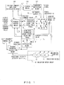
- FIG. 1 illustrates a drive system for an induction motor to which an embodiment of the invention is applied, wherein the drive system corresponds to an invention according to claim 1.
- a DC power supply 20 is connected to a power converter 10 such as an inverter; a DC voltage of the DC power supply 20 is converted into a three-phase AC voltage through operations of a semiconductor switching element within the power converter 10, and the three-phase AC voltage is supplied to an induction motor group 40.
- the induction motor group 40 consists of a plurality of (e. g. , four) induction motors 41 parallely connected to each other and mechanically coupled to each other.
- a control apparatus for the power converter 10 is configured as follows.
- primary frequency calculation means 50 sums a slip frequency (slip angular frequency) command value ⁇ se * and a rotational velocity detection value ⁇ re of the induction motor group 40, and a primary frequency (primary angular frequency) ⁇ 1 is generated.
- the primary frequency ⁇ 1 is integrated by integration means 60 so as to calculate an angle ⁇ required for vector control, and is also input to storage means 110.
- Current detection means 30 is provided on an output side of the power converter 10.
- a three-phase current detection value i u , i v , i w is input to coordinate conversion means 70.
- the coordinate conversion means 70 converts the current detection value i u , i v , i w into a d-axis current detection value i d and a q-axis current detection value i q , which are a two phase value, and outputs these values to current control means 90.
- the current control means 90 calculates and outputs a d-axis voltage command value V d * and q-axis voltage command value V q * for making the d-axis current detection value i d equal to a d-axis current command value i d * and for making the q-axis current detection value iq equal to a q-axis current command value i q *.
- the d-axis current command value i d * and the q-axis current command value i q * are supplied from a host controller (not illustrated).
- Coordinate conversion means 80 converts, according to the angle ⁇ , the d-axis voltage command value V d * and the q-axis voltage command value V q * into a three-phase voltage command value and supplies this value to the power converter 10. Through a switching operation of a semiconductor switching element, the power converter 10 generates and supplies a three-phase AC voltage conforming to the voltage command value to the induction motor group 40.
- the d-axis voltage command value V d * and q-axis voltage command value V q * output from the current control means 90 are also input to voltage command amplitude calculation means 100.
- the voltage command amplitude calculation means 100 calculates an amplitude v a * of the voltage command value in accordance with formula 1, and causes the storage means 110 to store this amplitude.
- v a * v d * 2 + v q * 2
- the storage means 110 stores the primary frequency ⁇ 1 and the amplitude v a * of the voltage command value, both of which have been sampled at certain intervals.
- the storage means 110 may store a combination of ⁇ 1 (k) and v a *(k), where ⁇ l1 (k) indicates a primary frequency obtained in a k-th sampling interval, and v a *(k) indicates the amplitude of the voltage command value.
- gradient detection means 120 determines the ratio of an increase in the amplitude of the voltage command value relative to an increase in the primary frequency ( ⁇ v a */ ⁇ 1 ) in accordance with formula 2.
- ⁇ v a * ⁇ 1 v a * k ⁇ v a * k ⁇ 1 ⁇ 1 k ⁇ ⁇ 1 k ⁇ 1 k ⁇ 1
- the gradient detection means 120 detects that the phase sequence of at least one induction motor 41 of the induction motor group 40 includes incorrect two-phase wiring with respect to an output phase of the power converter 10.
- the fact that a phase sequence of the induction motor group 40 includes incorrect two-phase wiring with respect to an output phase of the power converter 10 means, for example, that an input phase of an induction motor 41 is connected to an output phase U-V-W of the power converter 10 in a phase sequence of U-W-V.
- the gradient detection means 120 detects that a phase sequence of at least one induction motor 41 includes incorrect two-phase wiring with respect to an output phase of the power converter 10, the gradient detection means 120 generates and outputs a failure signal to the power converter 10. Upon receipt of the failure signal, the power converter 10 stops power supply to the induction motor group 40 by turning off all semiconductor switching elements (all gates are put in an off state).
- an analysis is made using a coordinate system that rotates at an output frequency (primary frequency) of a power converter (d-q axis coordinate system). Accordingly, an induction motor having an incorrect phase sequence of an input phase caused by two phases of a three-phase output of a power converter including incorrect wiring is analyzed on the assumption that a rotor side is equivalently rotating backward.
- a primary frequency ⁇ 1 of the induction motor is defined as positive
- the polarity of a rotational velocity ⁇ re is negative
- the polarity of a slip frequency is positive.
- Formula 3 expresses a relationship between ⁇ se2 , ⁇ re , and ⁇ 1 , where ⁇ se2 indicates a slip frequency of the induction motor with incorrect wiring, thereby clarifying that the slip frequency ⁇ se2 is about twice the rotational velocity ⁇ re .
- ⁇ se 2 ⁇ re + ⁇ 1
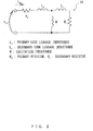
- FIG. 2 illustrates a T-shaped equivalent circuit of an induction motor 41.
- the T-shaped equivalent circuit is represented by a primary resistor R s , a primary-side leakage inductance L s , a secondary-side leakage inductance L r , an excitation inductance M, and a secondary resistor R r .
- a d-axis voltage v d and a q-axis voltage V q (represented as V dq in the figure) from a power converter can be considered to be applied to the induction motor 41 and the voltages can be considered to cause a d-axis current i d and a q-axis current iq (represented as i dq in the figure) to flow into the circuit.
- FIG. 3 illustrates an equivalent circuit with a plurality of induction motors 41 parallely connected to each other, as in FIG. 1 .
- Formula 4 expresses a voltage expression of an induction motor 41 in a complex vector format.
- v dq R s i dq + d dt ⁇ L s i dq + M L r ⁇ dq + j ⁇ 1 ⁇ L s i dq + j ⁇ 1 M L r ⁇ dq
- v dq indicates an applied voltage from the power converter 10; ⁇ dq , a secondary magnetic flux vector; i dq , a current vector; ⁇ 1 , a primary frequency; ⁇ L s , a leakage inductance (which is essentially equal to M/L r (L s +L r )).
- Formula 5 expresses a relationship between the dq-axis current i dq and inducted voltage e dq on a primary side, where e dq indicates an inducted voltage generated by the secondary magnetic flux ⁇ dq with voltage drops at the primary resistor R s and the leakage inductance ⁇ L s subtracted from the applied voltage v dq .
- Formula 5 expresses a relationship between the primary current i dq and the inducted voltage e dq .
- An impedance Z of a secondary side of the induction motor may be obtained by dividing both sides of formula 5 by the primary current i dq .
- FIG. 4 illustrates, under a condition in which the primary frequency has increased to 2.5[Hz]-10[Hz] (corresponding to a rotational velocity of 16[rad/s]-63[rad/s] of the induction motor), exemplary calculation of the magnitudes of respective secondary side impedances Z of one induction motor with correct wiring and an induction motor with an incorrect wiring in a phase sequence.
- a sum of the rotational velocity and the primary frequency is a slip frequency, as expressed by formula 3 described above. That is, when the slip frequency is fixed, the primary frequency decreases with an increase in the rotational velocity, and hence the secondary side impedance Z determined by formula 5 remains a low value even when the rotational velocity increases, as illustrated in FIG. 4 .
- FIG. 5 depicts a result of calculation of a composite impedance for a situation in which a plurality of (e.g., four) parallely connected induction motors are all in a correct wiring state with a correct phase sequence, and a result of calculation of a composite impedance for a situation in which the phase sequence of one of a plurality of induction motors is in an incorrect two-phase wiring state.
- the control apparatus for the power converter 10 performs current control and thus serves as a current source for a plurality of induction motors 41, as depicted in FIG. 3 .
- a current based on the same current command value flows through each induction motor 41, a voltage with an amplitude that is proportional to the magnitude of the composite impedance corresponding to either of the situations depicted in FIG. 5 will emerge at an output of the power converter 10.
- the storage means 110 stores the primary frequency ⁇ 1 and an amplitude v a * of the voltage command value, as depicted in FIG. 1 .
- the gradient detection means 120 detects the ratio ( ⁇ v a */ ⁇ 1 ) of an increase in the amplitude v a * of the voltage command value relative to an increase in the primary frequency ⁇ 1 (increase in the rotational velocity) in accordance with formula 2. According to the fact that the ratio has become less than a predetermined reference value, i.e., the fact that the degree of a change in composite impedance relative to the rotational velocity has become less than a predetermined reference value, incorrect wiring of the phase sequence of at least one induction motor 41 may be detected.
- a failure signal may be output from the gradient detection means 120 so as to perform an operation such as stopping the operation of the power converter 10.
- the amplitude of a voltage command value is used to detect incorrect wiring in the embodiments described above, but the amplitude of a voltage detection value may be used instead.
- the voltage detection means detects an output voltage from the power converter 10
- the voltage detection value amplitude calculation means which is a substitute for voltage command amplitude calculation means 100 depicted in FIG. 1 , calculates the amplitude of the voltage detection value.
- a combination of the amplitude of the voltage detection value and a primary frequency is stored in the storage means 110.
- the gradient detection means 120 calculates the ratio of an increase in the amplitude of the voltage detection value relative to an increase in the primary frequency, and incorrect wiring of the phase sequence of an induction motor 41 is detected when the ratio has become less than a predetermined reference value.
- the invention can be achieved as an electric vehicle wherein a plurality of wheel-driving induction motors are operated by a power converter such as one variable voltage variable frequency inverter (VVVF inverter) mounted on the vehicle.
- VVVF inverter variable voltage variable frequency inverter
- an electric device and wiring between devices may be removed from, and/or attached to, the vehicle.
- a running test may be conducted in which the electric vehicle is started with a power-running notch of one; the vehicle starts at a low velocity and is gradually accelerated. Owing to such a running test, it is possible to check that each electric device can be operated normally.
- a power-running notch of one is the power running notch of the lowest torque performance.
- an induction motor 41 when the invention is applied to an electric vehicle, it is preferable to detect incorrect wiring of an induction motor 41 while the vehicle is being driven with a power-running notch of one.
- An arrangement may be made such that incorrect wiring of the induction motor 41 is detected while the vehicle is being driven at a predetermined velocity (e.g., a maximum velocity the vehicle can achieve through acceleration with a power-running notch of one) or less.
- a predetermined velocity e.g., a maximum velocity the vehicle can achieve through acceleration with a power-running notch of one
- an arrangement may be made such that incorrect wiring of the induction motor 41 is detected while the vehicle is being driven with a power-running notch of one at a predetermined velocity or less.
- Such configurations allow incorrect wiring of the induction motor 41 to be detected in an early stage after the vehicle or electric devices are assembled.
Landscapes
- Engineering & Computer Science (AREA)
- Power Engineering (AREA)
- Transportation (AREA)
- Mechanical Engineering (AREA)
- Life Sciences & Earth Sciences (AREA)
- Sustainable Development (AREA)
- Sustainable Energy (AREA)
- Automation & Control Theory (AREA)
- Control Of Multiple Motors (AREA)
- Electric Propulsion And Braking For Vehicles (AREA)
- Control Of Ac Motors In General (AREA)
Abstract
A controlling apparatus for a power converter 10 such as an inverter that operates a plurality of induction motors 41 parallely connected to each other and mechanically coupled to each other includes: current detection means 30 for detecting an output current of the power converter 10; current control means 90 for generating a voltage command value to make the current detection value equal to a current command value; voltage command amplitude calculation means 100 for calculating an amplitude of the voltage command value; storage means 110 for storing, for each sampling period, a combination of a primary frequency of the induction motors 41 and the amplitude of the voltage command value at that time; and gradient detection means 120 for calculating, according to stored information from the storage means 110, a value that is an increase in the amplitude of the voltage command value that is divided by an increase in the primary frequency, and for outputting a failure signal upon determining, when a result of the division is less than a predetermined reference value, that the plurality of induction motors 41 include at least one induction motor 41 whose phase sequence includes incorrect wiring with respect to the power converter 10.
Description
- The present invention relates to a controlling apparatus for a power converter that includes a function to detect incorrect wiring of the phase sequence of at least one of a plurality of induction motors, and to an electric vehicle that includes the controlling apparatus, wherein the controlling apparatus is used in a system for driving the plurality of induction motors using one power converter.
-
Patent document 1 discloses a controlling apparatus for a three-phase synchronous motor that includes a incorrect wiring detecting function. -
FIG. 6 is a block diagram illustrating the entirety of the configuration of the prior art. InFIG. 6 , a torquecommand generation unit 1 calculates a torque command value TCMD from a deviation between a velocity command value Vc and a feedback velocity signal VCF. A currentcommand generation unit 2 calculates, according to the torque command value TCMD, a q-axis current command value Iqc and a d-axis current command value Idc, which are input to an armaturecurrent supplying apparatus 3. - The armature current supplying
apparatus 3 includes apower converter 3e, such as an inverter, from which three-phase output voltage is supplied to a synchronous motor M. The synchronous motor M has anencoder 6 attached thereto, and a rotor position signal θm is input to a feedback velocitysignal generation unit 7 so as to generate the feedback velocity signal VcF. - A
current detector 4 is provided on the input side of the synchronous motor M, and current signals Iu and Iv of a U phase and V phase detected by thecurrent detector 4 are input to an orthogonal two-axis transformation unit 5. Using a SIN signal and COS signal generated by asignal generator 9 according to the rotor position signal θm, the orthogonal two-axis transformation unit 5 converts the current signals Iu and Iv into a d-axis current feedback signal IdF and a q-axis current feedback signal IqF. - In the armature
current supplying apparatus 3,current controllers coordinate converter 3c. - Using the SIN signal and the COS signal, the
coordinate converter 3c converts the voltage command values VqC and VdC into a three-phase voltage command value VUC, VVC, VWC, and supplies the three-phase voltage value to aPWM controller 3d. - The
PWM controller 3d PWM-controls thepower converter 3e using a drive signal generated from the voltage command value VUC, VVC, VWC and drives the synchronous motor M by converting a DC voltage into a three-phase AC voltage. - In the prior art depicted in
FIG. 6 , an incorrectwiring detection unit 8 is provided that detects incorrect two-phase wiring or incorrect three-phase wiring of the phase sequence of the synchronous motor M with respect to an output phase of thepower converter 3e. In the presence of incorrect two-phase wiring or incorrect three-phase wiring, the q-axis current command value IqC is in a saturated state, the q-axis current feedback signal IqF becomes a predetermined value or higher, and the polarities of the q-axis current feedback signal IqF and feedback velocity signal VcF are reversed. By paying attention to these, the incorrectwiring detection unit 8 detects incorrect wiring and outputs an alarm signal AS. - As depicted in
FIG. 7 , the incorrectwiring detection unit 8 consists of a saturatedstate determination unit 8a, a q-axis current feedbacksignal determination unit 8b, anintegration unit 8c, and adetermination unit 8d. - With reference to
FIGS. 7 and8 , the following will describe an operation of detecting two-phase incorrect wiring of a phase sequence performed by the incorrect wiring detection unit 8 (e.g., a situation in which an input phase of the synchronous motor M is connected in a phase sequence of U-W-V to an output phase U-V-W of thepower converter 3e). - The saturated
state determination unit 8a determines that the q-axis current command value IqC has been put in a saturated state as depicted by (b) inFIG. 8 , and outputs the determination result to theintegration unit 8c. The q-axis current feedbacksignal determinion unit 8b determines that the q-axis current feedback signal IqF is a predetermined value or higher, and outputs the determination result to theintegration unit 8c. At a moment at which the q-axis current feedback signal IqF is determined to have a positive polarity, theintegration unit 8c starts to integrate, as depicted by (a) and (c) inFIG. 8 , a period of time of a negative polarity of the feedback velocity signal VcF that oscillates without following the velocity command Vc, and outputs the integrated period as an integrated value IV. As depicted by (c) and (d) inFIG. 8 , at a moment at which the integrated value IV reaches a cumulative time RT, thedeterminion unit 8d outputs an alarm signal AS for reporting incorrect wiring. -
- Patent document 1:
Japanese Laid-open Patent Publication No. 2010-213557 - Patent document 2:
Japanese Laid-open Patent Publication No. 2000-032616 - Patent document 3:
Japanese Laid-open Patent Publication No. 2008-253008 - Patent document 4:
Japanese Laid-open Patent Publication No. 9-016233 - Patent document 5:
Japanese Laid-open Patent Publication No. 2007-318955 - However, in a case where a plurality of induction motors parallely connected to each other and mechanically coupled to each other are driven by one power converter, even if a phase sequence of one motor includes incorrect wiring, the motor in the wrong-wiring state will be driven due to the influence of output torque of the motors with correct wiring. As a result, a load velocity becomes adjustable in conformity with a command value. Accordingly, a prior art relying on velocity and/or velocity command values is inapplicable to a plurality of induction motors.
- The prior art described in
patent document 1 does not describe an incorrect wiring detection method to be used when a plurality of motors are driven by a power converter, and is incapable of solving a problem that occurs when a plurality of motors include one with incorrect wiring, as described above.Patent document 1, to begin with, is directed to a synchronous motor and does not describe incorrect wiring of an induction motor. - Accordingly, an object of the present invention is to provide a controlling apparatus for a power converter capable of detecting that a phase sequence of at least one of a plurality of induction motors parallely connected to each other and mechanically coupled to each other includes incorrect wiring, and an electric vehicle equipped with the controlling apparatus.
- To solve the problem, a controlling apparatus according to
claim 1 is one for a power converter that operates a plurality of induction motors parallely connected to each other and mechanically coupled to each other by supplying to the induction motors a three-phase AC voltage obtained by converting a DC voltage through an operation of a semiconductor switching element, the controlling apparatus including: current detection means for detecting an output current of the power converter; current control means for generating a voltage command value to make a current detection value provided by the current detection means equal to a current command value; voltage command amplitude calculation means for calculating an amplitude of the voltage command value; storage means for storing, for each sampling period, a combination of a primary frequency of the induction motors and the amplitude of the voltage command value at that time; and gradient detection means for calculating, according to stored information from the storage means, a value that is an increase in the amplitude of the voltage command value that is divided by an increase in the primary frequency, and for outputting a failure signal upon determining, when the result of the division is less than a predetermined reference value, that the plurality of induction motors include at least one induction motor whose phase sequence includes incorrect wiring with respect to the power converter. - A controlling apparatus according to
claim 2 is one for a power converter that operates a plurality of induction motors parallely connected to each other and mechanically coupled to each other by supplying to the induction motors a three-phase AC voltage obtained by converting a DC voltage through an operation of a semiconductor switching element, the controlling apparatus including: current detection means for detecting an output current of the power converter; voltage detection means for detecting an output voltage of the power converter; current control means for generating a voltage command value to make a current detection value provided by the current detection means equal to a current command value; voltage detection value amplitude calculation means for calculating an amplitude of a voltage detection value provided by the voltage detection means; storage means for storing, for each sampling period, a combination of a primary frequency of the induction motors and the amplitude of the voltage detection value at that time; and gradient detection means for calculating, according to stored information from the storage means, a value that is an increase in the amplitude of the voltage command value that is divided by an increase in the primary frequency, and for outputting a failure signal upon determining, when the result of the division is less than a predetermined reference value, that the plurality of induction motors include at least one induction motor whose phase sequence includes incorrect wiring with respect to the power converter. - An electric vehicle according to
claim 3 is a vehicle equipped with the controlling apparatus according toclaim - An electric vehicle according to
claim 4 is the electric vehicle according toclaim 3 wherein the gradient detection means outputs the failure signal when the vehicle is driven with a power-running notch of a lowest torque performance. - An electric vehicle according to
claim 5 is the electric vehicle according toclaim 3 wherein the gradient detection means outputs the failure signal when the velocity of the vehicle is equal to or less than a predetermined value. - An electric vehicle according to
claim 6 is the electric vehicle according toclaim 3 wherein the gradient detection means outputs the failure signal when the vehicle is driven with a power-running notch of a lowest torque performance at a velocity equal to or less than a predetermined value. - According to the ratio of an increase in an amplitude of a voltage command value or voltage detection value relative to an increase in a primary frequency, the present invention can reliably detect that a plurality of induction motors parallely connected to each other and mechanically coupled to each other include at least one induction motor whose phase sequence includes incorrect wiring with respect to a power converter.
-
-
FIG. 1 is a block diagram illustrating a drive system for an induction motor to which an embodiment of the invention is applied; -
FIG. 2 illustrates a T-shaped equivalent circuit of an induction motor; -
FIG. 3 illustrates an equivalent circuit with a plurality of induction motors parallely connected; -
FIG. 4 illustrates a comparison in exemplary calculation of the magnitude of a secondary side impedance between an induction motor in a correct wiring state and the induction motor in an incorrect wiring state; -
FIG. 5 illustrates a comparison in exemplary calculation of the magnitude of a composite impedance of a plurality of induction motors between the plurality of induction motors in a correct wiring state and the plurality of induction motors in an incorrect wiring state; -
FIG. 6 is a block diagram of a prior art described inpatent document 1; -
FIG. 7 is a block diagram illustrating the configuration of an incorrect wiring detection unit inFIG. 6 ; and -
FIG. 8 is an operation explanatory diagram of the incorrect wiring detection unit inFIG. 6 . - The following will describe embodiments of the invention with reference to the drawings.
-
FIG. 1 illustrates a drive system for an induction motor to which an embodiment of the invention is applied, wherein the drive system corresponds to an invention according toclaim 1. InFIG. 1 , aDC power supply 20 is connected to apower converter 10 such as an inverter; a DC voltage of theDC power supply 20 is converted into a three-phase AC voltage through operations of a semiconductor switching element within thepower converter 10, and the three-phase AC voltage is supplied to aninduction motor group 40. - The
induction motor group 40 consists of a plurality of (e. g. , four)induction motors 41 parallely connected to each other and mechanically coupled to each other. - A control apparatus for the
power converter 10 is configured as follows. - In particular, primary frequency calculation means 50 sums a slip frequency (slip angular frequency) command value ωse* and a rotational velocity detection value ωre of the
induction motor group 40, and a primary frequency (primary angular frequency) ω1 is generated. The primary frequency ω1 is integrated by integration means 60 so as to calculate an angle θ required for vector control, and is also input to storage means 110. - Current detection means 30 is provided on an output side of the
power converter 10. A three-phase current detection value iu, iv, iw is input to coordinate conversion means 70. According to the angle θ, the coordinate conversion means 70 converts the current detection value iu, iv, iw into a d-axis current detection value id and a q-axis current detection value iq, which are a two phase value, and outputs these values to current control means 90. - The current control means 90 calculates and outputs a d-axis voltage command value Vd* and q-axis voltage command value Vq* for making the d-axis current detection value id equal to a d-axis current command value id* and for making the q-axis current detection value iq equal to a q-axis current command value iq*. The d-axis current command value id* and the q-axis current command value iq* are supplied from a host controller (not illustrated).
- Coordinate conversion means 80 converts, according to the angle θ, the d-axis voltage command value Vd* and the q-axis voltage command value Vq* into a three-phase voltage command value and supplies this value to the
power converter 10. Through a switching operation of a semiconductor switching element, thepower converter 10 generates and supplies a three-phase AC voltage conforming to the voltage command value to theinduction motor group 40. - The d-axis voltage command value Vd* and q-axis voltage command value Vq* output from the current control means 90 are also input to voltage command amplitude calculation means 100. The voltage command amplitude calculation means 100 calculates an amplitude va* of the voltage command value in accordance with
formula 1, and causes the storage means 110 to store this amplitude.
- The storage means 110 stores the primary frequency ω1 and the amplitude va* of the voltage command value, both of which have been sampled at certain intervals. For example, the storage means 110 may store a combination of ω1(k) and va*(k), where ωl1(k) indicates a primary frequency obtained in a k-th sampling interval, and va*(k) indicates the amplitude of the voltage command value.
- Using ω1(k) and va*(k), i.e., the newly obtained data obtained in the k-th interval, and ω1(k-1) and va*(k-1), i.e., previous data, gradient detection means 120 determines the ratio of an increase in the amplitude of the voltage command value relative to an increase in the primary frequency (Δva*/Δω1) in accordance with
formula 2.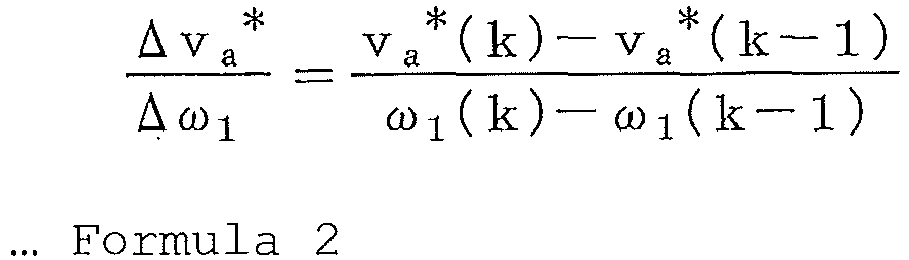
- When the ratio (Δva*/Δω1) is less than a predetermined reference value, the gradient detection means 120 detects that the phase sequence of at least one
induction motor 41 of theinduction motor group 40 includes incorrect two-phase wiring with respect to an output phase of thepower converter 10. The fact that a phase sequence of theinduction motor group 40 includes incorrect two-phase wiring with respect to an output phase of thepower converter 10 means, for example, that an input phase of aninduction motor 41 is connected to an output phase U-V-W of thepower converter 10 in a phase sequence of U-W-V. When the gradient detection means 120 detects that a phase sequence of at least oneinduction motor 41 includes incorrect two-phase wiring with respect to an output phase of thepower converter 10, the gradient detection means 120 generates and outputs a failure signal to thepower converter 10. Upon receipt of the failure signal, thepower converter 10 stops power supply to theinduction motor group 40 by turning off all semiconductor switching elements (all gates are put in an off state). - Next, with reference to the configuration depicted in
FIG. 1 , descriptions will be given of the reason why incorrect two-phase wiring of aninduction motor 41 can be detected. - In vector control of an induction motor, an analysis is made using a coordinate system that rotates at an output frequency (primary frequency) of a power converter (d-q axis coordinate system). Accordingly, an induction motor having an incorrect phase sequence of an input phase caused by two phases of a three-phase output of a power converter including incorrect wiring is analyzed on the assumption that a rotor side is equivalently rotating backward. In this case, when the polarity of a primary frequency ω1 of the induction motor is defined as positive, the polarity of a rotational velocity ωre is negative, and the polarity of a slip frequency is positive.
Formula 3 expresses a relationship between ωse2, ωre, and ω1, where ωse2 indicates a slip frequency of the induction motor with incorrect wiring, thereby clarifying that the slip frequency ωse2 is about twice the rotational velocity ωre.
-
FIG. 2 illustrates a T-shaped equivalent circuit of aninduction motor 41. The T-shaped equivalent circuit is represented by a primary resistor Rs, a primary-side leakage inductance Ls, a secondary-side leakage inductance Lr, an excitation inductance M, and a secondary resistor Rr. As illustrated, a d-axis voltage vd and a q-axis voltage Vq (represented as Vdq in the figure) from a power converter can be considered to be applied to theinduction motor 41 and the voltages can be considered to cause a d-axis current id and a q-axis current iq (represented as idq in the figure) to flow into the circuit. - Meanwhile,
FIG. 3 illustrates an equivalent circuit with a plurality ofinduction motors 41 parallely connected to each other, as inFIG. 1 . -
Formula 4 expresses a voltage expression of aninduction motor 41 in a complex vector format.
- In
formula 4, vdq indicates an applied voltage from thepower converter 10; ϕdq, a secondary magnetic flux vector; idq, a current vector; ω1, a primary frequency; σLs, a leakage inductance (which is essentially equal to M/Lr (Ls+Lr)). -
Formula 5 expresses a relationship between the dq-axis current idq and inducted voltage edq on a primary side, where edq indicates an inducted voltage generated by the secondary magnetic flux ϕdq with voltage drops at the primary resistor Rs and the leakage inductance σLs subtracted from the applied voltage vdq. Informula 5, a derivative term is ignored, and a steady state is taken into consideration.
-
Formula 5 expresses a relationship between the primary current idq and the inducted voltage edq. An impedance Z of a secondary side of the induction motor may be obtained by dividing both sides offormula 5 by the primary current idq. -
FIG. 4 illustrates, under a condition in which the primary frequency has increased to 2.5[Hz]-10[Hz] (corresponding to a rotational velocity of 16[rad/s]-63[rad/s] of the induction motor), exemplary calculation of the magnitudes of respective secondary side impedances Z of one induction motor with correct wiring and an induction motor with an incorrect wiring in a phase sequence. A rated voltage of 200[V] and a rated output of 7.5[kW], i.e., constants of an induction motor for vector control, are used as motor constants. - In the induction motor with incorrect wiring in a phase sequence, a sum of the rotational velocity and the primary frequency is a slip frequency, as expressed by
formula 3 described above. That is, when the slip frequency is fixed, the primary frequency decreases with an increase in the rotational velocity, and hence the secondary side impedance Z determined byformula 5 remains a low value even when the rotational velocity increases, as illustrated inFIG. 4 . - In regard to the magnitude of the composite impedance of the entirety of the induction motor, the secondary side impedance becomes dominant with an increase in the primary frequency.
FIG. 5 depicts a result of calculation of a composite impedance for a situation in which a plurality of (e.g., four) parallely connected induction motors are all in a correct wiring state with a correct phase sequence, and a result of calculation of a composite impedance for a situation in which the phase sequence of one of a plurality of induction motors is in an incorrect two-phase wiring state. - According to
FIG. 5 , in comparison with a situation in which all induction motors are in a correct wiring state, when an induction motor includes incorrect wiring, including an induction motor with incorrect wiring leads to a decreased slope of the composite impedance relative to the rotational velocity. - Meanwhile, the control apparatus for the
power converter 10 performs current control and thus serves as a current source for a plurality ofinduction motors 41, as depicted inFIG. 3 . Hence, when a current based on the same current command value flows through eachinduction motor 41, a voltage with an amplitude that is proportional to the magnitude of the composite impedance corresponding to either of the situations depicted inFIG. 5 will emerge at an output of thepower converter 10. - Accordingly, the storage means 110 stores the primary frequency ω1 and an amplitude va* of the voltage command value, as depicted in
FIG. 1 . The gradient detection means 120 detects the ratio (Δva*/Δω1) of an increase in the amplitude va* of the voltage command value relative to an increase in the primary frequency ω1 (increase in the rotational velocity) in accordance withformula 2. According to the fact that the ratio has become less than a predetermined reference value, i.e., the fact that the degree of a change in composite impedance relative to the rotational velocity has become less than a predetermined reference value, incorrect wiring of the phase sequence of at least oneinduction motor 41 may be detected. - As described above, when incorrect wiring of an
induction motor 41 is detected, a failure signal may be output from the gradient detection means 120 so as to perform an operation such as stopping the operation of thepower converter 10. - The amplitude of a voltage command value is used to detect incorrect wiring in the embodiments described above, but the amplitude of a voltage detection value may be used instead. In particular, although not illustrated, as described in
claim 2, the voltage detection means detects an output voltage from thepower converter 10, and the voltage detection value amplitude calculation means, which is a substitute for voltage command amplitude calculation means 100 depicted inFIG. 1 , calculates the amplitude of the voltage detection value. In addition, a combination of the amplitude of the voltage detection value and a primary frequency is stored in the storage means 110. - The gradient detection means 120 calculates the ratio of an increase in the amplitude of the voltage detection value relative to an increase in the primary frequency, and incorrect wiring of the phase sequence of an
induction motor 41 is detected when the ratio has become less than a predetermined reference value. - The invention can be achieved as an electric vehicle wherein a plurality of wheel-driving induction motors are operated by a power converter such as one variable voltage variable frequency inverter (VVVF inverter) mounted on the vehicle.
- During assembly, maintenance, or inspection of the electric vehicle, an electric device and wiring between devices may be removed from, and/or attached to, the vehicle. After the vehicle or electric devices are assembled, a running test may be conducted in which the electric vehicle is started with a power-running notch of one; the vehicle starts at a low velocity and is gradually accelerated. Owing to such a running test, it is possible to check that each electric device can be operated normally. A power-running notch of one is the power running notch of the lowest torque performance.
- Accordingly, when the invention is applied to an electric vehicle, it is preferable to detect incorrect wiring of an
induction motor 41 while the vehicle is being driven with a power-running notch of one. An arrangement may be made such that incorrect wiring of theinduction motor 41 is detected while the vehicle is being driven at a predetermined velocity (e.g., a maximum velocity the vehicle can achieve through acceleration with a power-running notch of one) or less. In addition, an arrangement may be made such that incorrect wiring of theinduction motor 41 is detected while the vehicle is being driven with a power-running notch of one at a predetermined velocity or less. - Such configurations allow incorrect wiring of the
induction motor 41 to be detected in an early stage after the vehicle or electric devices are assembled.
Claims (6)
- A controlling apparatus for a power converter that operates a plurality of induction motors parallely connected to each other and mechanically coupled to each other by supplying to the induction motors a three-phase AC voltage obtained by converting a DC voltage through an operation of a semiconductor switching element, the controlling apparatus comprising:current detection means for detecting an output current of the power converter;current control means for generating a voltage command value to make a current detection value provided by the current detection means equal to a current command value;voltage command amplitude calculation means for calculating an amplitude of the voltage command value;storage means for storing, for each sampling period, a combination of a primary frequency of the induction motors and the amplitude of the voltage command value at that time; andgradient detection means for calculating, according to stored information from the storage means, a value that is an increase in the amplitude of the voltage command value that is divided by an increase in the primary frequency, and for outputting a failure signal upon determining, when a result of the division is less than a predetermined reference value, that the plurality of induction motors include at least one induction motor whose phase sequence includes incorrect wiring with respect to the power converter.
- A controlling apparatus for a power converter that operates a plurality of induction motors parallely connected to each other and mechanically coupled to each other by supplying to the induction motors a three-phase AC voltage obtained by converting a DC voltage through an operation of a semiconductor switching element, the controlling apparatus comprising:current detection means for detecting an output current of the power converter;voltage detection means for detecting an output voltage of the power converter;current control means for generating a voltage command value to make a current detection value provided by the current detection means equal to a current command value;voltage detection value amplitude calculation means for calculating an amplitude of a voltage detection value provided by the voltage detection means;storage means for storing, for each sampling period, a combination of a primary frequency of the induction motors and the amplitude of the voltage command value at that time; andgradient detection means for calculating, according to stored information from the storage means, a value that is an increase in the amplitude of the voltage command value that is divided by an increase in the primary frequency, and for outputting a failure signal upon determining, when a result of the division is less than a predetermined reference value, that the plurality of induction motors include at least one induction motor whose phase sequence includes incorrect wiring with respect to the power converter.
- An electric vehicle, wherein
the vehicle is equipped with the controlling apparatus according to claim 1 or 2 and the power converter, and
a plurality of wheel-driving induction motors are operated using the power converter. - The electric vehicle according to claim 3, wherein
the gradient detection means outputs the failure signal when the vehicle is driven with a power-running notch of a lowest torque performance. - The electric vehicle according to claim 3, wherein
the gradient detection means outputs the failure signal when a velocity of the vehicle is equal to or less than a predetermined value. - The electric vehicle according to claim 3, wherein
the gradient detection means outputs the failure signal when the vehicle is driven with a power-running notch of a lowest torque performance at a velocity equal to or less than a predetermined value.
Applications Claiming Priority (2)
| Application Number | Priority Date | Filing Date | Title |
|---|---|---|---|
| JP2013263143A JP6159659B2 (en) | 2013-12-20 | 2013-12-20 | Power converter control device and electric vehicle |
| PCT/JP2014/076560 WO2015093128A1 (en) | 2013-12-20 | 2014-10-03 | Electric vehicle and device for controlling power converter |
Publications (1)
| Publication Number | Publication Date |
|---|---|
| EP3086465A1 true EP3086465A1 (en) | 2016-10-26 |
Family
ID=53402485
Family Applications (1)
| Application Number | Title | Priority Date | Filing Date |
|---|---|---|---|
| EP14871585.7A Withdrawn EP3086465A1 (en) | 2013-12-20 | 2014-10-03 | Electric vehicle and device for controlling power converter |
Country Status (7)
| Country | Link |
|---|---|
| US (1) | US9654031B2 (en) |
| EP (1) | EP3086465A1 (en) |
| JP (1) | JP6159659B2 (en) |
| KR (1) | KR20160084856A (en) |
| CN (1) | CN105814789A (en) |
| TW (1) | TWI646769B (en) |
| WO (1) | WO2015093128A1 (en) |
Cited By (1)
| Publication number | Priority date | Publication date | Assignee | Title |
|---|---|---|---|---|
| WO2019096359A1 (en) * | 2017-11-20 | 2019-05-23 | Linak A/S | Determining an electrical current flowing in one of a plurality of electric motors |
Families Citing this family (7)
| Publication number | Priority date | Publication date | Assignee | Title |
|---|---|---|---|---|
| JP6533132B2 (en) * | 2015-09-14 | 2019-06-19 | 株式会社日立製作所 | Control device of electric car |
| JP6725298B2 (en) * | 2016-04-04 | 2020-07-15 | 東海旅客鉄道株式会社 | Electric power conversion control device for trains |
| WO2018042672A1 (en) * | 2016-09-05 | 2018-03-08 | 三菱電機株式会社 | Motor control device |
| US10625758B2 (en) * | 2017-01-31 | 2020-04-21 | Central Japan Railway Company | Railroad vehicle, voltage estimating device for power supply line, and method for estimating voltage of power supply line |
| WO2018203393A1 (en) * | 2017-05-02 | 2018-11-08 | 三菱電機株式会社 | Control device for motor, and electric power steering system |
| DE112017008316T5 (en) * | 2017-12-28 | 2020-09-17 | Mitsubishi Electric Corporation | ELECTRIC VEHICLE CONTROL DEVICE |
| CN114073001B (en) * | 2019-07-09 | 2024-07-02 | 株式会社安川电机 | Power conversion device, pressure-feed device, power conversion method, program product, diagnostic device, and diagnostic method |
Family Cites Families (13)
| Publication number | Priority date | Publication date | Assignee | Title |
|---|---|---|---|---|
| JP2839199B2 (en) * | 1990-03-13 | 1998-12-16 | 株式会社日立製作所 | Induction motor control device |
| JP3625901B2 (en) | 1995-06-30 | 2005-03-02 | 三菱電機株式会社 | Method and apparatus for automatically optimizing servo control system |
| JP2000032616A (en) * | 1998-07-08 | 2000-01-28 | Toyota Motor Corp | Motor misconnection detection device |
| US6737828B2 (en) * | 2001-07-19 | 2004-05-18 | Matsushita Electric Industrial Co., Ltd. | Washing machine motor drive device |
| JP4774975B2 (en) * | 2005-12-15 | 2011-09-21 | トヨタ自動車株式会社 | Electric motor control device |
| JP2007318955A (en) | 2006-05-29 | 2007-12-06 | Nidec-Shimpo Corp | Driving method and driving controller of electric motor |
| JP2008253008A (en) | 2007-03-29 | 2008-10-16 | Mitsubishi Electric Corp | Power conversion device and power supply misconnection determination method |
| JP2009005478A (en) * | 2007-06-21 | 2009-01-08 | Toyo Electric Mfg Co Ltd | Induction machine controller |
| RU2431916C1 (en) * | 2007-09-27 | 2011-10-20 | Мицубиси Электрик Корпорейшн | Controller of rotary electric machine |
| JP5331523B2 (en) | 2009-03-12 | 2013-10-30 | 山洋電気株式会社 | Control device for three-phase synchronous motor with erroneous wiring detection function |
| JP5164030B2 (en) | 2011-06-14 | 2013-03-13 | 株式会社安川電機 | Multi-axis motor drive system and multi-axis motor drive apparatus |
| JP5959349B2 (en) * | 2012-07-18 | 2016-08-02 | 株式会社東芝 | Electric vehicle control device and vehicle drive system |
| JP6082316B2 (en) * | 2013-05-27 | 2017-02-15 | 東洋電機製造株式会社 | Induction motor controller |
-
2013
- 2013-12-20 JP JP2013263143A patent/JP6159659B2/en active Active
-
2014
- 2014-10-03 CN CN201480066964.4A patent/CN105814789A/en active Pending
- 2014-10-03 WO PCT/JP2014/076560 patent/WO2015093128A1/en not_active Ceased
- 2014-10-03 KR KR1020167015113A patent/KR20160084856A/en not_active Abandoned
- 2014-10-03 EP EP14871585.7A patent/EP3086465A1/en not_active Withdrawn
- 2014-10-21 TW TW103136292A patent/TWI646769B/en active
-
2016
- 2016-06-08 US US15/177,338 patent/US9654031B2/en not_active Expired - Fee Related
Cited By (1)
| Publication number | Priority date | Publication date | Assignee | Title |
|---|---|---|---|---|
| WO2019096359A1 (en) * | 2017-11-20 | 2019-05-23 | Linak A/S | Determining an electrical current flowing in one of a plurality of electric motors |
Also Published As
| Publication number | Publication date |
|---|---|
| JP6159659B2 (en) | 2017-07-05 |
| KR20160084856A (en) | 2016-07-14 |
| JP2015119600A (en) | 2015-06-25 |
| US9654031B2 (en) | 2017-05-16 |
| WO2015093128A1 (en) | 2015-06-25 |
| TW201531008A (en) | 2015-08-01 |
| TWI646769B (en) | 2019-01-01 |
| US20160285395A1 (en) | 2016-09-29 |
| CN105814789A (en) | 2016-07-27 |
Similar Documents
| Publication | Publication Date | Title |
|---|---|---|
| EP3086465A1 (en) | Electric vehicle and device for controlling power converter | |
| EP2757670B1 (en) | Method and apparatus for controlling power converter with inverter output filter | |
| US8575879B2 (en) | Methods, systems and apparatus for controlling a multi-phase inverter | |
| US7759888B2 (en) | AC motor controller | |
| KR100440166B1 (en) | Resolver phase cablibration system of electric vehicle and method thereof | |
| KR101622011B1 (en) | Method and apparatus for controlling of 3-phase ac motor | |
| EP1401093A2 (en) | Position-sensorless motor control method and apparatus | |
| US20030020429A1 (en) | Motor controller | |
| EP3252942A1 (en) | Inverter control device and motor drive system | |
| US9590551B2 (en) | Control apparatus for AC motor | |
| US9419555B2 (en) | Synchronous machine control apparatus | |
| EP2963804B1 (en) | Inverter device, construction machine, and motor control method | |
| EP3214754B1 (en) | Motor control device | |
| EP2621079B1 (en) | Inverter control device and inverter control method | |
| JP2002233180A (en) | Power converter | |
| CN101208857A (en) | Operate three-phase equipment with single-phase power | |
| EP3396846A1 (en) | Method for controlling medium-voltage inverter and system comprising the same | |
| US11396236B2 (en) | Electric vehicle control device | |
| CN101471622B (en) | Apparatus for controlling inverter | |
| KR100319943B1 (en) | Pole position detection apparatus for synchronous motor | |
| EP2860870A1 (en) | A method for starting a sensorless permanent magnet motor | |
| EP3435539A1 (en) | Power conversion device and power conversion method |
Legal Events
| Date | Code | Title | Description |
|---|---|---|---|
| PUAI | Public reference made under article 153(3) epc to a published international application that has entered the european phase |
Free format text: ORIGINAL CODE: 0009012 |
|
| 17P | Request for examination filed |
Effective date: 20160720 |
|
| AK | Designated contracting states |
Kind code of ref document: A1 Designated state(s): AL AT BE BG CH CY CZ DE DK EE ES FI FR GB GR HR HU IE IS IT LI LT LU LV MC MK MT NL NO PL PT RO RS SE SI SK SM TR |
|
| AX | Request for extension of the european patent |
Extension state: BA ME |
|
| DAX | Request for extension of the european patent (deleted) | ||
| STAA | Information on the status of an ep patent application or granted ep patent |
Free format text: STATUS: THE APPLICATION HAS BEEN WITHDRAWN |
|
| 18W | Application withdrawn |
Effective date: 20170828 |