EP3086451A1 - Motor, cradle head using motor, and photographing apparatus using cradle head - Google Patents
Motor, cradle head using motor, and photographing apparatus using cradle head Download PDFInfo
- Publication number
- EP3086451A1 EP3086451A1 EP14883771.9A EP14883771A EP3086451A1 EP 3086451 A1 EP3086451 A1 EP 3086451A1 EP 14883771 A EP14883771 A EP 14883771A EP 3086451 A1 EP3086451 A1 EP 3086451A1
- Authority
- EP
- European Patent Office
- Prior art keywords
- motor
- rotating member
- magnet
- gimbal
- fixed
- Prior art date
- Legal status (The legal status is an assumption and is not a legal conclusion. Google has not performed a legal analysis and makes no representation as to the accuracy of the status listed.)
- Granted
Links
Images


Classifications
-
- G—PHYSICS
- G03—PHOTOGRAPHY; CINEMATOGRAPHY; ANALOGOUS TECHNIQUES USING WAVES OTHER THAN OPTICAL WAVES; ELECTROGRAPHY; HOLOGRAPHY
- G03B—APPARATUS OR ARRANGEMENTS FOR TAKING PHOTOGRAPHS OR FOR PROJECTING OR VIEWING THEM; APPARATUS OR ARRANGEMENTS EMPLOYING ANALOGOUS TECHNIQUES USING WAVES OTHER THAN OPTICAL WAVES; ACCESSORIES THEREFOR
- G03B17/00—Details of cameras or camera bodies; Accessories therefor
- G03B17/56—Accessories
- G03B17/561—Support related camera accessories
-
- F—MECHANICAL ENGINEERING; LIGHTING; HEATING; WEAPONS; BLASTING
- F16—ENGINEERING ELEMENTS AND UNITS; GENERAL MEASURES FOR PRODUCING AND MAINTAINING EFFECTIVE FUNCTIONING OF MACHINES OR INSTALLATIONS; THERMAL INSULATION IN GENERAL
- F16M—FRAMES, CASINGS OR BEDS OF ENGINES, MACHINES OR APPARATUS, NOT SPECIFIC TO ENGINES, MACHINES OR APPARATUS PROVIDED FOR ELSEWHERE; STANDS; SUPPORTS
- F16M11/00—Stands or trestles as supports for apparatus or articles placed thereon ; Stands for scientific apparatus such as gravitational force meters
- F16M11/02—Heads
- F16M11/04—Means for attachment of apparatus; Means allowing adjustment of the apparatus relatively to the stand
- F16M11/06—Means for attachment of apparatus; Means allowing adjustment of the apparatus relatively to the stand allowing pivoting
-
- F—MECHANICAL ENGINEERING; LIGHTING; HEATING; WEAPONS; BLASTING
- F16—ENGINEERING ELEMENTS AND UNITS; GENERAL MEASURES FOR PRODUCING AND MAINTAINING EFFECTIVE FUNCTIONING OF MACHINES OR INSTALLATIONS; THERMAL INSULATION IN GENERAL
- F16M—FRAMES, CASINGS OR BEDS OF ENGINES, MACHINES OR APPARATUS, NOT SPECIFIC TO ENGINES, MACHINES OR APPARATUS PROVIDED FOR ELSEWHERE; STANDS; SUPPORTS
- F16M11/00—Stands or trestles as supports for apparatus or articles placed thereon ; Stands for scientific apparatus such as gravitational force meters
- F16M11/02—Heads
- F16M11/18—Heads with mechanism for moving the apparatus relatively to the stand
-
- H—ELECTRICITY
- H02—GENERATION; CONVERSION OR DISTRIBUTION OF ELECTRIC POWER
- H02K—DYNAMO-ELECTRIC MACHINES
- H02K1/00—Details of the magnetic circuit
- H02K1/06—Details of the magnetic circuit characterised by the shape, form or construction
- H02K1/22—Rotating parts of the magnetic circuit
- H02K1/27—Rotor cores with permanent magnets
-
- H—ELECTRICITY
- H02—GENERATION; CONVERSION OR DISTRIBUTION OF ELECTRIC POWER
- H02K—DYNAMO-ELECTRIC MACHINES
- H02K11/00—Structural association of dynamo-electric machines with electric components or with devices for shielding, monitoring or protection
- H02K11/20—Structural association of dynamo-electric machines with electric components or with devices for shielding, monitoring or protection for measuring, monitoring, testing, protecting or switching
- H02K11/21—Devices for sensing speed or position, or actuated thereby
- H02K11/215—Magnetic effect devices, e.g. Hall-effect or magneto-resistive elements
-
- H—ELECTRICITY
- H02—GENERATION; CONVERSION OR DISTRIBUTION OF ELECTRIC POWER
- H02K—DYNAMO-ELECTRIC MACHINES
- H02K29/00—Motors or generators having non-mechanical commutating devices, e.g. discharge tubes or semiconductor devices
- H02K29/06—Motors or generators having non-mechanical commutating devices, e.g. discharge tubes or semiconductor devices with position sensing devices
- H02K29/08—Motors or generators having non-mechanical commutating devices, e.g. discharge tubes or semiconductor devices with position sensing devices using magnetic effect devices, e.g. Hall-plates, magneto-resistors
-
- H—ELECTRICITY
- H04—ELECTRIC COMMUNICATION TECHNIQUE
- H04N—PICTORIAL COMMUNICATION, e.g. TELEVISION
- H04N23/00—Cameras or camera modules comprising electronic image sensors; Control thereof
- H04N23/60—Control of cameras or camera modules
- H04N23/68—Control of cameras or camera modules for stable pick-up of the scene, e.g. compensating for camera body vibrations
- H04N23/682—Vibration or motion blur correction
- H04N23/685—Vibration or motion blur correction performed by mechanical compensation
- H04N23/687—Vibration or motion blur correction performed by mechanical compensation by shifting the lens or sensor position
-
- F—MECHANICAL ENGINEERING; LIGHTING; HEATING; WEAPONS; BLASTING
- F16—ENGINEERING ELEMENTS AND UNITS; GENERAL MEASURES FOR PRODUCING AND MAINTAINING EFFECTIVE FUNCTIONING OF MACHINES OR INSTALLATIONS; THERMAL INSULATION IN GENERAL
- F16M—FRAMES, CASINGS OR BEDS OF ENGINES, MACHINES OR APPARATUS, NOT SPECIFIC TO ENGINES, MACHINES OR APPARATUS PROVIDED FOR ELSEWHERE; STANDS; SUPPORTS
- F16M2200/00—Details of stands or supports
- F16M2200/04—Balancing means
- F16M2200/041—Balancing means for balancing rotational movement of the head
Definitions
- the present invention relates to a motor, a gimbal having the motor and an image capturing device having the gimbal.
- An image capturing device generally comprises a gimbal and an image capturing apparatus carried on the gimbal.
- the gimbal is configured to fix the image capturing device, freely adjust an attitude of the image capturing apparatus (e.g., changing an elevation and/or orientation of the image capturing apparatus) and stably maintain the image capturing apparatus at a determined attitude to achieve a stable, smooth and multi-angle image capturing.
- the image capturing apparatus may be a camcorder or a camera.
- the gimbal comprises a motor.
- the motor is provided with a stator, a rotor and a sensor for sensing relative positions of the rotor with respect to the stator of the motor.
- the prior art sensor generally includes an encoder and a potentiometer, where the encoder has a high precision but a large volume, a high cost and a certain frictional resistance, and the potentiometer has a low precision but a greater frictional resistance, which significantly affects the controlling of the gimbal. Both sensors are contact type sensors, resulting in a great frictional resistance and poor electrical contact.
- An object of the invention is to provide a motor having a low frictional resistance, a gimbal having the motor, and an image capturing device having the gimbal.
- a motor may comprise a stator, a rotator rotatably connected with the stator, and an electrical connecting device for providing an electric signal for the motor.
- the motor may further comprise a magnet fixed on the rotator, and a Hall angular displacement sensor fixed on the electrical connecting devices and arranged opposite to the magnet. The magnet and the Hall angular displacement sensor may be spaced from each other by the electrical connecting devices.
- a gimbal may comprise a first rotating member, a second rotating member rotatably connected with the first rotating member, and a motor configured to drive the second rotating member to rotate with respect to the first rotating member.
- the motor may comprise a stator, a rotator rotatably connected with the stator, and an electrical connecting device for providing an electric signal to the motor.
- the motor further comprises a magnet fixed on the rotator, and a Hall angular displacement sensor fixed on the electrical connecting device and arranged opposite to the magnet. The magnet and the Hall angular displacement sensor may be spaced from each other by the electrical connecting device.
- an image capturing device may comprise a gimbal and a payload carried on the gimbal.
- the gimbal may comprise a first rotating member, a second rotating member rotatably connected with the first rotating member, and a motor configured to drive the second rotating member to rotate with respect to the first rotating member.
- the motor may comprise a stator, a rotator rotatably connected with the stator, and an electrical connecting device configured to provide an electric signal to the motor.
- the motor may further comprise a magnet fixed on the rotator, and a Hall angular displacement sensor fixed on the electrical connecting device and arranged opposite to the magnet. The magnet and the Hall angular displacement sensor may be spaced from each other by the device.
- a method of detecting a positional relationship between the stator and the rotator by a non-contact Hall angular displacement sensor is provided in the present invention, which solves the great frictional resistance problem in conventional detection methods.
- the image capturing device in embodiments of the present invention may be used as an auxiliary device for photographing, image capturing, monitoring and sampling, and can be carried on an air-based vehicle (e.g., a rotor wing aircraft or a fixed wing aircraft), a water-based vehicle (e.g., a submarine or a ship), a road-based vehicle (e.g., an automobile) or a space-based vehicle (e.g., a satellite, a space station, or a spaceship) and the like.
- the image capturing device may comprise a gimbal and a payload carried on the gimbal.
- the gimbal may be configured to fix the payload, freely adjust an attitude of the payload (e.g., to change an elevation, an inclination angle and/or an orientation of the payload), and stably maintain the carried payload at a determined attitude.
- the payload may be an image capturing device such as a camera or a camcorder. Alternatively, the payload may also be a sensor or the like. In this embodiment, the image capturing device may be carried by an aircraft.
- the payload may be an interchangeable lens digital camera (ILDC), a surveillance camera or the like.
- ILDC interchangeable lens digital camera
- an image capturing device 100 may comprise a gimbal 10 and a payload 20 carried on the gimbal 10.
- the gimbal 10 comprises a first rotating member 1, a second rotating member 2 rotatably connected with one end of the first rotating member 1 and being configured to carry the payload 20, and a motor 30 connecting the first rotating member 1 with the second rotating member 2.
- the payload 20 is a camera.
- the motor 30 is configured to drive the second rotating member 2 to rotate with respect to the first rotating member 1.
- the motor 30 comprises a stator 31 fixed on the first rotating member 1, a rotator 32 rotatably connected with the stator 31 and fixed on the second rotating member 2, an electrical connecting device 33 fixed on the first rotating member 1 and providing an electric signal to the stator 31, a magnet 34 fixed on the rotator 32 and a Hall angular displacement sensor 35 fixed on the electrical connecting device 33 and arranged opposite to the magnet 34.
- the magnet 34 and the Hall angular displacement sensor 35 may operate together to detect relative positions of the rotator 32 with respect to the stator 31 of the motor 30.
- the magnet 34 and the Hall angular displacement sensor 35 are spaced from each other by the electrical connecting device 33.
- the rotator 32 comprises a rotating shaft assembly 36 rotatably connected with the stator 31 and a rotor 37 fixed on the rotating shaft assembly 36.
- the rotor 37 is received in the second rotating member 2.
- the stator 31 is a coil
- the rotor 37 is a magnet that generates a magnetic force with the stator 31.
- the stator 31 may be a magnet
- the rotor 37 may be a coil.
- the rotating shaft assembly 36 comprises a rotating shaft 38, and an upper bearing 381 and a low bearing 382 sleeved respectively on two ends of the rotating shaft 38.
- One end of the rotating shaft 38 is received in the first rotating member 1, and the other end is received in the second rotating member 2.
- the upper bearing 381 is received in the first rotating member 1.
- the lower bearing 382 is received in the second rotating member 2.
- the rotating shaft assembly 36 rotatably connects the first rotating member 1 with the second rotating member 2 through the rotor 37 and the stator 31.
- the magnet 34 is fixed on the rotating shaft 38 and arranged to face the electrical connecting device 33 which is received in the first rotating member 1.
- the electrical connecting device 33 may be a printed circuit board (PCB) or a flexible circuit board.
- the electrical connecting device 33 comprises a first surface 331 and a second surface 332 opposite to the first surface 331.
- the Hall angular displacement sensor 35 may be fixed on the first surface 331, and the magnet 34 is arranged opposite to the second surface 332, such that the magnet 34 does not come into contact with the Hall angular displacement sensor 35.
- the Hall angular displacement sensor 35 senses a positional relationship between the stator 31 and the rotator 32, the Hall angular displacement sensor 35 has a small volume; therefore the problem of great frictional resistance of conventional detection modes can be solved.
- the magnet 34 is fixedly connected with the rotator 32, and the electric connecting devices 33 provided with the Hall angular displacement sensor 35 is fixedly connected with the stator 31.
- the Hall angular displacement sensor 35 detects a rotational angle of the rotor 37 with respect to the stator 31, forming an angular displacement sensing manner which is of a non-contact type but has an effect equivalent to that of an absolute position encoder.
- the working resistance of the gimbal 10 is effectively reduced, and the response of the gimbal 10 is increased.
- stator 31 may be fixed directly on the first rotating member 1
- rotator 32 may be fixed directly on the second rotating member 2, such that the stator 31 and the rotator 32 may be embedded directly into internal space of the first rotating member 1 and the second rotating member 2 and integrated with the first rotating member 1 and the second rotating member 2, effectively reducing an overall size of the gimbal 10 .
Landscapes
- Engineering & Computer Science (AREA)
- General Engineering & Computer Science (AREA)
- Power Engineering (AREA)
- Mechanical Engineering (AREA)
- Microelectronics & Electronic Packaging (AREA)
- Physics & Mathematics (AREA)
- General Physics & Mathematics (AREA)
- Multimedia (AREA)
- Signal Processing (AREA)
- Studio Devices (AREA)
- Accessories Of Cameras (AREA)
- Brushless Motors (AREA)
Abstract
Description
- The present invention relates to a motor, a gimbal having the motor and an image capturing device having the gimbal.
- An image capturing device generally comprises a gimbal and an image capturing apparatus carried on the gimbal. The gimbal is configured to fix the image capturing device, freely adjust an attitude of the image capturing apparatus (e.g., changing an elevation and/or orientation of the image capturing apparatus) and stably maintain the image capturing apparatus at a determined attitude to achieve a stable, smooth and multi-angle image capturing. The image capturing apparatus may be a camcorder or a camera.
- The gimbal comprises a motor. The motor is provided with a stator, a rotor and a sensor for sensing relative positions of the rotor with respect to the stator of the motor. The prior art sensor generally includes an encoder and a potentiometer, where the encoder has a high precision but a large volume, a high cost and a certain frictional resistance, and the potentiometer has a low precision but a greater frictional resistance, which significantly affects the controlling of the gimbal. Both sensors are contact type sensors, resulting in a great frictional resistance and poor electrical contact.
- An object of the invention is to provide a motor having a low frictional resistance, a gimbal having the motor, and an image capturing device having the gimbal.
- The aforementioned object may be achieved by various embodiments of the invention.
- In some embodiments, a motor may comprise a stator, a rotator rotatably connected with the stator, and an electrical connecting device for providing an electric signal for the motor. The motor may further comprise a magnet fixed on the rotator, and a Hall angular displacement sensor fixed on the electrical connecting devices and arranged opposite to the magnet. The magnet and the Hall angular displacement sensor may be spaced from each other by the electrical connecting devices.
- In some embodiments, a gimbal may comprise a first rotating member, a second rotating member rotatably connected with the first rotating member, and a motor configured to drive the second rotating member to rotate with respect to the first rotating member. The motor may comprise a stator, a rotator rotatably connected with the stator, and an electrical connecting device for providing an electric signal to the motor. The motor further comprises a magnet fixed on the rotator, and a Hall angular displacement sensor fixed on the electrical connecting device and arranged opposite to the magnet. The magnet and the Hall angular displacement sensor may be spaced from each other by the electrical connecting device.
- In some embodiments, an image capturing device may comprise a gimbal and a payload carried on the gimbal. The gimbal may comprise a first rotating member, a second rotating member rotatably connected with the first rotating member, and a motor configured to drive the second rotating member to rotate with respect to the first rotating member. The motor may comprise a stator, a rotator rotatably connected with the stator, and an electrical connecting device configured to provide an electric signal to the motor. The motor may further comprise a magnet fixed on the rotator, and a Hall angular displacement sensor fixed on the electrical connecting device and arranged opposite to the magnet. The magnet and the Hall angular displacement sensor may be spaced from each other by the device.
- As compared with the prior art, a method of detecting a positional relationship between the stator and the rotator by a non-contact Hall angular displacement sensor is provided in the present invention, which solves the great frictional resistance problem in conventional detection methods.
-
-
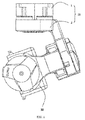
FIG. 1 is a perspective view of an image capturing device according to the invention. -
FIG. 2 is a perspective view of the image capturing device from which the carried payload is removed according to the invention. -
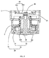
FIG.3 is a sectional view ofFIG. 2 along the III-III line. -
FIG. 4 is a perspective view ofFIG. 2 from another angle of view, from which the first rotating member is partially omitted. - The image capturing device in embodiments of the present invention may be used as an auxiliary device for photographing, image capturing, monitoring and sampling, and can be carried on an air-based vehicle (e.g., a rotor wing aircraft or a fixed wing aircraft), a water-based vehicle (e.g., a submarine or a ship), a road-based vehicle (e.g., an automobile) or a space-based vehicle (e.g., a satellite, a space station, or a spaceship) and the like. The image capturing device may comprise a gimbal and a payload carried on the gimbal. The gimbal may be configured to fix the payload, freely adjust an attitude of the payload (e.g., to change an elevation, an inclination angle and/or an orientation of the payload), and stably maintain the carried payload at a determined attitude. The payload may be an image capturing device such as a camera or a camcorder. Alternatively, the payload may also be a sensor or the like. In this embodiment, the image capturing device may be carried by an aircraft. The payload may be an interchangeable lens digital camera (ILDC), a surveillance camera or the like. The image capturing device according to the present invention will be described below in detail with reference to the accompanying drawings.
- As illustrated in
FIG. 1 to FIG. 4 , in some embodiments of the invention, an image capturing device 100 may comprise agimbal 10 and apayload 20 carried on thegimbal 10. Thegimbal 10 comprises a first rotatingmember 1, a second rotatingmember 2 rotatably connected with one end of the first rotatingmember 1 and being configured to carry thepayload 20, and amotor 30 connecting the first rotatingmember 1 with the second rotatingmember 2. In this embodiment, thepayload 20 is a camera. Themotor 30 is configured to drive the second rotatingmember 2 to rotate with respect to the first rotatingmember 1. - The
motor 30 comprises astator 31 fixed on the first rotatingmember 1, arotator 32 rotatably connected with thestator 31 and fixed on the second rotatingmember 2, anelectrical connecting device 33 fixed on the first rotatingmember 1 and providing an electric signal to thestator 31, amagnet 34 fixed on therotator 32 and a Hallangular displacement sensor 35 fixed on theelectrical connecting device 33 and arranged opposite to themagnet 34. Themagnet 34 and the Hallangular displacement sensor 35 may operate together to detect relative positions of therotator 32 with respect to thestator 31 of themotor 30. Themagnet 34 and the Hallangular displacement sensor 35 are spaced from each other by theelectrical connecting device 33. - The
rotator 32 comprises a rotatingshaft assembly 36 rotatably connected with thestator 31 and arotor 37 fixed on the rotatingshaft assembly 36. Therotor 37 is received in the second rotatingmember 2. In this embodiment, thestator 31 is a coil, and therotor 37 is a magnet that generates a magnetic force with thestator 31. In an alternative embodiment, thestator 31 may be a magnet, and therotor 37 may be a coil. - The rotating
shaft assembly 36 comprises a rotatingshaft 38, and anupper bearing 381 and a low bearing 382 sleeved respectively on two ends of the rotatingshaft 38. One end of the rotatingshaft 38 is received in the first rotatingmember 1, and the other end is received in the second rotatingmember 2. The upper bearing 381 is received in the first rotatingmember 1. Thelower bearing 382 is received in the second rotatingmember 2. The rotatingshaft assembly 36 rotatably connects the first rotatingmember 1 with the second rotatingmember 2 through therotor 37 and thestator 31. Themagnet 34 is fixed on the rotatingshaft 38 and arranged to face the electrical connectingdevice 33 which is received in the first rotatingmember 1. - The
electrical connecting device 33 may be a printed circuit board (PCB) or a flexible circuit board. Theelectrical connecting device 33 comprises afirst surface 331 and asecond surface 332 opposite to thefirst surface 331. The Hallangular displacement sensor 35 may be fixed on thefirst surface 331, and themagnet 34 is arranged opposite to thesecond surface 332, such that themagnet 34 does not come into contact with the Hallangular displacement sensor 35. When the Hallangular displacement sensor 35 senses a positional relationship between thestator 31 and therotator 32, the Hallangular displacement sensor 35 has a small volume; therefore the problem of great frictional resistance of conventional detection modes can be solved. - In some embodiments, in the image capturing device 100, the
magnet 34 is fixedly connected with therotator 32, and theelectric connecting devices 33 provided with the Hallangular displacement sensor 35 is fixedly connected with thestator 31. The Hallangular displacement sensor 35 detects a rotational angle of therotor 37 with respect to thestator 31, forming an angular displacement sensing manner which is of a non-contact type but has an effect equivalent to that of an absolute position encoder. The working resistance of thegimbal 10 is effectively reduced, and the response of thegimbal 10 is increased. - Furthermore, the
stator 31 may be fixed directly on the first rotatingmember 1, and therotator 32 may be fixed directly on the second rotatingmember 2, such that thestator 31 and therotator 32 may be embedded directly into internal space of the first rotatingmember 1 and the second rotatingmember 2 and integrated with the first rotatingmember 1 and the second rotatingmember 2, effectively reducing an overall size of thegimbal 10. - The foregoing disclosure is merely illustrative of preferred embodiments of the invention, and the protection scope of the invention is not limited thereto. Any equivalent modifications or variations made by those of ordinary skill in the art according to the disclosure of the invention shall fall into the protection scope as defined in the appended claims.
Claims (10)
- A motor comprising a stator, a rotator rotatably connected with the stator and an electrical connecting device configured to provide an electric signal to the motor; wherein the motor further comprises: a magnet fixed on the rotator, and a Hall angular displacement sensor fixed on the electrical connecting device and arranged opposite to the magnet, the magnet and the Hall angular displacement sensor are spaced from each other by the electrical connecting device.
- The motor of claim 1, wherein the rotator comprises a rotating shaft assembly rotatably connected with the stator, and a rotor fixed on the rotating shaft assembly, the magnet is fixed on the rotating shaft assembly.
- The motor of claim 2, wherein the rotating shaft assembly comprises a rotating shaft, an upper bearing and a low bearing sleeved respectively on two ends of the rotating shaft, the magnet is fixed on the rotating shaft.
- The motor of claim 1, wherein the electrical connecting device comprises a first surface and a second surface opposite to the first surface, the Hall angular displacement sensor is fixedly arranged on the first surface, the magnet is arranged opposite to the second surface, the magnet is out of contact with the Hall angular displacement sensor.
- The motor of claim 1, wherein the electrical connecting device is a PCB board or a flexible circuit board.
- A gimbal comprising a first rotating member and a second rotating member rotatably connected with the first rotating member, wherein the gimbal further comprises: a motor of any of claims 1 to 5, the motor is configured to drive the second rotating member to rotate with respect to the first rotating member.
- The gimbal of claim 6, wherein the stator is fixed on the first rotating member, and the rotator is fixed on the second rotating member.
- An image capturing device, wherein the image capturing device comprising the gimbal of claim 6 and a payload carried on the gimbal.
- The image capturing device of claim 8, wherein the payload is connected with the second rotating member.
- The image capturing device of claim 8, wherein the payload is a camera.
Applications Claiming Priority (2)
| Application Number | Priority Date | Filing Date | Title |
|---|---|---|---|
| CN201410070502.1A CN103825408A (en) | 2014-02-28 | 2014-02-28 | Motor, cloud deck using the motor and shooting device using the cloud deck |
| PCT/CN2014/081613 WO2015127741A1 (en) | 2014-02-28 | 2014-07-03 | Motor, cradle head using motor, and photographing apparatus using cradle head |
Publications (3)
| Publication Number | Publication Date |
|---|---|
| EP3086451A1 true EP3086451A1 (en) | 2016-10-26 |
| EP3086451A4 EP3086451A4 (en) | 2017-02-15 |
| EP3086451B1 EP3086451B1 (en) | 2021-06-09 |
Family
ID=50760317
Family Applications (1)
| Application Number | Title | Priority Date | Filing Date |
|---|---|---|---|
| EP14883771.9A Active EP3086451B1 (en) | 2014-02-28 | 2014-07-03 | Motor, cradle head using motor, and photographing apparatus using cradle head |
Country Status (5)
| Country | Link |
|---|---|
| US (3) | US10488739B2 (en) |
| EP (1) | EP3086451B1 (en) |
| JP (1) | JP6228669B2 (en) |
| CN (1) | CN103825408A (en) |
| WO (1) | WO2015127741A1 (en) |
Cited By (2)
| Publication number | Priority date | Publication date | Assignee | Title |
|---|---|---|---|---|
| EP3355450A4 (en) * | 2015-10-26 | 2018-10-24 | Autel Robotics Co., Ltd. | Motor, pan-tilt, and aircraft |
| US10488739B2 (en) | 2014-02-28 | 2019-11-26 | Sz Dji Osom Technology Co., Ltd. | Motor, gimbal having the motor, and image capturing device having the gimbal |
Families Citing this family (29)
| Publication number | Priority date | Publication date | Assignee | Title |
|---|---|---|---|---|
| CN104756373B (en) * | 2014-06-30 | 2018-06-05 | 深圳市大疆灵眸科技有限公司 | Horizontal stage electric machine and holder |
| WO2016004568A1 (en) * | 2014-07-07 | 2016-01-14 | 深圳市大疆创新科技有限公司 | Limiting device and aircraft using same |
| CN104158378A (en) * | 2014-08-25 | 2014-11-19 | 广州虹天航空科技有限公司 | Motor module and stabilizer with same |
| CN105518370B (en) * | 2014-10-31 | 2018-02-02 | 深圳市大疆灵眸科技有限公司 | The roll axis assembly and the gimbal it uses |
| CN104656664B (en) * | 2015-02-16 | 2017-07-11 | 南京航空航天大学 | Vehicle-mounted many rotor unmanned helicopter approaching and landing system control systems and guiding control method |
| WO2017028021A1 (en) * | 2015-08-14 | 2017-02-23 | SZ DJI Technology Co., Ltd. | System and method for supporting compact servo system |
| CN205781776U (en) * | 2016-05-17 | 2016-12-07 | 零度智控(北京)智能科技有限公司 | The Cloud Terrace and the filming apparatus of this The Cloud Terrace of application |
| CN105667818A (en) * | 2016-01-05 | 2016-06-15 | 零度智控(北京)智能科技有限公司 | Cradle head |
| CN108496300B (en) | 2016-02-22 | 2022-05-27 | 深圳市大疆灵眸科技有限公司 | Motor position sensing |
| CN105584637A (en) * | 2016-02-26 | 2016-05-18 | 深圳市哈博森科技有限公司 | Servo assembly for aerial camera stability-increasing cradle head and stability-increasing cradle head with same |
| CN105576902B (en) * | 2016-03-07 | 2018-02-06 | 南京艾驰电子科技有限公司 | Flexible PG board of motor |
| CN105782657B (en) * | 2016-03-10 | 2019-03-12 | 深圳英飞拓科技股份有限公司 | Holder and its photographic device |
| CN110912341B (en) | 2016-03-30 | 2022-03-18 | 米沃奇电动工具公司 | Brushless motor for electric tool |
| CN107390456B (en) * | 2016-05-17 | 2020-03-20 | 天津远度科技有限公司 | Cradle head winding method |
| CN107690745B (en) * | 2016-10-27 | 2019-08-27 | 深圳市大疆灵眸科技有限公司 | Motor, head and shooting equipment |
| US20180003340A1 (en) * | 2017-01-23 | 2018-01-04 | Haoxiang Electric Energy (Kunshan) Co., Ltd. | Two-axis gimbal and three-axis gimbal |
| EP3419146B1 (en) * | 2017-04-11 | 2022-08-10 | Guilin Zhishen Information Technology Co., Ltd. | Motor housing |
| US10737774B2 (en) | 2018-01-05 | 2020-08-11 | Gopro, Inc. | Unmanned aerial vehicle propeller assembly |
| US10462369B2 (en) | 2018-01-05 | 2019-10-29 | Gopro, Inc. | Routing of transmission media through rotatable components |
| KR102490560B1 (en) | 2018-01-16 | 2023-01-19 | 엘지이노텍 주식회사 | 3-axis rotating apparatus mounted on a flying object |
| CN109286745A (en) * | 2018-11-23 | 2019-01-29 | 中山联合光电科技股份有限公司 | The electromagnetic drive type photographic device of adjustable direction |
| USD914794S1 (en) * | 2019-04-12 | 2021-03-30 | SZ DJI Technology Co., Ltd. | Gimbal with handle |
| CN110579224B (en) * | 2019-11-11 | 2020-03-31 | 宁波韦尔德斯凯勒智能科技有限公司 | A method and system for accurately measuring the displacement of a motor mover using a Hall sensor |
| CN113692512A (en) * | 2020-08-26 | 2021-11-23 | 深圳市大疆创新科技有限公司 | Cloud platform |
| CN112815827A (en) * | 2020-12-25 | 2021-05-18 | 武汉航空仪表有限责任公司 | Angular displacement measuring device and method based on Hall effect |
| KR20220093614A (en) * | 2020-12-28 | 2022-07-05 | 엘지이노텍 주식회사 | Motor Position Detection Device |
| JP7264931B2 (en) | 2021-03-25 | 2023-04-25 | キヤノンプレシジョン株式会社 | Gimbal and system with same |
| CN112866540B (en) * | 2021-03-30 | 2025-08-08 | 江西晶浩光学有限公司 | Camera module, camera module installation method and terminal device |
| KR102902606B1 (en) * | 2023-06-15 | 2025-12-18 | (주)니어스랩 | Mission equipment mounting device to improve control performance |
Family Cites Families (29)
| Publication number | Priority date | Publication date | Assignee | Title |
|---|---|---|---|---|
| US6462443B2 (en) * | 2001-01-18 | 2002-10-08 | Sunonwealth Electric Machine Industry Co., Ltd. | Brushless D.C. motors structure |
| FR2830139B1 (en) * | 2001-09-26 | 2004-08-27 | Roulements Soc Nouvelle | PULSE CONTROLLED ELECTRONICALLY SWITCHED DEVICE |
| JP3799270B2 (en) * | 2001-12-21 | 2006-07-19 | 株式会社日立製作所 | Control device for switching the driving state of an automobile |
| US7905463B2 (en) * | 2004-12-13 | 2011-03-15 | Optical Alchemy, Inc. | Multiple axis gimbal employing nested spherical shells |
| TWI329403B (en) | 2005-04-19 | 2010-08-21 | Sunonwealth Electr Mach Ind Co | Rotor balance structure for motor |
| EP1816729B1 (en) * | 2006-02-03 | 2015-10-21 | ebm-papst St. Georgen GmbH & Co. KG | Electric motor |
| CN200987089Y (en) | 2006-10-11 | 2007-12-05 | 咸宁市三六电机制造有限公司 | Permanent-magnet brushless DC motor for electrical excursion vehicle |
| KR100903519B1 (en) | 2007-09-18 | 2009-06-19 | 주식회사 아모텍 | Permanent magnet embedded motor and air suction device using same |
| JP5369433B2 (en) | 2007-12-21 | 2013-12-18 | パナソニック株式会社 | motor |
| CN201185382Y (en) | 2008-04-25 | 2009-01-21 | 陈炎平 | Permanent magnet DC brushless motor for changing rail of electrified railroad |
| JP2010039350A (en) | 2008-08-07 | 2010-02-18 | Tamagawa Seiki Co Ltd | Structure for adjusting weight balance of space stabilizing device |
| CN201315525Y (en) | 2008-11-18 | 2009-09-23 | 张泽洪 | Signal acquiring and controlling device for low-speed motor |
| JP2010136588A (en) * | 2008-12-08 | 2010-06-17 | Mitsuba Corp | Actuator |
| CN102349218B (en) * | 2009-03-11 | 2014-01-29 | 香港中文大学 | Multifunctional magneto-rheological driving mechanism |
| JP5063722B2 (en) * | 2010-03-19 | 2012-10-31 | 三菱電機株式会社 | Electric drive device and electric power steering device equipped with the same |
| DE112011101281B4 (en) | 2010-04-12 | 2022-03-03 | Schaeffler Technologies AG & Co. KG | hydrostatic actuator |
| CN201830125U (en) | 2010-10-30 | 2011-05-11 | 中山大洋电机股份有限公司 | A brushless DC motor structure induced by Hall elements |
| JP2012147519A (en) * | 2011-01-07 | 2012-08-02 | Mitsuba Corp | Motor device |
| JP5427842B2 (en) * | 2011-06-30 | 2014-02-26 | 日立オートモティブシステムズ株式会社 | Rotation angle measuring device, control device, and rotating machine system using them |
| JP2013090532A (en) | 2011-10-21 | 2013-05-13 | Mitsuba Corp | Brushless motor |
| CN102545524B (en) | 2012-02-14 | 2013-11-20 | 美的威灵电机技术(上海)有限公司 | Rotor position detection device for permanent magnet motor |
| CN202647109U (en) * | 2012-06-04 | 2013-01-02 | 深圳市大疆创新科技有限公司 | Electric adjusting device, and holder and aircraft with same |
| KR101940683B1 (en) | 2012-06-22 | 2019-04-12 | 엘지이노텍 주식회사 | Motor |
| CN103547133B (en) * | 2012-07-17 | 2016-12-21 | 上海捷能汽车技术有限公司 | Integrated board-like anti-EMI materials and preparation method thereof |
| CN104704717B (en) * | 2012-10-01 | 2017-10-24 | 三菱电机株式会社 | electric drive |
| JP5850259B2 (en) * | 2012-11-28 | 2016-02-03 | 株式会社デンソー | Rotating electric machine |
| KR20150032117A (en) * | 2013-09-17 | 2015-03-25 | 삼성전자주식회사 | Stepping motor and System thereof |
| CN103825408A (en) | 2014-02-28 | 2014-05-28 | 深圳市大疆创新科技有限公司 | Motor, cloud deck using the motor and shooting device using the cloud deck |
| CN203722420U (en) * | 2014-02-28 | 2014-07-16 | 深圳市大疆创新科技有限公司 | Motor, holder applying motor and shooting device applying holder |
-
2014
- 2014-02-28 CN CN201410070502.1A patent/CN103825408A/en active Pending
- 2014-07-03 WO PCT/CN2014/081613 patent/WO2015127741A1/en not_active Ceased
- 2014-07-03 JP JP2016526167A patent/JP6228669B2/en not_active Expired - Fee Related
- 2014-07-03 EP EP14883771.9A patent/EP3086451B1/en active Active
- 2014-07-03 US US15/115,422 patent/US10488739B2/en active Active
-
2019
- 2019-11-22 US US16/692,447 patent/US11106118B2/en active Active
-
2021
- 2021-08-30 US US17/461,375 patent/US20210389647A1/en not_active Abandoned
Cited By (4)
| Publication number | Priority date | Publication date | Assignee | Title |
|---|---|---|---|---|
| US10488739B2 (en) | 2014-02-28 | 2019-11-26 | Sz Dji Osom Technology Co., Ltd. | Motor, gimbal having the motor, and image capturing device having the gimbal |
| US11106118B2 (en) | 2014-02-28 | 2021-08-31 | Sz Dji Osmo Technology Co., Ltd. | Motor, gimbal having the motor, and image capturing device having the gimbal |
| EP3355450A4 (en) * | 2015-10-26 | 2018-10-24 | Autel Robotics Co., Ltd. | Motor, pan-tilt, and aircraft |
| US10298848B2 (en) | 2015-10-26 | 2019-05-21 | Autel Robotics Co., Ltd. | Motor, gimbal and aircraft |
Also Published As
| Publication number | Publication date |
|---|---|
| US20170176840A1 (en) | 2017-06-22 |
| WO2015127741A1 (en) | 2015-09-03 |
| EP3086451B1 (en) | 2021-06-09 |
| JP2017501667A (en) | 2017-01-12 |
| CN103825408A (en) | 2014-05-28 |
| US11106118B2 (en) | 2021-08-31 |
| US10488739B2 (en) | 2019-11-26 |
| US20200089086A1 (en) | 2020-03-19 |
| EP3086451A4 (en) | 2017-02-15 |
| US20210389647A1 (en) | 2021-12-16 |
| JP6228669B2 (en) | 2017-11-08 |
Similar Documents
| Publication | Publication Date | Title |
|---|---|---|
| US11106118B2 (en) | Motor, gimbal having the motor, and image capturing device having the gimbal | |
| US11605998B2 (en) | Bearing configuration for an electronic motor | |
| TWI622339B (en) | Payload mounting platform | |
| CN108496300B (en) | Motor position sensing | |
| CN107872180B (en) | Method and device for detecting position of motor rotor and electronic equipment | |
| EP3127819B1 (en) | Tripod head driving device and tripod head assembly using same | |
| CN108235702A (en) | A kind of holder, unmanned plane and its control method | |
| CN107111322A (en) | Cloud platform, operation method, control method thereof, and mobile device using same | |
| US10053230B2 (en) | Magnetic levitation obstacle avoidance device and magnetic levitation holder | |
| JP2017508999A (en) | Pan head, image forming apparatus using the head, and drone | |
| EP3400171B1 (en) | Multirotor aircraft | |
| JP6286667B2 (en) | Lens barrel and imaging device | |
| CN106155105A (en) | Device for controlling holder and holder system | |
| CN109665099A (en) | Stringing camera chain and stringing method for imaging | |
| JP2018100498A (en) | Floating inspection device | |
| CN206202711U (en) | A kind of head and unmanned plane | |
| CN110869787A (en) | Magnetic sensor calibration method and movable platform | |
| CN203722420U (en) | Motor, holder applying motor and shooting device applying holder | |
| CN104076825B (en) | Driving device, carrier for application of driving device and control method thereof | |
| CN112739621A (en) | Cloud platform and unmanned vehicles | |
| KR102358694B1 (en) | Gimbal device and flying device | |
| JP6922370B2 (en) | Aircraft |
Legal Events
| Date | Code | Title | Description |
|---|---|---|---|
| PUAI | Public reference made under article 153(3) epc to a published international application that has entered the european phase |
Free format text: ORIGINAL CODE: 0009012 |
|
| 17P | Request for examination filed |
Effective date: 20160718 |
|
| AK | Designated contracting states |
Kind code of ref document: A1 Designated state(s): AL AT BE BG CH CY CZ DE DK EE ES FI FR GB GR HR HU IE IS IT LI LT LU LV MC MK MT NL NO PL PT RO RS SE SI SK SM TR |
|
| AX | Request for extension of the european patent |
Extension state: BA ME |
|
| A4 | Supplementary search report drawn up and despatched |
Effective date: 20170116 |
|
| RIC1 | Information provided on ipc code assigned before grant |
Ipc: H02K 11/00 20160101ALI20170110BHEP Ipc: F16M 11/06 20060101ALI20170110BHEP Ipc: H02K 29/08 20060101AFI20170110BHEP Ipc: F16M 11/18 20060101ALI20170110BHEP Ipc: G03B 17/56 20060101ALI20170110BHEP |
|
| DAX | Request for extension of the european patent (deleted) | ||
| RAP1 | Party data changed (applicant data changed or rights of an application transferred) |
Owner name: SZ DJI OSMO TECHNOLOGY CO., LTD. |
|
| STAA | Information on the status of an ep patent application or granted ep patent |
Free format text: STATUS: EXAMINATION IS IN PROGRESS |
|
| 17Q | First examination report despatched |
Effective date: 20191204 |
|
| GRAP | Despatch of communication of intention to grant a patent |
Free format text: ORIGINAL CODE: EPIDOSNIGR1 |
|
| STAA | Information on the status of an ep patent application or granted ep patent |
Free format text: STATUS: GRANT OF PATENT IS INTENDED |
|
| INTG | Intention to grant announced |
Effective date: 20210120 |
|
| GRAS | Grant fee paid |
Free format text: ORIGINAL CODE: EPIDOSNIGR3 |
|
| GRAA | (expected) grant |
Free format text: ORIGINAL CODE: 0009210 |
|
| STAA | Information on the status of an ep patent application or granted ep patent |
Free format text: STATUS: THE PATENT HAS BEEN GRANTED |
|
| AK | Designated contracting states |
Kind code of ref document: B1 Designated state(s): AL AT BE BG CH CY CZ DE DK EE ES FI FR GB GR HR HU IE IS IT LI LT LU LV MC MK MT NL NO PL PT RO RS SE SI SK SM TR |
|
| REG | Reference to a national code |
Ref country code: GB Ref legal event code: FG4D |
|
| REG | Reference to a national code |
Ref country code: CH Ref legal event code: EP Ref country code: AT Ref legal event code: REF Ref document number: 1401291 Country of ref document: AT Kind code of ref document: T Effective date: 20210615 |
|
| REG | Reference to a national code |
Ref country code: DE Ref legal event code: R096 Ref document number: 602014078078 Country of ref document: DE |
|
| REG | Reference to a national code |
Ref country code: IE Ref legal event code: FG4D |
|
| REG | Reference to a national code |
Ref country code: LT Ref legal event code: MG9D |
|
| PG25 | Lapsed in a contracting state [announced via postgrant information from national office to epo] |
Ref country code: HR Free format text: LAPSE BECAUSE OF FAILURE TO SUBMIT A TRANSLATION OF THE DESCRIPTION OR TO PAY THE FEE WITHIN THE PRESCRIBED TIME-LIMIT Effective date: 20210609 Ref country code: FI Free format text: LAPSE BECAUSE OF FAILURE TO SUBMIT A TRANSLATION OF THE DESCRIPTION OR TO PAY THE FEE WITHIN THE PRESCRIBED TIME-LIMIT Effective date: 20210609 Ref country code: LT Free format text: LAPSE BECAUSE OF FAILURE TO SUBMIT A TRANSLATION OF THE DESCRIPTION OR TO PAY THE FEE WITHIN THE PRESCRIBED TIME-LIMIT Effective date: 20210609 Ref country code: BG Free format text: LAPSE BECAUSE OF FAILURE TO SUBMIT A TRANSLATION OF THE DESCRIPTION OR TO PAY THE FEE WITHIN THE PRESCRIBED TIME-LIMIT Effective date: 20210909 |
|
| PGFP | Annual fee paid to national office [announced via postgrant information from national office to epo] |
Ref country code: FR Payment date: 20210729 Year of fee payment: 8 |
|
| REG | Reference to a national code |
Ref country code: AT Ref legal event code: MK05 Ref document number: 1401291 Country of ref document: AT Kind code of ref document: T Effective date: 20210609 |
|
| REG | Reference to a national code |
Ref country code: NL Ref legal event code: MP Effective date: 20210609 |
|
| PG25 | Lapsed in a contracting state [announced via postgrant information from national office to epo] |
Ref country code: NO Free format text: LAPSE BECAUSE OF FAILURE TO SUBMIT A TRANSLATION OF THE DESCRIPTION OR TO PAY THE FEE WITHIN THE PRESCRIBED TIME-LIMIT Effective date: 20210909 Ref country code: RS Free format text: LAPSE BECAUSE OF FAILURE TO SUBMIT A TRANSLATION OF THE DESCRIPTION OR TO PAY THE FEE WITHIN THE PRESCRIBED TIME-LIMIT Effective date: 20210609 Ref country code: SE Free format text: LAPSE BECAUSE OF FAILURE TO SUBMIT A TRANSLATION OF THE DESCRIPTION OR TO PAY THE FEE WITHIN THE PRESCRIBED TIME-LIMIT Effective date: 20210609 Ref country code: LV Free format text: LAPSE BECAUSE OF FAILURE TO SUBMIT A TRANSLATION OF THE DESCRIPTION OR TO PAY THE FEE WITHIN THE PRESCRIBED TIME-LIMIT Effective date: 20210609 Ref country code: GR Free format text: LAPSE BECAUSE OF FAILURE TO SUBMIT A TRANSLATION OF THE DESCRIPTION OR TO PAY THE FEE WITHIN THE PRESCRIBED TIME-LIMIT Effective date: 20210910 |
|
| PG25 | Lapsed in a contracting state [announced via postgrant information from national office to epo] |
Ref country code: SM Free format text: LAPSE BECAUSE OF FAILURE TO SUBMIT A TRANSLATION OF THE DESCRIPTION OR TO PAY THE FEE WITHIN THE PRESCRIBED TIME-LIMIT Effective date: 20210609 Ref country code: SK Free format text: LAPSE BECAUSE OF FAILURE TO SUBMIT A TRANSLATION OF THE DESCRIPTION OR TO PAY THE FEE WITHIN THE PRESCRIBED TIME-LIMIT Effective date: 20210609 Ref country code: EE Free format text: LAPSE BECAUSE OF FAILURE TO SUBMIT A TRANSLATION OF THE DESCRIPTION OR TO PAY THE FEE WITHIN THE PRESCRIBED TIME-LIMIT Effective date: 20210609 Ref country code: CZ Free format text: LAPSE BECAUSE OF FAILURE TO SUBMIT A TRANSLATION OF THE DESCRIPTION OR TO PAY THE FEE WITHIN THE PRESCRIBED TIME-LIMIT Effective date: 20210609 Ref country code: AT Free format text: LAPSE BECAUSE OF FAILURE TO SUBMIT A TRANSLATION OF THE DESCRIPTION OR TO PAY THE FEE WITHIN THE PRESCRIBED TIME-LIMIT Effective date: 20210609 Ref country code: PT Free format text: LAPSE BECAUSE OF FAILURE TO SUBMIT A TRANSLATION OF THE DESCRIPTION OR TO PAY THE FEE WITHIN THE PRESCRIBED TIME-LIMIT Effective date: 20211011 Ref country code: RO Free format text: LAPSE BECAUSE OF FAILURE TO SUBMIT A TRANSLATION OF THE DESCRIPTION OR TO PAY THE FEE WITHIN THE PRESCRIBED TIME-LIMIT Effective date: 20210609 Ref country code: NL Free format text: LAPSE BECAUSE OF FAILURE TO SUBMIT A TRANSLATION OF THE DESCRIPTION OR TO PAY THE FEE WITHIN THE PRESCRIBED TIME-LIMIT Effective date: 20210609 Ref country code: ES Free format text: LAPSE BECAUSE OF FAILURE TO SUBMIT A TRANSLATION OF THE DESCRIPTION OR TO PAY THE FEE WITHIN THE PRESCRIBED TIME-LIMIT Effective date: 20210609 |
|
| PG25 | Lapsed in a contracting state [announced via postgrant information from national office to epo] |
Ref country code: PL Free format text: LAPSE BECAUSE OF FAILURE TO SUBMIT A TRANSLATION OF THE DESCRIPTION OR TO PAY THE FEE WITHIN THE PRESCRIBED TIME-LIMIT Effective date: 20210609 |
|
| REG | Reference to a national code |
Ref country code: CH Ref legal event code: PL |
|
| REG | Reference to a national code |
Ref country code: DE Ref legal event code: R097 Ref document number: 602014078078 Country of ref document: DE |
|
| PG25 | Lapsed in a contracting state [announced via postgrant information from national office to epo] |
Ref country code: MC Free format text: LAPSE BECAUSE OF FAILURE TO SUBMIT A TRANSLATION OF THE DESCRIPTION OR TO PAY THE FEE WITHIN THE PRESCRIBED TIME-LIMIT Effective date: 20210609 |
|
| REG | Reference to a national code |
Ref country code: BE Ref legal event code: MM Effective date: 20210731 |
|
| PLBE | No opposition filed within time limit |
Free format text: ORIGINAL CODE: 0009261 |
|
| STAA | Information on the status of an ep patent application or granted ep patent |
Free format text: STATUS: NO OPPOSITION FILED WITHIN TIME LIMIT |
|
| PG25 | Lapsed in a contracting state [announced via postgrant information from national office to epo] |
Ref country code: LI Free format text: LAPSE BECAUSE OF NON-PAYMENT OF DUE FEES Effective date: 20210731 Ref country code: DK Free format text: LAPSE BECAUSE OF FAILURE TO SUBMIT A TRANSLATION OF THE DESCRIPTION OR TO PAY THE FEE WITHIN THE PRESCRIBED TIME-LIMIT Effective date: 20210609 Ref country code: CH Free format text: LAPSE BECAUSE OF NON-PAYMENT OF DUE FEES Effective date: 20210731 |
|
| 26N | No opposition filed |
Effective date: 20220310 |
|
| PG25 | Lapsed in a contracting state [announced via postgrant information from national office to epo] |
Ref country code: LU Free format text: LAPSE BECAUSE OF NON-PAYMENT OF DUE FEES Effective date: 20210703 Ref country code: AL Free format text: LAPSE BECAUSE OF FAILURE TO SUBMIT A TRANSLATION OF THE DESCRIPTION OR TO PAY THE FEE WITHIN THE PRESCRIBED TIME-LIMIT Effective date: 20210609 |
|
| PG25 | Lapsed in a contracting state [announced via postgrant information from national office to epo] |
Ref country code: IT Free format text: LAPSE BECAUSE OF FAILURE TO SUBMIT A TRANSLATION OF THE DESCRIPTION OR TO PAY THE FEE WITHIN THE PRESCRIBED TIME-LIMIT Effective date: 20210609 Ref country code: IE Free format text: LAPSE BECAUSE OF NON-PAYMENT OF DUE FEES Effective date: 20210703 Ref country code: BE Free format text: LAPSE BECAUSE OF NON-PAYMENT OF DUE FEES Effective date: 20210731 |
|
| PGFP | Annual fee paid to national office [announced via postgrant information from national office to epo] |
Ref country code: GB Payment date: 20220721 Year of fee payment: 9 |
|
| PG25 | Lapsed in a contracting state [announced via postgrant information from national office to epo] |
Ref country code: FR Free format text: LAPSE BECAUSE OF NON-PAYMENT OF DUE FEES Effective date: 20220731 |
|
| PG25 | Lapsed in a contracting state [announced via postgrant information from national office to epo] |
Ref country code: HU Free format text: LAPSE BECAUSE OF FAILURE TO SUBMIT A TRANSLATION OF THE DESCRIPTION OR TO PAY THE FEE WITHIN THE PRESCRIBED TIME-LIMIT; INVALID AB INITIO Effective date: 20140703 |
|
| PG25 | Lapsed in a contracting state [announced via postgrant information from national office to epo] |
Ref country code: CY Free format text: LAPSE BECAUSE OF FAILURE TO SUBMIT A TRANSLATION OF THE DESCRIPTION OR TO PAY THE FEE WITHIN THE PRESCRIBED TIME-LIMIT Effective date: 20210609 |
|
| GBPC | Gb: european patent ceased through non-payment of renewal fee |
Effective date: 20230703 |
|
| PG25 | Lapsed in a contracting state [announced via postgrant information from national office to epo] |
Ref country code: MK Free format text: LAPSE BECAUSE OF FAILURE TO SUBMIT A TRANSLATION OF THE DESCRIPTION OR TO PAY THE FEE WITHIN THE PRESCRIBED TIME-LIMIT Effective date: 20210609 Ref country code: GB Free format text: LAPSE BECAUSE OF NON-PAYMENT OF DUE FEES Effective date: 20230703 |
|
| PG25 | Lapsed in a contracting state [announced via postgrant information from national office to epo] |
Ref country code: MT Free format text: LAPSE BECAUSE OF FAILURE TO SUBMIT A TRANSLATION OF THE DESCRIPTION OR TO PAY THE FEE WITHIN THE PRESCRIBED TIME-LIMIT Effective date: 20210609 |
|
| P01 | Opt-out of the competence of the unified patent court (upc) registered |
Free format text: CASE NUMBER: UPC_APP_327519/2023 Effective date: 20230524 |
|
| PGFP | Annual fee paid to national office [announced via postgrant information from national office to epo] |
Ref country code: DE Payment date: 20250722 Year of fee payment: 12 |
|
| PG25 | Lapsed in a contracting state [announced via postgrant information from national office to epo] |
Ref country code: TR Free format text: LAPSE BECAUSE OF FAILURE TO SUBMIT A TRANSLATION OF THE DESCRIPTION OR TO PAY THE FEE WITHIN THE PRESCRIBED TIME-LIMIT Effective date: 20210609 |