EP3086443A1 - Electromechanical actuator damping - Google Patents
Electromechanical actuator damping Download PDFInfo
- Publication number
- EP3086443A1 EP3086443A1 EP15164686.6A EP15164686A EP3086443A1 EP 3086443 A1 EP3086443 A1 EP 3086443A1 EP 15164686 A EP15164686 A EP 15164686A EP 3086443 A1 EP3086443 A1 EP 3086443A1
- Authority
- EP
- European Patent Office
- Prior art keywords
- stator
- motor
- bars
- conductive material
- damping
- Prior art date
- Legal status (The legal status is an assumption and is not a legal conclusion. Google has not performed a legal analysis and makes no representation as to the accuracy of the status listed.)
- Granted
Links
Images


Classifications
-
- H—ELECTRICITY
- H02—GENERATION; CONVERSION OR DISTRIBUTION OF ELECTRIC POWER
- H02K—DYNAMO-ELECTRIC MACHINES
- H02K5/00—Casings; Enclosures; Supports
- H02K5/24—Casings; Enclosures; Supports specially adapted for suppression or reduction of noise or vibrations
-
- H—ELECTRICITY
- H02—GENERATION; CONVERSION OR DISTRIBUTION OF ELECTRIC POWER
- H02K—DYNAMO-ELECTRIC MACHINES
- H02K1/00—Details of the magnetic circuit
- H02K1/02—Details of the magnetic circuit characterised by the magnetic material
-
- H—ELECTRICITY
- H02—GENERATION; CONVERSION OR DISTRIBUTION OF ELECTRIC POWER
- H02K—DYNAMO-ELECTRIC MACHINES
- H02K1/00—Details of the magnetic circuit
- H02K1/06—Details of the magnetic circuit characterised by the shape, form or construction
- H02K1/12—Stationary parts of the magnetic circuit
- H02K1/16—Stator cores with slots for windings
- H02K1/165—Shape, form or location of the slots
-
- H—ELECTRICITY
- H02—GENERATION; CONVERSION OR DISTRIBUTION OF ELECTRIC POWER
- H02K—DYNAMO-ELECTRIC MACHINES
- H02K3/00—Details of windings
- H02K3/04—Windings characterised by the conductor shape, form or construction, e.g. with bar conductors
- H02K3/18—Windings for salient poles
- H02K3/20—Windings for salient poles for auxiliary purposes, e.g. damping or commutating
-
- H—ELECTRICITY
- H02—GENERATION; CONVERSION OR DISTRIBUTION OF ELECTRIC POWER
- H02K—DYNAMO-ELECTRIC MACHINES
- H02K3/00—Details of windings
- H02K3/46—Fastening of windings on the stator or rotor structure
- H02K3/48—Fastening of windings on the stator or rotor structure in slots
Definitions
- the present invention is concerned with a damping arrangement for an electromechanical actuator (EMA).
- EMA electromechanical actuator
- Electromechanical actuators are used in a wide range of technology for actuating system parts, for example in engine, machine, vehicle or aviation technology.
- An EMA motor comprises a stator assembly and a rotor. Power is supplied to the stator which results in generation of forces causing the rotor to rotate relative to the stator.
- a stator assembly generally comprises a cylindrical back plate and a plurality of teeth extending radially inwards from the inner surface of the back plate.
- the teeth are separated by slots and electromagnetic coils are wound between the slots.
- the teeth surround a rotating central rotor having corresponding teeth.
- the resulting stator electromagnets are successfully energised by an external control circuit. As each electromagnet is powered, this creates an attractive force between the stator teeth and the rotor teeth to cause rotation of the rotor relative to the stator.
- a stator assembly generally consists of a set of magnetic steel laminations insulated from each other and glued, pressed or welded to form the stator core pack.
- Laminations are slotted, and wound with typically copper wire to form one or more pairs of magnetic poles when energised by an external supply.
- stator coils As the stator coils are energised they generate a magnetic field which will interact with the field produced by a set of magnets (in this case permanent magnets) placed on the motor rotor. The interaction between the two fields enables the motor to rotate.
- a set of magnets in this case permanent magnets
- Electromechanical actuators are finding increased use in applications where previously hydraulic actuators have been used, e.g. in aircraft, such as in the primary and secondary flight control actuators and nose wheel steering systems, and also in many other fields, such as elevators, ships etc.
- Damping is often required in actuation systems or motor driven systems. For certain applications such as aileron, elevator or rudder for primary flight control or nose wheel steering damping function is required.
- This function is necessary to prevent flutter of aerodynamic surface for an aileron, elevator and rudder in case of a power loss scenario. It also prevents hitting roughly the mechanical stops in the situation of wind gust.
- the present invention aims to provide an improved electromechanical actuator motor damping arrangement.
- the invention provides a stator for an electric motor comprising a plurality of teeth separated by slots, and comprising conductive material provided in the slots between two or more of the teeth.
- a damping function can be achieved.
- the bars or the like can be located in the space usually occupied by stator slot wedges used to hold the stator windings in the slots formed between the stator teeth.
- the damping bars can then provide both a damping function, as well as a mechanical retainer for the windings.
- the conductive material is preferably nonmagnetic with a given resistivity such as copper, aluminium, bronze, etc.
- the material choice depends on the desired performance required from the damper.
- the conductive material may be in the form of rods or bars fitted into the stator slots just below the windings, although other configurations of conductive material could be provided in the slots.
- the shorting can be done by, for example, providing a ring around the teeth in contact with the conductive material.
- the conductive material inserted into the stator slots need to be shorted to a cylindrical ring as it is a case in a conventional squirrel cage induction motor.
- the conductor bars, for example, embedded in the stator slots may be welded or electrically braced or even bolted at both ends to an end ring, thus maintaining electrical continuity
- Such shorting is, in preferred embodiments, provided at each axial end of the rotor.
- the magnitude of the damping torque can be tailored e.g. by selection of material resistivity or by shorting a defined number of bars rather than a complete ring.
- the characteristic of the drag torque is function of the rotor speed, the area of the conductive bars and the resistivity of the bars for a given magnetic field.
- an EMA generally comprises a motor having a rotor 1 and a stator 2 assembly.
- a stator assembly usually consists of a stator core pack or back plate 3 which is usually formed of a set of magnetic steel laminations insulated from each other and glued, pressed or welded together to form the stator pack. Laminations are slotted, to define a series of inwardly extending teeth 4, and are wound with, typically, copper wire to form one or more pairs of magnetic poles 5 when energised by an external power supply.
- stator coils 5 As the stator coils 5 are energised, they generate a magnetic field which will interact with the field produced by a set of magnets 6, e.g. permanent magnets, placed on the motor rotor. The interaction between the two fields causes relative movement of the rotor to the stator enabling the motor to rotate.
- a set of magnets 6, e.g. permanent magnets placed on the motor rotor. The interaction between the two fields causes relative movement of the rotor to the stator enabling the motor to rotate.
- stator pack is formed from compressed iron powder or the like.
- stator comprises teeth 4 extending radially inwards from the stator back plate 3.
- damper bars or rods 7 are arranged in the stator slots between the teeth, preferably underneath the coils or windings.
- the damper bars are shorted.
- a ring 8 is provided at each end of the stator pack, making contact with the respective ends of the damper bars to provide shorting.
- damper bars are shorted, but in other embodiments, only some bars need to be shorted.
- the ring can be a continuous simple ring ( Fig. 3 ) at the ends of the stator pack, making contact with all of the damper bars.
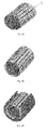
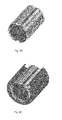
- Figs. 4A to 4E show a number of possible variations for shorting the damper bars. Other variations are also conceivable.
- Fig. 4A shows an embodiment in which all of the bars are shorted by providing continuous rings at two ends of the stator pack.
- Fig. 4B bars are shorted in groups of three.
- Fig. 4C shows how an embodiment such as shown in Fig. 4B is fitted into the stator pack.
- FIG. 4D Another embodiment is shown in Fig. 4D , in which bars are shorted in pairs and Fig. 4E shows how such an embodiment is built into the stator pack.
- the magnitude of damping can be controlled by selecting an appropriate shorting configuration, for example by shorting a given number of bars.
- the damping characteristic can be changed by changing the damper bar material.
- the present invention thus provides a passive damper arrangement integrated into an existing EMA electric motor, which has a robust and reliable construction.
- the present invention allows the damping function to be integrated into the motor components, as a single unit. Integration of the damper into the electric motor reduces both the volume and weight of the actuator and also enables the use of a single set of magnets for both motoring and damping. This will have a direct impact on the cost of the actuator. Furthermore, the reduction of component parts will increase its reliability.
Landscapes
- Engineering & Computer Science (AREA)
- Power Engineering (AREA)
- Iron Core Of Rotating Electric Machines (AREA)
Abstract
Description
- The present invention is concerned with a damping arrangement for an electromechanical actuator (EMA).
- Electromechanical actuators are used in a wide range of technology for actuating system parts, for example in engine, machine, vehicle or aviation technology.
- An EMA motor comprises a stator assembly and a rotor. Power is supplied to the stator which results in generation of forces causing the rotor to rotate relative to the stator.
- A stator assembly generally comprises a cylindrical back plate and a plurality of teeth extending radially inwards from the inner surface of the back plate. The teeth are separated by slots and electromagnetic coils are wound between the slots. The teeth surround a rotating central rotor having corresponding teeth. The resulting stator electromagnets are successfully energised by an external control circuit. As each electromagnet is powered, this creates an attractive force between the stator teeth and the rotor teeth to cause rotation of the rotor relative to the stator. A stator assembly generally consists of a set of magnetic steel laminations insulated from each other and glued, pressed or welded to form the stator core pack.
- Laminations are slotted, and wound with typically copper wire to form one or more pairs of magnetic poles when energised by an external supply.
- As the stator coils are energised they generate a magnetic field which will interact with the field produced by a set of magnets (in this case permanent magnets) placed on the motor rotor. The interaction between the two fields enables the motor to rotate.
- Electromechanical actuators are finding increased use in applications where previously hydraulic actuators have been used, e.g. in aircraft, such as in the primary and secondary flight control actuators and nose wheel steering systems, and also in many other fields, such as elevators, ships etc.
- Damping is often required in actuation systems or motor driven systems. For certain applications such as aileron, elevator or rudder for primary flight control or nose wheel steering damping function is required.
- This function is necessary to prevent flutter of aerodynamic surface for an aileron, elevator and rudder in case of a power loss scenario. It also prevents hitting roughly the mechanical stops in the situation of wind gust.
- For a nose wheel steering application damping will minimise nose wheel shimmy which is undesirable, and destructive.
- Where hydraulic systems are used, the damping function is provided by a bypass restrictor. Where an EMA is used, however, there is no hydraulic fluid and so an alternative damping mechanism is required. Existing EMA systems have used a damper unit or component bolted on to the electric motor, e.g. to the motor shaft. This, whilst effective, increases the overall weight and size of the motor and involves increased manufacture time and costs.
- The present invention aims to provide an improved electromechanical actuator motor damping arrangement.
- The invention provides a stator for an electric motor comprising a plurality of teeth separated by slots, and comprising conductive material provided in the slots between two or more of the teeth.
- By incorporating conductive material, e.g. in the form of bars, into the stator slots, a damping function can be achieved. The bars or the like can be located in the space usually occupied by stator slot wedges used to hold the stator windings in the slots formed between the stator teeth. The damping bars can then provide both a damping function, as well as a mechanical retainer for the windings.
- The conductive material is preferably nonmagnetic with a given resistivity such as copper, aluminium, bronze, etc. The material choice depends on the desired performance required from the damper.
- The conductive material may be in the form of rods or bars fitted into the stator slots just below the windings, although other configurations of conductive material could be provided in the slots.
- In order to obtain damping torque, he conductive material needs to be shorted.
- Where the conductive material is provided at or extends to the ends of the stator, the shorting can be done by, for example, providing a ring around the teeth in contact with the conductive material. The conductive material inserted into the stator slots need to be shorted to a cylindrical ring as it is a case in a conventional squirrel cage induction motor.
- The conductor bars, for example, embedded in the stator slots may be welded or electrically braced or even bolted at both ends to an end ring, thus maintaining electrical continuity
- Such shorting is, in preferred embodiments, provided at each axial end of the rotor.
- The magnitude of the damping torque can be tailored e.g. by selection of material resistivity or by shorting a defined number of bars rather than a complete ring.
- In operation of the motor, as the rotor magnets rotate, the magnetic flux will induce voltage into the conductive material. The relative motion between the stator and the rotor will generate a torque which will oppose the useful torque produced by the motor. Eddy-currents are created by the relative motion between the rotating permanent magnets on the rotor, and the stationary conductive bars integrated into the motor stator. The generated currents induce a drag torque, hence a deceleration of motion.
- The negative torque produced by the interaction of magnets and the cage on the stator needs to be overcome by the motor in case of positive torque demand.
- The characteristic of the drag torque is function of the rotor speed, the area of the conductive bars and the resistivity of the bars for a given magnetic field.
- Preferred embodiments of the invention will now be described, by way of example only, with reference to the drawings.
-
Fig. 1A is an end section view of the rotor and stator assembly of a conventional EMA motor. -
Fig. 1B is a partially cut-away perspective view of a conventional rotor and stator assembly. -
Fig. 2 is a sectional view through the motor according to an embodiment of the invention. -
Fig. 3 is a perspective view of one embodiment of the invention with the stator removed for clarity. -
Figs. 4A to 4E show some possible bar configurations. - Referring first to
Figs. 1A and 1B , an EMA generally comprises a motor having a rotor 1 and astator 2 assembly. - A stator assembly usually consists of a stator core pack or back plate 3 which is usually formed of a set of magnetic steel laminations insulated from each other and glued, pressed or welded together to form the stator pack. Laminations are slotted, to define a series of inwardly extending
teeth 4, and are wound with, typically, copper wire to form one or more pairs ofmagnetic poles 5 when energised by an external power supply. - As the
stator coils 5 are energised, they generate a magnetic field which will interact with the field produced by a set ofmagnets 6, e.g. permanent magnets, placed on the motor rotor. The interaction between the two fields causes relative movement of the rotor to the stator enabling the motor to rotate. - Other forms of motor are also known, for example where the stator pack is formed from compressed iron powder or the like.
- As can be seen, the form of the stator comprises
teeth 4 extending radially inwards from the stator back plate 3. - As seen in
Figs. 2 and 3 , in the present invention, damper bars or rods 7 are arranged in the stator slots between the teeth, preferably underneath the coils or windings. - To provide the damping effect, the damper bars are shorted.
- In one example, a
ring 8 is provided at each end of the stator pack, making contact with the respective ends of the damper bars to provide shorting. - Various forms of such a shorting ring or construction are possible. In some embodiments, all of the damper bars are shorted, but in other embodiments, only some bars need to be shorted.
- The ring can be a continuous simple ring (
Fig. 3 ) at the ends of the stator pack, making contact with all of the damper bars. -
Figs. 4A to 4E show a number of possible variations for shorting the damper bars. Other variations are also conceivable. -
Fig. 4A shows an embodiment in which all of the bars are shorted by providing continuous rings at two ends of the stator pack. - In the embodiment of
Fig. 4B , bars are shorted in groups of three.Fig. 4C shows how an embodiment such as shown inFig. 4B is fitted into the stator pack. - Another embodiment is shown in
Fig. 4D , in which bars are shorted in pairs andFig. 4E shows how such an embodiment is built into the stator pack. - The magnitude of damping can be controlled by selecting an appropriate shorting configuration, for example by shorting a given number of bars. Alternatively, or in addition, the damping characteristic can be changed by changing the damper bar material.
- The present invention thus provides a passive damper arrangement integrated into an existing EMA electric motor, which has a robust and reliable construction.
- The present invention allows the damping function to be integrated into the motor components, as a single unit. Integration of the damper into the electric motor reduces both the volume and weight of the actuator and also enables the use of a single set of magnets for both motoring and damping. This will have a direct impact on the cost of the actuator. Furthermore, the reduction of component parts will increase its reliability.
Claims (7)
- A stator for an electric motor comprising a plurality of teeth separated by slots, and comprising conductive material provided in the slots between two or more of the teeth.
- The stator of claim 1, wherein the conductive material is non-magnetic.
- The stator of claim 1 or 2, wherein the conductive material is in the form of bars extending in the slots from a first axial end of the stator to the second axial end.
- The stator of any preceding claim, further comprising means for shorting the conductive material.
- The stator of claim 4, wherein the means for shorting comprises a shorting ring in contact with the conductive material.
- The stator of claim 5, wherein the means for shorting comprises a shorting ring at each axial end of the stator.
- A motor comprising a rotor and a stator as claimed in any preceding claim.
Priority Applications (2)
| Application Number | Priority Date | Filing Date | Title |
|---|---|---|---|
| EP15164686.6A EP3086443B1 (en) | 2015-04-22 | 2015-04-22 | Electromechanical actuator damping |
| US15/135,854 US10263491B2 (en) | 2015-04-22 | 2016-04-22 | Electromechanical actuator damping |
Applications Claiming Priority (1)
| Application Number | Priority Date | Filing Date | Title |
|---|---|---|---|
| EP15164686.6A EP3086443B1 (en) | 2015-04-22 | 2015-04-22 | Electromechanical actuator damping |
Publications (2)
| Publication Number | Publication Date |
|---|---|
| EP3086443A1 true EP3086443A1 (en) | 2016-10-26 |
| EP3086443B1 EP3086443B1 (en) | 2022-02-23 |
Family
ID=52991648
Family Applications (1)
| Application Number | Title | Priority Date | Filing Date |
|---|---|---|---|
| EP15164686.6A Active EP3086443B1 (en) | 2015-04-22 | 2015-04-22 | Electromechanical actuator damping |
Country Status (2)
| Country | Link |
|---|---|
| US (1) | US10263491B2 (en) |
| EP (1) | EP3086443B1 (en) |
Families Citing this family (2)
| Publication number | Priority date | Publication date | Assignee | Title |
|---|---|---|---|---|
| EP3490113B1 (en) | 2017-11-24 | 2021-04-21 | Goodrich Actuation Systems Limited | Damped electric motor |
| CN110365135B (en) * | 2019-08-07 | 2024-08-27 | 安徽德科电气科技有限公司 | Permanent magnet machine stator magnetic circuit |
Citations (2)
| Publication number | Priority date | Publication date | Assignee | Title |
|---|---|---|---|---|
| DE401111C (en) * | 1924-08-30 | Bbc Brown Boveri & Cie | Device for suppressing harmonic voltages on synchronous alternating current generators | |
| US20080079401A1 (en) * | 2003-05-27 | 2008-04-03 | Dooley Kevin A | Architecture for electric machine |
Family Cites Families (2)
| Publication number | Priority date | Publication date | Assignee | Title |
|---|---|---|---|---|
| US20040070300A1 (en) * | 2002-10-10 | 2004-04-15 | Fu Zhenxing (Zack) | Low torque ripple surface mounted magnet synchronous motors for electric power assisted steering |
| EP2674256B1 (en) * | 2012-06-15 | 2021-11-10 | Black & Decker Inc. | Brushless motor commutation control in a power tool |
-
2015
- 2015-04-22 EP EP15164686.6A patent/EP3086443B1/en active Active
-
2016
- 2016-04-22 US US15/135,854 patent/US10263491B2/en active Active
Patent Citations (2)
| Publication number | Priority date | Publication date | Assignee | Title |
|---|---|---|---|---|
| DE401111C (en) * | 1924-08-30 | Bbc Brown Boveri & Cie | Device for suppressing harmonic voltages on synchronous alternating current generators | |
| US20080079401A1 (en) * | 2003-05-27 | 2008-04-03 | Dooley Kevin A | Architecture for electric machine |
Also Published As
| Publication number | Publication date |
|---|---|
| US10263491B2 (en) | 2019-04-16 |
| EP3086443B1 (en) | 2022-02-23 |
| US20160315519A1 (en) | 2016-10-27 |
Similar Documents
| Publication | Publication Date | Title |
|---|---|---|
| EP2630721B1 (en) | An improved magnetic motor | |
| US8446121B1 (en) | High performance actuator motor | |
| US10693402B2 (en) | Modified Halbach array generator | |
| EP2828960B1 (en) | Brushless dc motor | |
| US20090001831A1 (en) | Axial Field Electric Motor and Method | |
| US6217298B1 (en) | Electrodynamic transmission and a centrifugal pump with a transmission of this kind | |
| US20120153757A1 (en) | Polyphasic multi-coil electric device | |
| US2880335A (en) | Induction motor | |
| US20150015354A1 (en) | Halbach array electromagnet with substantially contiguous vertical and horizontal cores | |
| EP3163726A1 (en) | Flux control of permanent magnet electric machine | |
| JP2019097359A (en) | Rotary electric machine with magnetic flux variable mechanism | |
| WO2007057842A1 (en) | Linear variable reluctance actuator having band coils | |
| US10263491B2 (en) | Electromechanical actuator damping | |
| US10404121B2 (en) | Electromechanical actuator damping | |
| EP3156325A2 (en) | Saturation-controlled variable damper systems and methods | |
| US11804744B2 (en) | Axial flux electric machine including insulated hybrid stator core with soft magnetic composite portions and laminated layers | |
| US11239770B2 (en) | Motor with regenerative braking resistor | |
| EP3291414A2 (en) | Switched reluctance motor with axial laminated construction | |
| EP3714528B1 (en) | Apparatus and method for modular stabilization of hubless rotors | |
| KR102188617B1 (en) | Electric machine | |
| EP2763284A2 (en) | Construction arrangement of a permanent magnet rotor for a generator | |
| EP3084929B1 (en) | Stator for an electric machine | |
| CN105379071A (en) | Electric motor having a low short-circuit torque, drive device with a plurality of motors and method for producing such a motor | |
| CN208046333U (en) | Generator with stator and rotor | |
| JP2005520470A (en) | Motor / alternator / synchronous generator universal device |
Legal Events
| Date | Code | Title | Description |
|---|---|---|---|
| PUAI | Public reference made under article 153(3) epc to a published international application that has entered the european phase |
Free format text: ORIGINAL CODE: 0009012 |
|
| AK | Designated contracting states |
Kind code of ref document: A1 Designated state(s): AL AT BE BG CH CY CZ DE DK EE ES FI FR GB GR HR HU IE IS IT LI LT LU LV MC MK MT NL NO PL PT RO RS SE SI SK SM TR |
|
| AX | Request for extension of the european patent |
Extension state: BA ME |
|
| 17P | Request for examination filed |
Effective date: 20170426 |
|
| RBV | Designated contracting states (corrected) |
Designated state(s): AL AT BE BG CH CY CZ DE DK EE ES FI FR GB GR HR HU IE IS IT LI LT LU LV MC MK MT NL NO PL PT RO RS SE SI SK SM TR |
|
| STAA | Information on the status of an ep patent application or granted ep patent |
Free format text: STATUS: THE APPLICATION HAS BEEN PUBLISHED |
|
| STAA | Information on the status of an ep patent application or granted ep patent |
Free format text: STATUS: REQUEST FOR EXAMINATION WAS MADE |
|
| STAA | Information on the status of an ep patent application or granted ep patent |
Free format text: STATUS: EXAMINATION IS IN PROGRESS |
|
| 17Q | First examination report despatched |
Effective date: 20170921 |
|
| REG | Reference to a national code |
Ref country code: DE Ref legal event code: R079 Ref document number: 602015077037 Country of ref document: DE Free format text: PREVIOUS MAIN CLASS: H02K0003160000 Ipc: H02K0003200000 |
|
| GRAP | Despatch of communication of intention to grant a patent |
Free format text: ORIGINAL CODE: EPIDOSNIGR1 |
|
| STAA | Information on the status of an ep patent application or granted ep patent |
Free format text: STATUS: GRANT OF PATENT IS INTENDED |
|
| RIC1 | Information provided on ipc code assigned before grant |
Ipc: H02K 3/20 20060101AFI20210827BHEP |
|
| INTG | Intention to grant announced |
Effective date: 20210913 |
|
| GRAS | Grant fee paid |
Free format text: ORIGINAL CODE: EPIDOSNIGR3 |
|
| GRAA | (expected) grant |
Free format text: ORIGINAL CODE: 0009210 |
|
| STAA | Information on the status of an ep patent application or granted ep patent |
Free format text: STATUS: THE PATENT HAS BEEN GRANTED |
|
| AK | Designated contracting states |
Kind code of ref document: B1 Designated state(s): AL AT BE BG CH CY CZ DE DK EE ES FI FR GB GR HR HU IE IS IT LI LT LU LV MC MK MT NL NO PL PT RO RS SE SI SK SM TR |
|
| REG | Reference to a national code |
Ref country code: GB Ref legal event code: FG4D |
|
| REG | Reference to a national code |
Ref country code: CH Ref legal event code: EP |
|
| REG | Reference to a national code |
Ref country code: DE Ref legal event code: R096 Ref document number: 602015077037 Country of ref document: DE |
|
| REG | Reference to a national code |
Ref country code: AT Ref legal event code: REF Ref document number: 1471197 Country of ref document: AT Kind code of ref document: T Effective date: 20220315 |
|
| REG | Reference to a national code |
Ref country code: IE Ref legal event code: FG4D |
|
| REG | Reference to a national code |
Ref country code: LT Ref legal event code: MG9D |
|
| REG | Reference to a national code |
Ref country code: NL Ref legal event code: MP Effective date: 20220223 |
|
| REG | Reference to a national code |
Ref country code: AT Ref legal event code: MK05 Ref document number: 1471197 Country of ref document: AT Kind code of ref document: T Effective date: 20220223 |
|
| PG25 | Lapsed in a contracting state [announced via postgrant information from national office to epo] |
Ref country code: SE Free format text: LAPSE BECAUSE OF FAILURE TO SUBMIT A TRANSLATION OF THE DESCRIPTION OR TO PAY THE FEE WITHIN THE PRESCRIBED TIME-LIMIT Effective date: 20220223 Ref country code: RS Free format text: LAPSE BECAUSE OF FAILURE TO SUBMIT A TRANSLATION OF THE DESCRIPTION OR TO PAY THE FEE WITHIN THE PRESCRIBED TIME-LIMIT Effective date: 20220223 Ref country code: PT Free format text: LAPSE BECAUSE OF FAILURE TO SUBMIT A TRANSLATION OF THE DESCRIPTION OR TO PAY THE FEE WITHIN THE PRESCRIBED TIME-LIMIT Effective date: 20220623 Ref country code: NO Free format text: LAPSE BECAUSE OF FAILURE TO SUBMIT A TRANSLATION OF THE DESCRIPTION OR TO PAY THE FEE WITHIN THE PRESCRIBED TIME-LIMIT Effective date: 20220523 Ref country code: NL Free format text: LAPSE BECAUSE OF FAILURE TO SUBMIT A TRANSLATION OF THE DESCRIPTION OR TO PAY THE FEE WITHIN THE PRESCRIBED TIME-LIMIT Effective date: 20220223 Ref country code: LT Free format text: LAPSE BECAUSE OF FAILURE TO SUBMIT A TRANSLATION OF THE DESCRIPTION OR TO PAY THE FEE WITHIN THE PRESCRIBED TIME-LIMIT Effective date: 20220223 Ref country code: HR Free format text: LAPSE BECAUSE OF FAILURE TO SUBMIT A TRANSLATION OF THE DESCRIPTION OR TO PAY THE FEE WITHIN THE PRESCRIBED TIME-LIMIT Effective date: 20220223 Ref country code: ES Free format text: LAPSE BECAUSE OF FAILURE TO SUBMIT A TRANSLATION OF THE DESCRIPTION OR TO PAY THE FEE WITHIN THE PRESCRIBED TIME-LIMIT Effective date: 20220223 Ref country code: BG Free format text: LAPSE BECAUSE OF FAILURE TO SUBMIT A TRANSLATION OF THE DESCRIPTION OR TO PAY THE FEE WITHIN THE PRESCRIBED TIME-LIMIT Effective date: 20220523 |
|
| PG25 | Lapsed in a contracting state [announced via postgrant information from national office to epo] |
Ref country code: PL Free format text: LAPSE BECAUSE OF FAILURE TO SUBMIT A TRANSLATION OF THE DESCRIPTION OR TO PAY THE FEE WITHIN THE PRESCRIBED TIME-LIMIT Effective date: 20220223 Ref country code: LV Free format text: LAPSE BECAUSE OF FAILURE TO SUBMIT A TRANSLATION OF THE DESCRIPTION OR TO PAY THE FEE WITHIN THE PRESCRIBED TIME-LIMIT Effective date: 20220223 Ref country code: GR Free format text: LAPSE BECAUSE OF FAILURE TO SUBMIT A TRANSLATION OF THE DESCRIPTION OR TO PAY THE FEE WITHIN THE PRESCRIBED TIME-LIMIT Effective date: 20220524 Ref country code: FI Free format text: LAPSE BECAUSE OF FAILURE TO SUBMIT A TRANSLATION OF THE DESCRIPTION OR TO PAY THE FEE WITHIN THE PRESCRIBED TIME-LIMIT Effective date: 20220223 Ref country code: AT Free format text: LAPSE BECAUSE OF FAILURE TO SUBMIT A TRANSLATION OF THE DESCRIPTION OR TO PAY THE FEE WITHIN THE PRESCRIBED TIME-LIMIT Effective date: 20220223 |
|
| PG25 | Lapsed in a contracting state [announced via postgrant information from national office to epo] |
Ref country code: IS Free format text: LAPSE BECAUSE OF FAILURE TO SUBMIT A TRANSLATION OF THE DESCRIPTION OR TO PAY THE FEE WITHIN THE PRESCRIBED TIME-LIMIT Effective date: 20220623 |
|
| PG25 | Lapsed in a contracting state [announced via postgrant information from national office to epo] |
Ref country code: SM Free format text: LAPSE BECAUSE OF FAILURE TO SUBMIT A TRANSLATION OF THE DESCRIPTION OR TO PAY THE FEE WITHIN THE PRESCRIBED TIME-LIMIT Effective date: 20220223 Ref country code: SK Free format text: LAPSE BECAUSE OF FAILURE TO SUBMIT A TRANSLATION OF THE DESCRIPTION OR TO PAY THE FEE WITHIN THE PRESCRIBED TIME-LIMIT Effective date: 20220223 Ref country code: RO Free format text: LAPSE BECAUSE OF FAILURE TO SUBMIT A TRANSLATION OF THE DESCRIPTION OR TO PAY THE FEE WITHIN THE PRESCRIBED TIME-LIMIT Effective date: 20220223 Ref country code: EE Free format text: LAPSE BECAUSE OF FAILURE TO SUBMIT A TRANSLATION OF THE DESCRIPTION OR TO PAY THE FEE WITHIN THE PRESCRIBED TIME-LIMIT Effective date: 20220223 Ref country code: DK Free format text: LAPSE BECAUSE OF FAILURE TO SUBMIT A TRANSLATION OF THE DESCRIPTION OR TO PAY THE FEE WITHIN THE PRESCRIBED TIME-LIMIT Effective date: 20220223 Ref country code: CZ Free format text: LAPSE BECAUSE OF FAILURE TO SUBMIT A TRANSLATION OF THE DESCRIPTION OR TO PAY THE FEE WITHIN THE PRESCRIBED TIME-LIMIT Effective date: 20220223 |
|
| REG | Reference to a national code |
Ref country code: DE Ref legal event code: R097 Ref document number: 602015077037 Country of ref document: DE |
|
| PG25 | Lapsed in a contracting state [announced via postgrant information from national office to epo] |
Ref country code: AL Free format text: LAPSE BECAUSE OF FAILURE TO SUBMIT A TRANSLATION OF THE DESCRIPTION OR TO PAY THE FEE WITHIN THE PRESCRIBED TIME-LIMIT Effective date: 20220223 |
|
| REG | Reference to a national code |
Ref country code: CH Ref legal event code: PL |
|
| PLBE | No opposition filed within time limit |
Free format text: ORIGINAL CODE: 0009261 |
|
| STAA | Information on the status of an ep patent application or granted ep patent |
Free format text: STATUS: NO OPPOSITION FILED WITHIN TIME LIMIT |
|
| REG | Reference to a national code |
Ref country code: BE Ref legal event code: MM Effective date: 20220430 |
|
| PG25 | Lapsed in a contracting state [announced via postgrant information from national office to epo] |
Ref country code: MC Free format text: LAPSE BECAUSE OF FAILURE TO SUBMIT A TRANSLATION OF THE DESCRIPTION OR TO PAY THE FEE WITHIN THE PRESCRIBED TIME-LIMIT Effective date: 20220223 Ref country code: LU Free format text: LAPSE BECAUSE OF NON-PAYMENT OF DUE FEES Effective date: 20220422 Ref country code: LI Free format text: LAPSE BECAUSE OF NON-PAYMENT OF DUE FEES Effective date: 20220430 Ref country code: CH Free format text: LAPSE BECAUSE OF NON-PAYMENT OF DUE FEES Effective date: 20220430 |
|
| 26N | No opposition filed |
Effective date: 20221124 |
|
| PG25 | Lapsed in a contracting state [announced via postgrant information from national office to epo] |
Ref country code: SI Free format text: LAPSE BECAUSE OF FAILURE TO SUBMIT A TRANSLATION OF THE DESCRIPTION OR TO PAY THE FEE WITHIN THE PRESCRIBED TIME-LIMIT Effective date: 20220223 Ref country code: BE Free format text: LAPSE BECAUSE OF NON-PAYMENT OF DUE FEES Effective date: 20220430 |
|
| PG25 | Lapsed in a contracting state [announced via postgrant information from national office to epo] |
Ref country code: IE Free format text: LAPSE BECAUSE OF NON-PAYMENT OF DUE FEES Effective date: 20220422 |
|
| P01 | Opt-out of the competence of the unified patent court (upc) registered |
Effective date: 20230706 |
|
| PG25 | Lapsed in a contracting state [announced via postgrant information from national office to epo] |
Ref country code: HU Free format text: LAPSE BECAUSE OF FAILURE TO SUBMIT A TRANSLATION OF THE DESCRIPTION OR TO PAY THE FEE WITHIN THE PRESCRIBED TIME-LIMIT; INVALID AB INITIO Effective date: 20150422 |
|
| PG25 | Lapsed in a contracting state [announced via postgrant information from national office to epo] |
Ref country code: MK Free format text: LAPSE BECAUSE OF FAILURE TO SUBMIT A TRANSLATION OF THE DESCRIPTION OR TO PAY THE FEE WITHIN THE PRESCRIBED TIME-LIMIT Effective date: 20220223 Ref country code: CY Free format text: LAPSE BECAUSE OF FAILURE TO SUBMIT A TRANSLATION OF THE DESCRIPTION OR TO PAY THE FEE WITHIN THE PRESCRIBED TIME-LIMIT Effective date: 20220223 |
|
| PG25 | Lapsed in a contracting state [announced via postgrant information from national office to epo] |
Ref country code: TR Free format text: LAPSE BECAUSE OF FAILURE TO SUBMIT A TRANSLATION OF THE DESCRIPTION OR TO PAY THE FEE WITHIN THE PRESCRIBED TIME-LIMIT Effective date: 20220223 |
|
| PG25 | Lapsed in a contracting state [announced via postgrant information from national office to epo] |
Ref country code: MT Free format text: LAPSE BECAUSE OF FAILURE TO SUBMIT A TRANSLATION OF THE DESCRIPTION OR TO PAY THE FEE WITHIN THE PRESCRIBED TIME-LIMIT Effective date: 20220223 |
|
| PGFP | Annual fee paid to national office [announced via postgrant information from national office to epo] |
Ref country code: FR Payment date: 20250319 Year of fee payment: 11 |
|
| PGFP | Annual fee paid to national office [announced via postgrant information from national office to epo] |
Ref country code: IT Payment date: 20250319 Year of fee payment: 11 |
|
| PGFP | Annual fee paid to national office [announced via postgrant information from national office to epo] |
Ref country code: DE Payment date: 20250319 Year of fee payment: 11 |
|
| PGFP | Annual fee paid to national office [announced via postgrant information from national office to epo] |
Ref country code: GB Payment date: 20260327 Year of fee payment: 12 |