EP2828960B1 - Brushless dc motor - Google Patents
Brushless dc motor Download PDFInfo
- Publication number
- EP2828960B1 EP2828960B1 EP13764925.7A EP13764925A EP2828960B1 EP 2828960 B1 EP2828960 B1 EP 2828960B1 EP 13764925 A EP13764925 A EP 13764925A EP 2828960 B1 EP2828960 B1 EP 2828960B1
- Authority
- EP
- European Patent Office
- Prior art keywords
- rotor
- solenoids
- brushless
- magnets
- motor according
- Prior art date
- Legal status (The legal status is an assumption and is not a legal conclusion. Google has not performed a legal analysis and makes no representation as to the accuracy of the status listed.)
- Active
Links
Images


Classifications
-
- H—ELECTRICITY
- H02—GENERATION; CONVERSION OR DISTRIBUTION OF ELECTRIC POWER
- H02K—DYNAMO-ELECTRIC MACHINES
- H02K11/00—Structural association of dynamo-electric machines with electric components or with devices for shielding, monitoring or protection
- H02K11/0094—Structural association with other electrical or electronic devices
-
- H—ELECTRICITY
- H02—GENERATION; CONVERSION OR DISTRIBUTION OF ELECTRIC POWER
- H02K—DYNAMO-ELECTRIC MACHINES
- H02K29/00—Motors or generators having non-mechanical commutating devices, e.g. discharge tubes or semiconductor devices
- H02K29/06—Motors or generators having non-mechanical commutating devices, e.g. discharge tubes or semiconductor devices with position sensing devices
- H02K29/08—Motors or generators having non-mechanical commutating devices, e.g. discharge tubes or semiconductor devices with position sensing devices using magnetic effect devices, e.g. Hall-plates, magneto-resistors
-
- H—ELECTRICITY
- H02—GENERATION; CONVERSION OR DISTRIBUTION OF ELECTRIC POWER
- H02K—DYNAMO-ELECTRIC MACHINES
- H02K21/00—Synchronous motors having permanent magnets; Synchronous generators having permanent magnets
- H02K21/12—Synchronous motors having permanent magnets; Synchronous generators having permanent magnets with stationary armatures and rotating magnets
-
- H—ELECTRICITY
- H02—GENERATION; CONVERSION OR DISTRIBUTION OF ELECTRIC POWER
- H02K—DYNAMO-ELECTRIC MACHINES
- H02K49/00—Dynamo-electric clutches; Dynamo-electric brakes
- H02K49/10—Dynamo-electric clutches; Dynamo-electric brakes of the permanent-magnet type
- H02K49/104—Magnetic couplings consisting of only two coaxial rotary elements, i.e. the driving element and the driven element
- H02K49/106—Magnetic couplings consisting of only two coaxial rotary elements, i.e. the driving element and the driven element with a radial air gap
-
- F—MECHANICAL ENGINEERING; LIGHTING; HEATING; WEAPONS; BLASTING
- F16—ENGINEERING ELEMENTS AND UNITS; GENERAL MEASURES FOR PRODUCING AND MAINTAINING EFFECTIVE FUNCTIONING OF MACHINES OR INSTALLATIONS; THERMAL INSULATION IN GENERAL
- F16D—COUPLINGS FOR TRANSMITTING ROTATION; CLUTCHES; BRAKES
- F16D27/00—Magnetically- or electrically- actuated clutches; Control or electric circuits therefor
-
- H—ELECTRICITY
- H02—GENERATION; CONVERSION OR DISTRIBUTION OF ELECTRIC POWER
- H02K—DYNAMO-ELECTRIC MACHINES
- H02K1/00—Details of the magnetic circuit
- H02K1/06—Details of the magnetic circuit characterised by the shape, form or construction
- H02K1/22—Rotating parts of the magnetic circuit
- H02K1/27—Rotor cores with permanent magnets
- H02K1/2706—Inner rotors
- H02K1/272—Inner rotors the magnetisation axis of the magnets being perpendicular to the rotor axis
- H02K1/2726—Inner rotors the magnetisation axis of the magnets being perpendicular to the rotor axis the rotor consisting of a single magnet or two or more axially juxtaposed single magnets
-
- H—ELECTRICITY
- H02—GENERATION; CONVERSION OR DISTRIBUTION OF ELECTRIC POWER
- H02K—DYNAMO-ELECTRIC MACHINES
- H02K1/00—Details of the magnetic circuit
- H02K1/06—Details of the magnetic circuit characterised by the shape, form or construction
- H02K1/22—Rotating parts of the magnetic circuit
- H02K1/27—Rotor cores with permanent magnets
- H02K1/2706—Inner rotors
- H02K1/272—Inner rotors the magnetisation axis of the magnets being perpendicular to the rotor axis
- H02K1/274—Inner rotors the magnetisation axis of the magnets being perpendicular to the rotor axis the rotor consisting of two or more circumferentially positioned magnets
- H02K1/2753—Inner rotors the magnetisation axis of the magnets being perpendicular to the rotor axis the rotor consisting of two or more circumferentially positioned magnets the rotor consisting of magnets or groups of magnets arranged with alternating polarity
-
- H—ELECTRICITY
- H02—GENERATION; CONVERSION OR DISTRIBUTION OF ELECTRIC POWER
- H02K—DYNAMO-ELECTRIC MACHINES
- H02K21/00—Synchronous motors having permanent magnets; Synchronous generators having permanent magnets
- H02K21/12—Synchronous motors having permanent magnets; Synchronous generators having permanent magnets with stationary armatures and rotating magnets
- H02K21/22—Synchronous motors having permanent magnets; Synchronous generators having permanent magnets with stationary armatures and rotating magnets with magnets rotating around the armatures, e.g. flywheel magnetos
-
- H—ELECTRICITY
- H02—GENERATION; CONVERSION OR DISTRIBUTION OF ELECTRIC POWER
- H02K—DYNAMO-ELECTRIC MACHINES
- H02K29/00—Motors or generators having non-mechanical commutating devices, e.g. discharge tubes or semiconductor devices
-
- H—ELECTRICITY
- H02—GENERATION; CONVERSION OR DISTRIBUTION OF ELECTRIC POWER
- H02K—DYNAMO-ELECTRIC MACHINES
- H02K29/00—Motors or generators having non-mechanical commutating devices, e.g. discharge tubes or semiconductor devices
- H02K29/06—Motors or generators having non-mechanical commutating devices, e.g. discharge tubes or semiconductor devices with position sensing devices
- H02K29/10—Motors or generators having non-mechanical commutating devices, e.g. discharge tubes or semiconductor devices with position sensing devices using light effect devices
-
- H—ELECTRICITY
- H02—GENERATION; CONVERSION OR DISTRIBUTION OF ELECTRIC POWER
- H02K—DYNAMO-ELECTRIC MACHINES
- H02K41/00—Propulsion systems in which a rigid body is moved along a path due to dynamo-electric interaction between the body and a magnetic field travelling along the path
- H02K41/02—Linear motors; Sectional motors
- H02K41/035—DC motors; Unipolar motors
- H02K41/0352—Unipolar motors
- H02K41/0354—Lorentz force motors, e.g. voice coil motors
- H02K41/0358—Lorentz force motors, e.g. voice coil motors moving along a curvilinear path
-
- H—ELECTRICITY
- H02—GENERATION; CONVERSION OR DISTRIBUTION OF ELECTRIC POWER
- H02K—DYNAMO-ELECTRIC MACHINES
- H02K7/00—Arrangements for handling mechanical energy structurally associated with dynamo-electric machines, e.g. structural association with mechanical driving motors or auxiliary dynamo-electric machines
- H02K7/08—Structural association with bearings
- H02K7/083—Structural association with bearings radially supporting the rotary shaft at both ends of the rotor
-
- H—ELECTRICITY
- H02—GENERATION; CONVERSION OR DISTRIBUTION OF ELECTRIC POWER
- H02K—DYNAMO-ELECTRIC MACHINES
- H02K7/00—Arrangements for handling mechanical energy structurally associated with dynamo-electric machines, e.g. structural association with mechanical driving motors or auxiliary dynamo-electric machines
- H02K7/10—Structural association with clutches, brakes, gears, pulleys or mechanical starters
- H02K7/11—Structural association with clutches, brakes, gears, pulleys or mechanical starters with dynamo-electric clutches
-
- H—ELECTRICITY
- H02—GENERATION; CONVERSION OR DISTRIBUTION OF ELECTRIC POWER
- H02K—DYNAMO-ELECTRIC MACHINES
- H02K7/00—Arrangements for handling mechanical energy structurally associated with dynamo-electric machines, e.g. structural association with mechanical driving motors or auxiliary dynamo-electric machines
- H02K7/10—Structural association with clutches, brakes, gears, pulleys or mechanical starters
- H02K7/116—Structural association with clutches, brakes, gears, pulleys or mechanical starters with gears
-
- H—ELECTRICITY
- H02—GENERATION; CONVERSION OR DISTRIBUTION OF ELECTRIC POWER
- H02P—CONTROL OR REGULATION OF ELECTRIC MOTORS, ELECTRIC GENERATORS OR DYNAMO-ELECTRIC CONVERTERS; CONTROLLING TRANSFORMERS, REACTORS OR CHOKE COILS
- H02P6/00—Arrangements for controlling synchronous motors or other dynamo-electric motors using electronic commutation dependent on the rotor position; Electronic commutators therefor
- H02P6/14—Electronic commutators
-
- H—ELECTRICITY
- H02—GENERATION; CONVERSION OR DISTRIBUTION OF ELECTRIC POWER
- H02K—DYNAMO-ELECTRIC MACHINES
- H02K11/00—Structural association of dynamo-electric machines with electric components or with devices for shielding, monitoring or protection
- H02K11/20—Structural association of dynamo-electric machines with electric components or with devices for shielding, monitoring or protection for measuring, monitoring, testing, protecting or switching
- H02K11/21—Devices for sensing speed or position, or actuated thereby
- H02K11/215—Magnetic effect devices, e.g. Hall-effect or magneto-resistive elements
-
- H—ELECTRICITY
- H02—GENERATION; CONVERSION OR DISTRIBUTION OF ELECTRIC POWER
- H02K—DYNAMO-ELECTRIC MACHINES
- H02K11/00—Structural association of dynamo-electric machines with electric components or with devices for shielding, monitoring or protection
- H02K11/20—Structural association of dynamo-electric machines with electric components or with devices for shielding, monitoring or protection for measuring, monitoring, testing, protecting or switching
- H02K11/21—Devices for sensing speed or position, or actuated thereby
- H02K11/22—Optical devices
-
- H—ELECTRICITY
- H02—GENERATION; CONVERSION OR DISTRIBUTION OF ELECTRIC POWER
- H02K—DYNAMO-ELECTRIC MACHINES
- H02K11/00—Structural association of dynamo-electric machines with electric components or with devices for shielding, monitoring or protection
- H02K11/30—Structural association with control circuits or drive circuits
- H02K11/33—Drive circuits, e.g. power electronics
-
- H—ELECTRICITY
- H02—GENERATION; CONVERSION OR DISTRIBUTION OF ELECTRIC POWER
- H02K—DYNAMO-ELECTRIC MACHINES
- H02K5/00—Casings; Enclosures; Supports
- H02K5/04—Casings or enclosures characterised by the shape, form or construction thereof
- H02K5/16—Means for supporting bearings, e.g. insulating supports or means for fitting bearings in the bearing-shields
- H02K5/167—Means for supporting bearings, e.g. insulating supports or means for fitting bearings in the bearing-shields using sliding-contact or spherical cap bearings
- H02K5/1672—Means for supporting bearings, e.g. insulating supports or means for fitting bearings in the bearing-shields using sliding-contact or spherical cap bearings radially supporting the rotary shaft at both ends of the rotor
Definitions
- the invention relates to Brushless DC Motors (BLDC).
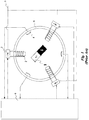
- a BLDC motor In its simplest conceptual form (shown in Fig. 1 ), a BLDC motor consists of a permanent magnet 1 (the rotor) which is free to rotate around its axis of symmetry, surrounded by an arrangement of at least three fixed electromagnets (the stator) consisting of solenoid windings 2, positioned at 120° relative to each other around the rotor axis. Each solenoid is energized by applying to it a DC (Direct Current) voltage, by means of a set of electronic switches 3, operated with timing and polarity determined by a switch-control algorithm.
- DC Direct Current
- the electromagnets are energized with the proper timing and polarity, they generate a magnetic field with the proper strength and direction relative to the S-N axis direction of rotor magnet 1, and this magnetic field produces a torque on the permanent magnet causing the rotor to turn.
- the algorithm determines the required operating sequence of the switches at any given moment, according to the actual angular position of the rotor, said position being determined by means of one or more sensors, usually of the Hall type (indicated in the figure by numeral 4), which sense the magnetic field of the rotor.
- the operation of the motor which is housed in a housing 5, is controlled by a controller 6.
- BLDC motors are implemented using many windings for the stator, and several magnets with alternating N-S poles for the rotor.
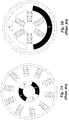
- BLDC motors There are two basic BLDC motor architectures known in the art: the inner rotor architecture ( Fig. 2a ), where the stator windings surround the rotor and are affixed to the motor's housing, and the outer rotor architecture ( Fig. 2b ), where the stator solenoids are affixed in the core of the motor, and are surrounded by the rotor magnets.
- BLDC motors suffer from the following drawback: for a fixed supply voltage, as the motor speed increases there is a decrease in the torque that the motor can provide. This undesirable effect is the result of the generation of a parasitic voltage, known as the back EMF (Electromotive Force) voltage.
- the back EMF Electrotive Force
- the back EMF is a voltage generated in the stator much in the same way an electric generator works, because there is relative motion between the solenoids of the stator and the magnetic field created by the permanent magnets of the rotor.
- the magnetic field lines created by the permanent magnets rotate along with the rotor.
- the projection (in the direction of the solenoid axis) of the magnetic field lines entering the cross-sectional area of each of the energized solenoids changes with time.
- This projection of field lines adds up to a quantity referred to as "the magnetic flux" through the solenoid.
- this induced voltage increases proportionally to the rate by which the flux changes, and therefore it increases with increasing rotating speed of the motor, and its polarity opposes the original voltage externally applied by the supply.
- the overall effective voltage applied to each energized solenoid of the stator decreases with increasing angular velocity of the rotor (the overall voltage equals the constant external supply voltage, reduced by the induced back EMF. Due to the decrease in the overall voltage applied, the current flowing into the solenoids of the stator decreases too, which ultimately results in a reduction of the torque provided by the motor. Therefore, the maximal torque that the motor can deliver drops as the rotating speed increases. In order to increase back to torque at high speed, one needs to increase the supply voltage, an operation which in many instances cannot be done.
- US 6,252,317 discloses a DC brushless motor that comprises an annular rotor provided with permanent magnets which pass through stator coils when the rotor rotates. The position of the rotor is detected and corresponding electrical energy is applied to the coils to induce electromagnetic fields which couple with the magnetic fields of the permanent magnets. When the electrical energy is alternated between a certain voltage level and polarity, each coil is able to simultaneously attract and repel two adjacent magnets, to cause rotational movement of the rotor.
- the invention relates a brushless DC motor, comprising a plurality of magnets positioned at a distance from one another on a circular structure, and a plurality of solenoids provided each around a static solenoid housing, wherein each of said solenoid housings is structured with a void portion through which said plurality of magnets can pass when the circular structure comprising said plurality of magnets rotates around its axis.
- the motion of the magnets with respect to the solenoids is quasi-linear in the direction of the axis of the solenoid.
- the term "quasi-linear" is mean to indicate that when the magnet enters the housing of the solenoid, its movement is almost linear with respect to the axis of the solenoid.
- the spacers provided between adjacent permanent magnets are made of high permeability material.
- the number of solenoids equals the number of permanent magnets and according to another embodiment of the invention the number of solenoids can be greater or smaller than the number of permanent magnets.
- the brushless motor of the invention should be provided with one or more sensors suitable to determine the position of permanent magnets relative to solenoids.
- a controller should further be provided, suitable to allow the supply of current to solenoid in response to a determination by one or more sensors regarding the position of magnets relative to solenoids.
- the permanent magnets and the high-permeability material located between them alone or together with one or more structuring ring, form of the rotor of the motor, which is mechanically connected to power-transmitting means, e.g., by a toothed element.
- the invention in another aspect relates to a method for operating a brushless DC motor, comprising causing a plurality of magnets to move with respect to a plurality of solenoids in a quasi-linear motion in the direction of the axis of the solenoid.
- the invention is concerned with a novel type of BLDC motor architecture, which leads to a major reduction of back EMF levels, thus yielding a motor capable of providing a constant torque value regardless of the angular velocity of the rotor.
- the overall applied voltage is nearly constant, and therefore no over-current peaks at start will occur.
- the cause of back EMF generation in prior-art BLDC is the change in magnetic flux through the solenoids of the stator.
- This flux change is due to the spinning of the rotor, which produces both changes in the magnetic field strength present within the core of the solenoid (as a magnet of the rotor approaches a solenoid or moves away from it), as well as changes in the direction of the field lines with respect to the axis of the solenoids (a change in the component of the magnetic field crossing the core of the solenoid parallel to its axis produces a change in magnetic flux through it).
- the architecture subject of the invention reduces the back EMF effect by reducing the above-mentioned flux changes.
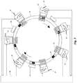
- the motor architecture according to an example is schematically shown in Fig. 3 , for the purpose of explaining the principle by which it operates.
- the stator architecture consists of a number of air-core solenoids 32 affixed to the motor housing, and whose axis of symmetry is aligned along a circular path 35.
- the basic rotor architecture consists of a number of permanent magnets 31 whose S-N axis is aligned with alternate polarity along the same circular path as the stator. The magnets are connected to each other with a high-permeability material therebetween to form a continuous circular ring as shown in Fig. 5 .
- the magnets may be mounted onto a circular flat base 35 and the space between them may be left open to air as in Fig. 3 .
- the number of magnets may be larger, equal, or smaller than the number of the solenoids.
- the rotor is supported by rotating mechanical bearings (not shown) and is free to rotate around the center of its circular shape while passing inside the core of the solenoids of the stator as shown in Fig. 6 .
- the solenoids are electrically connected to the DC supply through a system of switches 33, preferably, but not limitatively, of the electronic type, which determines, at each instant, the polarity and the level of the voltage applied to each solenoid in the stator.
- the switches are controlled by an apparatus, preferably a microcontroller 36 with associated software, which determines at each instant the DC polarity applied to each solenoid (e.g., by inverting the DC connection to it), as well as the average DC level (e.g., by applying the DC supply voltage using Pulse Width Modulation (PWM)).
- PWM Pulse Width Modulation
- the angular position of the rotor at each instant is detected by a system of sensors 34 (e.g., optical sensors or Hall-effect sensors).
- the sensor output is fed to the controller, which operates the switches according to the status of the rotor (i.e. angular position, speed and acceleration).
- the nearby magnets of the rotor move along the circular path of the stator.
- the magnet is either pulled-in towards the solenoid core, or pushed-out from it, depending on the polarity of the switch associated with said solenoid, which determines the direction of flow of the current in the windings, and on the orientation of the magnets (N-N or S-S).
- the status of said switch is determined at each time by the controller, based on the angular position of the rotor detected by the sensors. Under the proper simultaneous operating sequence of the overall system of switches, it is possible to obtain a continuous smooth rotation of the rotor in either spinning direction.
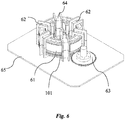
- the motion of the rotor is then transferred to the load by means of a mechanical gear 63 coupled to the rotor ring, as shown in Fig. 6 .
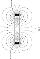
- the transversal magnetic field is additive, while the axial magnetic field is subtractive.
- the (axial) magnetic field directed along the ring of the rotor in the region between the S-S or N-N poles of the magnets (and therefore in a direction along the solenoid axis) exhibits small variations between two magnets. While the transversal magnetic field contributes to the mechanical attraction/repulsion between the magnets and the solenoid (due to Lorentz's force law) it does not contribute to the magnetic flux through the solenoid.
- the (axial) magnetic field component directed along the axis of the solenoid, is the one that contributes to the magnetic flux through the solenoid.
- the magnets of the rotor move in a direction collinear to the solenoid axis, and the field component in the collinear (axial) direction exhibits small variations in the region 43 between two repulsing magnets. It follows that there will be a small change in magnetic flux during the transition, through the solenoid core, of any rotor section located between any two magnets, and therefore the back EMF generated during said transition will be small.
- the solenoids are energized with the proper timing sequence, the back EMF effect opposing the DC supply voltage can be made small.
- Fig. 5 schematically shows a rotor architecture that is suitable for a circular, rotating brushless DC motor according to one embodiment of the invention.
- the rotor consists of a plurality of permanent magnets 51 (in the example of the figure, 5 of them are shown) separated by a high permeability material 52, as may be, for instance, iron.
- a high permeability material 52 as may be, for instance, iron.
- every two magnets 51 are separated by a segment 52 made of highly permeable material, and all the magnets and separating segments together form a ring-like structure.
- it may be convenient to position the magnets at identical distances between them it may also be possible to employ an asymmetric distribution of the magnets on the circumference on which they are disposed.
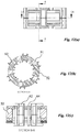
- Fig. 6 a general, schematic view of the motor according to this particular embodiment of the invention is seen in its assembled, operating condition. Details of the various constructive elements of the motor shown in this figure will be further illustrated with reference to Figs. 7-14 .
- the rotor 61 rotates inside a plurality of solenoid assemblies 62. Power generated by the motor is transferred out, according to this particular embodiment, using a gear 63. The moment of the rotor is supported by bearings 64, which may be of any suitable type.
- the assembly is positioned on a base 65.
- toothed ring 101 also shown in the figure is toothed ring 101, which will be further discussed with reference to Fig. 10 .
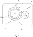
- Fig. 7 is a top view of the motor of Fig. 6 , showing the same elements
- Fig. 8 is a side view of the same motor.
- Fig. 9 shows the upper ring 91, which is positioned above rotor 61, and illustrates its structural relationship with bearings 64.
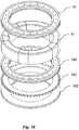
- the ring assembly associated with rotor 61 is shown in Fig. 10 .
- a number of rings are associated with rotor 61.
- Upper ring 91 already described with reference to Fig. 9 , is positioned atop the rotor 61, and a rotor bottom ring 100 is positioned below the rotor which rests on it.
- toothed ring 101 is in geared cooperation with gear 63 of Fig. 6 .
- a bottom ring 102 is used to separate between base 65 of Fig. 6 and toothed ring 101.
- the assembly of the rings shown in Fig. 10 is connected together so that all rings rotate together and power is transferred to gear 63.
- Fig. 6 The motor of Fig. 6 is shown in exploded view in Fig. 11 , using the same reference numbers as in the previous figures.
- the solenoid housing 62 is conveniently made of two pieces, to make the assembly possible.
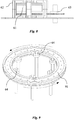
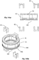
- Fig. 12 further illustrates the motor of Fig. 6 , with its central part being shown in Fig. 12(a) .
- Two cross-sections are further shown in the figure, with Section A-A being an horizontal cross-section ( Fig. 12 (b) ), and Section B-B being a vertical cross-section.
- Fig. 13 illustrates the positioning of the permanent magnets 51 on ring 100.
- Fig. 13(b) is a cross-section of ring 100 of Fig. 13(a) , taken along the D-D plane, showing a magnet 51 in place.
- lower protrusion 131 of permanent magnets 51 fits its female counterpart, i.e.
- Fig. 13(c) shows magnet 51 during its placement into the groove of ring 100
- Fig. 13(d) is a perspective view of one such magnet already in place, as in Fig. 13(b) .
- the additional magnets, as well as the separating high permeability material (52 of Fig. 5 ) are similarly located, and when all elements have been placed and rings 91 and 100 are put in place, the rotor assembly is ready to be positioned above toothed ring 101.
- Fig. 14 The various elements and their assembly is further illustrated in Fig. 14 , where the various parts are identified by the same numerals as in the previous figures. Looking now at Figs. 3 and 6 , to be understood that solenoid housings 62 will be provided with a coil around them, which in turn will be connected to a DC supply.
- FIG. 15 an alternative rotor architecture is illustrated, comprising a plurality of structures consisting of a magnet 151 which is fixed on a base (not shown), and is flanked by a high-permeability material 152, such as iron, on both sides. Gaps, indicated by arrow 153, are left between each such two structures.
Description
- The invention relates to Brushless DC Motors (BLDC).
- In its simplest conceptual form (shown in
Fig. 1 ), a BLDC motor consists of a permanent magnet 1 (the rotor) which is free to rotate around its axis of symmetry, surrounded by an arrangement of at least three fixed electromagnets (the stator) consisting of solenoid windings 2, positioned at 120° relative to each other around the rotor axis. Each solenoid is energized by applying to it a DC (Direct Current) voltage, by means of a set of electronic switches 3, operated with timing and polarity determined by a switch-control algorithm. - If the electromagnets are energized with the proper timing and polarity, they generate a magnetic field with the proper strength and direction relative to the S-N axis direction of rotor magnet 1, and this magnetic field produces a torque on the permanent magnet causing the rotor to turn. The algorithm determines the required operating sequence of the switches at any given moment, according to the actual angular position of the rotor, said position being determined by means of one or more sensors, usually of the Hall type (indicated in the figure by numeral 4), which sense the magnetic field of the rotor. The operation of the motor, which is housed in a housing 5, is controlled by a
controller 6. - In the simple conceptual form of
Fig. 1 , it is enough to properly energize two magnets at a time in order to generate a rotating magnetic field of arbitrary direction that will keep the rotor turning. In practice, in order to obtain a continuous smooth torque value, BLDC motors are implemented using many windings for the stator, and several magnets with alternating N-S poles for the rotor. - There are two basic BLDC motor architectures known in the art: the inner rotor architecture (
Fig. 2a ), where the stator windings surround the rotor and are affixed to the motor's housing, and the outer rotor architecture (Fig. 2b ), where the stator solenoids are affixed in the core of the motor, and are surrounded by the rotor magnets. In the prior art implementations, BLDC motors suffer from the following drawback: for a fixed supply voltage, as the motor speed increases there is a decrease in the torque that the motor can provide. This undesirable effect is the result of the generation of a parasitic voltage, known as the back EMF (Electromotive Force) voltage. - The back EMF is a voltage generated in the stator much in the same way an electric generator works, because there is relative motion between the solenoids of the stator and the magnetic field created by the permanent magnets of the rotor. The magnetic field lines created by the permanent magnets rotate along with the rotor. Thus, the projection (in the direction of the solenoid axis) of the magnetic field lines entering the cross-sectional area of each of the energized solenoids, changes with time. This projection of field lines adds up to a quantity referred to as "the magnetic flux" through the solenoid. By Lenz's law of induction, a changing magnetic flux produces an induced voltage in the solenoids (in this respect, the motor acts like a generator). The value of this induced voltage increases proportionally to the rate by which the flux changes, and therefore it increases with increasing rotating speed of the motor, and its polarity opposes the original voltage externally applied by the supply. As a result, the overall effective voltage applied to each energized solenoid of the stator decreases with increasing angular velocity of the rotor (the overall voltage equals the constant external supply voltage, reduced by the induced back EMF. Due to the decrease in the overall voltage applied, the current flowing into the solenoids of the stator decreases too, which ultimately results in a reduction of the torque provided by the motor. Therefore, the maximal torque that the motor can deliver drops as the rotating speed increases. In order to increase back to torque at high speed, one needs to increase the supply voltage, an operation which in many instances cannot be done.
- Another adverse side effect of back EMF generation is that, for a fixed supply voltage, the current flowing in the solenoids is higher at lower rotational speed, because then the back EMF is lower and the overall voltage applied to the solenoids is higher. It follows that at start (when there is no motion, and therefore there is no flux change and no back EMF) the motor drives the highest current. Since the supply voltage is significantly higher than the overall voltage applied to the solenoids at final speed, then, at motion start one gets peaks of current that are significantly higher than the steady-state working current. Such undesirable over-current peaks may even lead to solenoid damage or power supply overload, and sometime must be dealt with, by means of added protective devices, or by an overkilled design of current handling capability.
-
US 6,252,317 discloses a DC brushless motor that comprises an annular rotor provided with permanent magnets which pass through stator coils when the rotor rotates. The position of the rotor is detected and corresponding electrical energy is applied to the coils to induce electromagnetic fields which couple with the magnetic fields of the permanent magnets. When the electrical energy is alternated between a certain voltage level and polarity, each coil is able to simultaneously attract and repel two adjacent magnets, to cause rotational movement of the rotor. - In one aspect, the invention relates a brushless DC motor, comprising a plurality of magnets positioned at a distance from one another on a circular structure, and a plurality of solenoids provided each around a static solenoid housing, wherein each of said solenoid housings is structured with a void portion through which said plurality of magnets can pass when the circular structure comprising said plurality of magnets rotates around its axis. The motion of the magnets with respect to the solenoids is quasi-linear in the direction of the axis of the solenoid. The term "quasi-linear" is mean to indicate that when the magnet enters the housing of the solenoid, its movement is almost linear with respect to the axis of the solenoid. Of course, since the magnet is positioned on a circular path, the motion cannot be fully linear, and hence the term "quasi-linear" is employed. The spacers provided between adjacent permanent magnets are made of high permeability material.
- As will be apparent to the skilled person, different numbers of permanent magnets and of solenoids can be provided, depending on the specific set-up of the motor. According to one embodiment of the invention the number of solenoids equals the number of permanent magnets and according to another embodiment of the invention the number of solenoids can be greater or smaller than the number of permanent magnets.
- The brushless motor of the invention should be provided with one or more sensors suitable to determine the position of permanent magnets relative to solenoids. A controller should further be provided, suitable to allow the supply of current to solenoid in response to a determination by one or more sensors regarding the position of magnets relative to solenoids.
- In one embodiment of the invention the permanent magnets and the high-permeability material located between them, alone or together with one or more structuring ring, form of the rotor of the motor, which is mechanically connected to power-transmitting means, e.g., by a toothed element.
- In another aspect the invention relates to a method for operating a brushless DC motor, comprising causing a plurality of magnets to move with respect to a plurality of solenoids in a quasi-linear motion in the direction of the axis of the solenoid.
- In the drawings:
-
Fig. 1 schematically shows a prior art motor; -
Fig. 2 (a) and (b) shows two prior art architectures for a brushless motor; -
Fig. 3 schematically shows the architecture of a motor according to one example -
Fig. 4 illustrates the field generated by two adjacent permanent magnets; -
Fig. 5 is a schematic representation of a rotor according to one embodiment of the invention; -
Fig. 6 illustrates a motor according to one illustrative embodiment of the invention, in assembled state; -
Fig. 7 is a top view of the motor ofFig. 6 ; -
Fig. 8 is a side view of the motor ofFig. 6 ; -
Fig. 9 illustrates the movement of the motor ofFig. 6 ; -
Fig. 10 illustrates the ring elements that are associated with the rotor in the motor ofFig. 6 ; -
Fig. 11 is an exploded view of the motor ofFig. 6 ; -
Fig. 12(a) is a side view of the motor ofFig. 6 ; -
Fig. 12 (b) is a cross section ofFig. 12(a) along the line A-A; -
Fig. 12 (c) is a cross-section ofFig. 12 (a) along the line B-B; -
Fig. 13(a) is a bottom view the bottom ring ofFig. 10 ; -
Fig. 13(b) illustrates a cross section ofFig. 13(a) along the line D-D, showing the connection of permanent magnets of the rotor to the bottom ring ofFig. 10 ; -
Fig. 13(c) illustrates a magnet during placement into a groove of the ring ofFig. 13(a) ; -
Fig. 13(d) is a perspective view ofFig. 13(b) , showing one permanent magnet; -
Figs. 14(a) and 14(b) illustrate in side and perspective views, respectively, the assembly of the solenoid houses on the rotor assembly; -
Fig. 15 illustrates an alternative rotor architecture; -
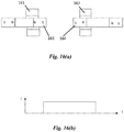
Fig. 16(a) illustrates the position of the poles of the magnets inside the solenoid, for minimizing the EMF; and -
Fig. 16(b) is a graph corresponding to the pole position ofFig. 16(a) , showing when the EMF ideally reaches down to zero. - The invention is concerned with a novel type of BLDC motor architecture, which leads to a major reduction of back EMF levels, thus yielding a motor capable of providing a constant torque value regardless of the angular velocity of the rotor. As a side benefit of the reduced back EMF, the overall applied voltage is nearly constant, and therefore no over-current peaks at start will occur.
- The cause of back EMF generation in prior-art BLDC, is the change in magnetic flux through the solenoids of the stator. This flux change is due to the spinning of the rotor, which produces both changes in the magnetic field strength present within the core of the solenoid (as a magnet of the rotor approaches a solenoid or moves away from it), as well as changes in the direction of the field lines with respect to the axis of the solenoids (a change in the component of the magnetic field crossing the core of the solenoid parallel to its axis produces a change in magnetic flux through it). During the circular movement of the magnets of the rotor, there is a change both in the distance between magnets and solenoids and in the direction of the magnetic field lines relative to the solenoids axis, which both result in flux changes through the solenoids. The architecture subject of the invention reduces the back EMF effect by reducing the above-mentioned flux changes.
- The motor architecture according to an example is schematically shown in
Fig. 3 , for the purpose of explaining the principle by which it operates. The stator architecture consists of a number of air-core solenoids 32 affixed to the motor housing, and whose axis of symmetry is aligned along acircular path 35. The basic rotor architecture consists of a number of permanent magnets 31 whose S-N axis is aligned with alternate polarity along the same circular path as the stator. The magnets are connected to each other with a high-permeability material therebetween to form a continuous circular ring as shown inFig. 5 . Alternatively, to represent background art that is useful for understanding the invention, but not forming part of the invention, the magnets may be mounted onto a circularflat base 35 and the space between them may be left open to air as inFig. 3 . The number of magnets may be larger, equal, or smaller than the number of the solenoids. - The rotor is supported by rotating mechanical bearings (not shown) and is free to rotate around the center of its circular shape while passing inside the core of the solenoids of the stator as shown in
Fig. 6 . The solenoids are electrically connected to the DC supply through a system of switches 33, preferably, but not limitatively, of the electronic type, which determines, at each instant, the polarity and the level of the voltage applied to each solenoid in the stator. The switches are controlled by an apparatus, preferably a microcontroller 36 with associated software, which determines at each instant the DC polarity applied to each solenoid (e.g., by inverting the DC connection to it), as well as the average DC level (e.g., by applying the DC supply voltage using Pulse Width Modulation (PWM)). The angular position of the rotor at each instant is detected by a system of sensors 34 (e.g., optical sensors or Hall-effect sensors). The sensor output is fed to the controller, which operates the switches according to the status of the rotor (i.e. angular position, speed and acceleration). - When a solenoid of the stator is energized, the nearby magnets of the rotor move along the circular path of the stator. The magnet is either pulled-in towards the solenoid core, or pushed-out from it, depending on the polarity of the switch associated with said solenoid, which determines the direction of flow of the current in the windings, and on the orientation of the magnets (N-N or S-S). In turn, the status of said switch is determined at each time by the controller, based on the angular position of the rotor detected by the sensors. Under the proper simultaneous operating sequence of the overall system of switches, it is possible to obtain a continuous smooth rotation of the rotor in either spinning direction. The motion of the rotor is then transferred to the load by means of a
mechanical gear 63 coupled to the rotor ring, as shown inFig. 6 . - Without wishing to be bound by any specific theory, the inventors believe that a possible mechanism that leads to the reduction of the back EMF, as a result of the novel motor architecture of the invention, may be as described below. As it may be readily appreciated from
Fig. 3 and the previous description, the motion of the magnets of the rotor with respect to the solenoids, is quasi-linear, namely, in direction of the axis of the solenoid. This is in contrast to the prior-art architecture in which the motion of magnets of the rotor is transversal, namely in a direction perpendicular to the axis of the solenoid. - As shown in
Fig. 4 , in the region between like-polarity poles (S-S or N-N) of two adjacent repelling magnets, 41 and 42, the transversal magnetic field is additive, while the axial magnetic field is subtractive. As a result, it can be shown that the (axial) magnetic field directed along the ring of the rotor in the region between the S-S or N-N poles of the magnets (and therefore in a direction along the solenoid axis) exhibits small variations between two magnets. While the transversal magnetic field contributes to the mechanical attraction/repulsion between the magnets and the solenoid (due to Lorentz's force law) it does not contribute to the magnetic flux through the solenoid. The (axial) magnetic field component, directed along the axis of the solenoid, is the one that contributes to the magnetic flux through the solenoid. However, the magnets of the rotor move in a direction collinear to the solenoid axis, and the field component in the collinear (axial) direction exhibits small variations in theregion 43 between two repulsing magnets. It follows that there will be a small change in magnetic flux during the transition, through the solenoid core, of any rotor section located between any two magnets, and therefore the back EMF generated during said transition will be small. Thus, if the solenoids are energized with the proper timing sequence, the back EMF effect opposing the DC supply voltage can be made small. - The invention will now be illustrated in detail with reference to an illustrative preferred embodiment. As will become apparent from the description to follow, the embodiment shown in the figures is only one of many possible alternative systems and it has been chosen for this description in view of its simplicity, it being understood that the invention is by no means limited to said embodiment.
- Reference is made to
Fig. 5 , which schematically shows a rotor architecture that is suitable for a circular, rotating brushless DC motor according to one embodiment of the invention. The rotor consists of a plurality of permanent magnets 51 (in the example of thefigure, 5 of them are shown) separated by ahigh permeability material 52, as may be, for instance, iron. As is seen in the figure every twomagnets 51 are separated by asegment 52 made of highly permeable material, and all the magnets and separating segments together form a ring-like structure. As explained above, it is also possible to represent background art that is useful for understanding the invention, but not forming part of the invention, to position the permanent magnets at fixed distances between them along the circular path and to allow air to separate them. Moreover, although it may be convenient to position the magnets at identical distances between them, it may also be possible to employ an asymmetric distribution of the magnets on the circumference on which they are disposed. - Looking now at
Fig. 6 , a general, schematic view of the motor according to this particular embodiment of the invention is seen in its assembled, operating condition. Details of the various constructive elements of the motor shown in this figure will be further illustrated with reference toFigs. 7-14 . As can be seen in the figure, therotor 61 rotates inside a plurality ofsolenoid assemblies 62. Power generated by the motor is transferred out, according to this particular embodiment, using agear 63. The moment of the rotor is supported bybearings 64, which may be of any suitable type. In the particular embodiment of this figure the assembly is positioned on abase 65. Also shown in the figure istoothed ring 101, which will be further discussed with reference toFig. 10 . -
Fig. 7 is a top view of the motor ofFig. 6 , showing the same elements, andFig. 8 is a side view of the same motor.Fig. 9 shows theupper ring 91, which is positioned aboverotor 61, and illustrates its structural relationship withbearings 64. The ring assembly associated withrotor 61 is shown inFig. 10 . According to the particular embodiment of the invention shown in this figure a number of rings are associated withrotor 61.Upper ring 91, already described with reference toFig. 9 , is positioned atop therotor 61, and arotor bottom ring 100 is positioned below the rotor which rests on it. Belowring 100toothed ring 101 is in geared cooperation withgear 63 ofFig. 6 . Abottom ring 102 is used to separate betweenbase 65 ofFig. 6 andtoothed ring 101. The assembly of the rings shown inFig. 10 is connected together so that all rings rotate together and power is transferred to gear 63. - The motor of
Fig. 6 is shown in exploded view inFig. 11 , using the same reference numbers as in the previous figures. As will be further discussed with reference toFig. 14 , thesolenoid housing 62 is conveniently made of two pieces, to make the assembly possible. -
Fig. 12 further illustrates the motor ofFig. 6 , with its central part being shown inFig. 12(a) . Two cross-sections are further shown in the figure, with Section A-A being an horizontal cross-section (Fig. 12 (b) ), and Section B-B being a vertical cross-section.Fig. 13 illustrates the positioning of thepermanent magnets 51 onring 100.Fig. 13(b) is a cross-section ofring 100 ofFig. 13(a) , taken along the D-D plane, showing amagnet 51 in place. According to this specific embodiment of the invention,lower protrusion 131 ofpermanent magnets 51 fits its female counterpart, i.e.groove 132 inlower ring 100, while itsupper protrusion 133 fits a similar groove in upper ring 91 (not shown in the figure).Fig. 13(c) showsmagnet 51 during its placement into the groove ofring 100, andFig. 13(d) is a perspective view of one such magnet already in place, as inFig. 13(b) . The additional magnets, as well as the separating high permeability material (52 ofFig. 5 ) are similarly located, and when all elements have been placed and rings 91 and 100 are put in place, the rotor assembly is ready to be positioned abovetoothed ring 101. - The various elements and their assembly is further illustrated in
Fig. 14 , where the various parts are identified by the same numerals as in the previous figures. Looking now atFigs. 3 and6 , to be understood thatsolenoid housings 62 will be provided with a coil around them, which in turn will be connected to a DC supply. - Turning now to
Fig. 15 , an alternative rotor architecture is illustrated, comprising a plurality of structures consisting of amagnet 151 which is fixed on a base (not shown), and is flanked by a high-permeability material 152, such as iron, on both sides. Gaps, indicated byarrow 153, are left between each such two structures. - As will be appreciated by the skilled person the above description of one specific embodiment of the invention is designed to illustrate the invention in simple terms, but is not intended to limit the invention in any way. Many modifications can be made to the motor of the invention. For instance, the number of permanent magnets in the rotor can be increased or decreased, many different mechanical arrangements can be provided in order to transmit the power generated by the motor, and the gear shown in the specific, illustrative embodiment described above is just one of many alternative structures. Moreover, many different ways and schemes for controlling the operation of the motor can be devised, including controllers, software and sensors, all of which is within the scope of the skilled person and therefore has not been described hereinabove for the sake of brevity.
Claims (14)
- A brushless DC motor capable of generating a substantially constant torque regardless of an angular velocity of its rotor, comprising:a) a circular rotor (61) comprising a plurality of circumferentially separated permanent magnets (31, 51); andb) a plurality of circumferentially spaced air core solenoids (32, 62) provided each around a static solenoid housing, wherein each of said solenoid housings is structured with a void portion through which said plurality of magnets can pass when said rotor rotates around its axis,wherein motion of the magnets with respect to the solenoids is quasi-linear in the direction of a solenoid axis,
wherein each of said plurality of solenoids is energized with a timing sequence to obtain a continuous smooth rotation of said rotor,
characterized in that said rotor further comprises a plurality of spacers (52) made of high magnetic permeability material, each of said spacers being interposed between two of said permanent magnets, to form a continuous rotor and to reduce variations in axial magnetic flux. - A brushless DC motor according to claim 1, wherein the number of solenoids (32, 62) equals the number of permanent magnets (31, 51).
- A brushless DC motor according to claim 1, wherein the number of solenoids (32, 62) is greater or smaller than the number of permanent magnets (31, 51).
- A brushless DC motor according to claim 1, further comprising one or more sensors (34) suitable to determine the position of the permanent magnets (31, 51) relative to the solenoids (32, 62).
- A brushless DC motor according to claim 4, further comprising a controller (36) suitable to supply current for the solenoids (32, 62) in response to a determination by one or more of the sensors (34) regarding a position of the magnets (31, 51) relative to the solenoids.
- A brushless DC motor according to claim 5, further comprising a plurality of switches (33) connected to a DC supply, for setting a polarity and level of voltage to be applied to each of the solenoids (32, 62) at any given instant, wherein the controller is adapted to control and energize the solenoids and invert the polarity and level of voltage to be applied to each of the solenoids at any given instant in response to the determination by one or more of the sensors (34) regarding the position of the magnets (31, 51) relative to the solenoids.
- A brushless DC motor according to claim 1, wherein the rotor (61) further comprises one or more structural ring elements (91, 100).
- A brushless DC motor according to claim 7, wherein the rotor (61) forms a ring.
- A brushless DC motor according to claim 8, wherein an inner surface of the rotor (61) is rotatably supported by a plurality of bearings (64).
- A brushless DC motor according to claim 1, wherein the rotor is mechanically connected to power-transmitting means (63, 101).
- A brushless DC motor according to claim 10, wherein the power-transmitting means comprise a toothed element (63, 101).
- A brushless DC motor according to claim 11, wherein the power-transmitting means comprise a gear (63) mechanically coupled to both the rotor (61) and a load, by which torque generated by the motor is transmitted to the load, and which is disposed externally to the rotor.
- A brushless DC motor according to claim 1, wherein the high magnetic permeability material from which each of the plurality of spacers (52) is made is iron.
- A method for operating a brushless DC motor, comprising the steps of:a) providing, on a circular structure (61), a plurality of circumferentially separated permanent magnets (31, 51);b) providing a plurality of circumferentially spaced air core solenoids (32, 62) each around a static solenoid housing, wherein each of said solenoid housings is structured with a void portion through which said plurality of magnets can pass when the circular structure rotates around its axis; andc) causing said circular structure to rotate by sequentially applying a polarity and voltage to said plurality of solenoids.d) determining at each instant the DC polarity applied to each solenoid, e.g. by inverting the DC connection to it, as well as the average DC level, e.g. by applying the DC supply voltage using Pulse Width Modulation (PWM), thus yielding a motor capable of providing a constant torque value regardless of the angular velocity of the rotor,characterized in that said circular structure is also provided with a plurality of spacers (52) made of high magnetic permeability material arranged such that each of said spacers is interposed between two of said permanent magnets to form a continuous structure, each of said plurality of spacers also being passable through said void portion when the circular structure rotates around its axis.
Applications Claiming Priority (2)
| Application Number | Priority Date | Filing Date | Title |
|---|---|---|---|
| IL218743A IL218743A0 (en) | 2012-03-20 | 2012-03-20 | A method of converting electromagnetic energy into mechanical one an apparatus for effecting this conversion |
| PCT/IL2013/050253 WO2013140400A1 (en) | 2012-03-20 | 2013-03-19 | Brushless dc motor |
Publications (3)
| Publication Number | Publication Date |
|---|---|
| EP2828960A1 EP2828960A1 (en) | 2015-01-28 |
| EP2828960A4 EP2828960A4 (en) | 2016-06-22 |
| EP2828960B1 true EP2828960B1 (en) | 2019-11-06 |
Family
ID=46614902
Family Applications (1)
| Application Number | Title | Priority Date | Filing Date |
|---|---|---|---|
| EP13764925.7A Active EP2828960B1 (en) | 2012-03-20 | 2013-03-19 | Brushless dc motor |
Country Status (18)
| Country | Link |
|---|---|
| US (1) | US9407129B2 (en) |
| EP (1) | EP2828960B1 (en) |
| JP (1) | JP6272293B2 (en) |
| KR (3) | KR20140142247A (en) |
| CN (1) | CN104272567B (en) |
| AU (1) | AU2013236987B2 (en) |
| CA (1) | CA2866788C (en) |
| CO (1) | CO7160033A2 (en) |
| EA (1) | EA028494B1 (en) |
| HK (2) | HK1205828A1 (en) |
| IL (3) | IL218743A0 (en) |
| MX (1) | MX338287B (en) |
| NZ (2) | NZ630243A (en) |
| PH (1) | PH12014501977A1 (en) |
| SG (1) | SG11201405633VA (en) |
| UA (1) | UA112571C2 (en) |
| WO (1) | WO2013140400A1 (en) |
| ZA (1) | ZA201506445B (en) |
Families Citing this family (17)
| Publication number | Priority date | Publication date | Assignee | Title |
|---|---|---|---|---|
| US10916999B2 (en) * | 2013-03-19 | 2021-02-09 | Intellitech Pty Ltd | Device and method for using a magnetic clutch in BLDC motors |
| EP3492765B1 (en) * | 2013-03-19 | 2020-07-15 | Intellitech Pty Ltd | A device and method for using a magnetic clutch in bldc motors |
| WO2016135725A2 (en) | 2015-02-28 | 2016-09-01 | Gavrielov Shmuel | Electric motor |
| GB2541360B (en) * | 2015-06-25 | 2022-04-06 | Intellitech Pty Ltd | Electric motor |
| GB2544720A (en) * | 2015-10-15 | 2017-05-31 | Vastech Holdings Ltd | Electric motor |
| GB2549694A (en) * | 2016-04-04 | 2017-11-01 | Vastech Holdings Ltd | Electric motor |
| GB201616560D0 (en) | 2016-09-29 | 2016-11-16 | Vastech Holdings Ltd | Electric motor having a diametric coil |
| CA2947812A1 (en) * | 2016-11-07 | 2018-05-07 | Jude Igwemezie | Magnet motor with electromagnetic drive |
| PL231784B1 (en) * | 2016-11-22 | 2019-04-30 | Andreas Lisson | Method for generation of electromotive force in the electric machine with rotating magnetic dipoles and the electric machine for execution of this method |
| FR3061613A1 (en) * | 2017-01-02 | 2018-07-06 | Michael Nadreau | TORQUE ELECTRICAL ROTATING MACHINE |
| GB2565267A (en) * | 2017-06-21 | 2019-02-13 | Vastech Holdings Ltd | Improved magnetic clutch assembly |
| GB201722054D0 (en) * | 2017-12-28 | 2018-02-14 | Vastech Holdings Ltd | Electric Motor |
| GB2571559A (en) * | 2018-03-01 | 2019-09-04 | Majoe Dennis | Electromagnetic machine |
| GB2574792B (en) * | 2018-04-27 | 2021-12-15 | Intellitech Pty Ltd | Rotationally balanced electric motor with air-core stator coils |
| US11509203B2 (en) | 2018-07-25 | 2022-11-22 | Moog Inc. | Claw-pole motor with rotor flux concentrators and poles and stator with solenoid coil and alternating stator teeth |
| US11581762B2 (en) | 2018-08-30 | 2023-02-14 | Moog Inc. | Claw pole motor with a ring coil and a meandering coil |
| RU2749049C1 (en) * | 2020-07-23 | 2021-06-03 | Валерий Федорович Коваленко | Dc electric motor with partial back emf |
Family Cites Families (13)
| Publication number | Priority date | Publication date | Assignee | Title |
|---|---|---|---|---|
| US4291248A (en) * | 1978-12-26 | 1981-09-22 | Rainbolt Research, Inc. | Electric motor |
| WO1991020120A1 (en) * | 1990-06-11 | 1991-12-26 | Peter Michael Nahirney | Direct current motor utilizing back electromotive force |
| JPH09182408A (en) * | 1995-12-27 | 1997-07-11 | Hitachi Metals Ltd | Linear motor |
| JPH1052007A (en) * | 1996-07-29 | 1998-02-20 | Shin Etsu Chem Co Ltd | Magnetized yoke |
| US6252317B1 (en) * | 1998-03-04 | 2001-06-26 | Edward N. Scheffer | Electric motor with ring rotor passing through coils |
| JP2000308324A (en) * | 1999-02-19 | 2000-11-02 | Hitachi Koki Co Ltd | Linear shuttle motor device |
| JP3658310B2 (en) * | 2000-11-16 | 2005-06-08 | 東芝テック株式会社 | PWM control circuit, electric blower and vacuum cleaner |
| JP2002369473A (en) | 2001-06-07 | 2002-12-20 | Nippon Steel Corp | Synchronous motor using permanent magnet |
| JP2009081982A (en) * | 2007-09-25 | 2009-04-16 | Satoshi Yamaguchi | Coil penetration type satellite motor |
| JP5358823B2 (en) * | 2008-06-25 | 2013-12-04 | リコーイメージング株式会社 | Rotary actuator |
| KR101011201B1 (en) * | 2008-11-04 | 2011-01-26 | 김영식 | Electromagnetic motor |
| US20110291504A1 (en) * | 2010-05-28 | 2011-12-01 | Michael Niedzialkowski | Rim Motor/Generator (RMG) |
| JP5153955B1 (en) * | 2012-07-03 | 2013-02-27 | 勝行 上林 | Energy converter |
-
2012
- 2012-03-20 IL IL218743A patent/IL218743A0/en unknown
-
2013
- 2013-03-19 MX MX2014010880A patent/MX338287B/en active IP Right Grant
- 2013-03-19 EA EA201491514A patent/EA028494B1/en not_active IP Right Cessation
- 2013-03-19 KR KR1020147026170A patent/KR20140142247A/en not_active Application Discontinuation
- 2013-03-19 WO PCT/IL2013/050253 patent/WO2013140400A1/en active Application Filing
- 2013-03-19 CA CA2866788A patent/CA2866788C/en active Active
- 2013-03-19 US US14/384,059 patent/US9407129B2/en active Active
- 2013-03-19 AU AU2013236987A patent/AU2013236987B2/en active Active
- 2013-03-19 UA UAA201409962A patent/UA112571C2/en unknown
- 2013-03-19 KR KR1020217006581A patent/KR20210029835A/en not_active Application Discontinuation
- 2013-03-19 KR KR1020197016398A patent/KR20190069598A/en not_active Application Discontinuation
- 2013-03-19 SG SG11201405633VA patent/SG11201405633VA/en unknown
- 2013-03-19 EP EP13764925.7A patent/EP2828960B1/en active Active
- 2013-03-19 JP JP2015501049A patent/JP6272293B2/en active Active
- 2013-03-19 NZ NZ630243A patent/NZ630243A/en not_active IP Right Cessation
- 2013-03-19 CN CN201380015485.5A patent/CN104272567B/en active Active
-
2014
- 2014-03-13 NZ NZ711789A patent/NZ711789A/en not_active IP Right Cessation
- 2014-09-04 PH PH12014501977A patent/PH12014501977A1/en unknown
- 2014-09-08 IL IL234534A patent/IL234534A/en active IP Right Grant
- 2014-10-15 CO CO14227947A patent/CO7160033A2/en unknown
-
2015
- 2015-07-02 HK HK15106273.8A patent/HK1205828A1/en not_active IP Right Cessation
- 2015-09-03 ZA ZA2015/06445A patent/ZA201506445B/en unknown
-
2016
- 2016-07-19 HK HK16108537.5A patent/HK1220502A1/en not_active IP Right Cessation
-
2020
- 2020-04-26 IL IL274247A patent/IL274247B/en unknown
Non-Patent Citations (1)
| Title |
|---|
| None * |
Also Published As
Similar Documents
| Publication | Publication Date | Title |
|---|---|---|
| EP2828960B1 (en) | Brushless dc motor | |
| EP2340602B1 (en) | Permanent magnet operating machine | |
| US8084913B2 (en) | DC motor with asymmetrical poles | |
| KR20140116258A (en) | Radial and Axial Flux Motor using Integrated Windings | |
| WO2013114286A2 (en) | Commutatorless and brushless dc machine with stationary armature and method of operating the same | |
| US20170250637A1 (en) | Axial Brushless DC Motor with Fractional and Hold Step Function | |
| EP2988402A1 (en) | Stepping motor | |
| JP6652987B2 (en) | DC electric motor | |
| US20190312490A1 (en) | Fault-tolerant motor | |
| US7375451B2 (en) | Electric motor having a permanent magnet rotor and a stator core of united poles | |
| EP3189584B1 (en) | Synchronous rotation motor or generator provided with diverse rotors and/or stators | |
| TWI449304B (en) | Permanent magnet operating machine | |
| US20150194869A1 (en) | Oscillating drive | |
| EP3012950A1 (en) | Three phase axial stepper motor with a direct current excitation | |
| WO2018150198A1 (en) | Electric motor | |
| CZ22888U1 (en) | Direct-current electric motor | |
| WO2017058129A1 (en) | An electromotor |
Legal Events
| Date | Code | Title | Description |
|---|---|---|---|
| PUAI | Public reference made under article 153(3) epc to a published international application that has entered the european phase |
Free format text: ORIGINAL CODE: 0009012 |
|
| 17P | Request for examination filed |
Effective date: 20141017 |
|
| AK | Designated contracting states |
Kind code of ref document: A1 Designated state(s): AL AT BE BG CH CY CZ DE DK EE ES FI FR GB GR HR HU IE IS IT LI LT LU LV MC MK MT NL NO PL PT RO RS SE SI SK SM TR |
|
| AX | Request for extension of the european patent |
Extension state: BA ME |
|
| RA4 | Supplementary search report drawn up and despatched (corrected) |
Effective date: 20160523 |
|
| RIC1 | Information provided on ipc code assigned before grant |
Ipc: H02K 41/035 20060101ALI20160517BHEP Ipc: H02K 21/12 20060101AFI20160517BHEP |
|
| STAA | Information on the status of an ep patent application or granted ep patent |
Free format text: STATUS: EXAMINATION IS IN PROGRESS |
|
| 17Q | First examination report despatched |
Effective date: 20171211 |
|
| RAP1 | Party data changed (applicant data changed or rights of an application transferred) |
Owner name: INTELLITECH PTY LTD |
|
| GRAP | Despatch of communication of intention to grant a patent |
Free format text: ORIGINAL CODE: EPIDOSNIGR1 |
|
| STAA | Information on the status of an ep patent application or granted ep patent |
Free format text: STATUS: GRANT OF PATENT IS INTENDED |
|
| INTG | Intention to grant announced |
Effective date: 20190517 |
|
| GRAS | Grant fee paid |
Free format text: ORIGINAL CODE: EPIDOSNIGR3 |
|
| GRAA | (expected) grant |
Free format text: ORIGINAL CODE: 0009210 |
|
| STAA | Information on the status of an ep patent application or granted ep patent |
Free format text: STATUS: THE PATENT HAS BEEN GRANTED |
|
| AK | Designated contracting states |
Kind code of ref document: B1 Designated state(s): AL AT BE BG CH CY CZ DE DK EE ES FI FR GB GR HR HU IE IS IT LI LT LU LV MC MK MT NL NO PL PT RO RS SE SI SK SM TR |
|
| AX | Request for extension of the european patent |
Extension state: BA ME |
|
| REG | Reference to a national code |
Ref country code: GB Ref legal event code: FG4D |
|
| REG | Reference to a national code |
Ref country code: CH Ref legal event code: EP Ref country code: AT Ref legal event code: REF Ref document number: 1200144 Country of ref document: AT Kind code of ref document: T Effective date: 20191115 |
|
| REG | Reference to a national code |
Ref country code: IE Ref legal event code: FG4D |
|
| REG | Reference to a national code |
Ref country code: DE Ref legal event code: R096 Ref document number: 602013062555 Country of ref document: DE |
|
| REG | Reference to a national code |
Ref country code: NL Ref legal event code: MP Effective date: 20191106 |
|
| REG | Reference to a national code |
Ref country code: LT Ref legal event code: MG4D |
|
| PG25 | Lapsed in a contracting state [announced via postgrant information from national office to epo] |
Ref country code: ES Free format text: LAPSE BECAUSE OF FAILURE TO SUBMIT A TRANSLATION OF THE DESCRIPTION OR TO PAY THE FEE WITHIN THE PRESCRIBED TIME-LIMIT Effective date: 20191106 Ref country code: LT Free format text: LAPSE BECAUSE OF FAILURE TO SUBMIT A TRANSLATION OF THE DESCRIPTION OR TO PAY THE FEE WITHIN THE PRESCRIBED TIME-LIMIT Effective date: 20191106 Ref country code: NL Free format text: LAPSE BECAUSE OF FAILURE TO SUBMIT A TRANSLATION OF THE DESCRIPTION OR TO PAY THE FEE WITHIN THE PRESCRIBED TIME-LIMIT Effective date: 20191106 Ref country code: BG Free format text: LAPSE BECAUSE OF FAILURE TO SUBMIT A TRANSLATION OF THE DESCRIPTION OR TO PAY THE FEE WITHIN THE PRESCRIBED TIME-LIMIT Effective date: 20200206 Ref country code: FI Free format text: LAPSE BECAUSE OF FAILURE TO SUBMIT A TRANSLATION OF THE DESCRIPTION OR TO PAY THE FEE WITHIN THE PRESCRIBED TIME-LIMIT Effective date: 20191106 Ref country code: GR Free format text: LAPSE BECAUSE OF FAILURE TO SUBMIT A TRANSLATION OF THE DESCRIPTION OR TO PAY THE FEE WITHIN THE PRESCRIBED TIME-LIMIT Effective date: 20200207 Ref country code: PL Free format text: LAPSE BECAUSE OF FAILURE TO SUBMIT A TRANSLATION OF THE DESCRIPTION OR TO PAY THE FEE WITHIN THE PRESCRIBED TIME-LIMIT Effective date: 20191106 Ref country code: PT Free format text: LAPSE BECAUSE OF FAILURE TO SUBMIT A TRANSLATION OF THE DESCRIPTION OR TO PAY THE FEE WITHIN THE PRESCRIBED TIME-LIMIT Effective date: 20200306 Ref country code: NO Free format text: LAPSE BECAUSE OF FAILURE TO SUBMIT A TRANSLATION OF THE DESCRIPTION OR TO PAY THE FEE WITHIN THE PRESCRIBED TIME-LIMIT Effective date: 20200206 Ref country code: LV Free format text: LAPSE BECAUSE OF FAILURE TO SUBMIT A TRANSLATION OF THE DESCRIPTION OR TO PAY THE FEE WITHIN THE PRESCRIBED TIME-LIMIT Effective date: 20191106 Ref country code: SE Free format text: LAPSE BECAUSE OF FAILURE TO SUBMIT A TRANSLATION OF THE DESCRIPTION OR TO PAY THE FEE WITHIN THE PRESCRIBED TIME-LIMIT Effective date: 20191106 |
|
| PG25 | Lapsed in a contracting state [announced via postgrant information from national office to epo] |
Ref country code: RS Free format text: LAPSE BECAUSE OF FAILURE TO SUBMIT A TRANSLATION OF THE DESCRIPTION OR TO PAY THE FEE WITHIN THE PRESCRIBED TIME-LIMIT Effective date: 20191106 Ref country code: HR Free format text: LAPSE BECAUSE OF FAILURE TO SUBMIT A TRANSLATION OF THE DESCRIPTION OR TO PAY THE FEE WITHIN THE PRESCRIBED TIME-LIMIT Effective date: 20191106 Ref country code: IS Free format text: LAPSE BECAUSE OF FAILURE TO SUBMIT A TRANSLATION OF THE DESCRIPTION OR TO PAY THE FEE WITHIN THE PRESCRIBED TIME-LIMIT Effective date: 20200306 |
|
| PG25 | Lapsed in a contracting state [announced via postgrant information from national office to epo] |
Ref country code: AL Free format text: LAPSE BECAUSE OF FAILURE TO SUBMIT A TRANSLATION OF THE DESCRIPTION OR TO PAY THE FEE WITHIN THE PRESCRIBED TIME-LIMIT Effective date: 20191106 |
|
| PG25 | Lapsed in a contracting state [announced via postgrant information from national office to epo] |
Ref country code: RO Free format text: LAPSE BECAUSE OF FAILURE TO SUBMIT A TRANSLATION OF THE DESCRIPTION OR TO PAY THE FEE WITHIN THE PRESCRIBED TIME-LIMIT Effective date: 20191106 Ref country code: CZ Free format text: LAPSE BECAUSE OF FAILURE TO SUBMIT A TRANSLATION OF THE DESCRIPTION OR TO PAY THE FEE WITHIN THE PRESCRIBED TIME-LIMIT Effective date: 20191106 Ref country code: DK Free format text: LAPSE BECAUSE OF FAILURE TO SUBMIT A TRANSLATION OF THE DESCRIPTION OR TO PAY THE FEE WITHIN THE PRESCRIBED TIME-LIMIT Effective date: 20191106 Ref country code: EE Free format text: LAPSE BECAUSE OF FAILURE TO SUBMIT A TRANSLATION OF THE DESCRIPTION OR TO PAY THE FEE WITHIN THE PRESCRIBED TIME-LIMIT Effective date: 20191106 |
|
| REG | Reference to a national code |
Ref country code: DE Ref legal event code: R097 Ref document number: 602013062555 Country of ref document: DE |
|
| REG | Reference to a national code |
Ref country code: AT Ref legal event code: MK05 Ref document number: 1200144 Country of ref document: AT Kind code of ref document: T Effective date: 20191106 |
|
| PG25 | Lapsed in a contracting state [announced via postgrant information from national office to epo] |
Ref country code: SK Free format text: LAPSE BECAUSE OF FAILURE TO SUBMIT A TRANSLATION OF THE DESCRIPTION OR TO PAY THE FEE WITHIN THE PRESCRIBED TIME-LIMIT Effective date: 20191106 Ref country code: SM Free format text: LAPSE BECAUSE OF FAILURE TO SUBMIT A TRANSLATION OF THE DESCRIPTION OR TO PAY THE FEE WITHIN THE PRESCRIBED TIME-LIMIT Effective date: 20191106 |
|
| PLBE | No opposition filed within time limit |
Free format text: ORIGINAL CODE: 0009261 |
|
| STAA | Information on the status of an ep patent application or granted ep patent |
Free format text: STATUS: NO OPPOSITION FILED WITHIN TIME LIMIT |
|
| 26N | No opposition filed |
Effective date: 20200807 |
|
| PG25 | Lapsed in a contracting state [announced via postgrant information from national office to epo] |
Ref country code: MC Free format text: LAPSE BECAUSE OF FAILURE TO SUBMIT A TRANSLATION OF THE DESCRIPTION OR TO PAY THE FEE WITHIN THE PRESCRIBED TIME-LIMIT Effective date: 20191106 |
|
| REG | Reference to a national code |
Ref country code: CH Ref legal event code: PL |
|
| PG25 | Lapsed in a contracting state [announced via postgrant information from national office to epo] |
Ref country code: SI Free format text: LAPSE BECAUSE OF FAILURE TO SUBMIT A TRANSLATION OF THE DESCRIPTION OR TO PAY THE FEE WITHIN THE PRESCRIBED TIME-LIMIT Effective date: 20191106 Ref country code: AT Free format text: LAPSE BECAUSE OF FAILURE TO SUBMIT A TRANSLATION OF THE DESCRIPTION OR TO PAY THE FEE WITHIN THE PRESCRIBED TIME-LIMIT Effective date: 20191106 |
|
| REG | Reference to a national code |
Ref country code: BE Ref legal event code: MM Effective date: 20200331 |
|
| PG25 | Lapsed in a contracting state [announced via postgrant information from national office to epo] |
Ref country code: LU Free format text: LAPSE BECAUSE OF NON-PAYMENT OF DUE FEES Effective date: 20200319 |
|
| PG25 | Lapsed in a contracting state [announced via postgrant information from national office to epo] |
Ref country code: LI Free format text: LAPSE BECAUSE OF NON-PAYMENT OF DUE FEES Effective date: 20200331 Ref country code: CH Free format text: LAPSE BECAUSE OF NON-PAYMENT OF DUE FEES Effective date: 20200331 Ref country code: IT Free format text: LAPSE BECAUSE OF FAILURE TO SUBMIT A TRANSLATION OF THE DESCRIPTION OR TO PAY THE FEE WITHIN THE PRESCRIBED TIME-LIMIT Effective date: 20191106 Ref country code: IE Free format text: LAPSE BECAUSE OF NON-PAYMENT OF DUE FEES Effective date: 20200319 |
|
| PG25 | Lapsed in a contracting state [announced via postgrant information from national office to epo] |
Ref country code: BE Free format text: LAPSE BECAUSE OF NON-PAYMENT OF DUE FEES Effective date: 20200331 |
|
| PG25 | Lapsed in a contracting state [announced via postgrant information from national office to epo] |
Ref country code: TR Free format text: LAPSE BECAUSE OF FAILURE TO SUBMIT A TRANSLATION OF THE DESCRIPTION OR TO PAY THE FEE WITHIN THE PRESCRIBED TIME-LIMIT Effective date: 20191106 Ref country code: MT Free format text: LAPSE BECAUSE OF FAILURE TO SUBMIT A TRANSLATION OF THE DESCRIPTION OR TO PAY THE FEE WITHIN THE PRESCRIBED TIME-LIMIT Effective date: 20191106 Ref country code: CY Free format text: LAPSE BECAUSE OF FAILURE TO SUBMIT A TRANSLATION OF THE DESCRIPTION OR TO PAY THE FEE WITHIN THE PRESCRIBED TIME-LIMIT Effective date: 20191106 |
|
| PG25 | Lapsed in a contracting state [announced via postgrant information from national office to epo] |
Ref country code: MK Free format text: LAPSE BECAUSE OF FAILURE TO SUBMIT A TRANSLATION OF THE DESCRIPTION OR TO PAY THE FEE WITHIN THE PRESCRIBED TIME-LIMIT Effective date: 20191106 |
|
| PGFP | Annual fee paid to national office [announced via postgrant information from national office to epo] |
Ref country code: FR Payment date: 20230327 Year of fee payment: 11 |
|
| PGFP | Annual fee paid to national office [announced via postgrant information from national office to epo] |
Ref country code: GB Payment date: 20230327 Year of fee payment: 11 Ref country code: DE Payment date: 20230329 Year of fee payment: 11 |