EP3086333A1 - Magnet manufacturing method and magnet - Google Patents
Magnet manufacturing method and magnet Download PDFInfo
- Publication number
- EP3086333A1 EP3086333A1 EP16165125.2A EP16165125A EP3086333A1 EP 3086333 A1 EP3086333 A1 EP 3086333A1 EP 16165125 A EP16165125 A EP 16165125A EP 3086333 A1 EP3086333 A1 EP 3086333A1
- Authority
- EP
- European Patent Office
- Prior art keywords
- magnetic powder
- powder
- particles
- magnetic
- magnet
- Prior art date
- Legal status (The legal status is an assumption and is not a legal conclusion. Google has not performed a legal analysis and makes no representation as to the accuracy of the status listed.)
- Withdrawn
Links
- 238000004519 manufacturing process Methods 0.000 title claims abstract description 33
- 239000006247 magnetic powder Substances 0.000 claims abstract description 141
- 239000002245 particle Substances 0.000 claims abstract description 117
- 238000000465 moulding Methods 0.000 claims abstract description 70
- 238000010438 heat treatment Methods 0.000 claims abstract description 32
- 150000001875 compounds Chemical class 0.000 claims abstract description 22
- 238000009826 distribution Methods 0.000 claims abstract description 19
- 238000000354 decomposition reaction Methods 0.000 claims abstract description 12
- 239000000696 magnetic material Substances 0.000 claims abstract description 12
- 239000000843 powder Substances 0.000 claims description 106
- 239000000314 lubricant Substances 0.000 claims description 55
- 239000000203 mixture Substances 0.000 claims description 16
- 239000007787 solid Substances 0.000 claims description 7
- 238000002844 melting Methods 0.000 claims description 4
- 230000008018 melting Effects 0.000 claims description 4
- 239000011248 coating agent Substances 0.000 description 15
- 238000000576 coating method Methods 0.000 description 15
- 238000002156 mixing Methods 0.000 description 15
- 238000010586 diagram Methods 0.000 description 14
- 239000011812 mixed powder Substances 0.000 description 13
- 229910052761 rare earth metal Inorganic materials 0.000 description 9
- 230000004907 flux Effects 0.000 description 8
- 229920005989 resin Polymers 0.000 description 8
- 239000011347 resin Substances 0.000 description 8
- 238000005304 joining Methods 0.000 description 7
- 238000007747 plating Methods 0.000 description 7
- 229910045601 alloy Inorganic materials 0.000 description 6
- 239000000956 alloy Substances 0.000 description 6
- QVGXLLKOCUKJST-UHFFFAOYSA-N atomic oxygen Chemical compound [O] QVGXLLKOCUKJST-UHFFFAOYSA-N 0.000 description 6
- 238000007772 electroless plating Methods 0.000 description 6
- 229910052760 oxygen Inorganic materials 0.000 description 6
- 239000001301 oxygen Substances 0.000 description 6
- 230000001590 oxidative effect Effects 0.000 description 5
- 229910000920 Fe16N2 Inorganic materials 0.000 description 4
- 229910052692 Dysprosium Inorganic materials 0.000 description 3
- 229910001199 N alloy Inorganic materials 0.000 description 3
- 235000021355 Stearic acid Nutrition 0.000 description 3
- KBQHZAAAGSGFKK-UHFFFAOYSA-N dysprosium atom Chemical compound [Dy] KBQHZAAAGSGFKK-UHFFFAOYSA-N 0.000 description 3
- 230000000694 effects Effects 0.000 description 3
- 238000009713 electroplating Methods 0.000 description 3
- 239000011521 glass Substances 0.000 description 3
- 239000007788 liquid Substances 0.000 description 3
- 239000010687 lubricating oil Substances 0.000 description 3
- 238000005259 measurement Methods 0.000 description 3
- 229910052751 metal Inorganic materials 0.000 description 3
- 239000002184 metal Substances 0.000 description 3
- 238000000034 method Methods 0.000 description 3
- QIQXTHQIDYTFRH-UHFFFAOYSA-N octadecanoic acid Chemical compound CCCCCCCCCCCCCCCCCC(O)=O QIQXTHQIDYTFRH-UHFFFAOYSA-N 0.000 description 3
- OQCDKBAXFALNLD-UHFFFAOYSA-N octadecanoic acid Natural products CCCCCCCC(C)CCCCCCCCC(O)=O OQCDKBAXFALNLD-UHFFFAOYSA-N 0.000 description 3
- 239000008117 stearic acid Substances 0.000 description 3
- 239000000654 additive Substances 0.000 description 2
- 230000000996 additive effect Effects 0.000 description 2
- 230000006835 compression Effects 0.000 description 2
- 238000007906 compression Methods 0.000 description 2
- 229910052802 copper Inorganic materials 0.000 description 2
- 230000007797 corrosion Effects 0.000 description 2
- 238000005260 corrosion Methods 0.000 description 2
- 238000000227 grinding Methods 0.000 description 2
- 239000006249 magnetic particle Substances 0.000 description 2
- 238000000691 measurement method Methods 0.000 description 2
- 229910001172 neodymium magnet Inorganic materials 0.000 description 2
- 229910052759 nickel Inorganic materials 0.000 description 2
- 239000002994 raw material Substances 0.000 description 2
- 230000008707 rearrangement Effects 0.000 description 2
- 229910052709 silver Inorganic materials 0.000 description 2
- 238000005245 sintering Methods 0.000 description 2
- 238000003756 stirring Methods 0.000 description 2
- OKTJSMMVPCPJKN-UHFFFAOYSA-N Carbon Chemical compound [C] OKTJSMMVPCPJKN-UHFFFAOYSA-N 0.000 description 1
- 229910052684 Cerium Inorganic materials 0.000 description 1
- 102000002322 Egg Proteins Human genes 0.000 description 1
- 108010000912 Egg Proteins Proteins 0.000 description 1
- 229910052693 Europium Inorganic materials 0.000 description 1
- YCKRFDGAMUMZLT-UHFFFAOYSA-N Fluorine atom Chemical compound [F] YCKRFDGAMUMZLT-UHFFFAOYSA-N 0.000 description 1
- 229910052779 Neodymium Inorganic materials 0.000 description 1
- 229910052777 Praseodymium Inorganic materials 0.000 description 1
- 229910052772 Samarium Inorganic materials 0.000 description 1
- 238000013459 approach Methods 0.000 description 1
- 239000011230 binding agent Substances 0.000 description 1
- 238000004364 calculation method Methods 0.000 description 1
- 229910052799 carbon Inorganic materials 0.000 description 1
- 229910052804 chromium Inorganic materials 0.000 description 1
- 238000000748 compression moulding Methods 0.000 description 1
- 230000007423 decrease Effects 0.000 description 1
- 210000003278 egg shell Anatomy 0.000 description 1
- 239000010419 fine particle Substances 0.000 description 1
- 229910052731 fluorine Inorganic materials 0.000 description 1
- 239000011737 fluorine Substances 0.000 description 1
- 229910052737 gold Inorganic materials 0.000 description 1
- 230000005484 gravity Effects 0.000 description 1
- 229910052747 lanthanoid Inorganic materials 0.000 description 1
- 150000002602 lanthanoids Chemical class 0.000 description 1
- 229910052746 lanthanum Inorganic materials 0.000 description 1
- 239000000463 material Substances 0.000 description 1
- 239000003960 organic solvent Substances 0.000 description 1
- 238000002360 preparation method Methods 0.000 description 1
- 238000010791 quenching Methods 0.000 description 1
- 230000000171 quenching effect Effects 0.000 description 1
- 150000002910 rare earth metals Chemical class 0.000 description 1
- 230000009467 reduction Effects 0.000 description 1
- 230000035939 shock Effects 0.000 description 1
- 229920002050 silicone resin Polymers 0.000 description 1
- 239000000344 soap Substances 0.000 description 1
- 230000002195 synergetic effect Effects 0.000 description 1
- 229920002803 thermoplastic polyurethane Polymers 0.000 description 1
- 229910052718 tin Inorganic materials 0.000 description 1
- 229910052725 zinc Inorganic materials 0.000 description 1
- 239000011701 zinc Substances 0.000 description 1
- XOOUIPVCVHRTMJ-UHFFFAOYSA-L zinc stearate Chemical compound [Zn+2].CCCCCCCCCCCCCCCCCC([O-])=O.CCCCCCCCCCCCCCCCCC([O-])=O XOOUIPVCVHRTMJ-UHFFFAOYSA-L 0.000 description 1
Images


Classifications
-
- H—ELECTRICITY
- H01—ELECTRIC ELEMENTS
- H01F—MAGNETS; INDUCTANCES; TRANSFORMERS; SELECTION OF MATERIALS FOR THEIR MAGNETIC PROPERTIES
- H01F41/00—Apparatus or processes specially adapted for manufacturing or assembling magnets, inductances or transformers; Apparatus or processes specially adapted for manufacturing materials characterised by their magnetic properties
- H01F41/02—Apparatus or processes specially adapted for manufacturing or assembling magnets, inductances or transformers; Apparatus or processes specially adapted for manufacturing materials characterised by their magnetic properties for manufacturing cores, coils, or magnets
- H01F41/0253—Apparatus or processes specially adapted for manufacturing or assembling magnets, inductances or transformers; Apparatus or processes specially adapted for manufacturing materials characterised by their magnetic properties for manufacturing cores, coils, or magnets for manufacturing permanent magnets
- H01F41/0266—Moulding; Pressing
-
- H—ELECTRICITY
- H01—ELECTRIC ELEMENTS
- H01F—MAGNETS; INDUCTANCES; TRANSFORMERS; SELECTION OF MATERIALS FOR THEIR MAGNETIC PROPERTIES
- H01F1/00—Magnets or magnetic bodies characterised by the magnetic materials therefor; Selection of materials for their magnetic properties
- H01F1/01—Magnets or magnetic bodies characterised by the magnetic materials therefor; Selection of materials for their magnetic properties of inorganic materials
- H01F1/03—Magnets or magnetic bodies characterised by the magnetic materials therefor; Selection of materials for their magnetic properties of inorganic materials characterised by their coercivity
- H01F1/032—Magnets or magnetic bodies characterised by the magnetic materials therefor; Selection of materials for their magnetic properties of inorganic materials characterised by their coercivity of hard-magnetic materials
- H01F1/04—Magnets or magnetic bodies characterised by the magnetic materials therefor; Selection of materials for their magnetic properties of inorganic materials characterised by their coercivity of hard-magnetic materials metals or alloys
- H01F1/047—Alloys characterised by their composition
- H01F1/053—Alloys characterised by their composition containing rare earth metals
- H01F1/055—Alloys characterised by their composition containing rare earth metals and magnetic transition metals, e.g. SmCo5
- H01F1/059—Alloys characterised by their composition containing rare earth metals and magnetic transition metals, e.g. SmCo5 and Va elements, e.g. Sm2Fe17N2
-
- B—PERFORMING OPERATIONS; TRANSPORTING
- B22—CASTING; POWDER METALLURGY
- B22F—WORKING METALLIC POWDER; MANUFACTURE OF ARTICLES FROM METALLIC POWDER; MAKING METALLIC POWDER; APPARATUS OR DEVICES SPECIALLY ADAPTED FOR METALLIC POWDER
- B22F1/00—Metallic powder; Treatment of metallic powder, e.g. to facilitate working or to improve properties
- B22F1/05—Metallic powder characterised by the size or surface area of the particles
- B22F1/052—Metallic powder characterised by the size or surface area of the particles characterised by a mixture of particles of different sizes or by the particle size distribution
-
- B—PERFORMING OPERATIONS; TRANSPORTING
- B22—CASTING; POWDER METALLURGY
- B22F—WORKING METALLIC POWDER; MANUFACTURE OF ARTICLES FROM METALLIC POWDER; MAKING METALLIC POWDER; APPARATUS OR DEVICES SPECIALLY ADAPTED FOR METALLIC POWDER
- B22F1/00—Metallic powder; Treatment of metallic powder, e.g. to facilitate working or to improve properties
- B22F1/10—Metallic powder containing lubricating or binding agents; Metallic powder containing organic material
-
- H—ELECTRICITY
- H01—ELECTRIC ELEMENTS
- H01F—MAGNETS; INDUCTANCES; TRANSFORMERS; SELECTION OF MATERIALS FOR THEIR MAGNETIC PROPERTIES
- H01F1/00—Magnets or magnetic bodies characterised by the magnetic materials therefor; Selection of materials for their magnetic properties
- H01F1/01—Magnets or magnetic bodies characterised by the magnetic materials therefor; Selection of materials for their magnetic properties of inorganic materials
- H01F1/03—Magnets or magnetic bodies characterised by the magnetic materials therefor; Selection of materials for their magnetic properties of inorganic materials characterised by their coercivity
- H01F1/032—Magnets or magnetic bodies characterised by the magnetic materials therefor; Selection of materials for their magnetic properties of inorganic materials characterised by their coercivity of hard-magnetic materials
- H01F1/04—Magnets or magnetic bodies characterised by the magnetic materials therefor; Selection of materials for their magnetic properties of inorganic materials characterised by their coercivity of hard-magnetic materials metals or alloys
- H01F1/047—Alloys characterised by their composition
- H01F1/053—Alloys characterised by their composition containing rare earth metals
-
- H—ELECTRICITY
- H01—ELECTRIC ELEMENTS
- H01F—MAGNETS; INDUCTANCES; TRANSFORMERS; SELECTION OF MATERIALS FOR THEIR MAGNETIC PROPERTIES
- H01F1/00—Magnets or magnetic bodies characterised by the magnetic materials therefor; Selection of materials for their magnetic properties
- H01F1/01—Magnets or magnetic bodies characterised by the magnetic materials therefor; Selection of materials for their magnetic properties of inorganic materials
- H01F1/03—Magnets or magnetic bodies characterised by the magnetic materials therefor; Selection of materials for their magnetic properties of inorganic materials characterised by their coercivity
- H01F1/032—Magnets or magnetic bodies characterised by the magnetic materials therefor; Selection of materials for their magnetic properties of inorganic materials characterised by their coercivity of hard-magnetic materials
- H01F1/04—Magnets or magnetic bodies characterised by the magnetic materials therefor; Selection of materials for their magnetic properties of inorganic materials characterised by their coercivity of hard-magnetic materials metals or alloys
- H01F1/047—Alloys characterised by their composition
- H01F1/053—Alloys characterised by their composition containing rare earth metals
- H01F1/055—Alloys characterised by their composition containing rare earth metals and magnetic transition metals, e.g. SmCo5
- H01F1/0551—Alloys characterised by their composition containing rare earth metals and magnetic transition metals, e.g. SmCo5 in the form of particles, e.g. rapid quenched powders or ribbon flakes
-
- H—ELECTRICITY
- H01—ELECTRIC ELEMENTS
- H01F—MAGNETS; INDUCTANCES; TRANSFORMERS; SELECTION OF MATERIALS FOR THEIR MAGNETIC PROPERTIES
- H01F1/00—Magnets or magnetic bodies characterised by the magnetic materials therefor; Selection of materials for their magnetic properties
- H01F1/01—Magnets or magnetic bodies characterised by the magnetic materials therefor; Selection of materials for their magnetic properties of inorganic materials
- H01F1/03—Magnets or magnetic bodies characterised by the magnetic materials therefor; Selection of materials for their magnetic properties of inorganic materials characterised by their coercivity
- H01F1/032—Magnets or magnetic bodies characterised by the magnetic materials therefor; Selection of materials for their magnetic properties of inorganic materials characterised by their coercivity of hard-magnetic materials
- H01F1/04—Magnets or magnetic bodies characterised by the magnetic materials therefor; Selection of materials for their magnetic properties of inorganic materials characterised by their coercivity of hard-magnetic materials metals or alloys
- H01F1/047—Alloys characterised by their composition
- H01F1/053—Alloys characterised by their composition containing rare earth metals
- H01F1/055—Alloys characterised by their composition containing rare earth metals and magnetic transition metals, e.g. SmCo5
- H01F1/0555—Alloys characterised by their composition containing rare earth metals and magnetic transition metals, e.g. SmCo5 pressed, sintered or bonded together
- H01F1/0556—Alloys characterised by their composition containing rare earth metals and magnetic transition metals, e.g. SmCo5 pressed, sintered or bonded together pressed
-
- H—ELECTRICITY
- H01—ELECTRIC ELEMENTS
- H01F—MAGNETS; INDUCTANCES; TRANSFORMERS; SELECTION OF MATERIALS FOR THEIR MAGNETIC PROPERTIES
- H01F1/00—Magnets or magnetic bodies characterised by the magnetic materials therefor; Selection of materials for their magnetic properties
- H01F1/01—Magnets or magnetic bodies characterised by the magnetic materials therefor; Selection of materials for their magnetic properties of inorganic materials
- H01F1/03—Magnets or magnetic bodies characterised by the magnetic materials therefor; Selection of materials for their magnetic properties of inorganic materials characterised by their coercivity
- H01F1/032—Magnets or magnetic bodies characterised by the magnetic materials therefor; Selection of materials for their magnetic properties of inorganic materials characterised by their coercivity of hard-magnetic materials
- H01F1/04—Magnets or magnetic bodies characterised by the magnetic materials therefor; Selection of materials for their magnetic properties of inorganic materials characterised by their coercivity of hard-magnetic materials metals or alloys
- H01F1/06—Magnets or magnetic bodies characterised by the magnetic materials therefor; Selection of materials for their magnetic properties of inorganic materials characterised by their coercivity of hard-magnetic materials metals or alloys in the form of particles, e.g. powder
-
- H—ELECTRICITY
- H01—ELECTRIC ELEMENTS
- H01F—MAGNETS; INDUCTANCES; TRANSFORMERS; SELECTION OF MATERIALS FOR THEIR MAGNETIC PROPERTIES
- H01F1/00—Magnets or magnetic bodies characterised by the magnetic materials therefor; Selection of materials for their magnetic properties
- H01F1/01—Magnets or magnetic bodies characterised by the magnetic materials therefor; Selection of materials for their magnetic properties of inorganic materials
- H01F1/03—Magnets or magnetic bodies characterised by the magnetic materials therefor; Selection of materials for their magnetic properties of inorganic materials characterised by their coercivity
- H01F1/032—Magnets or magnetic bodies characterised by the magnetic materials therefor; Selection of materials for their magnetic properties of inorganic materials characterised by their coercivity of hard-magnetic materials
- H01F1/04—Magnets or magnetic bodies characterised by the magnetic materials therefor; Selection of materials for their magnetic properties of inorganic materials characterised by their coercivity of hard-magnetic materials metals or alloys
- H01F1/06—Magnets or magnetic bodies characterised by the magnetic materials therefor; Selection of materials for their magnetic properties of inorganic materials characterised by their coercivity of hard-magnetic materials metals or alloys in the form of particles, e.g. powder
- H01F1/08—Magnets or magnetic bodies characterised by the magnetic materials therefor; Selection of materials for their magnetic properties of inorganic materials characterised by their coercivity of hard-magnetic materials metals or alloys in the form of particles, e.g. powder pressed, sintered, or bound together
Definitions
- the invention relates to a magnet manufacturing method and a magnet.
- JP 2007-39794 A describes a magnet containing an Nd-Fe-B alloy or an Sm-Fe-N alloy. JP 2007-39794 further discloses that a soft magnetic metal is mixed with the above-described alloy and that the mixture is molded under pressure and sintered.
- JP 2012-69962 A discloses that an R-Fe-N-H-based magnetic material and soft magnetic powder are mixed together and that the mixture is compacted and solidified by impact compression using an underwater shock wave and that after the impact compression, a residual temperature is kept equal to or lower than a decomposition temperature of the magnetic material.
- This magnet contains no binder such as resin.
- JP 2005-223263 A discloses that a rare-earth permanent magnet is manufactured by forming an oxide film on Sm-Fe-N-based compound powder, then preliminarily compression-molding the Sm-Fe-N-based compound powder into a predetermined shape in a non-oxidizing atmosphere, and compacting the resultant compound at 350 to 500°C in the non-oxidizing atmosphere.
- JP 2005-223263 discloses that the Sm-Fe-N-based magnet can thus be manufactured at a temperature lower than the decomposition temperature.
- JP S62-206801 A discloses that a stearic acid is mixed with alloy powder to cover powder particles with the stearic acid and that the powder particles are then compression-molded and then sintered.
- JP 2015-8200 A discloses that a magnet is manufactured by executing a pressurizing step of forming a primary molding by pressurizing magnetic powder of a hard magnetic material a plurality of times using a mold, the magnetic powder being formed using an R-Fe-N-based compound containing a rare earth element as R or an Fe-N-based compound, and then forming a secondary molding by heating the magnetic powder at a temperature lower than the decomposition temperature of the magnetic powder to join surfaces of adjacent magnetic particles.
- dysprosium which is expensive and rare, needs to be used for the magnet containing the Nd-Fe-B alloy.
- sintering is difficult due to the low decomposition temperature of the Sm-Fe-N alloy.
- the sintering involves temperatures equal to or higher than the decomposition temperature, leading to decomposition of the alloy to preclude the resultant magnet from demonstrating its performance as a magnet.
- Sm-Fe-N-based magnets are typically joined together with a bond such as resin.
- the use of the bond such as resin reduces the density of the magnet, causing a reduction in residual magnetic flux density.
- the magnetic particles are not sintered, and thus, gaps remain between particles of the powder in the molded magnet.
- the molded magnet of unsintered magnetic powder has lower density than the molded magnet of sintered magnetic powder.
- the molded magnet of the unsintered magnetic powder has lower residual magnetic flux density than that of the sintered magnetic powder.
- JP 2015-8200 A which describes a technique dealing with the above-described problem, when the primary molding has a complicated shape, a high pressurizing pressure cannot be applied depending on the configuration of the mold. In other words, an increase in density is limited depending on the shape of the molding. Then, enhancement of the residual magnetic flux density of the manufactured magnet is also limited.
- An object of the invention is to provide a magnet manufacturing method and a magnet that allow a high residual magnetic flux density to be obtained without the use of a bond.
- a magnet manufacturing method includes preparing magnetic powder of a hard magnetic material, which includes one or more of an Fe-N-based compound and an R-Fe-N-based compound (R: rare earth element), pressurizing and molding the magnetic powder at a pressure equal to or lower than a fracture pressure at which particles of the magnetic powder are destroyed in order to obtain a primary molding, and heating the primary molding at a temperature lower than a decomposition temperature of the magnetic powder.
- the magnetic powder has at least two peaks in a particle size distribution.
- a compound that includes one or more of the Fe-N-based compound and the R-Fe-N-based compound is used as the magnetic powder of the hard magnetic material.
- a magnet can be inexpensively manufactured.
- the magnetic powder prepared exhibits at least two peaks when the particle size distribution is measured.
- the magnetic powder is pressurized at the pressure equal to or lower than the fracture pressure to allow particles of the magnetic powder that have small particle sizes to be fitted between gaps defined between particles of the magnetic powder that have large particle sizes.
- a dense primary molding with reduced gaps is obtained.
- the primary molding is heated to join surfaces of the particles of the magnetic powder together to form a secondary molding.
- the secondary molding is configured such that the magnetic powder particles are joined together in the dense primary molding with the filled gaps.
- the manufacturing method according to this aspect allows manufacture of a dense magnet with filled gaps.
- the manufacturing method according to this aspect further allows a dense magnet with filled gaps to be manufactured in manufacture of a magnet that has a complicated shape and that makes an increase in molding pressure difficult.
- the manufacturing method in this aspect is particularly effective in manufacturing a magnet with a complicated shape.
- FIG. 1 is a diagram illustrating steps of the magnet manufacturing method of a first embodiment.
- magnetic powder 1 of a hard magnetic material as a raw material for a magnet is prepared.
- a compound which includes one or more of an Fe-N-based compound and an R-Fe-N-based compound.
- a rare earth element represented by R is preferably an element that is known as a so-called rare earth element and that is other than Dy.
- light rare earth elements are preferable, and among the light rare earth elements, Sm is suitable.
- the light rare earth elements described herein refer to elements included in lanthanoids and each having a smaller atomic weight than Gd, that is, La, Ce, Pr, Nd, Pm, Sm, and Eu.
- a specific composition of the magnetic powder 1 is not limited as long as the magnetic powder 1 is an Fe-N-based compound or an R-Fe-N-based compound. Powder of Sm 2 Fe 17 N 3 or Fe 16 N 2 is suitably used.
- the magnetic powder 1 prepared exhibits two peaks (a plurality of peaks) as depicted in FIG. 2 when a particle size distribution is measured.
- a measurement method for the particle size distribution is not limited. Any measurement method (calculation method) may be used which allows particle size and frequency to be understood.
- the particle size distribution of the magnetic powder 1 in the present embodiment illustrated in FIG. 2 has two peaks at particle sizes of 0.75 ⁇ m and 4 ⁇ m.
- a manufacturing method for the magnetic powder 1 in the present embodiment is not limited as long as the magnetic powder 1 has the particle size distribution depicted in FIG. 2 .
- the magnetic powder 1 is obtained by mixing fine powder 11 that exhibits a particle size distribution depicted in FIG. 3 and that has an average particle size (D50) of 0.75 ⁇ m with coarse powder 12 that exhibits a particle size distribution depicted in FIG. 4 and that has an average particle size (D50) of 4 ⁇ m.
- the fine powder 11 and the coarse powder 12 each have sharp peaks in the particle size distribution.
- the particle size distribution peaks of the fine powder 11 and the coarse powder 12 do not substantially overlap.
- the ratio of the particle size of fine powder 11 to the particle size of the coarse powder 12 preferably falls within a range from 1:4 to 1:7.
- the ratio of the particle sizes is within this range, particles of the fine powder 11 are densely placed in gaps between particles of the coarse powder 12.
- each of the particles of the fine powder 11 is excessively small compared to the corresponding gap between the particles of the coarse powder 12.
- gaps remain between the particles of the coarse powder 12.
- the ratio of the particle sizes is higher than 1:7, each of the particles of the fine powder 11 is larger than the corresponding gap between the particles of the coarse powder 12.
- the fine powder 11 hinders the particles of the coarse powder 12 from being proximate to one another. In other words, the gaps between the particles of the coarse powder 12 are enlarged.
- the volume ratio of the fine powder 11 to the coarse powder 12 preferably falls within a range from 10:90 to 40:60.
- a volume ratio within this range allows the particles of the fine powder 11 to be densely placed in the gaps between the particles of the coarse powder 12.
- a volume ratio of less than 10:90 leads to few particles of the fine powder 11 with respect to the gaps between the particles of the coarse powder 12.
- gaps remain between the particles of the coarse powder 12.
- a volume ratio of more than 40:60 leads to many particles of the fine powder 11 with respect to the gaps between the particles of the coarse powder 12.
- the fine powder 11 is placed between the particles of the coarse powder 12.
- the particles of the fine powder 11 hinder the particles of the coarse powder 12 from being proximate to one another. In other words, the gaps between the particles of the coarse powder 12 are enlarged.
- FIG. 5 illustrates a relationship between the mixture ratio (volume ratio) of the fine powder 11 to the coarse powder 12 in the magnetic powder 1 in FIG. 2 and the density of a primary molding obtained in a pressurizing step described below (step S4) in the present embodiment.
- FIG. 5 indicates that a dense primary molding is obtained by setting the volume ratio of the fine powder 11 to the coarse powder 12 to 10:90 to 40:60.
- the volume ratio of the fine powder 11 to the coarse powder is more preferably 10:90 to 20:80.
- the magnetic powder in the present embodiment is obtained by mixing the fine powder 11 and the coarse powder 12 such that the volume ratio of the fine powder 11 to the coarse powder 12 is 15:85. This ratio is most preferable.
- the magnetic powder 1 in the present embodiment is formed by mixing a plurality of types of powder with the same compositions (fine powder 11 and coarse powder 12) but may be formed by mixing a plurality of types of powder with different compositions.
- the magnetic powder 1 prepared in the present embodiment preferably contains an even mixture of the fine powder 11 and the coarse powder 12. That is, the magnetic powder 1 is preferably obtained by mixing and stirring the fine powder 11 and the coarse powder 12. The mixture of the fine powder 11 and the coarse powder 12 may be performed in step S3 described below in conjunction with mixing and stirring of a lubricant and the magnetic powder 1.
- the particle size (average particle size: D50) of the particles of the coarse powder 12 is preferably approximately 2 ⁇ m to 5 ⁇ m and more preferably approximately 3 ⁇ m to 4 ⁇ m.
- the particle size (average particle size: D50) of the particles of the fine powder 11 is preferably approximately 0.29 ⁇ m to 1.25 ⁇ m and more preferably approximately 0.43 ⁇ m to 1.00 ⁇ m.
- step S2 in FIG. 1 the magnetic powder 1 prepared in step S1 and a lubricant 2 (solid lubricant powder) that is powdery at normal temperature are prepared.
- Metal soap powder is used as the lubricant 2.
- powder of stearic acid-based metal such as zinc stearate is used.
- the particle size of the lubricant 2 is not limited but may be approximately 10 ⁇ m. In other words, the lubricant 2 has a larger average particle size than the coarse powder 12 in the magnetic powder 1.
- the lubricant 2 has a smaller specific gravity than the magnetic powder 1. Setting a somewhat large initial size for the lubricant 2 enables each particle of the lubricant 2 to have a large mass. This prevents the lubricant 2 from being stirred up in step S3 described below when the lubricant 2 is mixed with the magnetic powder 1.
- step S3 in FIG. 1 the magnetic powder 1 and the lubricant 2 prepared in the step S2 are mixed together while being ground.
- a mixture ratio between the magnetic powder 1 and the lubricant 2 can be optionally set.
- the preferable mixture ratio between the magnetic powder 1 and the lubricant 2 is such that, in volume percentage, the magnetic powder is 80 to 90 vol%, whereas the lubricant 2 is 5 to 15 vol%.
- an additive may be added. Examples of the additive include organic solvents that disappear as a result of subsequent heating.
- any method may be used to mix the magnetic powder 1 and the lubricant 2 together as long as the method allows the magnetic powder 1 and the lubricant 2 to be mixed together while being ground.
- the magnetic powder 1 fine powder 11 and coarse powder 12
- the lubricant 2 are mixed together while being ground as depicted in a schematic diagram in FIG. 6 .
- Mixing and simultaneously grinding the magnetic powder 1 and the lubricant 2 fractionizes the lubricant 2, which has a low binding strength, to reduce the general particle size of the lubricant 2, as depicted in a schematic diagram in FIG. 7 .
- particles of the lubricant 2 present at the end of the mixing step have different particle sizes.
- grinding is performed at a pressure at which the magnetic powder 1 is prevented from being destroyed.
- the mixed powder of the magnetic powder 1 and the lubricant 2 can contain reduced massive portions formed only of the magnetic powder 1 and have a reduced particle size of the lubricant 2.
- fine particles 2 and 2' of the lubricant resulting from crushing can be present at positions proximate to each particle of the magnetic powder 1.
- step S4 in FIG. 1 the mixed powder of the magnetic powder 1 and the lubricant 2 is pressurized to form a primary molding 5 ( FIGS. 8 and 9 ).
- the mixed powder of the magnetic powder 1 and the lubricant 2 is fed into a cavity in a pressurizing mold 4 (pressurizing lower mold 41 (mold)).
- a pressurizing upper mold 42 (mold) is assembled into the pressurizing lower mold 41 and moved in a direction in which the pressurizing upper mold 42 approaches the pressurizing lower mold 41.
- the mixed powder is molded under pressure using the pressurizing mold 4 (41 and 42).
- a pressure applied by the pressurizing mold 4 (41 and 42) is a pressure equal to or lower than a fracture pressure at which the magnetic powder 1 in the mixed powder of the magnetic powder 1 and the lubricant 2 is destroyed.
- the applied pressure is equal to or lower than 1GPa.
- Pressurization with the pressurizing mold 4 (41 and 42) is performed a plurality of times. In other words, after a pressure is applied to the pressurizing upper mold 42, the pressure applied to the pressurizing upper mold 42 is weakened, and then, a pressure is applied to the pressurizing upper mold 42 again. Then, this operation is repeated. To weaken the pressure applied to the pressurizing upper mold 42, the pressurizing upper mold 42 may be moved upward or only the applied pressure may be reduced without upward movement of the pressurizing upper mold 42.
- Pressurization with the pressurizing mold 4 is performed a plurality of times, and an upper limit on the number of pressurizations may be the number of pressurizations resulting in saturation of the effect of an increase in the density of the primary molding.
- the pressurization may be performed twice to thirty times.
- the pressurizing mold 4 (41 and 42) is heated at an outer side surface thereof using a heater (not depicted in the drawings) to heat the mixed powder of the magnetic powder 1 and the lubricant 2.
- a heating temperature T 1 for the mixed powder of the magnetic powder 1 and the lubricant 2 is lower than a decomposition temperature of the magnetic powder 1 and equal to or higher than a melting point T 3 of the lubricant 2 (T 3 ⁇ T 1 ⁇ T 2 ). Therefore, the magnetic powder 1 is not decomposed even on heating.
- the lubricant 2 which is solid (powdery) at normal temperature, becomes a liquid during the pressurizing step because the lubricant 2 is heated at the melting point thereof or higher.
- the lubricant 2 becomes a liquid instead of a solid and has a viscosity corresponding to the temperature.
- the viscosity of the lubricant 2 decreases with an increase in the heating temperature T 1 .
- the liquid lubricant 2 adheres to the entire surface of each of the particles of the magnetic powder 1 without being segregated.
- repeated pressurizations allow an increasing number of particles of the fine powder 11 to be placed between the particles of the coarse powder 12.
- a primary molding 5 is formed with reduced gaps between the particles of the magnetic powder 1. This is because a plurality of pressurizations allows rearrangement of the particles of the magnetic powder 1 arranged as a result of the last pressurization.
- the liquid lubricant 2 is interposed between the adjacent particles of the magnetic powder 1 to allow the particles of the magnetic powder 1 to move smoothly.
- the gaps between the particles of the magnetic powder 1 in the primary molding 5 are reduced by synergetic action of rearrangement of the particles of the magnetic powder 1 and sliding of the particles of the magnetic powder 1 due to the lubricant 2.
- step S5 in FIG. 1 the primary molding 5 is heated in an oxidizing atmosphere to form a secondary molding (heat treatment step).
- Heating the primary molding 5 in the oxidizing atmosphere causes exposed surfaces of the particles of the magnetic powder 1 to react with oxygen to generate an oxide film on the surface of each of the particles of the magnetic powder 1.
- the oxide film joins the surfaces of the adjacent particles of the magnetic powder 1.
- the oxide film is formed on a portion of each particle of the magnetic powder 1, which is exposed to the gap, while a base material with no oxide film formed thereon constitutes a portion of each particle of the magnetic powder 1, which is not exposed to the gap (the interface at which the particle of the magnetic powder 1 is compressed against the adjacent particle of the magnetic powder 1). Therefore, the oxide film is not formed all over the surface of each particle of the magnetic powder 1.
- the secondary molding thus formed has a sufficient strength. This enables an increase in a flexural strength of the secondary molding. Moreover, in the pressurizing step, areas of the primary molding 5 where no magnetic powder 1 is present are reduced, enabling an increase in residual magnetic flux density of the secondary molding resulting from the heat treatment step.
- the secondary molding has a density of approximately 5 to 6 g/cm 3 .
- the heat treatment step is executed with the primary molding 5 placed in a microwave heating furnace, an electric furnace, a plasma heating furnace, a high-frequency quenching furnace, a heating furnace with an infrared heater, or the like.
- the heating during the heat treatment step is not limited but may be performed so as to go through temperature changes depicted in FIG. 11 .
- a heating temperature T 4 is set lower than the decomposition temperature T 2 of the magnetic powder 1.
- the heating temperature T 4 is set lower than 500°C because the decomposition temperature T 2 of Sim 2 Fe 17 N 3 or Fe 16 N 2 is approximately 500°C.
- the heating temperature T 4 in the heat treatment step is approximately 200 to 300°C.
- An oxygen concentration and an atmospheric pressure in the oxidizing atmosphere may be set to any values as long as the oxygen concentration and the atmospheric pressure allow the magnetic powder 1 to be oxidized.
- An oxygen concentration and an atmospheric pressure equal or close to the oxygen concentration and the atmospheric pressure in the air are sufficient for this purpose. Therefore, special management of the oxygen concentration and the atmospheric pressure is not needed.
- the heating may be performed in the aerial atmosphere. Setting the heating temperature T 4 at approximately 200 to 300°C allows an oxide film to be formed regardless of whether the magnetic powder is Sm 2 Fe 17 N 3 or Fe 16 N 2 .
- a treatment is executed in which the surface of the secondary molding formed in the heat treatment step is covered with a coating film, to form a tertiary molding.
- Examples of the coating film for the tertiary molding include a plating film formed by electroplating of Cr, Zn, Ni, Ag, Cu, or the like, a plating film formed by electroless plating, a resin film formed by resin coating, a glass film formed by glass coating, and a film formed of Ti, diamond-like carbon (DLC), or the like.
- Examples of the electroless plating include electroless plating using Ni, Au, Ag, Cu, Sn, Co, or an alloy or a mixture thereof.
- Examples of the resin coating include coating with a silicone resin, a fluorine resin, a urethane resin, or the like.
- the coating film formed on the tertiary molding functions like an egg shell.
- the tertiary molding can have an increased flexural strength as a result of a joining force exerted by the oxide film and the coating film.
- the electroless plating enables surface hardness and adhesion to be enhanced and allows the joining force of the magnetic powder 1 to be made stronger.
- electroless nickel-phosphorous plating offers high corrosion resistance.
- the oxide film joins the particles of the magnetic powder 1 together not only on the surface of the secondary molding but also inside the secondary molding.
- the joining force of the oxide film regulates free movement of the particles of the magnetic powder 1 inside the tertiary molding. This suppresses inversion of magnetic poles resulting from rotation of the magnetic powder 1.
- a high residual magnetic flux density can be achieved.
- the unplated secondary molding acts as an electrode.
- the secondary molding needs to have a high joining strength.
- the joining strength of the secondary molding need not be so high as the joining strength needed for the secondary molding when the electroplating is applied. The joining force resulting from the oxide film is sufficient. Therefore, the coating step as described above allows the coating film to be reliably formed on the surface of the secondary molding.
- the secondary molding When the electroless plating is applied in the coating step, the secondary molding is immersed in a plating solution. At this time, the plating solution acts to enter the inside of the secondary molding. However, the oxide film formed on the secondary molding effectively suppresses the entry of the plating solution. This is expected to inhibit possible corrosion of the secondary molding or the like resulting from the entry of the plating solution into the inside of the secondary molding.
- a compound that includes one or more of an Fe-N-based compound and an R-Fe-N-based compound (R: rare earth element) is used as the magnetic powder 1 of the hard magnetic material.
- R rare earth element
- the manufacturing method in the present embodiment allows avoidance of the use of dysprosium (Dy) as R. Therefore, a magnet can be inexpensively manufactured.
- Dy dysprosium
- the magnetic powder prepared exhibits at least two peaks when the particle size distribution is measured.
- the magnetic powder 1 is pressurized at the pressure equal to or lower than the fracture pressure so that the particles of the magnetic powder 1 that have small particle sizes (fine powder 11) are fitted between the gaps defined between the particles of the magnetic powder 1 that have large particle sizes (coarse powder 12).
- the primary molding 5 is heated (subjected to heat treatment) to join the surfaces of particles of the magnetic powder 1 together to form a secondary molding.
- the secondary molding is configured such that the magnetic powder particles are joined together in the dense primary molding 5 with the filled gaps.
- the manufacturing method according to the present embodiment allows manufacture of a dense magnet with filled gaps.
- the manufacturing method according to the present embodiment allows a magnet with a high residual magnetic flux density to be obtained without the use of dysprosium (Dy) or a bond.
- a magnet with a high residual magnetic flux density can be obtained, a magnet can be acquired which has high magnetic characteristics in spite of its complicated shape.
- the magnetic powder 1 is prepared which is a mixture of two or more types of magnetic powder (fine powder 11 and coarse powder 12) with different average particle sizes (D50).
- the magnetic powder 1 is easily obtained which exhibits at least two peaks when the particle size distribution is measured.
- the pressurization is performed a plurality of times in the pressurizing step (step S4). Performing the pressurization twice or more causes the fine powder 11 to move to the gaps between the particles of the coarse powder 12, leading to the dense primary molding 5 with filled gaps.
- the solid lubricant powder 2 is mixed with the magnetic powder 1. Consequently, the pressurization in the pressurizing step (step S4) facilitates movement of the fine powder 11 to the gaps between the particles of the coarse powder 12. That is, the dense primary molding 5 with filled gaps is obtained.
- step S5 of heating the primary molding 5 in the manufacturing method according to the present embodiment, the primary molding 5 is heated at a temperature equal to or higher than the melting point T 3 of the lubricant 2. Consequently, the lubricant 2 is placed on the surface of each of the particles of the magnetic powder 1 forming the primary molding 5.
- magnetic powder of the hard magnetic material serving as the raw material of the magnet magnetic powder is used which exhibits two peaks when the particle size distribution is measured.
- magnetic powder with three or more peaks may be used.
- magnetic powder can be prepared by mixing a number of types of powder with different average particle sizes together.
- the magnetic powder is formed by mixing fine powder, medium powder, and coarse powder together, the magnetic powder exhibits three peaks when the particle size distribution is measured.
- the ratio of the particle size (average particle size: D50) of the fine powder 11 to the particle size (average particle size: D50) of the medium powder falls within a range from 1:5 to 1:7
- the ratio of the particle size (average particle size: D50) of the medium powder to the particle size (average particle size: D50) of the coarse powder 12 falls within a range from 1:5 to 1:7.
- the volume ratio of the fine powder to the medium powder falls within a range from 10:90 to 40:60 and the volume ratio of the medium powder to the coarse powder falls within a range from 10:90 to 40:60.
- the present embodiment is configured similarly to the first embodiment except that the magnetic powder is formed by mixing the fine powder, the medium powder, and the coarse powder, and exerts effects similar to the effects of the first embodiment.
- the medium powder is placed in the gaps between the particles of the coarse powder 12, and the fine powder 11 is placed in the gaps between the particles of the medium powder. That is, a dense primary molding with more appropriately filled gaps is obtained.
- the mixed powder of the magnetic powder 1 and the lubricant 2 is heated by heating the pressurizing mold 4.
- the mixed powder of the magnetic powder 1 and the lubricant 2 may be heated to the heating temperature T 1 immediately before being placed in the pressurizing mold 4.
- the lubricant 2 used is solid (powdery) at normal temperature.
- a lubricant that is liquid at normal temperature may be used.
- the liquid lubricant and the magnetic powder 1 may be mixed together in the mixing step.
- the mixed powder is heated in the pressurizing step to reduce the viscosity of the lubricant.
- the lubricant spreads all over the surface of the magnetic powder 1. This allows the particles of the magnetic powder 1 to move smoothly, resulting in an increased density of the primary molding 5.
Landscapes
- Engineering & Computer Science (AREA)
- Power Engineering (AREA)
- Chemical & Material Sciences (AREA)
- Crystallography & Structural Chemistry (AREA)
- Inorganic Chemistry (AREA)
- Manufacturing & Machinery (AREA)
- Powder Metallurgy (AREA)
- Manufacturing Cores, Coils, And Magnets (AREA)
- Hard Magnetic Materials (AREA)
Abstract
A magnet manufacturing method has a step of preparing magnetic powder 1 of a hard magnetic material, which includes one or more of an Fe-N-based compound and an R-Fe-N-based compound (step S1), a step of pressurizing and molding the magnetic powder 1 at a pressure equal to or higher than a fracture pressure at which the particles of the magnetic powder are destroyed, to obtain a primary molding (step S4), and a step of heating the primary molding 5 at a temperature T4 lower than a decomposition temperature T2 of the magnetic powder 1. The magnetic powder 1 has at least two peaks in a particle size distribution.
Description
- The invention relates to a magnet manufacturing method and a magnet.
- Japanese Patent Application Publication No.
2007-39794 JP 2007-39794 A JP 2007-39794 - Japanese Patent Application Publication No.
2012-69962 JP 2012-69962 A - Japanese Patent Application Publication No.
2005-223263 JP 2005-223263 A JP 2005-223263 - Japanese Patent Application Publication No.
S62-206801 JP S62-206801 A - Japanese Patent Application Publication No.
2015-8200 JP 2015-8200 A - In
JP 2007-39794 A JP S62-206801 A - In
JP 2012-69962 A JP 2005-223263 A - In
JP 2015-8200 A - An object of the invention is to provide a magnet manufacturing method and a magnet that allow a high residual magnetic flux density to be obtained without the use of a bond.
- A magnet manufacturing method according to an aspect of the invention includes preparing magnetic powder of a hard magnetic material, which includes one or more of an Fe-N-based compound and an R-Fe-N-based compound (R: rare earth element),
pressurizing and molding the magnetic powder at a pressure equal to or lower than a fracture pressure at which particles of the magnetic powder are destroyed in order to obtain a primary molding, and
heating the primary molding at a temperature lower than a decomposition temperature of the magnetic powder. The magnetic powder has at least two peaks in a particle size distribution. - In the magnet manufacturing method, a compound that includes one or more of the Fe-N-based compound and the R-Fe-N-based compound is used as the magnetic powder of the hard magnetic material. Thus, a magnet can be inexpensively manufactured.
- In the preparation of the magnetic powder of the hard magnetic material, the magnetic powder prepared exhibits at least two peaks when the particle size distribution is measured. In the subsequent pressurization performed to obtain a primary molding, the magnetic powder is pressurized at the pressure equal to or lower than the fracture pressure to allow particles of the magnetic powder that have small particle sizes to be fitted between gaps defined between particles of the magnetic powder that have large particle sizes. Thus, a dense primary molding with reduced gaps is obtained. The primary molding is heated to join surfaces of the particles of the magnetic powder together to form a secondary molding. The secondary molding is configured such that the magnetic powder particles are joined together in the dense primary molding with the filled gaps.
- As described above, the manufacturing method according to this aspect allows manufacture of a dense magnet with filled gaps.
- The manufacturing method according to this aspect further allows a dense magnet with filled gaps to be manufactured in manufacture of a magnet that has a complicated shape and that makes an increase in molding pressure difficult. The manufacturing method in this aspect is particularly effective in manufacturing a magnet with a complicated shape.
- The foregoing and further features and advantages of the invention will become apparent from the following description of example embodiments with reference to the accompanying drawings, wherein like numerals are used to represent like elements and wherein:
-
FIG. 1 is a diagram illustrating steps of a magnet manufacturing method according to a first embodiment; -
FIG. 2 is a diagram of a measurement result for a particle size distribution of magnetic powder in the first embodiment; -
FIG. 3 is a diagram of a measurement result for a particle size distribution of fine powder of the magnetic powder in the first embodiment; -
FIG. 4 is a diagram of a measurement result for a particle size distribution of coarse powder of the magnetic powder in the first embodiment; -
FIG. 5 is a graph illustrating a relationship between the density of a primary molding and a mixture ratio of the fine powder to the coarse powder in the magnetic powder in the first embodiment; -
FIG. 6 is a schematic diagram illustrating a mixing step for the magnetic powder and a lubricant in the first embodiment; -
FIG. 7 is a schematic diagram illustrating the mixing step for the magnetic powder and a lubricant in the first embodiment; -
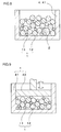
FIG. 8 is a schematic diagram illustrating a pressurizing step for the magnetic powder and a lubricant in the first embodiment; -
FIG. 9 is a schematic diagram illustrating the pressurizing step for the magnetic powder and a lubricant in the first embodiment; -
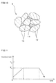
FIG. 10 is an enlarged view schematically depicting a configuration of the primary molding in the first embodiment; and -
FIG. 11 is a diagram illustrating changes in a heating temperature for a heat treatment step in the first embodiment. - A magnet manufacturing method according to the invention will be described as an embodiment with reference to
FIGS. 1 to 11 .FIG. 1 is a diagram illustrating steps of the magnet manufacturing method of a first embodiment. - As illustrated in step S1 in
FIG. 1 ,magnetic powder 1 of a hard magnetic material as a raw material for a magnet is prepared. - As the
magnetic powder 1, a compound is used which includes one or more of an Fe-N-based compound and an R-Fe-N-based compound. A rare earth element represented by R is preferably an element that is known as a so-called rare earth element and that is other than Dy. In particular, light rare earth elements are preferable, and among the light rare earth elements, Sm is suitable. The light rare earth elements described herein refer to elements included in lanthanoids and each having a smaller atomic weight than Gd, that is, La, Ce, Pr, Nd, Pm, Sm, and Eu. A specific composition of themagnetic powder 1 is not limited as long as themagnetic powder 1 is an Fe-N-based compound or an R-Fe-N-based compound. Powder of Sm2Fe17N3 or Fe16N2 is suitably used. - The
magnetic powder 1 prepared exhibits two peaks (a plurality of peaks) as depicted inFIG. 2 when a particle size distribution is measured. A measurement method for the particle size distribution is not limited. Any measurement method (calculation method) may be used which allows particle size and frequency to be understood. - The particle size distribution of the
magnetic powder 1 in the present embodiment illustrated inFIG. 2 has two peaks at particle sizes of 0.75 µm and 4 µm. A manufacturing method for themagnetic powder 1 in the present embodiment is not limited as long as themagnetic powder 1 has the particle size distribution depicted inFIG. 2 . For example, themagnetic powder 1 is obtained by mixingfine powder 11 that exhibits a particle size distribution depicted inFIG. 3 and that has an average particle size (D50) of 0.75 µm withcoarse powder 12 that exhibits a particle size distribution depicted inFIG. 4 and that has an average particle size (D50) of 4 µm. As depicted inFIG. 3 and FIG. 4 , thefine powder 11 and thecoarse powder 12 each have sharp peaks in the particle size distribution. The particle size distribution peaks of thefine powder 11 and thecoarse powder 12 do not substantially overlap. - When the
magnetic powder 1 in the present embodiment is mixed powder of thefine powder 11 and thecoarse powder 12, the ratio of the particle size offine powder 11 to the particle size of thecoarse powder 12 preferably falls within a range from 1:4 to 1:7. When the ratio of the particle sizes is within this range, particles of thefine powder 11 are densely placed in gaps between particles of thecoarse powder 12. When the ratio of the particle sizes is lower than 1:4, each of the particles of thefine powder 11 is excessively small compared to the corresponding gap between the particles of thecoarse powder 12. Thus, gaps remain between the particles of thecoarse powder 12. When the ratio of the particle sizes is higher than 1:7, each of the particles of thefine powder 11 is larger than the corresponding gap between the particles of thecoarse powder 12. Thefine powder 11 hinders the particles of thecoarse powder 12 from being proximate to one another. In other words, the gaps between the particles of thecoarse powder 12 are enlarged. - When the
magnetic powder 1 in the present embodiment is mixed powder of thefine powder 11 and thecoarse powder 12, the volume ratio of thefine powder 11 to thecoarse powder 12 preferably falls within a range from 10:90 to 40:60. A volume ratio within this range allows the particles of thefine powder 11 to be densely placed in the gaps between the particles of thecoarse powder 12. A volume ratio of less than 10:90 leads to few particles of thefine powder 11 with respect to the gaps between the particles of thecoarse powder 12. Thus, gaps remain between the particles of thecoarse powder 12. A volume ratio of more than 40:60 leads to many particles of thefine powder 11 with respect to the gaps between the particles of thecoarse powder 12. Thus, thefine powder 11 is placed between the particles of thecoarse powder 12. As a result, the particles of thefine powder 11 hinder the particles of thecoarse powder 12 from being proximate to one another. In other words, the gaps between the particles of thecoarse powder 12 are enlarged. -
FIG. 5 illustrates a relationship between the mixture ratio (volume ratio) of thefine powder 11 to thecoarse powder 12 in themagnetic powder 1 inFIG. 2 and the density of a primary molding obtained in a pressurizing step described below (step S4) in the present embodiment. -
FIG. 5 indicates that a dense primary molding is obtained by setting the volume ratio of thefine powder 11 to thecoarse powder 12 to 10:90 to 40:60. As depicted inFIG. 5 , the volume ratio of thefine powder 11 to the coarse powder is more preferably 10:90 to 20:80. The magnetic powder in the present embodiment is obtained by mixing thefine powder 11 and thecoarse powder 12 such that the volume ratio of thefine powder 11 to thecoarse powder 12 is 15:85. This ratio is most preferable. - The
magnetic powder 1 in the present embodiment is formed by mixing a plurality of types of powder with the same compositions (fine powder 11 and coarse powder 12) but may be formed by mixing a plurality of types of powder with different compositions. - The
magnetic powder 1 prepared in the present embodiment preferably contains an even mixture of thefine powder 11 and thecoarse powder 12. That is, themagnetic powder 1 is preferably obtained by mixing and stirring thefine powder 11 and thecoarse powder 12. The mixture of thefine powder 11 and thecoarse powder 12 may be performed in step S3 described below in conjunction with mixing and stirring of a lubricant and themagnetic powder 1. - In the
magnetic powder 1 in the present embodiment, the particle size (average particle size: D50) of the particles of thecoarse powder 12 is preferably approximately 2 µm to 5 µm and more preferably approximately 3 µm to 4 µm. The particle size (average particle size: D50) of the particles of thefine powder 11 is preferably approximately 0.29 µm to 1.25 µm and more preferably approximately 0.43 µm to 1.00 µm. - As illustrated in step S2 in
FIG. 1 , themagnetic powder 1 prepared in step S1 and a lubricant 2 (solid lubricant powder) that is powdery at normal temperature are prepared. - Metal soap powder is used as the
lubricant 2. As thelubricant 2, powder of stearic acid-based metal such as zinc stearate is used. The particle size of thelubricant 2 is not limited but may be approximately 10 µm. In other words, thelubricant 2 has a larger average particle size than thecoarse powder 12 in themagnetic powder 1. Thelubricant 2 has a smaller specific gravity than themagnetic powder 1. Setting a somewhat large initial size for thelubricant 2 enables each particle of thelubricant 2 to have a large mass. This prevents thelubricant 2 from being stirred up in step S3 described below when thelubricant 2 is mixed with themagnetic powder 1. - As illustrated in step S3 in
FIG. 1 , themagnetic powder 1 and thelubricant 2 prepared in the step S2 are mixed together while being ground. - A mixture ratio between the
magnetic powder 1 and thelubricant 2 can be optionally set. The preferable mixture ratio between themagnetic powder 1 and thelubricant 2 is such that, in volume percentage, the magnetic powder is 80 to 90 vol%, whereas thelubricant 2 is 5 to 15 vol%. Besides themagnetic powder 1 and thelubricant 2, an additive may be added. Examples of the additive include organic solvents that disappear as a result of subsequent heating. - Any method may be used to mix the
magnetic powder 1 and thelubricant 2 together as long as the method allows themagnetic powder 1 and thelubricant 2 to be mixed together while being ground. For example, in amixture container 3, the magnetic powder 1 (fine powder 11 and coarse powder 12) and thelubricant 2 are mixed together while being ground as depicted in a schematic diagram inFIG. 6 . Mixing and simultaneously grinding themagnetic powder 1 and thelubricant 2 fractionizes thelubricant 2, which has a low binding strength, to reduce the general particle size of thelubricant 2, as depicted in a schematic diagram inFIG. 7 . Thus, particles of thelubricant 2 present at the end of the mixing step have different particle sizes. - During the mixture of the
magnetic powder 1 and thelubricant 2, grinding is performed at a pressure at which themagnetic powder 1 is prevented from being destroyed. - At the end of the mixing step, the mixed powder of the
magnetic powder 1 and thelubricant 2 can contain reduced massive portions formed only of themagnetic powder 1 and have a reduced particle size of thelubricant 2. In other words,fine particles 2 and 2' of the lubricant resulting from crushing can be present at positions proximate to each particle of themagnetic powder 1. - Subsequently, as illustrated in step S4 in
FIG. 1 , the mixed powder of themagnetic powder 1 and thelubricant 2 is pressurized to form a primary molding 5 (FIGS. 8 and 9 ). - In the pressurizing step, as depicted in a schematic diagram in
FIG. 8 , the mixed powder of themagnetic powder 1 and thelubricant 2 is fed into a cavity in a pressurizing mold 4 (pressurizing lower mold 41 (mold)). - As depicted in a schematic diagram in
FIG. 9 , a pressurizing upper mold 42 (mold) is assembled into the pressurizinglower mold 41 and moved in a direction in which the pressurizingupper mold 42 approaches the pressurizinglower mold 41. Thus, the mixed powder is molded under pressure using the pressurizing mold 4 (41 and 42). At this time, a pressure applied by the pressurizing mold 4 (41 and 42) is a pressure equal to or lower than a fracture pressure at which themagnetic powder 1 in the mixed powder of themagnetic powder 1 and thelubricant 2 is destroyed. In the present embodiment, the applied pressure is equal to or lower than 1GPa. - Pressurization with the pressurizing mold 4 (41 and 42) is performed a plurality of times. In other words, after a pressure is applied to the pressurizing
upper mold 42, the pressure applied to the pressurizingupper mold 42 is weakened, and then, a pressure is applied to the pressurizingupper mold 42 again. Then, this operation is repeated. To weaken the pressure applied to the pressurizingupper mold 42, the pressurizingupper mold 42 may be moved upward or only the applied pressure may be reduced without upward movement of the pressurizingupper mold 42. - Pressurization with the pressurizing mold 4 (41 and 42) is performed a plurality of times, and an upper limit on the number of pressurizations may be the number of pressurizations resulting in saturation of the effect of an increase in the density of the primary molding. For example, the pressurization may be performed twice to thirty times.
- In the pressurizing step, the pressurizing mold 4 (41 and 42) is heated at an outer side surface thereof using a heater (not depicted in the drawings) to heat the mixed powder of the
magnetic powder 1 and thelubricant 2. A heating temperature T1 for the mixed powder of themagnetic powder 1 and thelubricant 2 is lower than a decomposition temperature of themagnetic powder 1 and equal to or higher than a melting point T3 of the lubricant 2 (T3 ≤ T1 < T2). Therefore, themagnetic powder 1 is not decomposed even on heating. Thelubricant 2, which is solid (powdery) at normal temperature, becomes a liquid during the pressurizing step because thelubricant 2 is heated at the melting point thereof or higher. - In this manner, while the
magnetic powder 1, contained in the mixed powder of themagnetic powder 1 and thelubricant 2, is being pressurized, thelubricant 2 becomes a liquid instead of a solid and has a viscosity corresponding to the temperature. The viscosity of thelubricant 2 decreases with an increase in the heating temperature T1. Theliquid lubricant 2 adheres to the entire surface of each of the particles of themagnetic powder 1 without being segregated. - As depicted in an enlarged view in
FIG. 10 , repeated pressurizations allow an increasing number of particles of thefine powder 11 to be placed between the particles of thecoarse powder 12. Thus, aprimary molding 5 is formed with reduced gaps between the particles of themagnetic powder 1. This is because a plurality of pressurizations allows rearrangement of the particles of themagnetic powder 1 arranged as a result of the last pressurization. - In the pressurizing
mold 4, theliquid lubricant 2 is interposed between the adjacent particles of themagnetic powder 1 to allow the particles of themagnetic powder 1 to move smoothly. The gaps between the particles of themagnetic powder 1 in theprimary molding 5 are reduced by synergetic action of rearrangement of the particles of themagnetic powder 1 and sliding of the particles of themagnetic powder 1 due to thelubricant 2. - As illustrated in step S5 in
FIG. 1 , theprimary molding 5 is heated in an oxidizing atmosphere to form a secondary molding (heat treatment step). - Heating the
primary molding 5 in the oxidizing atmosphere causes exposed surfaces of the particles of themagnetic powder 1 to react with oxygen to generate an oxide film on the surface of each of the particles of themagnetic powder 1. The oxide film joins the surfaces of the adjacent particles of themagnetic powder 1. The oxide film is formed on a portion of each particle of themagnetic powder 1, which is exposed to the gap, while a base material with no oxide film formed thereon constitutes a portion of each particle of themagnetic powder 1, which is not exposed to the gap (the interface at which the particle of themagnetic powder 1 is compressed against the adjacent particle of the magnetic powder 1). Therefore, the oxide film is not formed all over the surface of each particle of themagnetic powder 1. - The secondary molding thus formed has a sufficient strength. This enables an increase in a flexural strength of the secondary molding. Moreover, in the pressurizing step, areas of the
primary molding 5 where nomagnetic powder 1 is present are reduced, enabling an increase in residual magnetic flux density of the secondary molding resulting from the heat treatment step. The secondary molding has a density of approximately 5 to 6 g/cm3. - The heat treatment step is executed with the
primary molding 5 placed in a microwave heating furnace, an electric furnace, a plasma heating furnace, a high-frequency quenching furnace, a heating furnace with an infrared heater, or the like. The heating during the heat treatment step is not limited but may be performed so as to go through temperature changes depicted inFIG. 11 . - As depicted in
FIG. 11 , a heating temperature T4 is set lower than the decomposition temperature T2 of themagnetic powder 1. For example, when Sm2Fe17N3 or Fe16N2 is used as themagnetic powder 1, the heating temperature T4 is set lower than 500°C because the decomposition temperature T2 of Sim2Fe17N3 or Fe16N2 is approximately 500°C. For example, the heating temperature T4 in the heat treatment step is approximately 200 to 300°C. - An oxygen concentration and an atmospheric pressure in the oxidizing atmosphere may be set to any values as long as the oxygen concentration and the atmospheric pressure allow the
magnetic powder 1 to be oxidized. An oxygen concentration and an atmospheric pressure equal or close to the oxygen concentration and the atmospheric pressure in the air are sufficient for this purpose. Therefore, special management of the oxygen concentration and the atmospheric pressure is not needed. The heating may be performed in the aerial atmosphere. Setting the heating temperature T4 at approximately 200 to 300°C allows an oxide film to be formed regardless of whether the magnetic powder is Sm2Fe17N3 or Fe16N2. - As illustrated in step S6 in
FIG. 1 , a treatment is executed in which the surface of the secondary molding formed in the heat treatment step is covered with a coating film, to form a tertiary molding. - Examples of the coating film for the tertiary molding include a plating film formed by electroplating of Cr, Zn, Ni, Ag, Cu, or the like, a plating film formed by electroless plating, a resin film formed by resin coating, a glass film formed by glass coating, and a film formed of Ti, diamond-like carbon (DLC), or the like. Examples of the electroless plating include electroless plating using Ni, Au, Ag, Cu, Sn, Co, or an alloy or a mixture thereof. Examples of the resin coating include coating with a silicone resin, a fluorine resin, a urethane resin, or the like.
- The coating film formed on the tertiary molding functions like an egg shell. The tertiary molding can have an increased flexural strength as a result of a joining force exerted by the oxide film and the coating film. In particular, the electroless plating enables surface hardness and adhesion to be enhanced and allows the joining force of the
magnetic powder 1 to be made stronger. Furthermore, for example, electroless nickel-phosphorous plating offers high corrosion resistance. - As described above, the oxide film joins the particles of the
magnetic powder 1 together not only on the surface of the secondary molding but also inside the secondary molding. The joining force of the oxide film regulates free movement of the particles of themagnetic powder 1 inside the tertiary molding. This suppresses inversion of magnetic poles resulting from rotation of themagnetic powder 1. A high residual magnetic flux density can be achieved. - When the electroplating is applied in the coating step, the unplated secondary molding acts as an electrode. Thus, the secondary molding needs to have a high joining strength. However, when the electroless plating, the resin coating, or the glass coating is applied in the coating step, the joining strength of the secondary molding need not be so high as the joining strength needed for the secondary molding when the electroplating is applied. The joining force resulting from the oxide film is sufficient. Therefore, the coating step as described above allows the coating film to be reliably formed on the surface of the secondary molding.
- When the electroless plating is applied in the coating step, the secondary molding is immersed in a plating solution. At this time, the plating solution acts to enter the inside of the secondary molding. However, the oxide film formed on the secondary molding effectively suppresses the entry of the plating solution. This is expected to inhibit possible corrosion of the secondary molding or the like resulting from the entry of the plating solution into the inside of the secondary molding.
- In the manufacturing method of the present embodiment, a compound that includes one or more of an Fe-N-based compound and an R-Fe-N-based compound (R: rare earth element) is used as the
magnetic powder 1 of the hard magnetic material. Thus, a magnet can be inexpensively manufactured. - Furthermore, the manufacturing method in the present embodiment allows avoidance of the use of dysprosium (Dy) as R. Therefore, a magnet can be inexpensively manufactured.
- In the step of preparing the magnetic powder of the hard magnetic material (step 1) in the manufacturing method in the present embodiment, the magnetic powder prepared exhibits at least two peaks when the particle size distribution is measured. In the subsequent pressurizing step of obtaining the primary molding 5 (step S4), the
magnetic powder 1 is pressurized at the pressure equal to or lower than the fracture pressure so that the particles of themagnetic powder 1 that have small particle sizes (fine powder 11) are fitted between the gaps defined between the particles of themagnetic powder 1 that have large particle sizes (coarse powder 12). Thus, the denseprimary molding 5 with reduced gaps is obtained. Theprimary molding 5 is heated (subjected to heat treatment) to join the surfaces of particles of themagnetic powder 1 together to form a secondary molding. The secondary molding is configured such that the magnetic powder particles are joined together in the denseprimary molding 5 with the filled gaps. - As described above, the manufacturing method according to the present embodiment allows manufacture of a dense magnet with filled gaps.
- The manufacturing method according to the present embodiment allows a magnet with a high residual magnetic flux density to be obtained without the use of dysprosium (Dy) or a bond. In the manufacturing method according to the present embodiment, since a magnet with a high residual magnetic flux density can be obtained, a magnet can be acquired which has high magnetic characteristics in spite of its complicated shape.
- In the manufacturing method according to the present embodiment, the
magnetic powder 1 is prepared which is a mixture of two or more types of magnetic powder (fine powder 11 and coarse powder 12) with different average particle sizes (D50). Thus, themagnetic powder 1 is easily obtained which exhibits at least two peaks when the particle size distribution is measured. - In the manufacturing method according to the present embodiment, the pressurization is performed a plurality of times in the pressurizing step (step S4). Performing the pressurization twice or more causes the
fine powder 11 to move to the gaps between the particles of thecoarse powder 12, leading to the denseprimary molding 5 with filled gaps. - In the manufacturing method according to the present embodiment, the
solid lubricant powder 2 is mixed with themagnetic powder 1. Consequently, the pressurization in the pressurizing step (step S4) facilitates movement of thefine powder 11 to the gaps between the particles of thecoarse powder 12. That is, the denseprimary molding 5 with filled gaps is obtained. - In heat treatment step (step S5) of heating the
primary molding 5 in the manufacturing method according to the present embodiment, theprimary molding 5 is heated at a temperature equal to or higher than the melting point T3 of thelubricant 2. Consequently, thelubricant 2 is placed on the surface of each of the particles of themagnetic powder 1 forming theprimary molding 5. - In the first embodiment described above, as the magnetic powder of the hard magnetic material serving as the raw material of the magnet, magnetic powder is used which exhibits two peaks when the particle size distribution is measured. However, according to a second embodiment, magnetic powder with three or more peaks may be used.
- Even in this case, magnetic powder can be prepared by mixing a number of types of powder with different average particle sizes together. When the magnetic powder is formed by mixing fine powder, medium powder, and coarse powder together, the magnetic powder exhibits three peaks when the particle size distribution is measured.
- Preferably, in the magnetic powder with three peaks, the ratio of the particle size (average particle size: D50) of the
fine powder 11 to the particle size (average particle size: D50) of the medium powder falls within a range from 1:5 to 1:7, and the ratio of the particle size (average particle size: D50) of the medium powder to the particle size (average particle size: D50) of thecoarse powder 12 falls within a range from 1:5 to 1:7. - Preferably, in the magnetic powder with three peaks, the volume ratio of the fine powder to the medium powder falls within a range from 10:90 to 40:60 and the volume ratio of the medium powder to the coarse powder falls within a range from 10:90 to 40:60.
- The present embodiment is configured similarly to the first embodiment except that the magnetic powder is formed by mixing the fine powder, the medium powder, and the coarse powder, and exerts effects similar to the effects of the first embodiment.
- In the present embodiment, the medium powder is placed in the gaps between the particles of the
coarse powder 12, and thefine powder 11 is placed in the gaps between the particles of the medium powder. That is, a dense primary molding with more appropriately filled gaps is obtained. - In the pressurizing step in the above-described embodiments, the mixed powder of the
magnetic powder 1 and thelubricant 2 is heated by heating the pressurizingmold 4. However, the invention is not limited to these embodiments. The mixed powder of themagnetic powder 1 and thelubricant 2 may be heated to the heating temperature T1 immediately before being placed in the pressurizingmold 4. - In the above-described embodiments, the
lubricant 2 used is solid (powdery) at normal temperature. However, a lubricant that is liquid at normal temperature may be used. Even in this case, the liquid lubricant and themagnetic powder 1 may be mixed together in the mixing step. Moreover, the mixed powder is heated in the pressurizing step to reduce the viscosity of the lubricant. Thus, the lubricant spreads all over the surface of themagnetic powder 1. This allows the particles of themagnetic powder 1 to move smoothly, resulting in an increased density of theprimary molding 5.
Claims (6)
- A magnet manufacturing method comprising:preparing magnetic powder of a hard magnetic material, which includes one or more of an Fe-N-based compound and an R-Fe-N-based compound;pressurizing and molding the magnetic powder at a pressure equal to or lower than a fracture pressure at which particles of the magnetic powder are destroyed in order to obtain a primary molding; andheating the primary molding at a temperature lower than a decomposition temperature of the magnetic powder, whereinthe magnetic powder has at least two peaks in a particle size distribution.
- The magnet manufacturing method according to claim 1, wherein
the magnetic powder is a mixture of two or more types of magnetic powder with different average particle sizes. - The magnet manufacturing method according to claim 1 or 2, wherein
the pressurization is performed a plurality of times. - The magnet manufacturing method according to any one of claims 1 to 3, wherein solid lubricant powder is mixed with the magnetic powder.
- The magnet manufacturing method according to claim 4, wherein
in the heating of the primary molding, the primary molding is heated at a temperature equal to or higher than a melting point of the solid lubricant. - A magnet manufactured by the magnet manufacturing method according to any one of claims 1 to 5.
Applications Claiming Priority (1)
| Application Number | Priority Date | Filing Date | Title |
|---|---|---|---|
| JP2015084009A JP2016207710A (en) | 2015-04-16 | 2015-04-16 | Manufacturing method of magnet and magnet |
Publications (1)
| Publication Number | Publication Date |
|---|---|
| EP3086333A1 true EP3086333A1 (en) | 2016-10-26 |
Family
ID=55752218
Family Applications (1)
| Application Number | Title | Priority Date | Filing Date |
|---|---|---|---|
| EP16165125.2A Withdrawn EP3086333A1 (en) | 2015-04-16 | 2016-04-13 | Magnet manufacturing method and magnet |
Country Status (4)
| Country | Link |
|---|---|
| US (1) | US20160303651A1 (en) |
| EP (1) | EP3086333A1 (en) |
| JP (1) | JP2016207710A (en) |
| CN (1) | CN106057458A (en) |
Families Citing this family (6)
| Publication number | Priority date | Publication date | Assignee | Title |
|---|---|---|---|---|
| JP6825373B2 (en) * | 2017-01-12 | 2021-02-03 | Tdk株式会社 | Soft magnetic materials, cores and inductors |
| JP6825372B2 (en) * | 2017-01-12 | 2021-02-03 | Tdk株式会社 | Soft magnetic materials, cores and inductors |
| JP6458853B1 (en) * | 2017-12-14 | 2019-01-30 | Tdk株式会社 | Powder magnetic core and inductor element |
| JP7028123B2 (en) * | 2018-09-21 | 2022-03-02 | トヨタ自動車株式会社 | Manufacturing method of rare earth magnets |
| WO2021157274A1 (en) | 2020-02-05 | 2021-08-12 | 富士フイルム株式会社 | Magnetic particle-containing composition, magnetic particle-containing film, and electronic component |
| JP7693583B2 (en) * | 2021-11-01 | 2025-06-17 | トヨタ自動車株式会社 | Rare earth magnet and its manufacturing method |
Citations (10)
| Publication number | Priority date | Publication date | Assignee | Title |
|---|---|---|---|---|
| JPS62206801A (en) | 1986-03-07 | 1987-09-11 | Tohoku Metal Ind Ltd | Manufacture of rare earth magnet |
| JPH0855712A (en) * | 1994-05-25 | 1996-02-27 | Asahi Chem Ind Co Ltd | Magnetic material and its manufacturing method |
| JP2004072005A (en) * | 2002-08-09 | 2004-03-04 | Matsushita Electric Ind Co Ltd | Manufacturing method of resin-bonded magnet and magnet motor |
| JP2005223263A (en) | 2004-02-09 | 2005-08-18 | Sumitomo Metal Mining Co Ltd | Rare earth permanent magnet manufacturing method and obtained rare earth permanent magnet |
| JP2007039794A (en) | 2005-06-30 | 2007-02-15 | Toyota Motor Corp | Method for producing hard magnetic alloy nanoparticles and method for producing nanocomposite magnets |
| JP2012069962A (en) | 2011-10-19 | 2012-04-05 | Asahi Kasei Chemicals Corp | Solid material for magnets |
| WO2013090895A1 (en) * | 2011-12-15 | 2013-06-20 | Case Western Reserve University | Transformation enabled nitride magnets absent rare earths and a process of making the same |
| US20130266474A1 (en) * | 2011-08-22 | 2013-10-10 | Sumitomo Electric Industries, Ltd. | Method for producing magnetic green compacts, magnetic green compact, and sintered body |
| EP2704159A1 (en) * | 2011-04-27 | 2014-03-05 | Toda Kogyo Corporation | Process for producing ferromagnetic particulate powder, and anisotropic magnet, bonded magnet, and compacted magnet |
| JP2015008200A (en) | 2013-06-25 | 2015-01-15 | 株式会社ジェイテクト | Method of manufacturing magnet and magnet |
-
2015
- 2015-04-16 JP JP2015084009A patent/JP2016207710A/en active Pending
-
2016
- 2016-04-08 US US15/094,706 patent/US20160303651A1/en not_active Abandoned
- 2016-04-13 EP EP16165125.2A patent/EP3086333A1/en not_active Withdrawn
- 2016-04-14 CN CN201610230751.1A patent/CN106057458A/en active Pending
Patent Citations (10)
| Publication number | Priority date | Publication date | Assignee | Title |
|---|---|---|---|---|
| JPS62206801A (en) | 1986-03-07 | 1987-09-11 | Tohoku Metal Ind Ltd | Manufacture of rare earth magnet |
| JPH0855712A (en) * | 1994-05-25 | 1996-02-27 | Asahi Chem Ind Co Ltd | Magnetic material and its manufacturing method |
| JP2004072005A (en) * | 2002-08-09 | 2004-03-04 | Matsushita Electric Ind Co Ltd | Manufacturing method of resin-bonded magnet and magnet motor |
| JP2005223263A (en) | 2004-02-09 | 2005-08-18 | Sumitomo Metal Mining Co Ltd | Rare earth permanent magnet manufacturing method and obtained rare earth permanent magnet |
| JP2007039794A (en) | 2005-06-30 | 2007-02-15 | Toyota Motor Corp | Method for producing hard magnetic alloy nanoparticles and method for producing nanocomposite magnets |
| EP2704159A1 (en) * | 2011-04-27 | 2014-03-05 | Toda Kogyo Corporation | Process for producing ferromagnetic particulate powder, and anisotropic magnet, bonded magnet, and compacted magnet |
| US20130266474A1 (en) * | 2011-08-22 | 2013-10-10 | Sumitomo Electric Industries, Ltd. | Method for producing magnetic green compacts, magnetic green compact, and sintered body |
| JP2012069962A (en) | 2011-10-19 | 2012-04-05 | Asahi Kasei Chemicals Corp | Solid material for magnets |
| WO2013090895A1 (en) * | 2011-12-15 | 2013-06-20 | Case Western Reserve University | Transformation enabled nitride magnets absent rare earths and a process of making the same |
| JP2015008200A (en) | 2013-06-25 | 2015-01-15 | 株式会社ジェイテクト | Method of manufacturing magnet and magnet |
Also Published As
| Publication number | Publication date |
|---|---|
| US20160303651A1 (en) | 2016-10-20 |
| JP2016207710A (en) | 2016-12-08 |
| CN106057458A (en) | 2016-10-26 |
Similar Documents
| Publication | Publication Date | Title |
|---|---|---|
| US20160303651A1 (en) | Magnet Manufacturing Method And Magnet | |
| KR102093491B1 (en) | Manufacturing method of sintered magnet and sintered magnet | |
| JP2009289994A (en) | Process for producing magnet | |
| EP2822003A1 (en) | Magnet manufacturing method and magnet | |
| JP7183890B2 (en) | Method for manufacturing rare earth magnet | |
| KR101918975B1 (en) | MAGNET of Nd-Fe-B SYSTEM AND THE MANUFACTURING METHOD THEREOF | |
| TW201606815A (en) | Soft magnetic metal powder and soft magnetic metal powder core using the same | |
| EP2869311A1 (en) | Method of manufacturing fully dense Nd-Fe-B magnets with enhanced coercivity and gradient microstructure | |
| JP2018018859A (en) | R-T-B sintered magnet | |
| EP0249973A1 (en) | Permanent magnetic material and method for producing the same | |
| EP3401933A1 (en) | Mn-Bi-BASED MAGNETIC POWDER, METHOD FOR PRODUCING SAME, COMPOUND FOR BOND MAGNET, BOND MAGNET, Mn-Bi-BASED METAL MAGNET AND METHOD FOR PRODUCING SAME | |
| JP2014203922A (en) | Production method of magnet and magnet | |
| JP2015008200A (en) | Method of manufacturing magnet and magnet | |
| EP3089174A1 (en) | Magnet manufacturing method and magnet | |
| KR101744403B1 (en) | Manufacturing method of rare-earth magnet | |
| JP6769479B2 (en) | Rare earth permanent magnet | |
| EP3113195A1 (en) | Manufacturing method for magnet and magnet | |
| EP1662518A1 (en) | Soft magnetic material and method for producing same | |
| EP3086332A1 (en) | Magnet manufacturing method and magnet | |
| JP2017022192A (en) | Manufacturing method for magnet and magnet | |
| JP2015008201A (en) | Magnet manufacturing method and magnet | |
| CN105103249A (en) | Sintered magnet manufacturing method | |
| JP6620570B2 (en) | Method for producing metal bonded magnet | |
| EP3113198A1 (en) | Manufacturing method for magnet and magnet | |
| KR102658773B1 (en) | Manufacturing method of sintered magnet |
Legal Events
| Date | Code | Title | Description |
|---|---|---|---|
| PUAI | Public reference made under article 153(3) epc to a published international application that has entered the european phase |
Free format text: ORIGINAL CODE: 0009012 |
|
| AK | Designated contracting states |
Kind code of ref document: A1 Designated state(s): AL AT BE BG CH CY CZ DE DK EE ES FI FR GB GR HR HU IE IS IT LI LT LU LV MC MK MT NL NO PL PT RO RS SE SI SK SM TR |
|
| AX | Request for extension of the european patent |
Extension state: BA ME |
|
| STAA | Information on the status of an ep patent application or granted ep patent |
Free format text: STATUS: THE APPLICATION IS DEEMED TO BE WITHDRAWN |
|
| 18D | Application deemed to be withdrawn |
Effective date: 20170427 |