EP3086149B1 - Koaxialer fotodetektor - Google Patents
Koaxialer fotodetektor Download PDFInfo
- Publication number
- EP3086149B1 EP3086149B1 EP16166133.5A EP16166133A EP3086149B1 EP 3086149 B1 EP3086149 B1 EP 3086149B1 EP 16166133 A EP16166133 A EP 16166133A EP 3086149 B1 EP3086149 B1 EP 3086149B1
- Authority
- EP
- European Patent Office
- Prior art keywords
- sleeve
- optical
- filtering
- filtering assembly
- port adapter
- Prior art date
- Legal status (The legal status is an assumption and is not a legal conclusion. Google has not performed a legal analysis and makes no representation as to the accuracy of the status listed.)
- Active
Links
Images

Classifications
-
- G—PHYSICS
- G02—OPTICS
- G02B—OPTICAL ELEMENTS, SYSTEMS OR APPARATUS
- G02B6/00—Light guides; Structural details of arrangements comprising light guides and other optical elements, e.g. couplings
- G02B6/24—Coupling light guides
- G02B6/42—Coupling light guides with opto-electronic elements
- G02B6/4201—Packages, e.g. shape, construction, internal or external details
- G02B6/4256—Details of housings
- G02B6/4262—Details of housings characterised by the shape of the housing
- G02B6/4263—Details of housings characterised by the shape of the housing of the transisitor outline [TO] can type
-
- G—PHYSICS
- G02—OPTICS
- G02B—OPTICAL ELEMENTS, SYSTEMS OR APPARATUS
- G02B6/00—Light guides; Structural details of arrangements comprising light guides and other optical elements, e.g. couplings
- G02B6/24—Coupling light guides
- G02B6/42—Coupling light guides with opto-electronic elements
- G02B6/4292—Coupling light guides with opto-electronic elements the light guide being disconnectable from the opto-electronic element, e.g. mutually self aligning arrangements
-
- G—PHYSICS
- G02—OPTICS
- G02B—OPTICAL ELEMENTS, SYSTEMS OR APPARATUS
- G02B6/00—Light guides; Structural details of arrangements comprising light guides and other optical elements, e.g. couplings
- G02B6/24—Coupling light guides
- G02B6/36—Mechanical coupling means
- G02B6/38—Mechanical coupling means having fibre to fibre mating means
- G02B6/3807—Dismountable connectors, i.e. comprising plugs
- G02B6/381—Dismountable connectors, i.e. comprising plugs of the ferrule type, e.g. fibre ends embedded in ferrules, connecting a pair of fibres
- G02B6/3825—Dismountable connectors, i.e. comprising plugs of the ferrule type, e.g. fibre ends embedded in ferrules, connecting a pair of fibres with an intermediate part, e.g. adapter, receptacle, linking two plugs
Definitions
- the present invention relates to photodetectors, and in particular, to a coaxial photodetector.
- a coaxial photodetector is configured to covert an optical signal into an electrical signal.
- An existing coaxial photodetector does not have a function of receiving a particular wavelength.
- a filtering apparatus needs to be added on a front end of an optical path of the coaxial photodetector to select a light beam having a particular wavelength, and then the coaxial photodetector receives the light beam having the particular wavelength.
- FIG. 1 is a schematic structure diagram of a common optical path in the prior art. As shown in FIG.
- an input optical path of a filtering apparatus 101 is connected to an optical fiber 11
- an output optical path of the filtering apparatus 101 is connected to a coaxial photodetector 102 by using the optical fiber 11.
- An optical signal transmitted in the optical fiber 11 is output to the filtering apparatus 101, and after filtration by the filtering apparatus 101, a light beam having a particular wavelength in the optical signal is output and is transmitted to the coaxial photodetector 102 by the optical fiber 11, and is converted into an electrical signal by the coaxial photodetector 102.
- an extra filtering apparatus needs to be added, which does not facilitate layout miniaturization of a module in which the coaxial photodetector is located, and the filtering apparatus and the coaxial photodetector are mutually connected by using an optical fiber, and a relatively large extra loss is caused to an optical signal after multiple times of conversion from free space to the optical fiber.
- US 2004/0223761 A1 discloses a bidirectional transmitting and receiving device having a waveguide for sending light, a receiving/transmitting area (1/2) for receiving and processing light and a diffractive lens (3) operating as a filtering element between the waveguide area and the receiving transmitting area (1/2)
- US 2005/0169586 A1 discloses a bidirectional optical transceiver, wherein a filtering element is disposed between a supporting holder for retaining an optical fiber and a TO-CAN.
- US 2005/0175299 A1 discloses an optical sub-assembly package for use in receiver optical sub-assemblies or transmitter optical sub-assemblies in which the electrical connections between the transducer chip, e.g. photo-detector or light source, and the device printed circuit board is made by a single flexible circuit conductor extending through the wall of the package.
- the package is comprised of a housing and a stiffening plate, which encloses and end of the housing and forms a mechanical support for an end of the flexible circuit conductor.
- US 2013/0064498 A1 discloses an optical sub-assembly module having a fiber for delivering optical signals, a transmitter, a receiver and an intermediate optical mechanism optically coupled to the fiber, the transmitter and the receiver.
- the intermediate optical mechanism includes a fiber-end interface for receiving the optical signals from the fiber or outputting the optical signals generated by the transmitter to the fiber; a transmission-end interface for receiving the optical signals from the transmitter; a reception-end interface or outputting the optical signals from the fiber to the receiver; and a filtering interface in the inside of the intermediate optical mechanism for realizing the optical signal delivery from the transmitter to the fiber and from the fiber to the receiver.
- the fiber-end interface, the transmission-end interface and the reception-end interface are parts of an integral whole while the filtering interface is a part of the same integral whole or an independent filter.
- Embodiments of the present invention provide a coaxial photodetector, which can filter a light beam, so that a photodiode in the coaxial photodetector has a function of receiving a light beam having a particular wavelength, and an optical loss caused to an optical signal converted between free space and an optical fiber is reduced.
- a coaxial photodetector including:
- a central axis of the filtering assembly is a preset distance deviated from a light output port of the optical port adapter that outputs a light beam to the filtering assembly, and a plane of incidence of the filtering piece is perpendicular to the central axis of the filtering assembly.
- a filtering assembly having a filtering function is integrated into a coaxial photodetector, and an overall size of the coaxial photodetector into which the filtering assembly is integrated is not increased significantly as compared with an overall size of the original coaxial photodetector, so that the coaxial photodetector in the present invention filters a light beam while keeping miniature, and a photodiode in the coaxial photodetector has a function of receiving a light beam having a particular wavelength.
- a quantity of times of conversion of an optical signal between free space and an optical fiber is reduced, thereby reducing an optical loss caused to the optical signal converted between the free space and the optical fiber.
- Embodiments of the present invention provide a coaxial photodetector, which can filter a light beam, so that a photodiode in the coaxial photodetector has a function of receiving a light beam having a particular wavelength, and an optical loss caused to an optical signal converted between free space and an optical fiber is reduced.
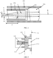
- FIG. 2 is a structural framework diagram of an embodiment of a coaxial photodetector according to the present invention.
- the coaxial photodetector includes an optical port adapter 21, a filtering assembly 22, a connecting tube body 23, and a transistor-outline can (TO-CAN) 24.
- FIG. 3 is a structural diagram of the coaxial photodetector shown in FIG. 2 .
- the TO-CAN 24 includes a photodiode 241, configured to convert an input optical signal into an electrical signal.
- Two ends of the connecting tube body 23 are separately connected to the optical port adapter 21 and the TO-CAN 24, so that the optical port adapter 21 and the TO-CAN 24 are fastened to each other.
- the two ends of the connecting tube body 23 may be separately connected to the optical port adapter 21 and the TO-CAN 24 by means of adhesion or welding (for example, electric resistance welding), to ensure air-tightness of a hollow area inside the connecting tube body 23.
- adhesion or welding for example, electric resistance welding
- the filtering assembly 22 is further disposed between the optical port adapter 21 and the TO-CAN 24, and is configured to transmit light within a preset range in an input light beam and reflect other light in the input light beam except the light within the preset range.
- the optical port adapter 21 is configured to connect to an optical fiber, a light beam from the optical fiber is guided to the filtering assembly 22 by the optical port adapter 21, and a part of the light transmitted by the filtering assembly 22 is output to the photodiode 241.
- a filtering assembly having a filtering function is integrated into a coaxial photodetector, and an overall size of the coaxial photodetector into which the filtering assembly is integrated is not increased significantly as compared with an overall size of the original coaxial photodetector, so that the coaxial photodetector in the present invention implements a function of receiving a particular wavelength while keeping miniature.
- a quantity of times of conversion of an optical signal between free space and an optical fiber is reduced, thereby reducing an optical loss caused to the optical signal converted between the free space and the optical fiber.
- the filtering assembly 22 includes a collimation lens 221, a filtering piece 222 and a convergence lens 223 that are sequentially arranged along an optical path.
- the light beam from the optical fiber is guided by the optical port adapter 21 to the collimation lens 221 for collimation.
- the collimated light beam is input to the filtering piece 222, and the filtering piece 222 is configured to transmit light whose wavelength is within a preset range and reflect light whose wavelength is within another range except the preset range.
- the filtering piece 222 is a light filter, and certainly, the filtering piece 222 may also have another structural form, which is not limited herein.
- Light beams transmitted by the filtering piece 222 are converged to the photodiode 241 in the TO-CAN 24 by the convergence lens 223, and converted into an electrical signal by the photodiode 241.
- a coaxial photodetector has a relatively strict requirement on a wavelength range of a light beam that is input to a photodiode. Therefore, in the prior art, a common assembly method is to adjust a placement angle of the light filter to change the incidence angle of the input light beam of the light filter, so that a spectrum of a light beam transmitted by the light filter meets a requirement.
- a common assembly method is to adjust a placement angle of the light filter to change the incidence angle of the input light beam of the light filter, so that a spectrum of a light beam transmitted by the light filter meets a requirement.
- an offset is easily caused when the light filter is fastened by means of adhesion after the placement angle is adjusted, causing a difference between the spectrum of the light beam transmitted by the light filter and a target spectrum.
- a central axis of the filtering assembly 22 is a preset distance deviated from a light output port of the optical port adapter 21, and a plane of incidence of the filtering piece 222 is perpendicular to the central axis of the filtering assembly 22.
- an optical axis of the collimation lens and an optical axis of the convergence lens coincide
- the central axis of the filtering assembly 22 refers to the coincident optical axis of the collimation lens 221 and the convergence lens 223.
- the light output port of the optical port adapter 21 refers to a light output port of the optical port adapter 21 that is configured to output a light beam to the filtering assembly 22.
- FIG. 4 is a schematic diagram of an operating principle of a coaxial photodetector according to the present invention.
- a position of A in FIG. 4 is on a focal point on the side of a plane of incidence of the collimation lens 221, and a position of B is a position that is a preset distance d deviated from the position of A in a direction perpendicular to an optical axis L.
- the light output port of the optical port adapter 21 is at the position of A, divergent light beams output from the light output port of the optical port adapter 21 are collimated by the collimation lens 221 into a parallel light beam parallel to the optical axis L for output.
- the placement angle of the filtering piece does not need to be adjusted when the filtering piece is fastened, but the filtering assembly is moved to change a deviation distance between the central axis of the filtering assembly and the light output port of the optical port adapter, so as to adjust an incidence angle of a light beam that is input to the filtering piece, and therefore a position of the filtering assembly may be adjusted to a position at which a spectrum of a light beam transmitted by the filtering piece satisfies a target spectrum. Because it is not easy to cause a deviation when the filtering assembly is fastened at a position that is adjusted, the structure used in the present invention can improve a yield rate.
- the coaxial photodetector further includes a first sleeve 25.
- the first sleeve 25 is disposed in the connecting tube body 23, and one end of the first sleeve and the optical port adapter 21 are fastened to each other.
- the first sleeve 25 may be fastened to the optical port adapter 21 by means of adhesion or welding.
- the filtering assembly 22 is fastened in the first sleeve 25.
- the filtering assembly 22 may be adhered in the first sleeve 25 or inlaid in the first sleeve 25 by means of interference fit. In this way, in the process of assembling the coaxial photodetector, the filtering assembly may be moved by moving the first sleeve.
- the first sleeve in which the filtering assembly is fastened may be fastened to the optical port adapter, the connecting tube body may be fastened to the TO-CAN 24, and then the optical port adapter and the TO-CAN 24 are mutually connected.
- the structure of the coaxial photodetector in the present invention facilitates assembly of the coaxial photodetector, and reduces assembly costs.
- the filtering assembly 22 further includes a second sleeve 224 having a first end and a second end, and the first end of the second sleeve 224 and the optical port adapter 21 are fastened to each other.
- the second sleeve 224 is fastened in an end of the first sleeve 25 closed to the optical port adapter 21.
- the collimation lens 221 is fastened in the second sleeve 224, and the filtering piece 222 is fastened on an end face of the second end of the second sleeve 224.
- a plane on which the end face of the second end of the second sleeve 224 is located is perpendicular to the central axis of the filtering assembly 22, so that the filtering piece 222 fastened on the end face of the second end is perpendicular to the central axis of the filtering assembly 22.
- the collimation lens 221 may be fastened in the second sleeve 224 by means of interference fit in the second sleeve, and the filtering piece 222 may be adhered on the end face of the second end of the second sleeve.
- the collimation lens and the filtering piece do not need to be coupled and adjusted when the filtering assembly is assembled, thereby simplifying the process of assembling the coaxial photodetector, avoiding decrease in a yield rate of the coaxial photodetector caused by a disqualified placement angle of the light filterer, and facilitating batch production of the coaxial photodetector.
- the photodiode 241 in the TO-CAN 24 is possibly not on a focal point of the convergence lens 223, that is, a light spot formed on the photodiode 241 by light beams converged by the convergence lens 223 is not a convergent light spot.
- the connecting tube body 23 is adjustable in length. In this way, a distance between the convergence lens 223 and the photodiode 241 in the TO-CAN 24 may be adjusted by adjusting the length of the connecting tube body 23, so that the photodiode 241 is on the focal point of a convergence lens.
- the connecting tube body 23 may also be not adjustable in length.
- the connecting tube body 23 includes a regulating ring 231 and a connecting sleeve 232 that are connected end to end, an end of the regulating ring 231 far away from the connecting sleeve 232 is connected to the optical port adapter 21, an end of the connecting sleeve 232 far away from the regulating ring 231 is connected to the TO-CAN 24.
- the regulating ring 231 having different lengths may be conveniently selected for assembly with the connecting sleeve 232 according to different requirements, and the regulating ring functions to adjust a distance between the filtering assembly and the photodiode.
- the regulating ring 231 may be made of an insulation material, so that the regulating ring 231 also has a galvanic isolation function.
- the insulation material may be a ceramic material, which is not limited herein.
- a structure of a TO-CAN generally includes a tube base and a photodiode disposed on the tube base, the photodiode is sealed in space enclosed by a tube cap and the tube base, the tube cap is provided with a spherical transmissive window, and a light beam is input to the photodiode through the light transmissive window.
- the photodiode 241 is fastened on a side of the tube base facing the connecting tube body 23.
- a transmissive window 2421 on the tube cap 242 in the TO-CAN 24 is planar. In this way, the distance between the convergence lens 223 and the photodiode 241 may be reduced, thereby reducing the length of the coaxial photodetector, and facilitating miniaturization of the coaxial photodetector.
- an optical port adapter has multiple structural forms. A specific structure is described in the following with reference to FIG. 3 and FIG. 5.
- FIG. 5 is a schematic structural diagram of the optical port adapter in the coaxial photodetector shown in FIG. 3 .
- the optical port adapter 21 includes a base 211, a sleeve 212, and a ferrule 213 connected to the optical fiber.
- the base 211 may be made of a metal material, and has a first end face (which is represented by a dashed line L1 in the figure) and a second end face (which is represented by a dashed line L2 in the figure) that are opposite to each other.
- the sleeve 212 and the ferrule 213 may be made of a ceramic material.
- a through hole 2111 running through the first end face and the second end face is disposed on the base 211, and an opening aperture of the through hole 2111 on the first end face is smaller than an opening aperture of the through hole 2111 on the second end face, so that an annular step 2112 facing the second end face is formed on an inner wall of the through hole 2111.
- the filtering assembly 22 is inserted into the through hole 2111 from the side of the second end face of the base 211 and abuts against the annular step 2112.
- the sleeve 212 has an end fastened on the first end face of the base 211, and the ferrule 213 has one part embedded in the sleeve 212 and the other part embedded in the through hole 2111.
- an end of the ferrule 213 far away from the base 211 is connected to a fiber interface, where the fiber interface is connected to the optical fiber, so that the ferrule 213 can receive a light beam from the optical fiber, and guide the light beam to the filtering assembly 22 in the connecting tube body 23.
- the optical port adapter may further include other parts, and is not limited to the parts described above, which is not limited herein.
- the disclosed system, apparatus, and method may be implemented in other manners.
- the described apparatus embodiment is merely exemplary.
- the unit division is merely logical function division and may be other division in actual implementation.
- a plurality of units or components may be combined or integrated into another system, or some features may be ignored or not performed.
- the displayed or discussed mutual couplings or direct couplings or communication connections may be implemented through some interfaces.
- the indirect couplings or communication connections between the apparatuses or units may be implemented in electronic, mechanical, or other forms.
- the units described as separate parts may or may not be physically separate, and parts displayed as units may or may not be physical units, may be located in one position, or may be distributed on a plurality of network units. Some or all of the units may be selected according to actual needs to achieve the objectives of the solutions of the embodiments.
- functional units in the embodiments of the present invention may be integrated into one processing unit, or each of the units may exist alone physically, or two or more units are integrated into one unit.
- the integrated unit may be implemented in a form of hardware, or may be implemented in a form of a software functional unit.
Landscapes
- Physics & Mathematics (AREA)
- General Physics & Mathematics (AREA)
- Optics & Photonics (AREA)
- Optical Couplings Of Light Guides (AREA)
Claims (2)
- Koaxialer Fotodetektor, umfassend:einen optischen Anschlussadapter (21), eine Filterbaugruppe (22), einen Verbindungsrohrkörper (23) und einen "Transistor-Outline-Can", TO-CAN, (24), der eine Fotodiode (241) umfasst, wobei zwei Enden des Verbindungsrohrkörpers (23) getrennt mit dem optischen Anschlussadapter (21) und dem TO-CAN (24) verbunden sind und wobei sich die Filterbaugruppe (22) in dem Verbindungsrohrkörper (23) befindet, undwobei der optische Anschlussadapter (21) konfiguriert ist, um mit einem Lichtwellenleiter (11) verbunden zu werden, und wobei ein Lichtstrahl aus dem Lichtwellenleiter durch den optischen Anschlussadapter (23) zu der Filterbaugruppe (22) geleitet wird und nach dem Filtern durch die Filterbaugruppe (22) an die Fotodiode ausgegeben wird,wobei der koaxiale Fotodetektor außerdem eine erste Hülse (225) umfasst, wobei sich die erste Hülse (225) in dem Verbindungsrohrkörper (23) befindet, und wobei ein Ende der ersten Hülse und der optische Anschlussadapter aneinander befestigt sind;dadurch gekennzeichnet, dassdie Filterbaugruppe eine Kollimationslinse (221), ein Filterbauteil (222) und eine Konvergenzlinse (223) umfasst, die hintereinander entlang eines optischen Pfads angeordnet sind; und die Filterbaugruppe (22) in der ersten Hülse (225) befestigt ist, wobei die Filterbaugruppe außerdem eine zweite Hülse (224) umfasst, die ein erstes Ende und ein zweites Ende aufweist, und wobei die zweite Hülse an einem Ende der ersten Hülse in der Nähe des optischen Anschlussadapters (21) befestigt ist, und wobei die Kollimationslinse (221) in der zweiten Hülse (224) befestigt ist, und wobei das Filterbauteil an einer Endfläche des zweiten Endes der zweiten Hülse befestigt ist.
- Koaxialer Fotodetektor nach Anspruch 1, wobei eine Zentralachse der Filterbaugruppe um einen voreingestellten Abstand (d) von einem Lichtausgangsanschluss des optischen Anschlussadapters abweicht, der einen Lichtstrahl an die Filterbaugruppe ausgibt, und wobei eine Einfallsebene des Filterbauteils senkrecht zur Zentralachse der Filterbaugruppe steht.
Applications Claiming Priority (1)
| Application Number | Priority Date | Filing Date | Title |
|---|---|---|---|
| CN201510190352.2A CN106154436B (zh) | 2015-04-21 | 2015-04-21 | 一种同轴光探测器 |
Publications (2)
| Publication Number | Publication Date |
|---|---|
| EP3086149A1 EP3086149A1 (de) | 2016-10-26 |
| EP3086149B1 true EP3086149B1 (de) | 2017-11-08 |
Family
ID=55806191
Family Applications (1)
| Application Number | Title | Priority Date | Filing Date |
|---|---|---|---|
| EP16166133.5A Active EP3086149B1 (de) | 2015-04-21 | 2016-04-20 | Koaxialer fotodetektor |
Country Status (2)
| Country | Link |
|---|---|
| EP (1) | EP3086149B1 (de) |
| CN (1) | CN106154436B (de) |
Families Citing this family (7)
| Publication number | Priority date | Publication date | Assignee | Title |
|---|---|---|---|---|
| CN106443909B (zh) * | 2016-11-16 | 2018-02-06 | 中国电子科技集团公司第四十四研究所 | 雪崩探测器耦合封装结构 |
| JP6587109B2 (ja) * | 2017-03-30 | 2019-10-09 | 住友大阪セメント株式会社 | 光学素子モジュール及びその製造方法 |
| MY196626A (en) * | 2017-10-17 | 2023-04-23 | Univ Malaya | Apparatus for Receiving Optical Signal |
| CN108490554A (zh) * | 2018-03-30 | 2018-09-04 | 青岛海信宽带多媒体技术有限公司 | 光接收次模块和光模块 |
| CN109283630B (zh) * | 2018-11-28 | 2024-10-22 | 广东瑞谷光网通信股份有限公司 | 一种双apc插芯适配器的高重复性插拔结构 |
| CN112894136B (zh) * | 2021-03-01 | 2023-03-24 | 湖南中南鸿思自动化科技有限公司 | 同轴型准直器的耦合焊接设备及方法 |
| CN116321649B (zh) * | 2023-04-11 | 2025-09-02 | 哈尔滨工业大学 | 一种非局域等离子体检测系统 |
Family Cites Families (6)
| Publication number | Priority date | Publication date | Assignee | Title |
|---|---|---|---|---|
| JP3780769B2 (ja) * | 1999-09-28 | 2006-05-31 | 住友電気工業株式会社 | 光通信装置 |
| US20030147601A1 (en) * | 2002-02-01 | 2003-08-07 | Meir Bartur | Hybrid optical module employing integration of electronic circuitry with active optical devices |
| DE10311571B4 (de) * | 2003-03-10 | 2005-03-10 | Infineon Technologies Ag | Bidirektionale Sende- und Empfangseinrichtung |
| US7160039B2 (en) * | 2004-01-26 | 2007-01-09 | Jds Uniphase Corporation | Compact optical sub-assembly with integrated flexible circuit |
| KR20050079198A (ko) * | 2004-02-04 | 2005-08-09 | 삼성전자주식회사 | 양방향 광송수신기 |
| US20130064498A1 (en) * | 2011-09-14 | 2013-03-14 | Optomedia Technilogy Inc. | Optical sub-assembly module and intermediate optical mechanism |
-
2015
- 2015-04-21 CN CN201510190352.2A patent/CN106154436B/zh active Active
-
2016
- 2016-04-20 EP EP16166133.5A patent/EP3086149B1/de active Active
Non-Patent Citations (1)
| Title |
|---|
| None * |
Also Published As
| Publication number | Publication date |
|---|---|
| CN106154436A (zh) | 2016-11-23 |
| EP3086149A1 (de) | 2016-10-26 |
| CN106154436B (zh) | 2018-11-13 |
Similar Documents
| Publication | Publication Date | Title |
|---|---|---|
| EP3086149A1 (de) | Koaxialer fotodetektor | |
| CN105247401B (zh) | 微型双向光学次模块 | |
| JP6174338B2 (ja) | プラガブル光トランシーバ | |
| CN204405900U (zh) | 一种多波长复用/解复用的并行光收发组件 | |
| CN109283634A (zh) | 光模块 | |
| WO2017118271A1 (zh) | 一种用于双链路传输的并行收发光模块和制作方法 | |
| US20120189314A1 (en) | Multi-laser transmitter optical subassembly | |
| CN208488575U (zh) | 一种单纤三向bosa组件 | |
| CN106842439B (zh) | 数据收发模块的光连接器和光连接器的透镜组 | |
| CN110727064B (zh) | 一种光模块 | |
| CN217981937U (zh) | 一种bosa双发射结构及光通信装置 | |
| CN201429715Y (zh) | 一种单纤双向双端口组件 | |
| US20140099055A1 (en) | Single-Fiber Bi-Directional Optical Transceiver | |
| US20180341073A1 (en) | Single-Fiber Bidirectional Sub Assembly | |
| CN205982747U (zh) | 一种光收发器 | |
| US8899846B2 (en) | Receptacle diplexer | |
| EP3635463B1 (de) | Steckeranordnungen für optoelektronische module | |
| CN102843197B (zh) | 双工光收发器件本体 | |
| CN210376774U (zh) | 一种eml激光发射和接收器一体化封装结构 | |
| US11506850B2 (en) | Optical connector, optical cable, and electronic device | |
| US12105334B2 (en) | Optical fiber signal direct guided optical module | |
| CN219758553U (zh) | 一种combo pon onu光器件与光模块 | |
| CN110031932A (zh) | 集成光发射组件及组装方法 | |
| CN212111894U (zh) | 一种光通讯发射次组件 | |
| CN107111083B (zh) | 多通道光电子组件 |
Legal Events
| Date | Code | Title | Description |
|---|---|---|---|
| PUAI | Public reference made under article 153(3) epc to a published international application that has entered the european phase |
Free format text: ORIGINAL CODE: 0009012 |
|
| 17P | Request for examination filed |
Effective date: 20160420 |
|
| AK | Designated contracting states |
Kind code of ref document: A1 Designated state(s): AL AT BE BG CH CY CZ DE DK EE ES FI FR GB GR HR HU IE IS IT LI LT LU LV MC MK MT NL NO PL PT RO RS SE SI SK SM TR |
|
| AX | Request for extension of the european patent |
Extension state: BA ME |
|
| RIN1 | Information on inventor provided before grant (corrected) |
Inventor name: LIANG, WENFU Inventor name: LU, JIANNAN Inventor name: LIU, JUNFENG Inventor name: ZHU, YESHENG Inventor name: LIU, XINGYAO |
|
| GRAP | Despatch of communication of intention to grant a patent |
Free format text: ORIGINAL CODE: EPIDOSNIGR1 |
|
| RIC1 | Information provided on ipc code assigned before grant |
Ipc: G02B 6/38 20060101ALN20170503BHEP Ipc: G02B 6/42 20060101AFI20170503BHEP |
|
| INTG | Intention to grant announced |
Effective date: 20170516 |
|
| GRAS | Grant fee paid |
Free format text: ORIGINAL CODE: EPIDOSNIGR3 |
|
| GRAA | (expected) grant |
Free format text: ORIGINAL CODE: 0009210 |
|
| AK | Designated contracting states |
Kind code of ref document: B1 Designated state(s): AL AT BE BG CH CY CZ DE DK EE ES FI FR GB GR HR HU IE IS IT LI LT LU LV MC MK MT NL NO PL PT RO RS SE SI SK SM TR |
|
| REG | Reference to a national code |
Ref country code: GB Ref legal event code: FG4D |
|
| REG | Reference to a national code |
Ref country code: CH Ref legal event code: EP Ref country code: AT Ref legal event code: REF Ref document number: 944679 Country of ref document: AT Kind code of ref document: T Effective date: 20171115 |
|
| REG | Reference to a national code |
Ref country code: IE Ref legal event code: FG4D |
|
| REG | Reference to a national code |
Ref country code: DE Ref legal event code: R096 Ref document number: 602016000732 Country of ref document: DE |
|
| REG | Reference to a national code |
Ref country code: NL Ref legal event code: MP Effective date: 20171108 |
|
| REG | Reference to a national code |
Ref country code: FR Ref legal event code: PLFP Year of fee payment: 3 |
|
| REG | Reference to a national code |
Ref country code: LT Ref legal event code: MG4D |
|
| REG | Reference to a national code |
Ref country code: AT Ref legal event code: MK05 Ref document number: 944679 Country of ref document: AT Kind code of ref document: T Effective date: 20171108 |
|
| PG25 | Lapsed in a contracting state [announced via postgrant information from national office to epo] |
Ref country code: NL Free format text: LAPSE BECAUSE OF FAILURE TO SUBMIT A TRANSLATION OF THE DESCRIPTION OR TO PAY THE FEE WITHIN THE PRESCRIBED TIME-LIMIT Effective date: 20171108 Ref country code: LT Free format text: LAPSE BECAUSE OF FAILURE TO SUBMIT A TRANSLATION OF THE DESCRIPTION OR TO PAY THE FEE WITHIN THE PRESCRIBED TIME-LIMIT Effective date: 20171108 Ref country code: FI Free format text: LAPSE BECAUSE OF FAILURE TO SUBMIT A TRANSLATION OF THE DESCRIPTION OR TO PAY THE FEE WITHIN THE PRESCRIBED TIME-LIMIT Effective date: 20171108 Ref country code: SE Free format text: LAPSE BECAUSE OF FAILURE TO SUBMIT A TRANSLATION OF THE DESCRIPTION OR TO PAY THE FEE WITHIN THE PRESCRIBED TIME-LIMIT Effective date: 20171108 Ref country code: ES Free format text: LAPSE BECAUSE OF FAILURE TO SUBMIT A TRANSLATION OF THE DESCRIPTION OR TO PAY THE FEE WITHIN THE PRESCRIBED TIME-LIMIT Effective date: 20171108 Ref country code: NO Free format text: LAPSE BECAUSE OF FAILURE TO SUBMIT A TRANSLATION OF THE DESCRIPTION OR TO PAY THE FEE WITHIN THE PRESCRIBED TIME-LIMIT Effective date: 20180208 |
|
| PG25 | Lapsed in a contracting state [announced via postgrant information from national office to epo] |
Ref country code: GR Free format text: LAPSE BECAUSE OF FAILURE TO SUBMIT A TRANSLATION OF THE DESCRIPTION OR TO PAY THE FEE WITHIN THE PRESCRIBED TIME-LIMIT Effective date: 20180209 Ref country code: HR Free format text: LAPSE BECAUSE OF FAILURE TO SUBMIT A TRANSLATION OF THE DESCRIPTION OR TO PAY THE FEE WITHIN THE PRESCRIBED TIME-LIMIT Effective date: 20171108 Ref country code: BG Free format text: LAPSE BECAUSE OF FAILURE TO SUBMIT A TRANSLATION OF THE DESCRIPTION OR TO PAY THE FEE WITHIN THE PRESCRIBED TIME-LIMIT Effective date: 20180208 Ref country code: AT Free format text: LAPSE BECAUSE OF FAILURE TO SUBMIT A TRANSLATION OF THE DESCRIPTION OR TO PAY THE FEE WITHIN THE PRESCRIBED TIME-LIMIT Effective date: 20171108 Ref country code: RS Free format text: LAPSE BECAUSE OF FAILURE TO SUBMIT A TRANSLATION OF THE DESCRIPTION OR TO PAY THE FEE WITHIN THE PRESCRIBED TIME-LIMIT Effective date: 20171108 Ref country code: LV Free format text: LAPSE BECAUSE OF FAILURE TO SUBMIT A TRANSLATION OF THE DESCRIPTION OR TO PAY THE FEE WITHIN THE PRESCRIBED TIME-LIMIT Effective date: 20171108 Ref country code: IS Free format text: LAPSE BECAUSE OF FAILURE TO SUBMIT A TRANSLATION OF THE DESCRIPTION OR TO PAY THE FEE WITHIN THE PRESCRIBED TIME-LIMIT Effective date: 20180308 |
|
| PG25 | Lapsed in a contracting state [announced via postgrant information from national office to epo] |
Ref country code: DK Free format text: LAPSE BECAUSE OF FAILURE TO SUBMIT A TRANSLATION OF THE DESCRIPTION OR TO PAY THE FEE WITHIN THE PRESCRIBED TIME-LIMIT Effective date: 20171108 Ref country code: EE Free format text: LAPSE BECAUSE OF FAILURE TO SUBMIT A TRANSLATION OF THE DESCRIPTION OR TO PAY THE FEE WITHIN THE PRESCRIBED TIME-LIMIT Effective date: 20171108 Ref country code: CY Free format text: LAPSE BECAUSE OF FAILURE TO SUBMIT A TRANSLATION OF THE DESCRIPTION OR TO PAY THE FEE WITHIN THE PRESCRIBED TIME-LIMIT Effective date: 20171108 Ref country code: CZ Free format text: LAPSE BECAUSE OF FAILURE TO SUBMIT A TRANSLATION OF THE DESCRIPTION OR TO PAY THE FEE WITHIN THE PRESCRIBED TIME-LIMIT Effective date: 20171108 Ref country code: SK Free format text: LAPSE BECAUSE OF FAILURE TO SUBMIT A TRANSLATION OF THE DESCRIPTION OR TO PAY THE FEE WITHIN THE PRESCRIBED TIME-LIMIT Effective date: 20171108 |
|
| REG | Reference to a national code |
Ref country code: DE Ref legal event code: R097 Ref document number: 602016000732 Country of ref document: DE |
|
| PG25 | Lapsed in a contracting state [announced via postgrant information from national office to epo] |
Ref country code: RO Free format text: LAPSE BECAUSE OF FAILURE TO SUBMIT A TRANSLATION OF THE DESCRIPTION OR TO PAY THE FEE WITHIN THE PRESCRIBED TIME-LIMIT Effective date: 20171108 Ref country code: SM Free format text: LAPSE BECAUSE OF FAILURE TO SUBMIT A TRANSLATION OF THE DESCRIPTION OR TO PAY THE FEE WITHIN THE PRESCRIBED TIME-LIMIT Effective date: 20171108 Ref country code: PL Free format text: LAPSE BECAUSE OF FAILURE TO SUBMIT A TRANSLATION OF THE DESCRIPTION OR TO PAY THE FEE WITHIN THE PRESCRIBED TIME-LIMIT Effective date: 20171108 Ref country code: IT Free format text: LAPSE BECAUSE OF FAILURE TO SUBMIT A TRANSLATION OF THE DESCRIPTION OR TO PAY THE FEE WITHIN THE PRESCRIBED TIME-LIMIT Effective date: 20171108 |
|
| PLBE | No opposition filed within time limit |
Free format text: ORIGINAL CODE: 0009261 |
|
| STAA | Information on the status of an ep patent application or granted ep patent |
Free format text: STATUS: NO OPPOSITION FILED WITHIN TIME LIMIT |
|
| 26N | No opposition filed |
Effective date: 20180809 |
|
| PG25 | Lapsed in a contracting state [announced via postgrant information from national office to epo] |
Ref country code: SI Free format text: LAPSE BECAUSE OF FAILURE TO SUBMIT A TRANSLATION OF THE DESCRIPTION OR TO PAY THE FEE WITHIN THE PRESCRIBED TIME-LIMIT Effective date: 20171108 Ref country code: MC Free format text: LAPSE BECAUSE OF FAILURE TO SUBMIT A TRANSLATION OF THE DESCRIPTION OR TO PAY THE FEE WITHIN THE PRESCRIBED TIME-LIMIT Effective date: 20171108 |
|
| REG | Reference to a national code |
Ref country code: BE Ref legal event code: MM Effective date: 20180430 |
|
| REG | Reference to a national code |
Ref country code: IE Ref legal event code: MM4A |
|
| PG25 | Lapsed in a contracting state [announced via postgrant information from national office to epo] |
Ref country code: LU Free format text: LAPSE BECAUSE OF NON-PAYMENT OF DUE FEES Effective date: 20180420 |
|
| PG25 | Lapsed in a contracting state [announced via postgrant information from national office to epo] |
Ref country code: BE Free format text: LAPSE BECAUSE OF NON-PAYMENT OF DUE FEES Effective date: 20180430 |
|
| PG25 | Lapsed in a contracting state [announced via postgrant information from national office to epo] |
Ref country code: IE Free format text: LAPSE BECAUSE OF NON-PAYMENT OF DUE FEES Effective date: 20180420 |
|
| REG | Reference to a national code |
Ref country code: CH Ref legal event code: PL |
|
| PG25 | Lapsed in a contracting state [announced via postgrant information from national office to epo] |
Ref country code: LI Free format text: LAPSE BECAUSE OF NON-PAYMENT OF DUE FEES Effective date: 20190430 Ref country code: CH Free format text: LAPSE BECAUSE OF NON-PAYMENT OF DUE FEES Effective date: 20190430 Ref country code: MT Free format text: LAPSE BECAUSE OF NON-PAYMENT OF DUE FEES Effective date: 20180420 |
|
| PG25 | Lapsed in a contracting state [announced via postgrant information from national office to epo] |
Ref country code: TR Free format text: LAPSE BECAUSE OF FAILURE TO SUBMIT A TRANSLATION OF THE DESCRIPTION OR TO PAY THE FEE WITHIN THE PRESCRIBED TIME-LIMIT Effective date: 20171108 |
|
| PG25 | Lapsed in a contracting state [announced via postgrant information from national office to epo] |
Ref country code: PT Free format text: LAPSE BECAUSE OF FAILURE TO SUBMIT A TRANSLATION OF THE DESCRIPTION OR TO PAY THE FEE WITHIN THE PRESCRIBED TIME-LIMIT Effective date: 20171108 |
|
| PG25 | Lapsed in a contracting state [announced via postgrant information from national office to epo] |
Ref country code: MK Free format text: LAPSE BECAUSE OF NON-PAYMENT OF DUE FEES Effective date: 20171108 Ref country code: HU Free format text: LAPSE BECAUSE OF FAILURE TO SUBMIT A TRANSLATION OF THE DESCRIPTION OR TO PAY THE FEE WITHIN THE PRESCRIBED TIME-LIMIT; INVALID AB INITIO Effective date: 20160420 |
|
| PG25 | Lapsed in a contracting state [announced via postgrant information from national office to epo] |
Ref country code: AL Free format text: LAPSE BECAUSE OF FAILURE TO SUBMIT A TRANSLATION OF THE DESCRIPTION OR TO PAY THE FEE WITHIN THE PRESCRIBED TIME-LIMIT Effective date: 20171108 |
|
| PGFP | Annual fee paid to national office [announced via postgrant information from national office to epo] |
Ref country code: DE Payment date: 20250305 Year of fee payment: 10 |
|
| PGFP | Annual fee paid to national office [announced via postgrant information from national office to epo] |
Ref country code: GB Payment date: 20260310 Year of fee payment: 11 |
|
| PGFP | Annual fee paid to national office [announced via postgrant information from national office to epo] |
Ref country code: FR Payment date: 20260309 Year of fee payment: 11 |