EP3086091A1 - Rotationally biased fiber optic gyroscope - Google Patents
Rotationally biased fiber optic gyroscope Download PDFInfo
- Publication number
- EP3086091A1 EP3086091A1 EP16164770.6A EP16164770A EP3086091A1 EP 3086091 A1 EP3086091 A1 EP 3086091A1 EP 16164770 A EP16164770 A EP 16164770A EP 3086091 A1 EP3086091 A1 EP 3086091A1
- Authority
- EP
- European Patent Office
- Prior art keywords
- signal
- fiber optic
- dither
- rate
- angle
- Prior art date
- Legal status (The legal status is an assumption and is not a legal conclusion. Google has not performed a legal analysis and makes no representation as to the accuracy of the status listed.)
- Granted
Links
- 239000000835 fiber Substances 0.000 title claims abstract description 128
- 230000003287 optical effect Effects 0.000 claims abstract description 104
- 238000012545 processing Methods 0.000 claims abstract description 43
- 238000004891 communication Methods 0.000 claims abstract description 17
- 230000010363 phase shift Effects 0.000 claims abstract description 12
- 230000000737 periodic effect Effects 0.000 claims abstract description 11
- 238000004364 calculation method Methods 0.000 claims description 20
- 238000000034 method Methods 0.000 claims description 14
- 238000012937 correction Methods 0.000 claims description 8
- 238000005259 measurement Methods 0.000 description 15
- 238000010586 diagram Methods 0.000 description 12
- 230000000712 assembly Effects 0.000 description 7
- 238000000429 assembly Methods 0.000 description 7
- 230000006870 function Effects 0.000 description 5
- 238000013459 approach Methods 0.000 description 3
- 230000035945 sensitivity Effects 0.000 description 3
- 230000001419 dependent effect Effects 0.000 description 2
- 230000000694 effects Effects 0.000 description 2
- 239000013307 optical fiber Substances 0.000 description 2
- 230000001902 propagating effect Effects 0.000 description 2
- DWKNOLCXIFYNFV-HSZRJFAPSA-N 2-[[(2r)-1-[1-[(4-chloro-3-methylphenyl)methyl]piperidin-4-yl]-5-oxopyrrolidine-2-carbonyl]amino]-n,n,6-trimethylpyridine-4-carboxamide Chemical compound CN(C)C(=O)C1=CC(C)=NC(NC(=O)[C@@H]2N(C(=O)CC2)C2CCN(CC=3C=C(C)C(Cl)=CC=3)CC2)=C1 DWKNOLCXIFYNFV-HSZRJFAPSA-N 0.000 description 1
- HFGHRUCCKVYFKL-UHFFFAOYSA-N 4-ethoxy-2-piperazin-1-yl-7-pyridin-4-yl-5h-pyrimido[5,4-b]indole Chemical compound C1=C2NC=3C(OCC)=NC(N4CCNCC4)=NC=3C2=CC=C1C1=CC=NC=C1 HFGHRUCCKVYFKL-UHFFFAOYSA-N 0.000 description 1
- RSIWALKZYXPAGW-NSHDSACASA-N 6-(3-fluorophenyl)-3-methyl-7-[(1s)-1-(7h-purin-6-ylamino)ethyl]-[1,3]thiazolo[3,2-a]pyrimidin-5-one Chemical compound C=1([C@@H](NC=2C=3N=CNC=3N=CN=2)C)N=C2SC=C(C)N2C(=O)C=1C1=CC=CC(F)=C1 RSIWALKZYXPAGW-NSHDSACASA-N 0.000 description 1
- 238000003491 array Methods 0.000 description 1
- 238000004590 computer program Methods 0.000 description 1
- 230000004069 differentiation Effects 0.000 description 1
- 238000006073 displacement reaction Methods 0.000 description 1
- 238000005516 engineering process Methods 0.000 description 1
- 230000002452 interceptive effect Effects 0.000 description 1
- GQYHUHYESMUTHG-UHFFFAOYSA-N lithium niobate Chemical compound [Li+].[O-][Nb](=O)=O GQYHUHYESMUTHG-UHFFFAOYSA-N 0.000 description 1
- 230000009291 secondary effect Effects 0.000 description 1
- 238000010561 standard procedure Methods 0.000 description 1
- 230000003068 static effect Effects 0.000 description 1
- KMIOJWCYOHBUJS-HAKPAVFJSA-N vorolanib Chemical compound C1N(C(=O)N(C)C)CC[C@@H]1NC(=O)C1=C(C)NC(\C=C/2C3=CC(F)=CC=C3NC\2=O)=C1C KMIOJWCYOHBUJS-HAKPAVFJSA-N 0.000 description 1
Images


Classifications
-
- G—PHYSICS
- G01—MEASURING; TESTING
- G01C—MEASURING DISTANCES, LEVELS OR BEARINGS; SURVEYING; NAVIGATION; GYROSCOPIC INSTRUMENTS; PHOTOGRAMMETRY OR VIDEOGRAMMETRY
- G01C19/00—Gyroscopes; Turn-sensitive devices using vibrating masses; Turn-sensitive devices without moving masses; Measuring angular rate using gyroscopic effects
- G01C19/58—Turn-sensitive devices without moving masses
- G01C19/64—Gyrometers using the Sagnac effect, i.e. rotation-induced shifts between counter-rotating electromagnetic beams
- G01C19/72—Gyrometers using the Sagnac effect, i.e. rotation-induced shifts between counter-rotating electromagnetic beams with counter-rotating light beams in a passive ring, e.g. fibre laser gyrometers
- G01C19/726—Phase nulling gyrometers, i.e. compensating the Sagnac phase shift in a closed loop system
-
- G—PHYSICS
- G01—MEASURING; TESTING
- G01C—MEASURING DISTANCES, LEVELS OR BEARINGS; SURVEYING; NAVIGATION; GYROSCOPIC INSTRUMENTS; PHOTOGRAMMETRY OR VIDEOGRAMMETRY
- G01C19/00—Gyroscopes; Turn-sensitive devices using vibrating masses; Turn-sensitive devices without moving masses; Measuring angular rate using gyroscopic effects
- G01C19/58—Turn-sensitive devices without moving masses
- G01C19/64—Gyrometers using the Sagnac effect, i.e. rotation-induced shifts between counter-rotating electromagnetic beams
- G01C19/72—Gyrometers using the Sagnac effect, i.e. rotation-induced shifts between counter-rotating electromagnetic beams with counter-rotating light beams in a passive ring, e.g. fibre laser gyrometers
- G01C19/721—Details
- G01C19/722—Details of the mechanical construction
Definitions
- the standard interferometric fiber optic gyroscope requires some mechanism for phase modulating in order to move the operating point of the interferometer onto the more sensitive points of the intensity versus phase curve, at which there is also sign differentiation.
- the standard method of imparting a biasing phase modulation to counter propagating light waves in an IFOG is to use an optical phase modulator, such as a lithium niobate electro-optic modulator or a fiber-stretching piezo modulator. Since both of these technologies are direct optical phase modulators, they operate in the optical path and can have unwanted side effects, such as residual intensity modulation, optical attenuation, wavelength dependent loss, and the like.
- a system for rotationally biasing a fiber optic gyroscope includes a fiber optic gyroscope assembly that comprises a light source configured to emit an optical signal, an optical coupler in optical communication with the light source, and a fiber optic coil in optical communication with the light source.
- the fiber optic coil is configured to receive the optical signal through the optical coupler and impart a phase shift proportional to rotation.
- a rate sensing detector in optical communication with the fiber optic coil is configured to receive the optical signal from the fiber optic coil through the optical coupler.
- a motor operatively coupled to the fiber optic coil is configured to apply a periodic rotation to the fiber optic coil to impart a biasing phase modulation to the optical signal.
- a signal processing unit is operatively coupled to the fiber optic gyroscope assembly and the motor. The signal processing unit is configured to convert a measured intensity of the optical signal to rotation rate data.
- a system and method for rotationally biasing a fiber optic gyroscope are provided that increases the sensitivity of the fiber optic gyroscope.
- the system and method provide a mechanical bias modulation technique for the fiber optic gyroscope, such as an IFOG,which employs phase biasing through rotation (Sagnac effect).
- a fiber optic coil of the IFOG is physically rotated or dithered through a known, periodic angle in order to increase the sensitivity to an unknown rotation rate that is being measured.
- Physically rotating or dithering the fiber optic coil requires no intrusion into the optical path, such as by using an optical phase modulator,and therefore has zero excess optical loss and secondary effects.
- a single rotation can be used to simultaneously bias multiple fiber optic coils having orthogonal input axes, such as in an inertial measurement unit (IMU), by applying the rotation to a common mounting platform.
- IMU inertial measurement unit
- the present system generally includes a light source that generates an optical signal, a fiber optic coil optically coupled to the light source and configured to impart a Sagnac phase shift proportional to rotation, and a motor that periodically rotates, vibrates, or dithers the fiber optic coil to impart a biasing phase modulation to the optical signal.
- the system also includes a fiber optic gyroscope front/back-end comprised of a splitter/recombiner (for the counter-propagating optical waves), photodetector (for interfering the signals), and signal processing electronics for converting the measured intensity to equivalent rotation.
- biasing rotation of the IFOG can be accomplished by a dither motor mounted on the fiber coil hub.
- a dither motor can be mounted on a common platform to simultaneously bias multiple fiber optic coils or an entire IMU.
- a further enhancement may be implemented by using an optical encoder, piezo-electric transducer, or other mechanism for detecting the biasing rotation angle from the rotated platform, and using that measured rotation angle signal in demodulating the detected intensity.
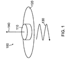
- Figure 1 illustrates generally a system 100 for rotationally biasing a fiber optic gyroscope assembly 110,such as part or all of an IFOG.
- gyroscope assembly 110 can include a fiber optic coil housed in a cylindrical shell as part of an IFOG, or can include the entire IFOG assembly.
- gyroscope assembly 110 is mounted on a motorized platform 120, to which a dither motion 130 is applied about the gyro input axis 140, thereby imparting a biasing phasemodulation to the counter-propagating optical signals in the fiber optic coil of gyroscope assembly 110.
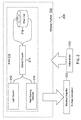
- FIG. 2 illustrates further details of a system 200 for rotationally biasing a fiber optic gyroscope such as an IFOG 210 according to one embodiment.
- the basic architecture of IFOG 210 includes a light source 212, such as a laser,fiber light source,or a superluminescent diode (SLD); a rate sensing detector 214; an optical coupler 216 such as a 2x2 optical coupler; and a fiber optic coil 218.
- the light source 212 and rate sensing detector 214 are each in optical communication with fiber optic coil 218 through optical fibers or waveguides coupled to optical coupler 216.
- the fiber optic coil 218 is configured to impart a phase shift proportional to rotation.
- light source 212 transmits an optical signal to fiber optic coil 218 through optical coupler 216.
- a returning optical signal is sent from fiber optic coil 218 back through optical coupler 216, which directs the returning optical signal to rate sensing detector 214.
- the rate sensing detector 214 converts the optical signal to an electrical signal that is sent to an electrical amplifier 220, which directs the amplified electrical signal to a processor for rotation rate calculation.
- the IFOG 210 is mounted on a dithered platform 230, which is configured to impart a periodic bias rotation angle to IFOG 210.
- the platform 230 can be coupled to a dither motor 232, such as a stepper motor or piezo-electric motor, which imparts a periodic mechanical dither at an appropriate frequency for fiber optic coil 218.
- dither motor 232 can produce high frequency displacement of fiber optic coil 218 through acoustic or ultrasonic vibration.
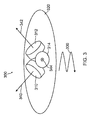
- Figure 3 illustrates generally a system 300 for rotationally biasing multiple fiber optic gyroscope assemblies 310, 312, and 314, which can include portions or all of multiple IFOG assemblies that are part of a three-axis IMU.
- gyroscope assemblies 310, 312, and 314 can each include respective fiber optic coils housed in cylindrical shells as part of respective IFOGs, or can include the entire IFOG assemblies.
- gyroscope assemblies 310, 312, and 314 having substantiallyorthogonal input axes 340, 342, and 344 respectively, are mounted on a common motorized platform 320.
- a dither motion 330 is applied to platform 320 to impart a biasing rotation angle to gyroscope assemblies 310, 312, and 314.
- the biasing rotation angle of platform 320 can be measured with anoptical encoder, piezo-electric transducer, or the like.
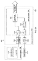
- Figure 4 illustrates further details of a system 400 for rotationally biasing multiple fiber optic gyroscope assemblies in a full attitude reference apparatus 410, such as a three-axis IMU, according to one embodiment.
- the basic architecture of reference apparatus 410 includes a light source 412, such as a laser fiber light source or an SLD, an optical splitter 413 such as a 1x3 optical splitter, a set of optical couplers414a, 414b, 414c, such as 2x2 optical couplers, a set of fiber optic coils416a, 416b, 416c, such as an x-axis coil, a y-axis coil, and a z-axis coil, and a set of rate sensing detectors 418a, 418b, 418c, such as an x-axis detector, a y-axis detector, and a z-axis detector.
- the light source and rate sensing detectors are each in optical communication with the fiber optic coils through optical
- light source 412 transmits an optical signal to optical splitter 413, which transmits portions of the optical signal to each of optical couplers 414a, 414b, 414c, which in turn transmit the respective portions of the optical signal to fiber optic coils416a, 416b, 416c.
- Returning optical signals are sent from each of fiber optic coil 416a, 416b, 416c back through respective optical couplers414a, 414b, 414c, which directs the returning optical signals to respective rate sensing detectors418a, 418b, 418c.
- the rate sensing detectors then convert the respective optical signals to electrical signalsthat are used for rate calculationof each individual axis.
- the reference apparatus 410 is mounted on a dithered platform 430, which is configured to impart a dither rotation angle to reference apparatus 410.
- the platform 430 can be coupled to a dither motor 432, such as a stepper motor or piezo-electric motor, and is oriented such that the dither rotation has a component parallel to the input axes of each of the fiber coils.
- platform 430 can be oriented to be at the apex of a three axis pyramid so that the dither rotation is applied at about 45 degrees to each coil input axis.
- FIG. 5A is a block diagram illustrating a system 500 for rotationally biasing a fiber optic gyroscope such as an IFOG 510 according to one embodiment.
- the system 500 includes a signal processing unit 520 that can be employed with IFOG 510 for single axisprocessing.In general, the rate signal from IFOG 510 is demodulated with the same waveform generator used to create a dither.
- the IFOG 510 is mounted on a dithered platform 512, which is configured to impart a bias rotation angle to IFOG 510.
- the dithered platform 512 is responsive to a dither actuator 514 that is coupled with signal processing unit 520.
- the signal processing unit 520 is configured to convert a measured intensity of the optical signal from IFOG 510 to rotation rate data.
- the signal processing unit 520 includes a measurement electronics section 522 and a digital section 524 that can be implemented in firmware, for example.
- a dither drive generator 530 in digital section 524 sends a digital drive signal to a digital to analog (D/A) converter 531, which sends an analog drive signal to a drive amplifier 532 in measurement electronics section 522.
- An amplified drive signal is output from drive amplifier 532 to dither actuator 514.
- D/A digital to analog
- a rate sensing photodetector 516 on IFOG 510 outputs a rate signal to a trans-impedance amplifier 534 in measurement electronics section 522.
- the amplified rate signal from trans-impedance amplifier 534 is sent to an analog to digital (A/D) converter 536, which sends a digital rate signal to a rate signal demodulation unit 538 in digital section 524.
- the rate signal demodulation unit 538 also receives the drive signal from dither drive generator 530.
- the rate signal from IFOG 510 is demodulated by the dither signal in rate signal demodulation unit 538.
- the gyro rate is then output from signal processing unit 520 to a processing system for further use.
- FIG. 5B illustrates a system 550 for rotationally biasing a fiber optic gyroscope such as IFOG 510, according to an alternative embodiment, in which a signal processing unit 560 is implemented with analog components for single axis processing.
- the rate signal from IFOG 510 is again demodulated with the same waveform generator used to create a dither.
- IFOG 510 is mounted on dithered platform 512, which is configured to impart a bias rotation angle to IFOG 510, and dithered platform 512 is responsive to dither actuator 514 that is coupled with signal processing unit 560.
- the signal processing unit 560 includes an analog measurement and drive electronics section 562, and a rate signal demodulation section 570.
- the drive electronics section 562 includes a dither drive generator 564, which sends a dither drive signal to a drive amplifier 566 and to rate signal demodulation section 570.
- An amplified dither drive signal is output from drive amplifier 566 to dither actuator 514.
- the rate sensing photodetector 516 on IFOG 510 outputs a rate signal to a trans-impedance amplifier 568 in drive electronics section 562.
- the amplified rate signal from trans-impedance amplifier 568 is sent to a mixer 572 in rate signal demodulation section 570.
- the mixer 572 also receives the dither drive signal from dither drive generator 564.
- a mixed rate signal from mixer 572 is then sent to a low pass filter 574, which outputs a demodulated rate signal that is used to output a gyro rate from rate signal demodulation section 570.
- FIG. 6A is a block diagram illustrating a system 600 for rotationally biasing a fiber optic gyroscope such as an IFOG 610 according to another embodiment.
- the system 600 includes a signal processing unit 620 that can be employed with IFOG 610 for single axis processing.In general, the rate signal from IFOG 610 is demodulated by a measured dither signal.
- the IFOG 610 is mounted on a dithered platform 612, which is configured to impart a bias rotation angle to IFOG 610.
- the dithered platform 612 is responsive to a dither actuator 614 that is coupled with signal processing unit 620.
- An angle sensor 616 such as a piezo-electric transducer or an optical encoder, is mounted on dithered platform 612. The angle sensor 616 is used to measure a local angle of dithered platform 612with respect to a surface on which dithered platform 612 is mounted.
- the signal processing unit620 includes a measurement electronics section 622 and a digital section 624 that can be implemented in firmware, for example.
- a dither drive generator 630 in digital section 624 sends a digital drive signal to a D/A converter 631, which sends an analog drive signal to a drive amplifier 632 in measurement electronics section 622.
- An amplified drive signal is output from drive amplifier 632 to dither actuator 614.
- a rate sensing photodetector 618 on IFOG 610 outputs a rate signal to a trans-impedance amplifier 634 in measurement electronics section 622.
- the amplified rate signal from trans-impedance amplifier 634 is sent to a first A/D converter 636, which outputs a digital rate signal to a rate signal demodulation unit 638.
- the angle sensor 616 on dithered platform 612 outputs a dither angle signal to anangle amplifier 642 in measurement electronics section 622.
- the angle amplifier 642 sends the amplified dither angle signal to a second A/D converter 644, which outputs a digital dither signal to a dither angle calculation module 646.
- the rate of the amplified signal from rate sensing photodetector 618, via A/D converter 636, is rectified in rate signal demodulation unit 638 using the calculated dither angle from dither angle calculation module 646.
- a gyro rate is then output from signal processing unit 620 for further use.
- FIG. 6B illustrates a system 650 for rotationally biasing a fiber optic gyroscope such as IFOG 610, according to an alternative embodiment, in which a signal processing unit 660 is implemented with analog components for single axis processing.
- the rate signal from IFOG 610 is again demodulated using the measured dither signal.
- the IFOG 610 is mounted on dithered platform 612, which is configured to impart a bias rotation angle to IFOG 610, and dithered platform 612 is responsive to dither actuator 614 that is coupled with signal processing unit 660.
- the angle sensor 616 mounted on dithered platform 612 is again used to measure the angle of dithered platform 612.
- the signal processing unit 660 includes an analog measurement and drive electronics section 662, and a rate signal demodulation section 670.
- the drive electronics section 662 includes a dither drive generator 664, which sends a dither drive signal to a drive amplifier 666.
- An amplified dither drive signal is output from drive amplifier 666 to dither actuator 614.
- the rate sensing photodetector 618 on IFOG 610 outputs a rate signal to a trans-impedance amplifier 668 in drive electronics section 662.
- the amplified rate signal from trans-impedance amplifier 668 is sent to a mixer 672 in rate signal demodulation section 670.
- the angle sensor 616 on dithered platform 612 outputs a dither signal to an angle amplifier 669 in measurement electronics section 662.
- the angle amplifier 669 sends the amplified dither signal to mixer 672.
- a mixed rate signal from mixer 672 is then sent to a low pass filter 674, which outputs a demodulated rate signal that is used to output a gyro rate signal from rate signal demodulation section 670.
- the rate signal demodulation section 670 strips out imperfections in dither actuator 614 and angle amplifier 669.
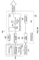
- FIG. 7 is a block diagram illustrating a system 700 for rotationally biasing a fiber optic gyroscope such as IFOG 610 according to another embodiment.
- the system 700 includes a signal processing unit720 that can be employed with IFOG 610 for single axis processing.
- the IFOG 610 is again mounted on dithered platform 612, which is configured to impart a bias rotation angle to IFOG 610, and dithered platform 612is responsive to dither actuator 614 that is coupled with signal processing unit720.
- the angle sensor 616 mounted on dithered platform 612 is again used to measure the angle of dithered platform 612.
- the signal processing unit720 includes a measurement electronics section 722 and a digital section 724 that can be implemented in firmware, for example.
- a dither drive generator 730 receives a signal from a static dither generator 732 and outputs a digital drive signal to a D/A converter 733, which sends an analog drive signal to a drive amplifier 734 in measurement electronics section 722.
- An amplified drive signal is output from drive amplifier 734 to dither actuator 614.
- the rate sensing photodetector 618 on IFOG 610 outputs a rate signal to a trans-impedance amplifier 735 in measurement electronics section 722.
- the amplified rate signal from trans-impedance amplifier 735 is sent to an A/D converter 736, which outputs a digital rate signal to a rate signal demodulation unit 738 and an intensity signal demodulation unit 740 in digital section 724.
- the angle sensor 616 on dithered platform 612 outputs a dither signal to an angleamplifier 742 in measurement electronics section 722.
- the angle amplifier 742 sends the amplified dither signal to an A/D converter 744, which outputs a digital dither signal to a dither angle calculation module746.
- the rate and intensity of the amplified signal returning from rate sensing photodetector 618, via A/D converter 736, is rectified in signal demodulation units 738 and 740 using the calculated dither angle from dither angle calculation module 746.
- the rate signal from IFOG 610 is demodulated in rate signal demodulation unit 738, and the intensitysignalfrom IFOG 610 is demodulated in intensity signal demodulation unit 740.
- a modulation depth calculation module 752 receives the demodulatedratesignals from both of signal demodulation units 738 and 740. The demodulated signals are used to calculate the effective modulation depth in order to keep the dither amplitude near an optimal operating value.
- the modulation depth calculation module 752 then outputs a modulation depth signal to a drive error correction module 754.
- the dither drive generator 730 is updated with a modulation depth error signal from error correction module 754, effectively forming a closed loop servo which corrects for any drive instability.
- a gyro ratesignal is output from digital section 724 of signal processing unit 720 for further use.
- I is the detected intensity at the rate sensing detector
- ⁇ is the total phase shift due to both biasing rotation of the dithered platform and rotation of the sensor.
- ⁇ S is the Sagnac phase shift due to the rotation being measured
- Jn represents the n-th Bessel function of the 1st kind.
- Equation 12 defines the signal at the carrier frequency to be measured, because it issinusoidal in rate (i.e., it has sign discrimination and maximum sensitivity).
- Equation13 defines the demodulated signal at the intensity demodulation unit, wherein the second harmonic of the dither frequency gives a term, S 2 ⁇ , proportional to the cosineof the Sagnac phase shift: S 2 ⁇ ⁇ I 0 J 2 ⁇ cos ⁇ ⁇ s .
- the cos ⁇ S term becomes approximately equal to 1 and the demodulated signal is effectively proportional to only the optical intensity and the 2 nd Bessel function of the modulation depth. At a fixed optical intensity, this signal may be exploited to calculate the effective phase modulation depth of the dither.
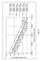
- Figure 8 is a graph illustrating the dither angular amplitude needed with respect to modulation frequency to achieve a maximum signal strength (peak of J 1 )for various fiber coil lengths and diameters.
- Figure 8 shows that for many practical lengths of fiber, the optimal dither frequency is within the useable range of standard piezo-electric transducers and motors capable of imparting rotational motion.
- a computer or processor used in the present system and method can be implemented using software, firmware, hardware, or any appropriate combination thereof, as known to one of skill in the art. These may be supplemented by, or incorporated in, specially-designed application-specific integrated circuits (ASICs) or field programmable gate arrays (FPGAs).
- ASICs application-specific integrated circuits
- FPGAs field programmable gate arrays
- the computer or processor can also include functions with software programs, firmware, or other computer readable instructions for carrying out various process tasks, calculations, and control functions used in the present method and system.
- the present methods can be implemented by computer executable instructions, such as program modules or components, which are executed by at least one processor.
- program modules include routines, programs, objects, data components, data structures, algorithms, and the like, which perform particular tasks or implement particular abstract data types.
- Instructions for carrying out the various process tasks, calculations, and generation of other data used in the operation of the methods described herein can be implemented in software, firmware, or other computer-or processor-readable instructions. These instructions are typically stored on any appropriate computer program product that includes a computer readable medium used for storage of computer readable instructions or data structures. Such a computer readable medium can be any available media that can be accessed by a general purpose or special purpose computer or processor, or any programmable logic device.
- Suitable processor-readable media may include storage or memory media such as magnetic or optical media.
- storage or memory media may include conventional hard disks, compact disks, DVDs, Blu-ray discs, or other optical storage disks; volatile or non-volatile media such as Random Access Memory (RAM); Read Only Memory (ROM), Electrically Erasable Programmable ROM (EEPROM), flash memory, and the like; or any other media that can be used to carry or store desired program code in the form of computer executable instructions or data structures.
- RAM Random Access Memory
- ROM Read Only Memory
- EEPROM Electrically Erasable Programmable ROM
- flash memory and the like
- any other media that can be used to carry or store desired program code in the form of computer executable instructions or data structures.
Landscapes
- Physics & Mathematics (AREA)
- Engineering & Computer Science (AREA)
- Power Engineering (AREA)
- Optics & Photonics (AREA)
- Electromagnetism (AREA)
- General Physics & Mathematics (AREA)
- Radar, Positioning & Navigation (AREA)
- Remote Sensing (AREA)
- Gyroscopes (AREA)
Abstract
Description
- The standard interferometric fiber optic gyroscope (IFOG) requires some mechanism for phase modulating in order to move the operating point of the interferometer onto the more sensitive points of the intensity versus phase curve, at which there is also sign differentiation. The standard method of imparting a biasing phase modulation to counter propagating light waves in an IFOG is to use an optical phase modulator, such as a lithium niobate electro-optic modulator or a fiber-stretching piezo modulator. Since both of these technologies are direct optical phase modulators, they operate in the optical path and can have unwanted side effects, such as residual intensity modulation, optical attenuation, wavelength dependent loss, and the like.
- A system for rotationally biasing a fiber optic gyroscope is provided. The system includes a fiber optic gyroscope assembly that comprises a light source configured to emit an optical signal, an optical coupler in optical communication with the light source, and a fiber optic coil in optical communication with the light source.The fiber optic coil is configured to receive the optical signal through the optical coupler and impart a phase shift proportional to rotation. A rate sensing detector in optical communication with the fiber optic coil is configured to receive the optical signal from the fiber optic coil through the optical coupler. A motor operatively coupled to the fiber optic coil is configured to apply a periodic rotation to the fiber optic coil to impart a biasing phase modulation to the optical signal. A signal processing unit is operatively coupled to the fiber optic gyroscope assembly and the motor. The signal processing unit is configured to convert a measured intensity of the optical signal to rotation rate data.
- Features of the present invention will become apparent to those skilled in the art from the following description with reference to the drawings. Understanding that the drawings depict only typical embodiments and are not therefore to be considered limiting in scope, the invention will be described with additional specificity and detail through the use of the accompanying drawings, in which:
-
Figure 1 is a schematic diagram of a system for rotationally biasing a fiber optic gyroscope according to one embodiment; -
Figure 2 is a block diagram of a system for rotationally biasing a fiber optic gyroscope according to one embodiment; -
Figure 3 is a schematic diagram of a system for rotationally biasing a fiber optic gyroscope according to another embodiment; -
Figure 4 is a block diagram of a system for rotationally biasing a fiber optic gyroscope according to another embodiment; -
Figure 5A is a block diagram illustrating a system for rotationally biasing a fiber optic gyroscope according to a further embodiment; -
Figure 5B is a block diagram illustrating a system for rotationally biasing a fiber optic gyroscope according to an alternative embodiment; -
Figure 6A is a block diagram illustrating a system for rotationally biasing a fiber optic gyroscope according to another embodiment; -
Figure 6B is a block diagram illustrating a system for rotationally biasing a fiber optic gyroscope according to an alternative embodiment; -
Figure 7 is a block diagram illustrating a system for rotationally biasing a fiber optic gyroscope according to a further embodiment;and -
Figure 8 is a graph showing the dither angular amplitude needed with respect to modulation frequency to achieve a maximum signal strength in a fiber optic gyroscope. - In the following detailed description, embodiments are described in sufficient detail to enable those skilled in the art to practice the invention. It is to be understood that other embodiments may be utilized without departing from the scope of the invention. The following detailed description is, therefore, not to be taken in a limiting sense.
- A system and method for rotationally biasing a fiber optic gyroscope are provided that increases the sensitivity of the fiber optic gyroscope. The system and methodprovide a mechanical bias modulation technique for the fiber optic gyroscope, such as an IFOG,which employs phase biasing through rotation (Sagnac effect).
- In one approach, a fiber optic coil of the IFOG is physically rotated or dithered through a known, periodic angle in order to increase the sensitivity to an unknown rotation rate that is being measured. Physically rotating or dithering the fiber optic coil requires no intrusion into the optical path, such as by using an optical phase modulator,and therefore has zero excess optical loss and secondary effects.
- In another approach, a single rotation can be used to simultaneously bias multiple fiber optic coils having orthogonal input axes, such as in an inertial measurement unit (IMU), by applying the rotation to a common mounting platform. This is in contrast to the state-of-the-art in which a single phase modulator must be used for a single fiber optic coil.
- The present system generally includes a light source that generates an optical signal, a fiber optic coil optically coupled to the light source and configured to impart a Sagnac phase shift proportional to rotation, and a motor that periodically rotates, vibrates, or dithers the fiber optic coil to impart a biasing phase modulation to the optical signal. The system also includes a fiber optic gyroscope front/back-end comprised of a splitter/recombiner (for the counter-propagating optical waves), photodetector (for interfering the signals), and signal processing electronics for converting the measured intensity to equivalent rotation.
- In one embodiment, biasing rotation of the IFOG can be accomplished by a dither motor mounted on the fiber coil hub. Alternatively, a dither motor can be mounted on a common platform to simultaneously bias multiple fiber optic coils or an entire IMU. A further enhancement may be implemented by using an optical encoder, piezo-electric transducer, or other mechanism for detecting the biasing rotation angle from the rotated platform, and using that measured rotation angle signal in demodulating the detected intensity.
- Further details of the present system and method are described hereafter with reference to the drawings.
-
Figure 1 illustrates generally asystem 100 for rotationally biasing a fiberoptic gyroscope assembly 110,such as part or all of an IFOG. For example,gyroscope assembly 110 can include a fiber optic coil housed in a cylindrical shell as part of an IFOG, or can include the entire IFOG assembly. In one embodiment,gyroscope assembly 110 is mounted on amotorized platform 120, to which adither motion 130 is applied about thegyro input axis 140, thereby imparting a biasing phasemodulation to the counter-propagating optical signals in the fiber optic coil ofgyroscope assembly 110. -
Figure 2 illustrates further details of asystem 200 for rotationally biasing a fiber optic gyroscope such as an IFOG 210 according to one embodiment. The basic architecture of IFOG 210 includes alight source 212, such as a laser,fiber light source,or a superluminescent diode (SLD); arate sensing detector 214; anoptical coupler 216 such as a 2x2 optical coupler; and a fiberoptic coil 218. Thelight source 212 andrate sensing detector 214 are each in optical communication with fiberoptic coil 218 through optical fibers or waveguides coupled to optical coupler 216.The fiberoptic coil 218 is configured to impart a phase shift proportional to rotation. - During operation,
light source 212 transmits an optical signal to fiberoptic coil 218 throughoptical coupler 216. A returning optical signal is sent from fiberoptic coil 218 back throughoptical coupler 216, which directs the returning optical signal to ratesensing detector 214. Therate sensing detector 214 converts the optical signal to an electrical signal that is sent to anelectrical amplifier 220, which directs the amplified electrical signal to a processor for rotation rate calculation. - The IFOG 210 is mounted on a
dithered platform 230, which is configured to impart a periodic bias rotation angle to IFOG 210. Theplatform 230 can be coupled to adither motor 232, such as a stepper motor or piezo-electric motor, which imparts a periodic mechanical dither at an appropriate frequency for fiberoptic coil 218. For example,dither motor 232 can produce high frequency displacement of fiberoptic coil 218 through acoustic or ultrasonic vibration. -
Figure 3 illustrates generally asystem 300 for rotationally biasing multiple fiberoptic gyroscope assemblies gyroscope assemblies gyroscope assemblies substantiallyorthogonal input axes A dither motion 330 is applied toplatform 320 to impart a biasing rotation angle togyroscope assemblies platform 320 can be measured with anoptical encoder, piezo-electric transducer, or the like. -
Figure 4 illustrates further details of asystem 400 for rotationally biasing multiple fiber optic gyroscope assemblies in a fullattitude reference apparatus 410, such as a three-axis IMU, according to one embodiment. The basic architecture ofreference apparatus 410 includes alight source 412, such as a laser fiber light source or an SLD, anoptical splitter 413 such as a 1x3 optical splitter, a set of optical couplers414a, 414b, 414c, such as 2x2 optical couplers, a set of fiber optic coils416a, 416b, 416c, such as an x-axis coil, a y-axis coil, and a z-axis coil, and a set ofrate sensing detectors - During operation,
light source 412 transmits an optical signal tooptical splitter 413, which transmits portions of the optical signal to each ofoptical couplers optic coil - The
reference apparatus 410 is mounted on adithered platform 430, which is configured to impart a dither rotation angle toreference apparatus 410. Theplatform 430 can be coupled to adither motor 432, such as a stepper motor or piezo-electric motor, and is oriented such that the dither rotation has a component parallel to the input axes of each of the fiber coils. In one embodiment,platform 430 can be oriented to be at the apex of a three axis pyramid so that the dither rotation is applied at about 45 degrees to each coil input axis. -
Figure 5A is a block diagram illustrating asystem 500 for rotationally biasing a fiber optic gyroscope such as an IFOG 510 according to one embodiment. Thesystem 500 includes asignal processing unit 520 that can be employed withIFOG 510 for single axisprocessing.In general, the rate signal fromIFOG 510 is demodulated with the same waveform generator used to create a dither. TheIFOG 510 is mounted on a ditheredplatform 512, which is configured to impart a bias rotation angle toIFOG 510. The ditheredplatform 512 is responsive to adither actuator 514 that is coupled withsignal processing unit 520. Thesignal processing unit 520 is configured to convert a measured intensity of the optical signal fromIFOG 510 to rotation rate data. - The
signal processing unit 520 includes ameasurement electronics section 522 and adigital section 524 that can be implemented in firmware, for example. Adither drive generator 530 indigital section 524 sends a digital drive signal to a digital to analog (D/A)converter 531, which sends an analog drive signal to adrive amplifier 532 inmeasurement electronics section 522. An amplified drive signal is output fromdrive amplifier 532 to ditheractuator 514. - A
rate sensing photodetector 516 onIFOG 510 outputs a rate signal to a trans-impedance amplifier 534 inmeasurement electronics section 522. The amplified rate signal from trans-impedance amplifier 534 is sent to an analog to digital (A/D)converter 536, which sends a digital rate signal to a ratesignal demodulation unit 538 indigital section 524. The ratesignal demodulation unit 538 also receives the drive signal fromdither drive generator 530. The rate signal fromIFOG 510 is demodulated by the dither signal in rate signal demodulation unit 538.The gyro rate is then output fromsignal processing unit 520 to a processing system for further use. -
Figure 5B illustrates asystem 550 for rotationally biasing a fiber optic gyroscope such asIFOG 510, according to an alternative embodiment, in which asignal processing unit 560 is implemented with analog components for single axis processing. In general, the rate signal fromIFOG 510 is again demodulated with the same waveform generator used to create a dither. Again,IFOG 510 is mounted on ditheredplatform 512, which is configured to impart a bias rotation angle toIFOG 510, and ditheredplatform 512 is responsive to ditheractuator 514 that is coupled withsignal processing unit 560. - The
signal processing unit 560 includes an analog measurement and driveelectronics section 562, and a ratesignal demodulation section 570. Thedrive electronics section 562 includes adither drive generator 564, which sends a dither drive signal to adrive amplifier 566 and to ratesignal demodulation section 570. An amplified dither drive signal is output fromdrive amplifier 566 to ditheractuator 514. - The
rate sensing photodetector 516 onIFOG 510 outputs a rate signal to a trans-impedance amplifier 568 indrive electronics section 562. The amplified rate signal from trans-impedance amplifier 568 is sent to amixer 572 in ratesignal demodulation section 570. Themixer 572 also receives the dither drive signal from dither drive generator 564.A mixed rate signal frommixer 572 is then sent to alow pass filter 574, which outputs a demodulated rate signal that is used to output a gyro rate from ratesignal demodulation section 570. -
Figure 6A is a block diagram illustrating asystem 600 for rotationally biasing a fiber optic gyroscope such as anIFOG 610 according to another embodiment. Thesystem 600 includes asignal processing unit 620 that can be employed withIFOG 610 for single axis processing.In general, the rate signal fromIFOG 610 is demodulated by a measured dither signal. TheIFOG 610 is mounted on a ditheredplatform 612, which is configured to impart a bias rotation angle toIFOG 610. The ditheredplatform 612 is responsive to adither actuator 614 that is coupled withsignal processing unit 620. Anangle sensor 616, such as a piezo-electric transducer or an optical encoder, is mounted on ditheredplatform 612. Theangle sensor 616 is used to measure a local angle of dithered platform 612with respect to a surface on which ditheredplatform 612 is mounted. - The signal processing unit620 includes a
measurement electronics section 622 and adigital section 624 that can be implemented in firmware, for example. Adither drive generator 630 indigital section 624 sends a digital drive signal to a D/A converter 631, which sends an analog drive signal to adrive amplifier 632 inmeasurement electronics section 622. An amplified drive signal is output fromdrive amplifier 632 to ditheractuator 614. - A
rate sensing photodetector 618 onIFOG 610 outputs a rate signal to a trans-impedance amplifier 634 inmeasurement electronics section 622. The amplified rate signal from trans-impedance amplifier 634 is sent to a first A/D converter 636, which outputs a digital rate signal to a ratesignal demodulation unit 638. - The
angle sensor 616 on ditheredplatform 612 outputs a dither angle signal toanangle amplifier 642 inmeasurement electronics section 622. Theangle amplifier 642 sends the amplified dither angle signal to a second A/D converter 644, which outputs a digital dither signal to a ditherangle calculation module 646. The rate of the amplified signal fromrate sensing photodetector 618, via A/D converter 636, is rectified in ratesignal demodulation unit 638 using the calculated dither angle from ditherangle calculation module 646. A gyro rate is then output fromsignal processing unit 620 for further use. -
Figure 6B illustrates asystem 650 for rotationally biasing a fiber optic gyroscope such asIFOG 610, according to an alternative embodiment, in which asignal processing unit 660 is implemented with analog components for single axis processing. In general, the rate signal fromIFOG 610 is again demodulated using the measured dither signal. TheIFOG 610 is mounted on ditheredplatform 612, which is configured to impart a bias rotation angle toIFOG 610, and ditheredplatform 612 is responsive to ditheractuator 614 that is coupled with signal processing unit 660.Theangle sensor 616 mounted on ditheredplatform 612 is again used to measure the angle of ditheredplatform 612. - The
signal processing unit 660 includes an analog measurement and driveelectronics section 662, and a ratesignal demodulation section 670. Thedrive electronics section 662 includes adither drive generator 664, which sends a dither drive signal to adrive amplifier 666. An amplified dither drive signal is output fromdrive amplifier 666 to ditheractuator 614. - The
rate sensing photodetector 618 onIFOG 610 outputs a rate signal to a trans-impedance amplifier 668 indrive electronics section 662. The amplified rate signal from trans-impedance amplifier 668 is sent to amixer 672 in ratesignal demodulation section 670. Theangle sensor 616 on ditheredplatform 612 outputs a dither signal to anangle amplifier 669 inmeasurement electronics section 662. Theangle amplifier 669 sends the amplified dither signal tomixer 672. A mixed rate signal frommixer 672 is then sent to alow pass filter 674, which outputs a demodulated rate signal that is used to output a gyro rate signal from rate signal demodulation section 670.The ratesignal demodulation section 670 strips out imperfections indither actuator 614 andangle amplifier 669. -
Figure 7 is a block diagram illustrating asystem 700 for rotationally biasing a fiber optic gyroscope such asIFOG 610 according to another embodiment. Thesystem 700 includes a signal processing unit720 that can be employed withIFOG 610 for single axis processing. TheIFOG 610 is again mounted on ditheredplatform 612, which is configured to impart a bias rotation angle toIFOG 610, and dithered platform 612is responsive to ditheractuator 614 that is coupled with signal processing unit720. Theangle sensor 616 mounted on dithered platform 612is again used to measure the angle of ditheredplatform 612. - The signal processing unit720 includes a
measurement electronics section 722 and adigital section 724 that can be implemented in firmware, for example. Indigital section 724, adither drive generator 730 receives a signal from a static dither generator 732 and outputs a digital drive signal to a D/A converter 733, which sends an analog drive signal to adrive amplifier 734 inmeasurement electronics section 722. An amplified drive signal is output fromdrive amplifier 734 to ditheractuator 614. - The
rate sensing photodetector 618 onIFOG 610 outputs a rate signal to a trans-impedance amplifier 735 inmeasurement electronics section 722. The amplified rate signal from trans-impedance amplifier 735 is sent to an A/D converter 736, which outputs a digital rate signal to a ratesignal demodulation unit 738 and an intensitysignal demodulation unit 740 indigital section 724. - The
angle sensor 616 on ditheredplatform 612 outputs a dither signal to anangleamplifier 742 inmeasurement electronics section 722. Theangle amplifier 742 sends the amplified dither signal to an A/D converter 744, which outputs a digital dither signal to a dither angle calculation module746.The rate and intensity of the amplified signal returning fromrate sensing photodetector 618, via A/D converter 736, is rectified insignal demodulation units angle calculation module 746. - The rate signal from
IFOG 610 is demodulated in ratesignal demodulation unit 738, and theintensitysignalfrom IFOG 610 is demodulated in intensitysignal demodulation unit 740. By demodulation of the signal using the calculated dither angle, dither induced noise is effectively cancelled. - A modulation
depth calculation module 752 receives the demodulatedratesignals from both ofsignal demodulation units error correction module 754. Thedither drive generator 730 is updated with a modulation depth error signal fromerror correction module 754, effectively forming a closed loop servo which corrects for any drive instability.A gyro ratesignal is output fromdigital section 724 ofsignal processing unit 720 for further use. - The following equations illustrate the signal processing functions used in rotationally biasing an IFOG according to the present approach. The phase dependent portion of the interference pattern at the rate sensing detector can be defined by the following equation, for the simplest case in which power is evenly split between the two branches of the optical coil:


-
Figure 8 is a graph illustrating the dither angular amplitude needed with respect to modulation frequency to achieve a maximum signal strength (peak of J1)for various fiber coil lengths and diameters.Figure 8 shows that for many practical lengths of fiber, the optimal dither frequency is within the useable range of standard piezo-electric transducers and motors capable of imparting rotational motion. - A computer or processor used in the present system and method can be implemented using software, firmware, hardware, or any appropriate combination thereof, as known to one of skill in the art. These may be supplemented by, or incorporated in, specially-designed application-specific integrated circuits (ASICs) or field programmable gate arrays (FPGAs). The computer or processor can also include functions with software programs, firmware, or other computer readable instructions for carrying out various process tasks, calculations, and control functions used in the present method and system.
- The present methods can be implemented by computer executable instructions, such as program modules or components, which are executed by at least one processor. Generally, program modules include routines, programs, objects, data components, data structures, algorithms, and the like, which perform particular tasks or implement particular abstract data types.
- Instructions for carrying out the various process tasks, calculations, and generation of other data used in the operation of the methods described herein can be implemented in software, firmware, or other computer-or processor-readable instructions. These instructions are typically stored on any appropriate computer program product that includes a computer readable medium used for storage of computer readable instructions or data structures. Such a computer readable medium can be any available media that can be accessed by a general purpose or special purpose computer or processor, or any programmable logic device.
- Suitable processor-readable media may include storage or memory media such as magnetic or optical media. For example, storage or memory media may include conventional hard disks, compact disks, DVDs, Blu-ray discs, or other optical storage disks; volatile or non-volatile media such as Random Access Memory (RAM); Read Only Memory (ROM), Electrically Erasable Programmable ROM (EEPROM), flash memory, and the like; or any other media that can be used to carry or store desired program code in the form of computer executable instructions or data structures.
-
- Example 1 includes a system for rotationally biasing a fiber optic gyroscope, the system comprising: a fiber optic gyroscope assembly comprising a light source configured to emit an optical signal; an optical coupler in optical communication with the light source; a fiber optic coil in optical communication with the light source, the fiber optic coil configured to receive the optical signal through the optical coupler and impart a phase shift proportional to rotation; and a rate sensing detector in optical communication with the fiber optic coil and configured to receive the optical signal from the fiber optic coil through the optical coupler; a motor operatively coupled to the fiber optic coil and configured to apply a periodic rotation to the fiber optic coil to impart a biasing phase modulation to the optical signal; and a signal processing unitoperatively coupled to the fiber optic gyroscope assembly and the motor, the signal processing unit configured to convert a measured intensity of the optical signal to rotation rate data.
- Example 2 includes thesystem of Example1, further comprising a platform operatively coupled to the motor, wherein at least a portion of the fiber optic gyroscope assembly that includes the fiber optic coil is mountedon the platform.
- Example 3 includes thesystem of any of Examples 1-2, wherein the light source comprises a laser,a fiber light source, or a superluminescent diode.
- Example 4 includes the system of any of Examples 1-3, wherein the fiber optic gyroscope assembly comprises an interferometric fiber optic gyroscope (IFOG).
- Example 5 includes thesystem of any of Examples 1-4, wherein the motorimparts a periodic rotational motion to the platform.
- Example 6 includes thesystem of any of Examples 1-5, wherein the motor comprises a stepper motor or a piezo-electric motor.
- Example 7 includes thesystem of any of Examples 1-6, wherein the rate sensing detector converts the optical signal from the fiber optic coil to an electrical rate signal that is sent to the signal processing unit for rotation rate calculation.
- Example 8 includes thesystem of Example7, wherein the signal processing unitcomprises: a dither drive generator; a drive amplifier configured to receive a dither drive signal from the dither drive generator, the drive amplifier operatively coupled to a dither actuator on the motor; a trans-impedance amplifier configured to receive the electrical rate signal from the rate sensing detector; and a rate signal demodulation unit configured to receive an amplified rate signal from the trans-impedance amplifier and output a demodulated rate signal.
- Example 9 includes thesystem of Example8, wherein the dither drive generator sends a digital drive signal to a digital to analog converter, which outputs an analog drive signal to the drive amplifier; and the trans-impedance amplifier sends an amplified rate signal to an analog to digital converter, which outputs a digital rate signal to the rate signal demodulation unit to demodulate the rate signal via the dither drive signal.
- Example 10 includes thesystem of Examples 8, wherein the rate signal demodulation unit comprises: a mixer configured to receive the dither drive signal from the dither drive generator and the amplified rate signal from the trans-impedance amplifier; and a low pass filter configured to receive a mixed rate signal from the mixer, and outputthe rate signaldemodulatedvia the dither drive signal.
- Example 11 includes thesystem of Example 8, further comprising an angle sensor mounted on the platform, and the signal processing unitfurther comprising an angle amplifier configured to receive a dither angle signal from the angle sensor.
- Example 12 includes thesystem of Example11, wherein the dither drive generator sends a digital drive signal to a digital to analog converter, which outputs an analog drive signal to the drive amplifier; the trans-impedance amplifier sends an amplified rate signal to a first analog to digital converter, which outputs a digital rate signal to the rate signal demodulation unit; and the angle amplifier sends an amplified dither angle signal to a second analog to digital converter, which outputs a digital dither angle signal to a dither angle calculation module; wherein the rate signal demodulation unit receives a calculated dither angle signal from the dither angle calculation module, and rectifies the digital rate signal using the calculated dither angle.
- Example 13 includes thesystem of Example 11, wherein the rate signal demodulation unit comprises a mixer configured to receive the amplified rate signal from the trans-impedance amplifier, and an amplified dither angle signalfrom the angle amplifier; and a low pass filter configured to receive a mixed rate signal from the mixer, and outputthe rate signaldemodulatedvia the dither angle signal.
- Example 14 includes thesystem of Example 12, wherein the signal processing unitfurther comprises: an intensity signal demodulation unit configured to receive the digital rate signal from the first analog to digital converter, and the dither angle signal from the dither angle calculation module; a modulation depth calculation module configured to receive the demodulated rate signal from the signal demodulation unit, and a demodulated intensity signal from the intensity signal demodulation unit; and a drive error correction module configured to receive a modulation depth signal from the modulation depth calculation module; wherein the dither drive generator is updated with an error correction signal from the drive error correction module to keep a dither amplitude near an optimal operating value.
- Example 15 includes a system for rotationally biasing multiple fiber optic gyroscopes, the system comprising: a multi-axis fiber optic gyroscope assembly comprising at least one light source configured to emit an optical signal; a set of optical couplers each in optical communication with the light source; a set of fiber optic coils each in optical communication with the light source, the fiber optic coils each configured to receive the optical signal through a respective one of the optical couplers and impart a phase shift proportional to rotation; and aset of rate sensing detectorseach in optical communication with a respective one of the fiber optic coils, the rate sensing detectorseach configured to receive the optical signal from the respective one of the fiber optic coils through a respective one of the optical couplers; a platform on which at least a portion of the multi-axis fiber optic gyroscope assembly is mounted that includes the fiber optic coils; a dither motor operatively coupled to the platform and configured to apply a dithering motion to the platform to impart a periodic rotation having a rotational component along an input axis of each of the fiber optic coils, thereby imparting a biasing phase modulation to each of the optical signals; and a signal processing unitoperatively coupled to the multi-axis fiber optic gyroscope assembly and the dither motor, the signal processing unit configured to convert measured intensities of the optical signals to rotation rate data.
- Example 16 includes thesystem of Example15, wherein the multi-axis fiber optic gyroscope assembly comprises multiple interferometric fiber optic gyroscopes.
- Example 17 includes the system of any of Examples 15-16, wherein the fiber optic coils have substantially orthogonal input axes such that the multi-axis fiber optic gyroscope assembly comprises a full attitude reference apparatus.
- Example 18 includes the system of Example 17, wherein the platform is configured such that the dithering motion is applied at an angle of about 45 degrees to each coil axis.
- Example 19 includes a method for rotationally biasing one or more fiber optic gyroscopes, the method comprising: rotating a fiber optic coil of the one or more fiber optic gyroscopes through a predetermined periodic angle to impart a biasing phase modulation to an optical signal in the fiber optic coil; and converting a measured intensity of the optical signal to rotation rate data.
- Example 20 includes the method of Example 19, wherein the fiber optic gyroscopes are part of a multi-axis fiber optic gyroscope assembly in which the fiber optic coils have substantially orthogonal input axes.
- The present invention may be embodied in other specific forms without departing from its essential characteristics. The described embodiments are to be considered in all respects only as illustrative and not restrictive. The scope of the invention is therefore indicated by the appended claims rather than by the foregoing description. All changes that come within the meaning and range of equivalency of the claims are to be embraced within their scope.
Claims (10)
- Asystem for rotationally biasing a fiber optic gyroscope, the system comprising:a fiber optic gyroscope assembly comprising:a light source configured to emit an optical signal;at least one optical coupler in optical communication with the light source;at least one fiber optic coil in optical communication with the light source, the fiber optic coil configured to receive the optical signal through the optical coupler and impart a phase shift proportional to rotation; andat least one rate sensing detector in optical communication with the fiber optic coil and configured to receive the optical signal from the fiber optic coil through the optical coupler;a motor operatively coupled to the fiber optic coil and configured to apply a periodic rotation to the fiber optic coil to impart a biasing phase modulation to the optical signal; anda signal processing unitoperatively coupled to the fiber optic gyroscope assembly and the motor, the signal processing unit configured to convert a measured intensity of the optical signal to rotation rate data.
- The system of claim 1, wherein the signal processing unitcomprises:a dither drive generator;a drive amplifier configured to receive a dither drive signal from the dither drive generator, the drive amplifier operatively coupled to a dither actuator on the motor;a trans-impedance amplifier configured to receive the electrical rate signal from the rate sensing detector;anda rate signal demodulation unit configured to receive an amplified rate signal from the trans-impedance amplifier and output a demodulated rate signal.
- The system of claim 2, wherein:the dither drive generator sends a digital drive signal to a digital to analog converter, which outputs an analog drive signal to the drive amplifier;andthe trans-impedance amplifier sends an amplified rate signal to an analog to digital converter, which outputs a digital rate signal to the rate signal demodulation unit to demodulate the rate signal via the dither drive signal.
- The system of claim 2, wherein the rate signal demodulation unit comprises:a mixer configured to receive the dither drive signal from the dither drive generator and the amplified rate signal from the trans-impedance amplifier; anda low pass filter configured to receive a mixed rate signal from the mixer, and outputthe rate signaldemodulatedvia the dither drive signal.
- The system of claim 2, further comprising
a platform operatively coupled to the motor, wherein at least a portion of the fiber optic gyroscope assembly that includes the fiber optic coil is mountedon the platform;
an angle sensor mounted on the platform, the angle sensor configured to measure a local angle of the platform with respect to a surface on which the platform is mounted; and
the signal processing unitfurther comprising an angle amplifier configured to receive a dither angle signal from the angle sensor. - The system of claim 5, wherein:the dither drive generator sends a digital drive signal to a digital to analog converter, which outputs an analog drive signal to the drive amplifier;the trans-impedance amplifier sends an amplified rate signal to a first analog to digital converter, which outputs a digital rate signal to the rate signal demodulation unit;andthe angle amplifier sends an amplified dither angle signal to a second analog to digital converter, which outputs a digital dither angle signal to a dither angle calculation module;wherein the rate signal demodulation unit receives a calculated dither angle signal from the dither angle calculation module, and rectifies the digital rate signal using the calculated dither angle.
- The system of claim 5, wherein the rate signal demodulation unit comprises:a mixer configured to receive the amplified rate signal from the trans-impedance amplifier, and an amplified dither angle signalfrom the angle amplifier; anda low pass filter configured to receive a mixed rate signal from the mixer, and outputthe rate signaldemodulatedvia the dither angle signal.
- The system of claim 6, wherein the signal processing unitfurther comprises:an intensity signal demodulation unit configured to receive the digital rate signal from the first analog to digital converter, and the dither angle signal from the dither angle calculation module;a modulation depth calculation module configured to receive the demodulated rate signal from the signal demodulation unit, and a demodulated intensity signal from the intensity signal demodulation unit; anda drive error correction module configured to receive a modulation depth signal from the modulation depth calculation module;wherein the dither drive generator is updated with an error correction signal from the drive error correction module to keep a dither amplitude near an optimal operating value.
- The system of claim 1, wherein the fiber optic gyroscope assembly comprises multiple fiber optic coils having substantially orthogonal input axes with respect to each other.
- A method for rotationally biasing one or more fiber optic gyroscopes, the method comprising:rotating a fiber optic coil of the one or more fiber optic gyroscopes through a predetermined periodic angle to impart a biasing phase modulation to an optical signal in the fiber optic coil; andconverting a measured intensity of the optical signal to rotation rate data.
Applications Claiming Priority (1)
| Application Number | Priority Date | Filing Date | Title |
|---|---|---|---|
| US14/693,241 US9568318B2 (en) | 2015-04-22 | 2015-04-22 | Rotationally biased fiber optic gyroscope |
Publications (2)
| Publication Number | Publication Date |
|---|---|
| EP3086091A1 true EP3086091A1 (en) | 2016-10-26 |
| EP3086091B1 EP3086091B1 (en) | 2019-06-05 |
Family
ID=55745638
Family Applications (1)
| Application Number | Title | Priority Date | Filing Date |
|---|---|---|---|
| EP16164770.6A Active EP3086091B1 (en) | 2015-04-22 | 2016-04-11 | Rotationally biased fiber optic gyroscope |
Country Status (3)
| Country | Link |
|---|---|
| US (1) | US9568318B2 (en) |
| EP (1) | EP3086091B1 (en) |
| JP (1) | JP2016224032A (en) |
Families Citing this family (4)
| Publication number | Priority date | Publication date | Assignee | Title |
|---|---|---|---|---|
| US11047687B2 (en) * | 2017-01-13 | 2021-06-29 | The Charles Stark Draper Laboratory, Inc. | Fiber management assembly for multi-axis fiber optic gyroscope |
| US11656081B2 (en) * | 2019-10-18 | 2023-05-23 | Anello Photonics, Inc. | Integrated photonics optical gyroscopes optimized for autonomous terrestrial and aerial vehicles |
| US11371843B2 (en) * | 2020-07-02 | 2022-06-28 | Anello Photonics, Inc. | Integration of photonics optical gyroscopes with micro-electro-mechanical sensors |
| CN118293899B (en) * | 2024-06-05 | 2024-08-20 | 中国船舶集团有限公司第七〇七研究所 | Method for improving dynamic performance of fiber optic gyroscope |
Citations (5)
| Publication number | Priority date | Publication date | Assignee | Title |
|---|---|---|---|---|
| US4135822A (en) * | 1976-01-19 | 1979-01-23 | Massachusetts Institute Of Technology | Laser gyroscope |
| US4981359A (en) * | 1989-06-19 | 1991-01-01 | Litton Systems, Inc. | Ring laser gyroscope dither drive system and method |
| US5173745A (en) * | 1991-04-12 | 1992-12-22 | Honeywell Inc. | Cluster dither apparatus |
| US20090002712A1 (en) * | 2007-06-26 | 2009-01-01 | Huang Hung-Chia | Passively biased fiber-optic gyroscope and current sensor |
| CN103884352A (en) * | 2014-03-15 | 2014-06-25 | 浙江大学 | Method and device for automatically measuring output delay time of fiber-optic gyroscope |
Family Cites Families (12)
| Publication number | Priority date | Publication date | Assignee | Title |
|---|---|---|---|---|
| US5131750A (en) | 1990-06-04 | 1992-07-21 | Honeywell Inc. | Eigenfrequency phase shift control loop |
| US5159575A (en) | 1990-07-02 | 1992-10-27 | Winston Jr Charles R | Single stage demodulator with reference signal phase dither |
| US5416584A (en) | 1994-04-25 | 1995-05-16 | Honeywell Inc. | Sinusoidal noise injection into the dither of a ring laser gyroscope |
| US5684591A (en) | 1996-05-23 | 1997-11-04 | Alliedsignal Inc. | Fiber optic gyroscope with reduced non-linearity at low angular rates |
| US6002481A (en) | 1998-04-08 | 1999-12-14 | Honeywell, Inc. | Fiber optic gyro with noise dither circuit for enhancing A/D conversion resolution |
| FR2787878B1 (en) * | 1998-12-23 | 2001-03-16 | Sextant Avionique | ANTI-VIBRATION ELASTIC SUSPENSION FOR INERTIAL MEASUREMENT UNIT |
| JP2000329565A (en) * | 1999-03-16 | 2000-11-30 | Canon Inc | Gyro apparatus |
| US6476918B1 (en) | 2001-06-21 | 2002-11-05 | Honeywell International Inc. | Dither control system for a ring laser gyro |
| US7633626B2 (en) | 2006-12-13 | 2009-12-15 | Northrop Grumman Guidance and Electronics Co., Inc. | Fiber optic gyroscope deadband circumvention apparatus and method |
| US7548318B2 (en) | 2007-04-13 | 2009-06-16 | Custom Sensors & Technologies, Inc. | Dithering mechanism for eliminating zero-rate bias in a gyroscope |
| US7505140B2 (en) | 2007-04-13 | 2009-03-17 | Custom Sensors & Technologies, Inc. | Indexing dithering mechanism and method |
| US8542364B1 (en) * | 2009-12-17 | 2013-09-24 | Honeywell International Inc. | System to reduce gyroscopic errors with limited power supply quality in a fiber optic gyroscope |
-
2015
- 2015-04-22 US US14/693,241 patent/US9568318B2/en active Active
-
2016
- 2016-04-11 EP EP16164770.6A patent/EP3086091B1/en active Active
- 2016-04-18 JP JP2016082639A patent/JP2016224032A/en active Pending
Patent Citations (5)
| Publication number | Priority date | Publication date | Assignee | Title |
|---|---|---|---|---|
| US4135822A (en) * | 1976-01-19 | 1979-01-23 | Massachusetts Institute Of Technology | Laser gyroscope |
| US4981359A (en) * | 1989-06-19 | 1991-01-01 | Litton Systems, Inc. | Ring laser gyroscope dither drive system and method |
| US5173745A (en) * | 1991-04-12 | 1992-12-22 | Honeywell Inc. | Cluster dither apparatus |
| US20090002712A1 (en) * | 2007-06-26 | 2009-01-01 | Huang Hung-Chia | Passively biased fiber-optic gyroscope and current sensor |
| CN103884352A (en) * | 2014-03-15 | 2014-06-25 | 浙江大学 | Method and device for automatically measuring output delay time of fiber-optic gyroscope |
Also Published As
| Publication number | Publication date |
|---|---|
| JP2016224032A (en) | 2016-12-28 |
| US9568318B2 (en) | 2017-02-14 |
| US20160313125A1 (en) | 2016-10-27 |
| EP3086091B1 (en) | 2019-06-05 |
Similar Documents
| Publication | Publication Date | Title |
|---|---|---|
| US4545682A (en) | Optical gyroscope | |
| JP5784653B2 (en) | Transmission mode RFOG and method for detecting rotation in RFOG | |
| US7855789B2 (en) | RFOG modulation error correction | |
| US4708480A (en) | Solid-state optical interferometer | |
| EP2226612B1 (en) | Cavity length modulation in resonator fiber optic gyroscopes | |
| EP1044354B1 (en) | Fiber optic gyroscope | |
| EP3086091A1 (en) | Rotationally biased fiber optic gyroscope | |
| EP3011270B1 (en) | Dynamically monitoring the instantaneous zero rotation rate voltage of interferometric fiber optic gyroscope (ifog) | |
| EP1967819A2 (en) | Method of and system for vibration error suppression of fiber optic gyroscopes | |
| EP0990117B1 (en) | Fiber optic gyroscope vibration error compensator | |
| EP2005113B1 (en) | Power-servo controlled optical fiber based device, method of measuring and gyrometer | |
| US9157741B2 (en) | Simulator for simulating the operation of a fiber optic gyroscope | |
| US5237387A (en) | Dual serrodyne resonator fiber optic gyroscope | |
| US4408882A (en) | Optical gyroscope with time dependent wavelength | |
| EP0536306B1 (en) | Interferometric signal analysis with modulation switching | |
| Strandjord et al. | Resonator fiber optic gyro progress including observation of navigation grade angle random walk | |
| EP0511684B1 (en) | Phase modulated fibre-optic gyroscope | |
| US4432646A (en) | Angular velocity sensor based on a ring laser | |
| EP0223730A2 (en) | Method and apparatus for phase modulating a fiber-optic rotation sensor | |
| US5015095A (en) | Closed-loop fiber-optic angular rate sensor including a mixer arrangement for measuring rotational direction and rate | |
| Goss et al. | Fiber Optic Rotation Sensor (FORS) signal detection and processing | |
| US9267799B2 (en) | Method and apparatus of monitoring and tracking optical frequency differences of modulated beams | |
| RU82860U1 (en) | DEVICE FOR DETERMINING THE DIRECTION AND SPEED OF MOVEMENT OF THE EARTH AROUND THE CENTER OF THE GALAXY | |
| Khoshki et al. | Investigation on Closed-loop Fiber Optic Gyroscope Structure and Operation | |
| Celikel et al. | Optoelectronic design parameters of interferometric fiber optic gyroscope with LiNbO 3 having north finder capability and Earth rotation rate measurement |
Legal Events
| Date | Code | Title | Description |
|---|---|---|---|
| PUAI | Public reference made under article 153(3) epc to a published international application that has entered the european phase |
Free format text: ORIGINAL CODE: 0009012 |
|
| 17P | Request for examination filed |
Effective date: 20160411 |
|
| AK | Designated contracting states |
Kind code of ref document: A1 Designated state(s): AL AT BE BG CH CY CZ DE DK EE ES FI FR GB GR HR HU IE IS IT LI LT LU LV MC MK MT NL NO PL PT RO RS SE SI SK SM TR |
|
| AX | Request for extension of the european patent |
Extension state: BA ME |
|
| STAA | Information on the status of an ep patent application or granted ep patent |
Free format text: STATUS: EXAMINATION IS IN PROGRESS |
|
| 17Q | First examination report despatched |
Effective date: 20170725 |
|
| GRAP | Despatch of communication of intention to grant a patent |
Free format text: ORIGINAL CODE: EPIDOSNIGR1 |
|
| STAA | Information on the status of an ep patent application or granted ep patent |
Free format text: STATUS: GRANT OF PATENT IS INTENDED |
|
| INTG | Intention to grant announced |
Effective date: 20190103 |
|
| GRAS | Grant fee paid |
Free format text: ORIGINAL CODE: EPIDOSNIGR3 |
|
| GRAA | (expected) grant |
Free format text: ORIGINAL CODE: 0009210 |
|
| STAA | Information on the status of an ep patent application or granted ep patent |
Free format text: STATUS: THE PATENT HAS BEEN GRANTED |
|
| AK | Designated contracting states |
Kind code of ref document: B1 Designated state(s): AL AT BE BG CH CY CZ DE DK EE ES FI FR GB GR HR HU IE IS IT LI LT LU LV MC MK MT NL NO PL PT RO RS SE SI SK SM TR |
|
| REG | Reference to a national code |
Ref country code: GB Ref legal event code: FG4D |
|
| REG | Reference to a national code |
Ref country code: CH Ref legal event code: EP |
|
| REG | Reference to a national code |
Ref country code: AT Ref legal event code: REF Ref document number: 1140472 Country of ref document: AT Kind code of ref document: T Effective date: 20190615 |
|
| REG | Reference to a national code |
Ref country code: DE Ref legal event code: R096 Ref document number: 602016014693 Country of ref document: DE |
|
| REG | Reference to a national code |
Ref country code: IE Ref legal event code: FG4D |
|
| REG | Reference to a national code |
Ref country code: NL Ref legal event code: MP Effective date: 20190605 |
|
| REG | Reference to a national code |
Ref country code: LT Ref legal event code: MG4D |
|
| PG25 | Lapsed in a contracting state [announced via postgrant information from national office to epo] |
Ref country code: AL Free format text: LAPSE BECAUSE OF FAILURE TO SUBMIT A TRANSLATION OF THE DESCRIPTION OR TO PAY THE FEE WITHIN THE PRESCRIBED TIME-LIMIT Effective date: 20190605 Ref country code: ES Free format text: LAPSE BECAUSE OF FAILURE TO SUBMIT A TRANSLATION OF THE DESCRIPTION OR TO PAY THE FEE WITHIN THE PRESCRIBED TIME-LIMIT Effective date: 20190605 Ref country code: LT Free format text: LAPSE BECAUSE OF FAILURE TO SUBMIT A TRANSLATION OF THE DESCRIPTION OR TO PAY THE FEE WITHIN THE PRESCRIBED TIME-LIMIT Effective date: 20190605 Ref country code: FI Free format text: LAPSE BECAUSE OF FAILURE TO SUBMIT A TRANSLATION OF THE DESCRIPTION OR TO PAY THE FEE WITHIN THE PRESCRIBED TIME-LIMIT Effective date: 20190605 Ref country code: SE Free format text: LAPSE BECAUSE OF FAILURE TO SUBMIT A TRANSLATION OF THE DESCRIPTION OR TO PAY THE FEE WITHIN THE PRESCRIBED TIME-LIMIT Effective date: 20190605 Ref country code: HR Free format text: LAPSE BECAUSE OF FAILURE TO SUBMIT A TRANSLATION OF THE DESCRIPTION OR TO PAY THE FEE WITHIN THE PRESCRIBED TIME-LIMIT Effective date: 20190605 Ref country code: NO Free format text: LAPSE BECAUSE OF FAILURE TO SUBMIT A TRANSLATION OF THE DESCRIPTION OR TO PAY THE FEE WITHIN THE PRESCRIBED TIME-LIMIT Effective date: 20190905 |
|
| PG25 | Lapsed in a contracting state [announced via postgrant information from national office to epo] |
Ref country code: LV Free format text: LAPSE BECAUSE OF FAILURE TO SUBMIT A TRANSLATION OF THE DESCRIPTION OR TO PAY THE FEE WITHIN THE PRESCRIBED TIME-LIMIT Effective date: 20190605 Ref country code: GR Free format text: LAPSE BECAUSE OF FAILURE TO SUBMIT A TRANSLATION OF THE DESCRIPTION OR TO PAY THE FEE WITHIN THE PRESCRIBED TIME-LIMIT Effective date: 20190906 Ref country code: RS Free format text: LAPSE BECAUSE OF FAILURE TO SUBMIT A TRANSLATION OF THE DESCRIPTION OR TO PAY THE FEE WITHIN THE PRESCRIBED TIME-LIMIT Effective date: 20190605 Ref country code: BG Free format text: LAPSE BECAUSE OF FAILURE TO SUBMIT A TRANSLATION OF THE DESCRIPTION OR TO PAY THE FEE WITHIN THE PRESCRIBED TIME-LIMIT Effective date: 20190905 |
|
| REG | Reference to a national code |
Ref country code: AT Ref legal event code: MK05 Ref document number: 1140472 Country of ref document: AT Kind code of ref document: T Effective date: 20190605 |
|
| PG25 | Lapsed in a contracting state [announced via postgrant information from national office to epo] |
Ref country code: PT Free format text: LAPSE BECAUSE OF FAILURE TO SUBMIT A TRANSLATION OF THE DESCRIPTION OR TO PAY THE FEE WITHIN THE PRESCRIBED TIME-LIMIT Effective date: 20191007 Ref country code: AT Free format text: LAPSE BECAUSE OF FAILURE TO SUBMIT A TRANSLATION OF THE DESCRIPTION OR TO PAY THE FEE WITHIN THE PRESCRIBED TIME-LIMIT Effective date: 20190605 Ref country code: CZ Free format text: LAPSE BECAUSE OF FAILURE TO SUBMIT A TRANSLATION OF THE DESCRIPTION OR TO PAY THE FEE WITHIN THE PRESCRIBED TIME-LIMIT Effective date: 20190605 Ref country code: RO Free format text: LAPSE BECAUSE OF FAILURE TO SUBMIT A TRANSLATION OF THE DESCRIPTION OR TO PAY THE FEE WITHIN THE PRESCRIBED TIME-LIMIT Effective date: 20190605 Ref country code: NL Free format text: LAPSE BECAUSE OF FAILURE TO SUBMIT A TRANSLATION OF THE DESCRIPTION OR TO PAY THE FEE WITHIN THE PRESCRIBED TIME-LIMIT Effective date: 20190605 Ref country code: SK Free format text: LAPSE BECAUSE OF FAILURE TO SUBMIT A TRANSLATION OF THE DESCRIPTION OR TO PAY THE FEE WITHIN THE PRESCRIBED TIME-LIMIT Effective date: 20190605 Ref country code: EE Free format text: LAPSE BECAUSE OF FAILURE TO SUBMIT A TRANSLATION OF THE DESCRIPTION OR TO PAY THE FEE WITHIN THE PRESCRIBED TIME-LIMIT Effective date: 20190605 |
|
| PG25 | Lapsed in a contracting state [announced via postgrant information from national office to epo] |
Ref country code: IS Free format text: LAPSE BECAUSE OF FAILURE TO SUBMIT A TRANSLATION OF THE DESCRIPTION OR TO PAY THE FEE WITHIN THE PRESCRIBED TIME-LIMIT Effective date: 20191005 Ref country code: IT Free format text: LAPSE BECAUSE OF FAILURE TO SUBMIT A TRANSLATION OF THE DESCRIPTION OR TO PAY THE FEE WITHIN THE PRESCRIBED TIME-LIMIT Effective date: 20190605 Ref country code: SM Free format text: LAPSE BECAUSE OF FAILURE TO SUBMIT A TRANSLATION OF THE DESCRIPTION OR TO PAY THE FEE WITHIN THE PRESCRIBED TIME-LIMIT Effective date: 20190605 |
|
| REG | Reference to a national code |
Ref country code: DE Ref legal event code: R097 Ref document number: 602016014693 Country of ref document: DE |
|
| PG25 | Lapsed in a contracting state [announced via postgrant information from national office to epo] |
Ref country code: TR Free format text: LAPSE BECAUSE OF FAILURE TO SUBMIT A TRANSLATION OF THE DESCRIPTION OR TO PAY THE FEE WITHIN THE PRESCRIBED TIME-LIMIT Effective date: 20190605 |
|
| PLBE | No opposition filed within time limit |
Free format text: ORIGINAL CODE: 0009261 |
|
| STAA | Information on the status of an ep patent application or granted ep patent |
Free format text: STATUS: NO OPPOSITION FILED WITHIN TIME LIMIT |
|
| PG25 | Lapsed in a contracting state [announced via postgrant information from national office to epo] |
Ref country code: DK Free format text: LAPSE BECAUSE OF FAILURE TO SUBMIT A TRANSLATION OF THE DESCRIPTION OR TO PAY THE FEE WITHIN THE PRESCRIBED TIME-LIMIT Effective date: 20190605 Ref country code: PL Free format text: LAPSE BECAUSE OF FAILURE TO SUBMIT A TRANSLATION OF THE DESCRIPTION OR TO PAY THE FEE WITHIN THE PRESCRIBED TIME-LIMIT Effective date: 20190605 |
|
| 26N | No opposition filed |
Effective date: 20200306 |
|
| PG25 | Lapsed in a contracting state [announced via postgrant information from national office to epo] |
Ref country code: SI Free format text: LAPSE BECAUSE OF FAILURE TO SUBMIT A TRANSLATION OF THE DESCRIPTION OR TO PAY THE FEE WITHIN THE PRESCRIBED TIME-LIMIT Effective date: 20190605 |
|
| PGFP | Annual fee paid to national office [announced via postgrant information from national office to epo] |
Ref country code: DE Payment date: 20200430 Year of fee payment: 5 |
|
| PG25 | Lapsed in a contracting state [announced via postgrant information from national office to epo] |
Ref country code: MC Free format text: LAPSE BECAUSE OF FAILURE TO SUBMIT A TRANSLATION OF THE DESCRIPTION OR TO PAY THE FEE WITHIN THE PRESCRIBED TIME-LIMIT Effective date: 20190605 |
|
| REG | Reference to a national code |
Ref country code: CH Ref legal event code: PL |
|
| PG25 | Lapsed in a contracting state [announced via postgrant information from national office to epo] |
Ref country code: LU Free format text: LAPSE BECAUSE OF NON-PAYMENT OF DUE FEES Effective date: 20200411 Ref country code: CH Free format text: LAPSE BECAUSE OF NON-PAYMENT OF DUE FEES Effective date: 20200430 Ref country code: LI Free format text: LAPSE BECAUSE OF NON-PAYMENT OF DUE FEES Effective date: 20200430 |
|
| REG | Reference to a national code |
Ref country code: BE Ref legal event code: MM Effective date: 20200430 |
|
| PG25 | Lapsed in a contracting state [announced via postgrant information from national office to epo] |
Ref country code: BE Free format text: LAPSE BECAUSE OF NON-PAYMENT OF DUE FEES Effective date: 20200430 |
|
| GBPC | Gb: european patent ceased through non-payment of renewal fee |
Effective date: 20200411 |
|
| PG25 | Lapsed in a contracting state [announced via postgrant information from national office to epo] |
Ref country code: GB Free format text: LAPSE BECAUSE OF NON-PAYMENT OF DUE FEES Effective date: 20200411 Ref country code: IE Free format text: LAPSE BECAUSE OF NON-PAYMENT OF DUE FEES Effective date: 20200411 |
|
| REG | Reference to a national code |
Ref country code: DE Ref legal event code: R119 Ref document number: 602016014693 Country of ref document: DE |
|
| PG25 | Lapsed in a contracting state [announced via postgrant information from national office to epo] |
Ref country code: DE Free format text: LAPSE BECAUSE OF NON-PAYMENT OF DUE FEES Effective date: 20211103 |
|
| PG25 | Lapsed in a contracting state [announced via postgrant information from national office to epo] |
Ref country code: MT Free format text: LAPSE BECAUSE OF FAILURE TO SUBMIT A TRANSLATION OF THE DESCRIPTION OR TO PAY THE FEE WITHIN THE PRESCRIBED TIME-LIMIT Effective date: 20190605 Ref country code: CY Free format text: LAPSE BECAUSE OF FAILURE TO SUBMIT A TRANSLATION OF THE DESCRIPTION OR TO PAY THE FEE WITHIN THE PRESCRIBED TIME-LIMIT Effective date: 20190605 |
|
| PG25 | Lapsed in a contracting state [announced via postgrant information from national office to epo] |
Ref country code: MK Free format text: LAPSE BECAUSE OF FAILURE TO SUBMIT A TRANSLATION OF THE DESCRIPTION OR TO PAY THE FEE WITHIN THE PRESCRIBED TIME-LIMIT Effective date: 20190605 |
|
| P01 | Opt-out of the competence of the unified patent court (upc) registered |
Effective date: 20230525 |
|
| PGFP | Annual fee paid to national office [announced via postgrant information from national office to epo] |
Ref country code: FR Payment date: 20240430 Year of fee payment: 9 |