EP3085998A1 - Verfahren zur verabreichung eines schmierstoffes an ein drehflüglergetriebe - Google Patents
Verfahren zur verabreichung eines schmierstoffes an ein drehflüglergetriebe Download PDFInfo
- Publication number
- EP3085998A1 EP3085998A1 EP15170121.6A EP15170121A EP3085998A1 EP 3085998 A1 EP3085998 A1 EP 3085998A1 EP 15170121 A EP15170121 A EP 15170121A EP 3085998 A1 EP3085998 A1 EP 3085998A1
- Authority
- EP
- European Patent Office
- Prior art keywords
- rotorcraft
- gearbox
- parameter
- flow rate
- lubricant
- Prior art date
- Legal status (The legal status is an assumption and is not a legal conclusion. Google has not performed a legal analysis and makes no representation as to the accuracy of the status listed.)
- Granted
Links
Images

Classifications
-
- F—MECHANICAL ENGINEERING; LIGHTING; HEATING; WEAPONS; BLASTING
- F16—ENGINEERING ELEMENTS AND UNITS; GENERAL MEASURES FOR PRODUCING AND MAINTAINING EFFECTIVE FUNCTIONING OF MACHINES OR INSTALLATIONS; THERMAL INSULATION IN GENERAL
- F16H—GEARING
- F16H57/00—General details of gearing
- F16H57/04—Features relating to lubrication or cooling or heating
- F16H57/0434—Features relating to lubrication or cooling or heating relating to lubrication supply, e.g. pumps; Pressure control
- F16H57/0435—Pressure control for supplying lubricant; Circuits or valves therefor
-
- B—PERFORMING OPERATIONS; TRANSPORTING
- B64—AIRCRAFT; AVIATION; COSMONAUTICS
- B64C—AEROPLANES; HELICOPTERS
- B64C27/00—Rotorcraft; Rotors peculiar thereto
- B64C27/04—Helicopters
- B64C27/12—Rotor drives
-
- F—MECHANICAL ENGINEERING; LIGHTING; HEATING; WEAPONS; BLASTING
- F16—ENGINEERING ELEMENTS AND UNITS; GENERAL MEASURES FOR PRODUCING AND MAINTAINING EFFECTIVE FUNCTIONING OF MACHINES OR INSTALLATIONS; THERMAL INSULATION IN GENERAL
- F16H—GEARING
- F16H57/00—General details of gearing
- F16H57/04—Features relating to lubrication or cooling or heating
-
- F—MECHANICAL ENGINEERING; LIGHTING; HEATING; WEAPONS; BLASTING
- F16—ENGINEERING ELEMENTS AND UNITS; GENERAL MEASURES FOR PRODUCING AND MAINTAINING EFFECTIVE FUNCTIONING OF MACHINES OR INSTALLATIONS; THERMAL INSULATION IN GENERAL
- F16H—GEARING
- F16H57/00—General details of gearing
- F16H57/04—Features relating to lubrication or cooling or heating
- F16H57/0434—Features relating to lubrication or cooling or heating relating to lubrication supply, e.g. pumps; Pressure control
-
- F—MECHANICAL ENGINEERING; LIGHTING; HEATING; WEAPONS; BLASTING
- F16—ENGINEERING ELEMENTS AND UNITS; GENERAL MEASURES FOR PRODUCING AND MAINTAINING EFFECTIVE FUNCTIONING OF MACHINES OR INSTALLATIONS; THERMAL INSULATION IN GENERAL
- F16H—GEARING
- F16H57/00—General details of gearing
- F16H57/04—Features relating to lubrication or cooling or heating
- F16H57/048—Type of gearings to be lubricated, cooled or heated
- F16H57/0493—Gearings with spur or bevel gears
- F16H57/0495—Gearings with spur or bevel gears with fixed gear ratio
Definitions
- This invention relates generally to a rotorcraft, and more particularly, to a method for the delivery of lubricant to a rotorcraft gearbox.
- a rotorcraft may include one or more rotor systems.
- a rotorcraft rotor system is a main rotor system.
- a main rotor system may generate aerodynamic lift to support the weight of the rotorcraft in flight, and thrust to counteract aerodynamic drag and move the rotorcraft in forward flight.
- Another example of a rotorcraft rotor system is a tail rotor system.
- a tail rotor system may generate thrust in the same direction as the main rotor system's rotation to counter the torque effect created by the main rotor system.
- a rotor system may include a gearbox that transmits energy from a power source to the rotor blades.
- a technical advantage of one embodiment may include the capability to deliver lubricant to a gearbox when the rotorcraft experiences a reduction in lubricant pressure.
- a Rushal advantage of one embodiment may include the capability to reduce the friction experienced by the gearbox when the rotorcraft experiences a reduction in lubricant pressure.
- a technical advantage of one embodiment may include the capability to increase the amount of time that the rotorcraft can operate with a reduced lubricant pressure.
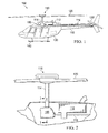
- FIGURE 1 shows a rotorcraft 100 according to one example embodiment.
- Rotorcraft 100 features power train system 110, main rotor blades 120, tail rotor blades 120', a fuselage 130, a landing gear 140, and an empennage 150.
- Power train system 110 may rotate blades 120 and/or blades 120'.
- FIGURE 2 shows the power train system 110 of FIGURE 1 .
- power train system 110 includes an engine 112, a gearbox 160, a rotor mast 114, and a tail rotor drive shaft 116.
- Engine 112 supplies torque to mast 114, via gearbox 160, for rotating of blades 120.
- Engine 112 also supplies torque to tail rotor drive shaft 116 for rotating blades 120'.
- gearbox 160 is a main rotor transmission system. Teachings of certain embodiments recognize, however, that power train system 110 may include more or different gearboxes than gearbox 160 shown in FIGURE 1 .
- Power train system 110 may include a control system for selectively controlling the pitch of each blade 120 in order to selectively control direction, thrust, and lift of rotorcraft 100.
- Fuselage 130 represents the body of rotorcraft 100 and may be coupled to power train system 110 such that power train system 110 and blades 120 may move fuselage 130 through the air.
- Landing gear 140 supports rotorcraft 100 when rotorcraft 100 is landing and/or when rotorcraft 100 is at rest on the ground.
- Empennage 150 represents the tail section of the aircraft and features blades 120'.
- Power train system 110 and blades 120' may collectively provide thrust in the same direction as the rotation of blades 120 so as to counter the torque effect created by blades 120. It should be appreciated that teachings from rotorcraft 100 may apply to aircraft other than rotorcraft, such as airplanes, tilt rotors, unmanned aircraft, to name a few examples. In addition, teachings of certain embodiments relating to rotor systems described herein may apply to power train system 110 and/or other power train systems, including but not limited to non-rotorcraft power train systems.
- a gearbox such as gearbox 160, may transmit power from a power source (e.g., engine 112) to an object to be moved.
- a gearbox may convert speed and torque between the power source and the object to be moved.
- One example of a gearbox may include a gearbox that can be configured to reduce the speed of the rotational output of the engine.
- a gearbox may include various gears and bearings.
- a gear is a rotating part having teeth that mesh with another toothed part in order to transmit torque.
- Gears in a gearbox may be used to provide speed and torque conversions.
- a bearing may include any of various machine elements that constrain the relative motion between two or more parts to only the desired motion. Bearings in a gearbox may perform tasks such as supporting a gear shaft.
- Gears, bearings, and other mechanical components of a gearbox are subject to wear and heat generation due to contact with other components. These mechanical components may be lubricated to reduce friction and transfer heat away from the components. Lubrication is the process or technique employed to reduce wear of one or both surfaces in close proximity, and moving relative to each other, by interposing a substance, such as lubricant, between the surfaces to help carry the load (pressure generated) between the opposing surfaces.
- a lubricant is a substance introduced to reduce friction between moving surfaces.
- examples of lubricants include oil, biolubricants derived from plants and animals, synthetic oils, solid lubricants, and aqueous lubricants.
- Example transmission oils for gearbox 160 may include oils meeting specifications MIL-PRF-23699 (5cSt), DOD-L-7808 (3-4cSt), DOD-PRF-85734 (5cSt), and other oils in the 9cSt to 10cSt viscosity range.
- Power train system 110 may include one or more lubrication systems to provide lubricant to the mechanical components of a gearbox, such as gearbox 160.
- FIGURE 3 shows a lubrication system 200 according to one example embodiment.
- Lubrication system 200 features a lubricant sump 210, a lubricant inlet screen 220, a pump 230, a filter 240, a lubricant cooler 250, a pressure regulator 260, and jets 270.
- Other embodiments of lubrication system 200 may contain more, fewer, or different components.
- Embodiments of lubrication system 200 may be pressurized or unpressurized.
- jets 270 may dispense either pressurized or unpressurized lubricant on a part.
- Lubricant sump 210 may be a reservoir that stores lubricant within lubrication system 200. Sump 210 may be integral with the housing of gearbox 160 (as shown in FIGURE 3 ) or separate from the housing of gearbox 160.
- Lubricant inlet screen 220 may be a filter that removes the largest particulates from the lubricant.
- Pump 230 may circulate lubricant under pressure throughout lubrication system 200. Filter 240 may remove some contaminants from the lubricant.
- Lubricant cooler 250 may lower the temperature of the lubricant before the lubricant is applied to the various components that generate heat.
- Pressure regulator 260 may measure the lubricant pressure within lubrication system 200 and diverts excess lubricant back to lubricant sump 210 if the lubricant pressure is too high. Jets 270 may dispense lubricant on components of gearbox 160 that are subject to friction and/or generate heat, such as gears and bearings.
- Rotorcraft 100 or power train system 110 may also include one or more sensors 410.
- Sensor 410 may represent any device that can be configured to detect one or more rotorcraft parameters 415 output by rotorcraft 100 or power train system 110.
- sensor 410 may represent a speed sensor.
- speed sensors may include a variable reluctance sensor, a hall-effect sensor, a magnetoresistive sensor, a giant magnetoresistance sensor, and an eddy current sensor, to name a few.
- Speed sensor 410 may detect the rotational speed of a shaft of power train system 110.
- speed sensor 410 may detect the rotational speed of an output shaft of engine 112, an input shaft of gearbox 160, or mast 114.
- sensor 410 may be a pressure sensor that can be configured to detect the pressure of the lubricant in gearbox 160.
- pressure sensors may include strain-gauge sensors, capacitive sensors, electromagnetic sensors, piezoelectric sensors, optical sensors, potentiometric sensors, resonant sensors, and thermal sensors, to name a few.
- sensor 410 may be a temperature sensor that can be configured to detect the temperature of the lubricant in gearbox 160.
- sensor 410 may be a sound sensor.
- An example of a sound sensor may be an acoustic emission sensor. Sounds sensor 410 may detect the sound emitted from gearbox 160.
- sensor 410 may represent a vibration sensor configured to detect the vibration of the structure to which it is mounted.
- An example of a vibration sensor may be a piezoelectric accelerometer. Vibration sensor 410 may detect the vibration of gearbox 160.
- power train system 110 or rotorcraft 100 may include a plurality of sensors 410 which may be of different types.
- power train system 110 could include a speed sensor 410 and a temperature sensor 410.
- pump 230 may provide proper lubrication to gearbox 160 and the lubricant pressure within gearbox 160 may be at a normal level, for example, fifty PSI (pounds per square inch).
- gearbox 160 may experience excessive wear and failure of components of gearbox 160.
- One example cause of a loss of lubricant may be a leak between the casing of gearbox 160 and one of its components.
- the lubricant pressure within gearbox 160 may be reduced to an undesired level. For example, the pressure may drop below thirty PSI, and in some instances may drop to zero PSI.
- Rotorcraft are generally required to maintain manageable flight operations for selected durations of time if the rotorcraft experiences low lubricant pressure, such as during a loss of lubricant situation or lubrication system failure.
- lubricant pressure such as during a loss of lubricant situation or lubrication system failure.
- an aviation agency may require that the loss of lubricant will not prevent continued safe operation for at least thirty minutes after perception by the flight crew of the lubrication system failure or loss of lubricant.
- one method used to satisfy the requirements of manageable flight during loss of lubricant or a lubrication system failure may be to use a lubrication flow calculation unit 420 to determine the flow rate 425 of lubricant a secondary lubrication system 430 provides to gearbox 160.
- a secondary lubrication system 430 may include the emergency subsystem 307 disclosed in U.S. Patent Publication No. 2012/0227820 , which is hereby incorporated by reference in its entirety.
- the lubricant to the secondary lubrication system 430 may be provided from a second lubrication reservoir and a pressurizing device. Examples of a pressurizing device may be a pump, a hydraulic pressure valve, or a gravity feed system.
- lubricant may be introduced from the secondary lubrication system 430 to gearbox 160 at a constant steady rate.
- lubricant may be introduced from the secondary lubrication system 430 at a rate determined by the amount of fluid in the secondary lubrication system 430. For example, as the amount of lubricant in the secondary lubrication system 430 decreases, the system delivers less lubricant over time.
- these methods may not provide enough lubricant for the total duration of the operation of the rotorcraft. For example, these methods may not conserve the lubricant sufficiently and may allow an excessive amount of lubricant to be wasted if the low lubricant pressure is caused by a leak between the casing of gearbox 160 and one of its components, or if the aircraft is in a flight condition that does not require additional lubrication and/or cooling.
- lubrication flow calculation unit 420 determines the flow of lubricant that secondary lubrication system 430 will provide to a gearbox, such as gearbox 160, based on a rotorcraft parameter 415 received from sensor 410.
- Rotorcraft parameter 415 may represent variables such as the airspeed of rotorcraft 100, the rotational speed of a shaft of rotorcraft 100, the vibration of gearbox 160, the temperature of the components and/or lubricant of gearbox 160, and/or the sound emitted from gearbox 160.
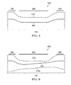
- graph 500 may represent the flow rate 425 of lubricant provided to gearbox 160 over time, in relation to a rotorcraft parameter 415 over time.
- rotorcraft parameter 415 may represent the rotational speed of mast 114 of rotorcraft 100.
- Rotorcraft 100 may initially be flying such that the rotational speed of mast 114 is at approximately one-hundred percent, in phase 530. After a reduction in lubricant pressure is detected, a pilot of rotorcraft 100 may reduce the rotational speed of mast 114 to approximately seventy percent, in cruise phase 540.
- rotorcraft 100 Once rotorcraft 100 is located in an area where rotorcraft 100 may land safely, the pilot of rotorcraft 100 may increase the rotational speed of mast 114, in phase 550, back to approximately one-hundred percent so that rotorcraft 100 may land.
- the flow rate 425 of lubricant to the gearboxes may be approximately six-hundred cubic centimeters per minute.
- the flow rate 425 of lubricant to gearbox 160 may be approximately four-hundred cubic centimeters per minute.
- flow rate 425 may vary depending on several factors. For example, flow rate 425 may vary depending on the weight of the rotorcraft, the design and size of the gearbox, operating conditions, and operator preferences. Therefore, FIGURE 5 is just one example and other ratios of flow rate 425 versus rotorcraft parameter 415 are contemplated.
- Teachings of certain embodiments recognize the capability to determine flow rate 425 by several different methods.
- One method may be to calculate flow rate 425 based on a specified ratio and the rotorcraft parameter 415.
- Another method may be to use a table of each rotorcraft parameter 415 values with corresponding flow rate 425 values.
- rotorcraft parameter 415 may be used by lubrication flow calculation unit 420 to determine flow rate 425.
- rotorcraft parameter 415 may represent the rotational speed of mast 114
- rotorcraft parameter 415a may represent the temperature of the lubricant in gearbox 160. Therefore, a combination of speed of mast 114 and temperature of lubricant in gearbox 160 may be used by lubrication flow calculation unit 420 to determine flow rate 425.
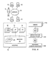
- lubrication flow calculation unit 420 may be implemented by one or more computers 10 communicating across one or more networks 30 and accessible by a user 5.
- An example of computer system 10 may include, but is not limited to, a flight control computer installed on-board an aircraft such as rotorcraft 100.
- elements of lubrication flow calculation unit 420 may be installed on-board an aircraft, off-board (such as at a ground facility), or a combination of the two.
- some elements of lubrication flow calculation unit 420 are installed on-board the aircraft whereas other elements of lubrication flow calculation unit 420 are installed off-board such that an on-board computer may include the capability to calculate flow rate 425 during flight as well as the capability to upload/download information to an off-board computer between flights.
- Computer system 10 may be used by lubrication flow calculation unit 420 to input the rotorcraft parameter 415 from one or more sensors 410, determine lubrication flow rate 425, and instruct secondary lubrication system 430 to adjust the flow rate 425 to gearbox 160.
- Users 5 may access lubrication flow calculation unit 420 through computer systems 10.
- Users 5 may include any individual, group of individuals, entity, machine, and/or mechanism that interacts with computer systems 10. Examples of users 5 include, but are not limited to, a pilot, service person, engineer, technician, contractor, agent, and/or employee.
- Users 5 may be associated with an organization.
- An organization may include any social arrangement that pursues collective goals.
- An example of an organization is a business.
- a business is an organization designed to provide goods or services, or both, to consumers, governmental entities, and/or other businesses.
- Computer system 10 may include processors 12, input/output devices 14, communications links 16, and memory 18. In other embodiments, computer system 10 may include more, less, or other components. Computer system 10 may be operable to perform one or more operations of various embodiments. Although the embodiment shown provides one example of computer system 10 that may be used with other embodiments, such other embodiments may utilize computers other than computer system 10. Additionally, embodiments may also employ multiple computer systems 10 or other computers networked together in one or more public and/or private computer networks, such as one or more networks 30.
- Processors 12 represent devices operable to execute logic contained within a medium. Examples of processor 12 include one or more microprocessors, one or more applications, and/or other logic. Computer system 10 may include one or multiple processors 12.
- Input/output devices 14 may include any device or interface operable to enable communication between computer system 10 and external components, including communication with a user or another system.
- Example input/output devices 14 may include, but are not limited to, a mouse, keyboard, display, and printer.
- Network interfaces 16 are operable to facilitate communication between computer system 10 and another element of a network, such as other computer systems 10.
- Network interfaces 16 may connect to any number and combination of wireline and/or wireless networks suitable for data transmission, including transmission of communications.
- Network interfaces 16 may, for example, communicate audio and/or video signals, messages, internet protocol packets, frame relay frames, asynchronous transfer mode cells, and/or other suitable data between network addresses.
- Network interfaces 16 connect to a computer network or a variety of other communicative platforms including, but not limited to, a public switched telephone network (PSTN); a public or private data network; one or more intranets; a local area network (LAN); a metropolitan area network (MAN); a wide area network (WAN); a wireline or wireless network; a local, regional, or global communication network; an optical network; a satellite network; a cellular network; an enterprise intranet; all or a portion of the Internet; other suitable network interfaces; or any combination of the preceding.
- PSTN public switched telephone network
- LAN local area network
- MAN metropolitan area network
- WAN wide area network
- wireline or wireless network a local, regional, or global communication network
- an optical network a satellite network
- a cellular network an enterprise intranet
- all or a portion of the Internet other suitable network interfaces; or any combination of the preceding.
- Memory 18 represents any suitable storage mechanism and may store any data for use by computer system 10.
- Memory 18 may comprise one or more tangible, computer-readable, and/or computer-executable storage medium.
- Examples of memory 18 include computer memory (for example, Random Access Memory (RAM) or Read Only Memory (ROM)), mass storage media (for example, a hard disk), removable storage media (for example, a Compact Disk (CD) or a Digital Video Disk (DVD)), database and/or network storage (for example, a server), and/or other computer-readable medium.
- memory 18 stores logic 20.
- Logic 20 facilitates operation of computer system 10.
- Logic 20 may include hardware, software, and/or other logic.
- Logic 20 may be encoded in one or more tangible, non-transitory media and may perform operations when executed by a computer.
- Logic 20 may include a computer program, software, computer executable instructions, and/or instructions capable of being executed by computer system 10.
- Example logic 20 may include any of the well-known OS2, UNIX, Mac-OS, Linux, and Windows Operating Systems or other operating systems.
- the operations of the embodiments may be performed by one or more computer readable media storing, embodied with, and/or encoded with a computer program and/or having a stored and/or an encoded computer program.
- Logic 20 may also be embedded within any other suitable medium without departing from the scope of the invention.
- Network 30 may represent any number and combination of wireline and/or wireless networks suitable for data transmission.
- Network 30 may, for example, communicate internet protocol packets, frame relay frames, asynchronous transfer mode cells, and/or other suitable data between network addresses.
- Network 30 may include a public or private data network; one or more intranets; a local area network (LAN); a metropolitan area network (MAN); a wide area network (WAN); a wireline or wireless network; a local, regional, or global communication network; an optical network; a satellite network; a cellular network; an enterprise intranet; all or a portion of the Internet; other suitable communication links; or any combination of the preceding.
- teachings of certain embodiments recognize that more or fewer networks may be used and that not all elements may communicate via a network.
- teachings of certain embodiments also recognize that communications over a network is one example of a mechanism for communicating between parties, and any suitable mechanism may be used.
Landscapes
- Engineering & Computer Science (AREA)
- General Engineering & Computer Science (AREA)
- Mechanical Engineering (AREA)
- Aviation & Aerospace Engineering (AREA)
- General Details Of Gearings (AREA)
- Testing Of Devices, Machine Parts, Or Other Structures Thereof (AREA)
Applications Claiming Priority (1)
| Application Number | Priority Date | Filing Date | Title |
|---|---|---|---|
| US14/693,334 US9683652B2 (en) | 2015-04-22 | 2015-04-22 | Method for the delivery of lubricant to a rotorcraft gearbox |
Publications (2)
| Publication Number | Publication Date |
|---|---|
| EP3085998A1 true EP3085998A1 (de) | 2016-10-26 |
| EP3085998B1 EP3085998B1 (de) | 2017-08-09 |
Family
ID=53284080
Family Applications (1)
| Application Number | Title | Priority Date | Filing Date |
|---|---|---|---|
| EP15170121.6A Active EP3085998B1 (de) | 2015-04-22 | 2015-06-01 | Verfahren zur verabreichung eines schmierstoffes an ein drehflüglergetriebe |
Country Status (2)
| Country | Link |
|---|---|
| US (1) | US9683652B2 (de) |
| EP (1) | EP3085998B1 (de) |
Cited By (1)
| Publication number | Priority date | Publication date | Assignee | Title |
|---|---|---|---|---|
| EP3447267A1 (de) * | 2017-08-23 | 2019-02-27 | Bell Helicopter Textron Inc. | Durch komponenten- oder reservoirdrehung druckbeaufschlagte zusatzschmierung |
Families Citing this family (13)
| Publication number | Priority date | Publication date | Assignee | Title |
|---|---|---|---|---|
| US9677663B2 (en) * | 2013-06-28 | 2017-06-13 | Sikorsky Aircraft Corporation | Gear geometry with fluid reservoir and fluid paths |
| US10677343B2 (en) * | 2015-02-18 | 2020-06-09 | Sikorsky Aircraft Corporation | Fluid distribution assembly having anti-clog inlet housing |
| GB2536916B (en) * | 2015-03-31 | 2018-09-26 | Skf Ab | Lubricating device with a control unit for operating the lubricating pump |
| US10786794B2 (en) | 2015-05-22 | 2020-09-29 | Digi-Star, Llc | Recording mixer rotation rate along with weight of feed and date and time |
| US9964966B1 (en) * | 2015-09-28 | 2018-05-08 | Amazon Technologies, Inc. | Controlling mechanical vibrations |
| US11162572B2 (en) * | 2016-09-23 | 2021-11-02 | Textron Innovations Inc. | Convective cooling of a pressurized gearbox |
| US10753536B2 (en) * | 2017-12-19 | 2020-08-25 | The United States Of America As Represented By The Secretary Of The Army | Detecting and predicting mechanical failure due to lubrication loss in machines and movable components |
| US11009116B2 (en) * | 2018-04-24 | 2021-05-18 | Bell Helicopter Textron Inc. | Passive oil system for planetary bearings |
| US10808826B2 (en) | 2018-06-15 | 2020-10-20 | Bell Helicopter Textron Inc. | Systems and methods for monitoring lubrication of a drive train |
| US11480245B2 (en) | 2018-11-27 | 2022-10-25 | Textron Innovations Inc. | Emergency lubrication system for tiltrotor aircraft |
| GB202015023D0 (en) * | 2020-09-23 | 2020-11-04 | Rolls Royce Plc | System and method for determining high oil consumption in gas turbine engine |
| US12078239B2 (en) | 2022-10-25 | 2024-09-03 | Lockheed Martin Corporation | Gearbox lubrication system for an aircraft |
| US12270337B1 (en) * | 2023-11-03 | 2025-04-08 | General Electric Company | Gas turbine engine oil flow control system |
Citations (4)
| Publication number | Priority date | Publication date | Assignee | Title |
|---|---|---|---|---|
| US20070261922A1 (en) * | 2006-01-05 | 2007-11-15 | Sikorsky Aircraft Corporation | Secondary lubrication system with injectable additive |
| US20110138817A1 (en) * | 2009-12-11 | 2011-06-16 | Eurocopter | Method of increasing the safety of a power plant, and a power plant suitable for implementing the method |
| US20120227820A1 (en) | 2009-11-16 | 2012-09-13 | Bell Gelicopter Textron Inc. | Emergency Subsystem for a Fluid System |
| EP2679491A1 (de) * | 2012-06-29 | 2014-01-01 | Bell Helicopter Textron Inc. | Flugzeuggetriebe-Schmiersystem und Verfahren zur Schmierung eines Flugzeuggetriebes |
Family Cites Families (12)
| Publication number | Priority date | Publication date | Assignee | Title |
|---|---|---|---|---|
| US5067454A (en) * | 1989-06-14 | 1991-11-26 | Avco Corporation | Self compensating flow control lubrication system |
| FR2658577A1 (fr) * | 1990-02-20 | 1991-08-23 | Aerospatiale | Dispositif de lubrification de secours pour reducteur notamment pour boite de transmission principale de giravion. |
| FR2683204B1 (fr) * | 1991-10-30 | 1997-04-25 | Aerospatiale | Systeme de sauvegarde d'un ensemble mecanique multiplicateur/reducteur, en particulier du type "boite de transmission" d'helicoptere, en cas de perte d'huile de lubrification. |
| FR2685758B1 (fr) * | 1991-12-26 | 1995-03-31 | Aerospatiale | Systeme de lubrification et de refroidissement de secours d'un multiplicateur/reducteur mecanique du type "boite de transmission" d'helicoptere en cas de defaillance du circuit de lubrification. |
| US5381874A (en) * | 1993-10-15 | 1995-01-17 | Caterpillar Inc. | Automatic lubrication control |
| US7017712B1 (en) * | 1997-03-19 | 2006-03-28 | Trico Mfg. Corp. | Apparatus and method for lubricant condition control and monitoring |
| JP2003088178A (ja) * | 2001-09-12 | 2003-03-20 | Sumitomo Heavy Ind Ltd | インバータ付きギヤモータ |
| US7506724B2 (en) * | 2004-07-23 | 2009-03-24 | Honeywell International Inc. | Active gas turbine lubrication system flow control |
| US7931124B2 (en) * | 2007-12-12 | 2011-04-26 | United Technologies Corporation | On-demand lubrication system and method for improved flow management and containment |
| US8746404B2 (en) * | 2008-07-30 | 2014-06-10 | United Technologies Corporation | Gas turbine engine systems and methods involving oil flow management |
| GB201209225D0 (en) * | 2012-05-22 | 2012-07-04 | Ionix Group Ltd | Sensor |
| US9316630B2 (en) * | 2013-11-08 | 2016-04-19 | Sikorsky Aircraft Corporation | Anti-clog and non-metallic debris detector for lubrication system inlet |
-
2015
- 2015-04-22 US US14/693,334 patent/US9683652B2/en active Active
- 2015-06-01 EP EP15170121.6A patent/EP3085998B1/de active Active
Patent Citations (4)
| Publication number | Priority date | Publication date | Assignee | Title |
|---|---|---|---|---|
| US20070261922A1 (en) * | 2006-01-05 | 2007-11-15 | Sikorsky Aircraft Corporation | Secondary lubrication system with injectable additive |
| US20120227820A1 (en) | 2009-11-16 | 2012-09-13 | Bell Gelicopter Textron Inc. | Emergency Subsystem for a Fluid System |
| US20110138817A1 (en) * | 2009-12-11 | 2011-06-16 | Eurocopter | Method of increasing the safety of a power plant, and a power plant suitable for implementing the method |
| EP2679491A1 (de) * | 2012-06-29 | 2014-01-01 | Bell Helicopter Textron Inc. | Flugzeuggetriebe-Schmiersystem und Verfahren zur Schmierung eines Flugzeuggetriebes |
Cited By (2)
| Publication number | Priority date | Publication date | Assignee | Title |
|---|---|---|---|---|
| EP3447267A1 (de) * | 2017-08-23 | 2019-02-27 | Bell Helicopter Textron Inc. | Durch komponenten- oder reservoirdrehung druckbeaufschlagte zusatzschmierung |
| US10697586B2 (en) | 2017-08-23 | 2020-06-30 | Bell Helicopter Textron Inc. | Supplemental lubrication pressurized by component or reservoir rotation |
Also Published As
| Publication number | Publication date |
|---|---|
| US9683652B2 (en) | 2017-06-20 |
| US20160311527A1 (en) | 2016-10-27 |
| EP3085998B1 (de) | 2017-08-09 |
Similar Documents
| Publication | Publication Date | Title |
|---|---|---|
| US9683652B2 (en) | Method for the delivery of lubricant to a rotorcraft gearbox | |
| US10443706B2 (en) | Gearbox lubrication system | |
| US10145464B2 (en) | Gearbox with passive lubrication system | |
| US10808826B2 (en) | Systems and methods for monitoring lubrication of a drive train | |
| EP2865595B1 (de) | Rotorbremsensteuerungssystem | |
| US8464980B2 (en) | Power plant, a helicopter including such a power plant, and a method implemented by said power plant | |
| US11713804B2 (en) | Passive oil system for planetary bearings | |
| US20200140069A1 (en) | Disconnecting a rotor | |
| EP2679491B1 (de) | Flugzeuggetriebe-Schmiersystem und Verfahren zur Schmierung eines Flugzeuggetriebes | |
| US10611496B2 (en) | Power allocation systems for aircraft | |
| US9399511B2 (en) | Rotorcraft fly-by-wire control laws | |
| US10940945B2 (en) | Rotorcraft anti-torque system | |
| US11306813B2 (en) | Passive planetary emergency lubrication system | |
| US12202599B2 (en) | Autonomous emergency lubrication of aircraft gearboxes | |
| EP3239046B1 (de) | Überwachung von mehreren komponenten durch ein einziges cockpitinstrument | |
| US12441466B2 (en) | System for testing aircraft emergency lubrication system | |
| US11077936B2 (en) | Fluid delivery device | |
| CA2867905C (en) | Rotor brake with integrated impeller | |
| EP4420977A1 (de) | System und verfahren zur überwachung des kupplungsverschleisses |
Legal Events
| Date | Code | Title | Description |
|---|---|---|---|
| PUAI | Public reference made under article 153(3) epc to a published international application that has entered the european phase |
Free format text: ORIGINAL CODE: 0009012 |
|
| 17P | Request for examination filed |
Effective date: 20150601 |
|
| AK | Designated contracting states |
Kind code of ref document: A1 Designated state(s): AL AT BE BG CH CY CZ DE DK EE ES FI FR GB GR HR HU IE IS IT LI LT LU LV MC MK MT NL NO PL PT RO RS SE SI SK SM TR |
|
| AX | Request for extension of the european patent |
Extension state: BA ME |
|
| GRAP | Despatch of communication of intention to grant a patent |
Free format text: ORIGINAL CODE: EPIDOSNIGR1 |
|
| INTG | Intention to grant announced |
Effective date: 20170405 |
|
| GRAS | Grant fee paid |
Free format text: ORIGINAL CODE: EPIDOSNIGR3 |
|
| GRAA | (expected) grant |
Free format text: ORIGINAL CODE: 0009210 |
|
| AK | Designated contracting states |
Kind code of ref document: B1 Designated state(s): AL AT BE BG CH CY CZ DE DK EE ES FI FR GB GR HR HU IE IS IT LI LT LU LV MC MK MT NL NO PL PT RO RS SE SI SK SM TR |
|
| REG | Reference to a national code |
Ref country code: GB Ref legal event code: FG4D |
|
| REG | Reference to a national code |
Ref country code: CH Ref legal event code: EP Ref country code: AT Ref legal event code: REF Ref document number: 917214 Country of ref document: AT Kind code of ref document: T Effective date: 20170815 |
|
| REG | Reference to a national code |
Ref country code: IE Ref legal event code: FG4D |
|
| REG | Reference to a national code |
Ref country code: DE Ref legal event code: R096 Ref document number: 602015003948 Country of ref document: DE |
|
| REG | Reference to a national code |
Ref country code: NL Ref legal event code: MP Effective date: 20170809 |
|
| REG | Reference to a national code |
Ref country code: LT Ref legal event code: MG4D |
|
| REG | Reference to a national code |
Ref country code: AT Ref legal event code: MK05 Ref document number: 917214 Country of ref document: AT Kind code of ref document: T Effective date: 20170809 |
|
| PG25 | Lapsed in a contracting state [announced via postgrant information from national office to epo] |
Ref country code: SE Free format text: LAPSE BECAUSE OF FAILURE TO SUBMIT A TRANSLATION OF THE DESCRIPTION OR TO PAY THE FEE WITHIN THE PRESCRIBED TIME-LIMIT Effective date: 20170809 Ref country code: FI Free format text: LAPSE BECAUSE OF FAILURE TO SUBMIT A TRANSLATION OF THE DESCRIPTION OR TO PAY THE FEE WITHIN THE PRESCRIBED TIME-LIMIT Effective date: 20170809 Ref country code: HR Free format text: LAPSE BECAUSE OF FAILURE TO SUBMIT A TRANSLATION OF THE DESCRIPTION OR TO PAY THE FEE WITHIN THE PRESCRIBED TIME-LIMIT Effective date: 20170809 Ref country code: NO Free format text: LAPSE BECAUSE OF FAILURE TO SUBMIT A TRANSLATION OF THE DESCRIPTION OR TO PAY THE FEE WITHIN THE PRESCRIBED TIME-LIMIT Effective date: 20171109 Ref country code: AT Free format text: LAPSE BECAUSE OF FAILURE TO SUBMIT A TRANSLATION OF THE DESCRIPTION OR TO PAY THE FEE WITHIN THE PRESCRIBED TIME-LIMIT Effective date: 20170809 Ref country code: LT Free format text: LAPSE BECAUSE OF FAILURE TO SUBMIT A TRANSLATION OF THE DESCRIPTION OR TO PAY THE FEE WITHIN THE PRESCRIBED TIME-LIMIT Effective date: 20170809 Ref country code: NL Free format text: LAPSE BECAUSE OF FAILURE TO SUBMIT A TRANSLATION OF THE DESCRIPTION OR TO PAY THE FEE WITHIN THE PRESCRIBED TIME-LIMIT Effective date: 20170809 |
|
| PG25 | Lapsed in a contracting state [announced via postgrant information from national office to epo] |
Ref country code: ES Free format text: LAPSE BECAUSE OF FAILURE TO SUBMIT A TRANSLATION OF THE DESCRIPTION OR TO PAY THE FEE WITHIN THE PRESCRIBED TIME-LIMIT Effective date: 20170809 Ref country code: RS Free format text: LAPSE BECAUSE OF FAILURE TO SUBMIT A TRANSLATION OF THE DESCRIPTION OR TO PAY THE FEE WITHIN THE PRESCRIBED TIME-LIMIT Effective date: 20170809 Ref country code: IS Free format text: LAPSE BECAUSE OF FAILURE TO SUBMIT A TRANSLATION OF THE DESCRIPTION OR TO PAY THE FEE WITHIN THE PRESCRIBED TIME-LIMIT Effective date: 20171209 Ref country code: LV Free format text: LAPSE BECAUSE OF FAILURE TO SUBMIT A TRANSLATION OF THE DESCRIPTION OR TO PAY THE FEE WITHIN THE PRESCRIBED TIME-LIMIT Effective date: 20170809 Ref country code: PL Free format text: LAPSE BECAUSE OF FAILURE TO SUBMIT A TRANSLATION OF THE DESCRIPTION OR TO PAY THE FEE WITHIN THE PRESCRIBED TIME-LIMIT Effective date: 20170809 Ref country code: GR Free format text: LAPSE BECAUSE OF FAILURE TO SUBMIT A TRANSLATION OF THE DESCRIPTION OR TO PAY THE FEE WITHIN THE PRESCRIBED TIME-LIMIT Effective date: 20171110 Ref country code: BG Free format text: LAPSE BECAUSE OF FAILURE TO SUBMIT A TRANSLATION OF THE DESCRIPTION OR TO PAY THE FEE WITHIN THE PRESCRIBED TIME-LIMIT Effective date: 20171109 |
|
| PG25 | Lapsed in a contracting state [announced via postgrant information from national office to epo] |
Ref country code: CZ Free format text: LAPSE BECAUSE OF FAILURE TO SUBMIT A TRANSLATION OF THE DESCRIPTION OR TO PAY THE FEE WITHIN THE PRESCRIBED TIME-LIMIT Effective date: 20170809 Ref country code: DK Free format text: LAPSE BECAUSE OF FAILURE TO SUBMIT A TRANSLATION OF THE DESCRIPTION OR TO PAY THE FEE WITHIN THE PRESCRIBED TIME-LIMIT Effective date: 20170809 |
|
| REG | Reference to a national code |
Ref country code: DE Ref legal event code: R097 Ref document number: 602015003948 Country of ref document: DE |
|
| PG25 | Lapsed in a contracting state [announced via postgrant information from national office to epo] |
Ref country code: EE Free format text: LAPSE BECAUSE OF FAILURE TO SUBMIT A TRANSLATION OF THE DESCRIPTION OR TO PAY THE FEE WITHIN THE PRESCRIBED TIME-LIMIT Effective date: 20170809 Ref country code: SM Free format text: LAPSE BECAUSE OF FAILURE TO SUBMIT A TRANSLATION OF THE DESCRIPTION OR TO PAY THE FEE WITHIN THE PRESCRIBED TIME-LIMIT Effective date: 20170809 Ref country code: SK Free format text: LAPSE BECAUSE OF FAILURE TO SUBMIT A TRANSLATION OF THE DESCRIPTION OR TO PAY THE FEE WITHIN THE PRESCRIBED TIME-LIMIT Effective date: 20170809 |
|
| PLBE | No opposition filed within time limit |
Free format text: ORIGINAL CODE: 0009261 |
|
| STAA | Information on the status of an ep patent application or granted ep patent |
Free format text: STATUS: NO OPPOSITION FILED WITHIN TIME LIMIT |
|
| REG | Reference to a national code |
Ref country code: FR Ref legal event code: PLFP Year of fee payment: 4 |
|
| 26N | No opposition filed |
Effective date: 20180511 |
|
| PG25 | Lapsed in a contracting state [announced via postgrant information from national office to epo] |
Ref country code: SI Free format text: LAPSE BECAUSE OF FAILURE TO SUBMIT A TRANSLATION OF THE DESCRIPTION OR TO PAY THE FEE WITHIN THE PRESCRIBED TIME-LIMIT Effective date: 20170809 |
|
| REG | Reference to a national code |
Ref country code: CH Ref legal event code: PL |
|
| REG | Reference to a national code |
Ref country code: BE Ref legal event code: MM Effective date: 20180630 |
|
| REG | Reference to a national code |
Ref country code: IE Ref legal event code: MM4A |
|
| PG25 | Lapsed in a contracting state [announced via postgrant information from national office to epo] |
Ref country code: MC Free format text: LAPSE BECAUSE OF FAILURE TO SUBMIT A TRANSLATION OF THE DESCRIPTION OR TO PAY THE FEE WITHIN THE PRESCRIBED TIME-LIMIT Effective date: 20170809 Ref country code: LU Free format text: LAPSE BECAUSE OF NON-PAYMENT OF DUE FEES Effective date: 20180601 |
|
| PG25 | Lapsed in a contracting state [announced via postgrant information from national office to epo] |
Ref country code: IE Free format text: LAPSE BECAUSE OF NON-PAYMENT OF DUE FEES Effective date: 20180601 Ref country code: LI Free format text: LAPSE BECAUSE OF NON-PAYMENT OF DUE FEES Effective date: 20180630 Ref country code: CH Free format text: LAPSE BECAUSE OF NON-PAYMENT OF DUE FEES Effective date: 20180630 |
|
| PG25 | Lapsed in a contracting state [announced via postgrant information from national office to epo] |
Ref country code: BE Free format text: LAPSE BECAUSE OF NON-PAYMENT OF DUE FEES Effective date: 20180630 |
|
| PG25 | Lapsed in a contracting state [announced via postgrant information from national office to epo] |
Ref country code: MT Free format text: LAPSE BECAUSE OF NON-PAYMENT OF DUE FEES Effective date: 20180601 |
|
| PG25 | Lapsed in a contracting state [announced via postgrant information from national office to epo] |
Ref country code: TR Free format text: LAPSE BECAUSE OF FAILURE TO SUBMIT A TRANSLATION OF THE DESCRIPTION OR TO PAY THE FEE WITHIN THE PRESCRIBED TIME-LIMIT Effective date: 20170809 |
|
| PG25 | Lapsed in a contracting state [announced via postgrant information from national office to epo] |
Ref country code: PT Free format text: LAPSE BECAUSE OF FAILURE TO SUBMIT A TRANSLATION OF THE DESCRIPTION OR TO PAY THE FEE WITHIN THE PRESCRIBED TIME-LIMIT Effective date: 20170809 |
|
| PG25 | Lapsed in a contracting state [announced via postgrant information from national office to epo] |
Ref country code: RO Free format text: LAPSE BECAUSE OF FAILURE TO SUBMIT A TRANSLATION OF THE DESCRIPTION OR TO PAY THE FEE WITHIN THE PRESCRIBED TIME-LIMIT Effective date: 20170809 Ref country code: MK Free format text: LAPSE BECAUSE OF NON-PAYMENT OF DUE FEES Effective date: 20170809 Ref country code: HU Free format text: LAPSE BECAUSE OF FAILURE TO SUBMIT A TRANSLATION OF THE DESCRIPTION OR TO PAY THE FEE WITHIN THE PRESCRIBED TIME-LIMIT; INVALID AB INITIO Effective date: 20150601 Ref country code: CY Free format text: LAPSE BECAUSE OF FAILURE TO SUBMIT A TRANSLATION OF THE DESCRIPTION OR TO PAY THE FEE WITHIN THE PRESCRIBED TIME-LIMIT Effective date: 20170809 |
|
| PG25 | Lapsed in a contracting state [announced via postgrant information from national office to epo] |
Ref country code: AL Free format text: LAPSE BECAUSE OF FAILURE TO SUBMIT A TRANSLATION OF THE DESCRIPTION OR TO PAY THE FEE WITHIN THE PRESCRIBED TIME-LIMIT Effective date: 20170809 |
|
| P01 | Opt-out of the competence of the unified patent court (upc) registered |
Effective date: 20230602 |
|
| PGFP | Annual fee paid to national office [announced via postgrant information from national office to epo] |
Ref country code: DE Payment date: 20250627 Year of fee payment: 11 |
|
| PGFP | Annual fee paid to national office [announced via postgrant information from national office to epo] |
Ref country code: GB Payment date: 20250627 Year of fee payment: 11 |
|
| PGFP | Annual fee paid to national office [announced via postgrant information from national office to epo] |
Ref country code: FR Payment date: 20250625 Year of fee payment: 11 |
|
| PGFP | Annual fee paid to national office [announced via postgrant information from national office to epo] |
Ref country code: IT Payment date: 20250619 Year of fee payment: 11 |