EP3085939A1 - Piston for engine - Google Patents
Piston for engine Download PDFInfo
- Publication number
- EP3085939A1 EP3085939A1 EP16164969.4A EP16164969A EP3085939A1 EP 3085939 A1 EP3085939 A1 EP 3085939A1 EP 16164969 A EP16164969 A EP 16164969A EP 3085939 A1 EP3085939 A1 EP 3085939A1
- Authority
- EP
- European Patent Office
- Prior art keywords
- resin coating
- piston
- coating film
- recess
- moving direction
- Prior art date
- Legal status (The legal status is an assumption and is not a legal conclusion. Google has not performed a legal analysis and makes no representation as to the accuracy of the status listed.)
- Granted
Links
- 239000011347 resin Substances 0.000 claims abstract description 110
- 229920005989 resin Polymers 0.000 claims abstract description 110
- 239000011248 coating agent Substances 0.000 claims abstract description 109
- 238000000576 coating method Methods 0.000 claims abstract description 109
- 239000010705 motor oil Substances 0.000 abstract description 14
- 239000000314 lubricant Substances 0.000 description 15
- 239000000446 fuel Substances 0.000 description 3
- 238000002485 combustion reaction Methods 0.000 description 2
- 238000007796 conventional method Methods 0.000 description 2
- 230000000694 effects Effects 0.000 description 2
- 229910000838 Al alloy Inorganic materials 0.000 description 1
- OKTJSMMVPCPJKN-UHFFFAOYSA-N Carbon Chemical compound [C] OKTJSMMVPCPJKN-UHFFFAOYSA-N 0.000 description 1
- 229910001018 Cast iron Inorganic materials 0.000 description 1
- XUIMIQQOPSSXEZ-UHFFFAOYSA-N Silicon Chemical compound [Si] XUIMIQQOPSSXEZ-UHFFFAOYSA-N 0.000 description 1
- 239000003822 epoxy resin Substances 0.000 description 1
- 229910002804 graphite Inorganic materials 0.000 description 1
- 239000010439 graphite Substances 0.000 description 1
- 229910003480 inorganic solid Inorganic materials 0.000 description 1
- 239000000463 material Substances 0.000 description 1
- 229910052751 metal Inorganic materials 0.000 description 1
- 239000002184 metal Substances 0.000 description 1
- 239000007769 metal material Substances 0.000 description 1
- 238000000034 method Methods 0.000 description 1
- 239000003921 oil Substances 0.000 description 1
- 239000005011 phenolic resin Substances 0.000 description 1
- 229920006122 polyamide resin Polymers 0.000 description 1
- 229920000647 polyepoxide Polymers 0.000 description 1
- 229920001721 polyimide Polymers 0.000 description 1
- 239000009719 polyimide resin Substances 0.000 description 1
- 239000010703 silicon Substances 0.000 description 1
- 229910052710 silicon Inorganic materials 0.000 description 1
- 229910000314 transition metal oxide Inorganic materials 0.000 description 1
Images


Classifications
-
- F—MECHANICAL ENGINEERING; LIGHTING; HEATING; WEAPONS; BLASTING
- F02—COMBUSTION ENGINES; HOT-GAS OR COMBUSTION-PRODUCT ENGINE PLANTS
- F02F—CYLINDERS, PISTONS OR CASINGS, FOR COMBUSTION ENGINES; ARRANGEMENTS OF SEALINGS IN COMBUSTION ENGINES
- F02F3/00—Pistons
- F02F3/10—Pistons having surface coverings
-
- F—MECHANICAL ENGINEERING; LIGHTING; HEATING; WEAPONS; BLASTING
- F02—COMBUSTION ENGINES; HOT-GAS OR COMBUSTION-PRODUCT ENGINE PLANTS
- F02F—CYLINDERS, PISTONS OR CASINGS, FOR COMBUSTION ENGINES; ARRANGEMENTS OF SEALINGS IN COMBUSTION ENGINES
- F02F3/00—Pistons
- F02F3/0084—Pistons the pistons being constructed from specific materials
-
- F—MECHANICAL ENGINEERING; LIGHTING; HEATING; WEAPONS; BLASTING
- F16—ENGINEERING ELEMENTS AND UNITS; GENERAL MEASURES FOR PRODUCING AND MAINTAINING EFFECTIVE FUNCTIONING OF MACHINES OR INSTALLATIONS; THERMAL INSULATION IN GENERAL
- F16J—PISTONS; CYLINDERS; SEALINGS
- F16J1/00—Pistons; Trunk pistons; Plungers
- F16J1/02—Bearing surfaces
-
- F—MECHANICAL ENGINEERING; LIGHTING; HEATING; WEAPONS; BLASTING
- F16—ENGINEERING ELEMENTS AND UNITS; GENERAL MEASURES FOR PRODUCING AND MAINTAINING EFFECTIVE FUNCTIONING OF MACHINES OR INSTALLATIONS; THERMAL INSULATION IN GENERAL
- F16J—PISTONS; CYLINDERS; SEALINGS
- F16J1/00—Pistons; Trunk pistons; Plungers
- F16J1/08—Constructional features providing for lubrication
-
- F—MECHANICAL ENGINEERING; LIGHTING; HEATING; WEAPONS; BLASTING
- F02—COMBUSTION ENGINES; HOT-GAS OR COMBUSTION-PRODUCT ENGINE PLANTS
- F02F—CYLINDERS, PISTONS OR CASINGS, FOR COMBUSTION ENGINES; ARRANGEMENTS OF SEALINGS IN COMBUSTION ENGINES
- F02F3/00—Pistons
-
- F—MECHANICAL ENGINEERING; LIGHTING; HEATING; WEAPONS; BLASTING
- F02—COMBUSTION ENGINES; HOT-GAS OR COMBUSTION-PRODUCT ENGINE PLANTS
- F02F—CYLINDERS, PISTONS OR CASINGS, FOR COMBUSTION ENGINES; ARRANGEMENTS OF SEALINGS IN COMBUSTION ENGINES
- F02F3/00—Pistons
- F02F3/02—Pistons having means for accommodating or controlling heat expansion
- F02F3/027—Pistons having means for accommodating or controlling heat expansion the skirt wall having cavities
-
- F—MECHANICAL ENGINEERING; LIGHTING; HEATING; WEAPONS; BLASTING
- F05—INDEXING SCHEMES RELATING TO ENGINES OR PUMPS IN VARIOUS SUBCLASSES OF CLASSES F01-F04
- F05C—INDEXING SCHEME RELATING TO MATERIALS, MATERIAL PROPERTIES OR MATERIAL CHARACTERISTICS FOR MACHINES, ENGINES OR PUMPS OTHER THAN NON-POSITIVE-DISPLACEMENT MACHINES OR ENGINES
- F05C2253/00—Other material characteristics; Treatment of material
- F05C2253/12—Coating
-
- F—MECHANICAL ENGINEERING; LIGHTING; HEATING; WEAPONS; BLASTING
- F05—INDEXING SCHEMES RELATING TO ENGINES OR PUMPS IN VARIOUS SUBCLASSES OF CLASSES F01-F04
- F05C—INDEXING SCHEME RELATING TO MATERIALS, MATERIAL PROPERTIES OR MATERIAL CHARACTERISTICS FOR MACHINES, ENGINES OR PUMPS OTHER THAN NON-POSITIVE-DISPLACEMENT MACHINES OR ENGINES
- F05C2253/00—Other material characteristics; Treatment of material
- F05C2253/20—Resin
Definitions
- the present invention relates to a piston for an engine, in particular, to a piston for an engine capable of improving supply of engine oil to a recess.
- a piston for an engine having a resin coating film 102 and a recess 103 on a surface of a skirt part 101 is known (for example, see Japanese Patent No. 4749399 ( FIG. 1 )).
- a profile of the skirt part 101 is optimized by the resin coating film 102, and there are obtained advantages of reducing slapping noise of the piston and friction of the skirt part 101 by engine oil stored in the recess 103.
- the recess 103 since the plurality of recesses 103 are discretely arranged in spots on the single resin coating film 102, the recess 103 is surrounded by the resin coating film 102 and therefore it is difficult to supply the engine oil to the recess 103. Thus, a sufficient amount of the engine oil is not held in the recess 103 and therefore the friction reducing function of the engine oil for the skirt part 101 is insufficient.
- An object of the present invention is to provide a piston for an engine capable of improving supply of engine oil to a recess based on further study of a piston on which a resin coating film is formed.
- a piston for an engine including a skirt part 1, and a plurality of resin coating films 2 formed on a surface of the skirt part 1, wherein the resin coating films 2 are arranged in a plurality of discrete spots on the surface of the skirt part 1, and a mesh-like groove 4 is formed by a recess 3 defined by the resin coating films 2 adjacent to each other and the surface of the skirt part 1 between the resin coating films 2 adjacent to each other, the recess 3 formed on the skirt part 1 between the resin coating films 2 adjacent to each other in a piston circumference direction is set to be adjacent to another resin coating film 2 in a piston moving direction, and an end part 2A of the another resin coating film 2 in the piston moving direction is formed in a concave shape when seen in a piston radius direction.
- the concave shape of the end part 2A of the another resin coating film 2 in the piston moving direction is set to a V-shape.
- a V-shape angle is set to a range of 120 degrees ⁇ 20 degrees.
- the concave shape of the end part 2A of the another resin coating film 2 in the piston moving direction is set to a curved shape.
- a length of the resin coating film 2 in the piston moving direction is set to be longer than a length of the resin coating film 2 in the piston circumference direction.
- an engine oil holding area can be provided over a wide area on the skirt part. Since the overall resin coating film is arranged in a plurality of discrete spots on the surface of the skirt part and the mesh-like groove is formed by a recess defined by the discrete resin coating films adjacent to each other and the surface of the skirt part between the resin coating films adjacent to each other, the engine oil holding area can be provided over the wide area on the skirt part.
- the end part of another resin coating film in the piston moving direction is formed in a concave shape when seen in a piston radius direction, a lubricant which has moved along the recess by inertia in accordance with a piston movement collides against the concave end part of the another resin coating film. Due to an angle of the concave shape, the lubricant does not move away in the circumference direction, but tends to return to the original recess by a bounce back movement.
- the piston for the engine capable of improving supply of the engine oil to the recess can be provided.
- Examples of the concave shape of the end part of the another resin coating film may include a V-shape according to the second aspect, and a curved shape according to the fourth aspect. Further, it is preferable to set a V-shape angle to a range of 120 degrees ⁇ 20 degrees according to the third aspect because the lubricant holding property is further improved. Further, it is preferable to set a shape of the resin coating film according to the fifth aspect such that a length of the resin coating film in the piston moving direction is longer than a length of the resin coating film in the piston circumference direction.
- a vertical type diesel engine and a piston thereof are formed such that a cylinder head 15 is assembled above a cylinder 14, a piston 12 is fitted into the cylinder 14, and a crank shaft 17 is interlockingly connected to the piston 12 via a con-rod 16.
- An intake valve 18, an exhaust valve 19, and a fuel injector 20 are mounted to the cylinder head 15.
- the overall resin coating film is formed by a plurality of resin coating films 2 that are arranged in a plurality of discrete spots on the surface of the skirt part 1, and a mesh-like groove 4 is formed by a recess 3 defined by the resin coating films 2, 2 adjacent to each other and the surface of the skirt part 1 between the resin coating films 2, 2 adjacent to each other.
- the mesh-like groove 4 is formed between the resin coating films 2, 2 adjacent to each other and a bottom of the mesh-like groove 4 is formed by a metal surface of the skirt part 1 which is not covered with the resin coating film 2.
- the plurality of resin coating films 2, each of which comprises a discrete spot, may be considered to define, together, an overall resin coating film.
- the resin coating film 2 and the recess 3 are formed at a thrust side 12a and an anti-thrust side 12b of the piston 12.
- the thrust side 12a refers to a side where the piston 12 is pressed against the cylinder 14 by a combustion pressure when the piston 12 is moved downward in a combustion process
- the anti-thrust side 12b refers to a side opposite to the thrust side 12a.
- a body of the piston 12 is made of a metal material such as cast iron or aluminum alloy.
- the resin coating film 2 is made of a resin material such as polyamide resin, epoxy resin, phenol resin, silicon resin, or polyimide resin.
- An inorganic solid lubricant such as transition metal oxide or graphite is contained in the resin coating film 2.
- the resin coating film 2 is formed in a substantially rectangular shape in which a length of the resin coating film 2 in a piston moving direction 6 is longer than a length of the resin coating film 2 in a piston circumference direction 8.
- both end parts 2A, 2A of the resin coating film 2 in its longitudinal direction are formed in a concave shape, in particular, in a V-shape having edge surfaces 2a, 2a.
- the resin coating film 2 and the recess 3 are provided adjacent to each other in the piston moving direction 6.
- the recess 3 formed on the skirt part between the resin coating films 2, 2 adjacent to each other in the piston circumference direction 8 of the skirt part 1 is set to be adjacent to another resin coating film 2 in the piston moving direction 6, and end parts 2A of the another resin coating film 2 in the piston moving direction 6 are formed in a concave shape when seen in the piston radius direction.
- the resin coating film 2 has a pair of vertical sides 2B, 2B along the piston moving direction 6, and the both end parts 2A, 2A (short sides). Each of the end parts 2A is formed in a V-shape by a pair of edge surfaces 2a, 2a.
- the resin coating film 2 is formed in a substantially rectangular shape (laid hand drum like shape) in which the vertical side 2B is apparently longer than the width of the resin coating film 2.
- a ratio of a length of the resin coating film 2 in the piston moving direction 6, a length of the resin coating film 2 in the piston circumference direction 8, the minimum distance between the resin coating films 2, 2 adjacent to each other in the piston moving direction 6, and a distance between the resin coating films 2, 2 adjacent to each other in the piston circumference direction 8 (a width of a groove portion 7) is set to 40 : 12 : 6 : 5, however the ratio is not limited to this.
- a resin coating film row 5 formed with a plurality of the resin coating films 2 that are arranged at a predetermined interval in the piston circumference direction 8 of the skirt part 1.
- a plurality of the resin coating film rows 5 are arranged in a zigzag manner in the piston moving direction 6 such that each of the resin coating film rows 5 is shifted by a half pitch in the piston circumference direction 8 with respect to the adjacent resin coating film row 5.
- both end openings 7a, 7b in the piston moving direction 6 of the groove portion 7 (recess 3) formed between the resin coating films 2, 2 adjacent to each other in the resin coating film row 5 are provided to face the resin coating film 2 in the adjacent resin coating film row 5 in a piston moving direction 6, in particular, to face the center part of the resin coating film 2 in the piston circumference direction 8.
- a narrow angle ⁇ formed by right and left edge surfaces 2a, 2a of the end part 2A of the resin coating film 2 is set to an angle of 120 degrees (alternatively, a range of 120 degrees ⁇ 20 degrees).
- an effect is obtained by setting the angle ⁇ to a range of 60 degrees ⁇ ⁇ ⁇ 180 degrees, but a better effect may be obtained by setting the angle ⁇ to a range of "120 degrees ⁇ 20 degrees".
- a lubricant which moves in the recess 3 or the groove portion 7 formed between the resin coating films 2, 2 adjacent to each other in the piston circumference direction 8 in accordance with the movement (up and down) of the piston 12, flows out of the opening 7a, collides against the end part 2A of the adjacent resin coating film 2 in the piston moving direction 6 to be received, and then the lubricant is bounced back by the pair of the edge surfaces 2a, 2a.
- a recess which is formed by the end parts 2A of the resin coating films 2 adjacent to each other and which extends in the piston circumference direction 8 in a zigzag manner, forms an oil storing groove 9 having an excellent lubricant holding property.
- the adjacent resin coating film in the piston moving direction preferably overlaps the end opening of the recess. It may completely overlap the end opening.
- the bounced-back lubricant collides with the end part 2A of the resin coating film 2 forming the groove portion 7 and is further bounced back, or flows back to the original groove portion 7, the lubricant holding property is improved. Further, the bounced-back lubricant tends to move onto the resin coating film 2 adjacent to the groove portion 7, and therefore a positive pressure is generated between the cylinder 14 and the piston 12. The positive pressure separates a sliding surface of the piston 12 from a cylinder wall and reduces a friction, and therefore fuel efficiency can be improved.
- a vertical direction (piston moving direction 6) passage of the lubricant can be formed by separately applying a texturing process to each area on a surface of the skirt part 1, and the lubricant can be effectively supplied to each part of the piston 12. Since the resin coating film rows 5, 5 adjacent to each other in the piston moving direction 6 are arranged in a zigzag manner by shifting the resin coating film rows 5 with respect to each other in the piston circumference direction 8, the lubricant can be efficiently supplied to the recess 3 by using a reciprocating movement of the piston 12.
- a length of a vertical side 2B of a resin coating film 2 is substantially half of a length of the vertical side 2B of the resin coating film 2 (see FIG. 2A and 2B ) according to the first embodiment.
- a concave shape of an end part 2A of a resin coating film 2 in a piston moving direction 6 is set to a curved shape, and the end part 2A has a curved edge surface 10.
- edge parts 11, which are formed in a convex curved shape when seen in a piston radius direction, are provided at both ends of the end part 2A in a width direction of the resin coating film 2.
- a concave shape of an end part 2A of a resin coating film 2 in a piston moving direction 6 may be formed by three surfaces including a bottom surface 13, and left and right inclined surfaces 21, 21.
- a concave shape of an end part 2A of a resin coating film 2 in a piston moving direction 6 may be formed by a V-shape bottom surface 22 and right and left convex parts 23, 23.
- a concave shape of an end part 2A of a resin coating film 2 in a piston moving direction 6 may include a single concave curved surface 24.
- the concave curved surface 24 may have various shapes such as a circular shape and an ellipse shape.
Landscapes
- Engineering & Computer Science (AREA)
- General Engineering & Computer Science (AREA)
- Chemical & Material Sciences (AREA)
- Combustion & Propulsion (AREA)
- Mechanical Engineering (AREA)
- Pistons, Piston Rings, And Cylinders (AREA)
Abstract
Description
- The present invention relates to a piston for an engine, in particular, to a piston for an engine capable of improving supply of engine oil to a recess.
- Conventionally, as shown in
FIG. 6 , a piston for an engine having aresin coating film 102 and arecess 103 on a surface of askirt part 101 is known (for example, seeJapanese Patent No. 4749399 FIG. 1 )). - According to this kind of piston, a profile of the
skirt part 101 is optimized by theresin coating film 102, and there are obtained advantages of reducing slapping noise of the piston and friction of theskirt part 101 by engine oil stored in therecess 103. - However, in the conventional technique, as shown in
FIG. 6 , since the plurality ofrecesses 103 are discretely arranged in spots on the singleresin coating film 102, a friction reducing function of the engine oil for the skirt part is insufficient. - In other words, as shown in
FIG. 6 , since the plurality ofrecesses 103 are discretely arranged in spots on the singleresin coating film 102, therecess 103 is surrounded by theresin coating film 102 and therefore it is difficult to supply the engine oil to therecess 103. Thus, a sufficient amount of the engine oil is not held in therecess 103 and therefore the friction reducing function of the engine oil for theskirt part 101 is insufficient. - An object of the present invention is to provide a piston for an engine capable of improving supply of engine oil to a recess based on further study of a piston on which a resin coating film is formed.
- In accordance with a first aspect of the invention, there is provided a piston for an engine including a skirt part 1, and a plurality of
resin coating films 2 formed on a surface of the skirt part 1, wherein theresin coating films 2 are arranged in a plurality of discrete spots on the surface of the skirt part 1, and a mesh-like groove 4 is formed by arecess 3 defined by theresin coating films 2 adjacent to each other and the surface of the skirt part 1 between theresin coating films 2 adjacent to each other, therecess 3 formed on the skirt part 1 between theresin coating films 2 adjacent to each other in a piston circumference direction is set to be adjacent to anotherresin coating film 2 in a piston moving direction, and anend part 2A of the anotherresin coating film 2 in the piston moving direction is formed in a concave shape when seen in a piston radius direction. - In accordance with a second aspect of the invention, in the piston for the engine according to the first aspect, the concave shape of the
end part 2A of the anotherresin coating film 2 in the piston moving direction is set to a V-shape. - In accordance with a third aspect of the invention, in the piston for the engine according to the second aspect, a V-shape angle is set to a range of 120 degrees ± 20 degrees.
- In accordance with a fourth aspect of the invention, in the piston for the engine according to the first aspect, the concave shape of the
end part 2A of the anotherresin coating film 2 in the piston moving direction is set to a curved shape. - In accordance with a fifth aspect of the invention, in the piston for the engine according to any one of the first to fourth aspects, a length of the
resin coating film 2 in the piston moving direction is set to be longer than a length of theresin coating film 2 in the piston circumference direction. - According to the first aspect of the invention, an engine oil holding area can be provided over a wide area on the skirt part. Since the overall resin coating film is arranged in a plurality of discrete spots on the surface of the skirt part and the mesh-like groove is formed by a recess defined by the discrete resin coating films adjacent to each other and the surface of the skirt part between the resin coating films adjacent to each other, the engine oil holding area can be provided over the wide area on the skirt part.
- Out of the recess, since the recess formed on the skirt part between the resin coating films adjacent to each other in the piston circumference direction is set to be adjacent to another resin coating film in the piston moving direction, the engine oil which flows out from both end openings of the recess by a reciprocating movement of the piston collides against the adjacent resin coating film in the piston moving direction and the engine oil is prevented from flowing out from the recess. Thus, an engine oil holding property of the mesh-like groove can be enhanced.
- In addition, since the end part of another resin coating film in the piston moving direction is formed in a concave shape when seen in a piston radius direction, a lubricant which has moved along the recess by inertia in accordance with a piston movement collides against the concave end part of the another resin coating film. Due to an angle of the concave shape, the lubricant does not move away in the circumference direction, but tends to return to the original recess by a bounce back movement.
- Accordingly, more lubricant is held on the surface of the piston, and therefore a friction reducing function can be enhanced and fuel efficiency can be improved. In this way, according to the further study of the piston on which the resin coating film is formed, the piston for the engine capable of improving supply of the engine oil to the recess can be provided.
- Examples of the concave shape of the end part of the another resin coating film may include a V-shape according to the second aspect, and a curved shape according to the fourth aspect. Further, it is preferable to set a V-shape angle to a range of 120 degrees ± 20 degrees according to the third aspect because the lubricant holding property is further improved. Further, it is preferable to set a shape of the resin coating film according to the fifth aspect such that a length of the resin coating film in the piston moving direction is longer than a length of the resin coating film in the piston circumference direction.
-
-
FIG. 1 is a vertical cross-sectional view of a piston fitted into a cylinder; -
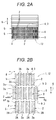
FIG. 2A is a side view of the piston, andFIG. 2B illustrates a coating pattern of a resin coating film; -
FIG. 3A is a cross-sectional view taken along line A-A inFIG. 2B , andFIG. 3B illustrates a lubricant holding function of the resin coating film and a recess; -
FIG. 4A illustrates a main part of a resin coating film and a recess according to a second embodiment, andFIG. 4B illustrates a main part of a resin coating film and a recess according to a third embodiment; -
FIG. 5A illustrates a main part of a resin coating film and a recess according to a fourth embodiment,FIG. 5B illustrates a main part of a resin coating film and a recess according to a fifth embodiment, andFIG. 5C illustrates a main part of a resin coating film and a recess according to a sixth embodiment; and -
FIG. 6 is a side view of a piston for an engine according to a conventional technique. - Hereinafter, embodiments of a piston according to the present invention will be described with reference to the drawings by using a piston for a vertical type diesel engine.
- As shown in
FIG. 1 , a vertical type diesel engine and a piston thereof are formed such that acylinder head 15 is assembled above acylinder 14, apiston 12 is fitted into thecylinder 14, and acrank shaft 17 is interlockingly connected to thepiston 12 via a con-rod 16. - An
intake valve 18, anexhaust valve 19, and afuel injector 20 are mounted to thecylinder head 15. - As shown in
FIGS. 1 ,2A, and 2B , in thepiston 12 for the engine having an overall resin coating film provided on a surface of a skirt part 1, the overall resin coating film is formed by a plurality ofresin coating films 2 that are arranged in a plurality of discrete spots on the surface of the skirt part 1, and a mesh-like groove 4 is formed by arecess 3 defined by theresin coating films resin coating films resin coating films resin coating film 2. - The plurality of
resin coating films 2, each of which comprises a discrete spot, may be considered to define, together, an overall resin coating film. - The
resin coating film 2 and therecess 3 are formed at athrust side 12a and ananti-thrust side 12b of thepiston 12. Thethrust side 12a refers to a side where thepiston 12 is pressed against thecylinder 14 by a combustion pressure when thepiston 12 is moved downward in a combustion process, and theanti-thrust side 12b refers to a side opposite to thethrust side 12a. A body of thepiston 12 is made of a metal material such as cast iron or aluminum alloy. Theresin coating film 2 is made of a resin material such as polyamide resin, epoxy resin, phenol resin, silicon resin, or polyimide resin. An inorganic solid lubricant such as transition metal oxide or graphite is contained in theresin coating film 2. - The
resin coating film 2 is formed in a substantially rectangular shape in which a length of theresin coating film 2 in apiston moving direction 6 is longer than a length of theresin coating film 2 in apiston circumference direction 8. When seen in a piston radius direction, bothend parts resin coating film 2 in its longitudinal direction are formed in a concave shape, in particular, in a V-shape havingedge surfaces resin coating film 2 and therecess 3 are provided adjacent to each other in thepiston moving direction 6. - That is, the
recess 3 formed on the skirt part between theresin coating films piston circumference direction 8 of the skirt part 1 is set to be adjacent to anotherresin coating film 2 in thepiston moving direction 6, andend parts 2A of the anotherresin coating film 2 in thepiston moving direction 6 are formed in a concave shape when seen in the piston radius direction. - As shown in
FIGS. 2A, 2B ,3A, and 3B , theresin coating film 2 has a pair ofvertical sides piston moving direction 6, and the bothend parts end parts 2A is formed in a V-shape by a pair ofedge surfaces resin coating film 2 is formed in a substantially rectangular shape (laid hand drum like shape) in which thevertical side 2B is apparently longer than the width of theresin coating film 2. - In
FIG. 2B , a ratio of a length of theresin coating film 2 in thepiston moving direction 6, a length of theresin coating film 2 in thepiston circumference direction 8, the minimum distance between theresin coating films piston moving direction 6, and a distance between theresin coating films - Further, as shown in
FIGS. 1 ,2A and 2B , there is provided a resincoating film row 5 formed with a plurality of theresin coating films 2 that are arranged at a predetermined interval in thepiston circumference direction 8 of the skirt part 1. A plurality of the resincoating film rows 5 are arranged in a zigzag manner in thepiston moving direction 6 such that each of the resincoating film rows 5 is shifted by a half pitch in thepiston circumference direction 8 with respect to the adjacent resincoating film row 5. Accordingly, bothend openings piston moving direction 6 of the groove portion 7 (recess 3) formed between theresin coating films coating film row 5 are provided to face theresin coating film 2 in the adjacent resincoating film row 5 in apiston moving direction 6, in particular, to face the center part of theresin coating film 2 in thepiston circumference direction 8. - Further, as shown in
FIGS. 2A and 2B , in thepiston 12 according to the first embodiment, a narrow angle θ formed by right and leftedge surfaces end part 2A of theresin coating film 2 is set to an angle of 120 degrees (alternatively, a range of 120 degrees ± 20 degrees). Here, an effect is obtained by setting the angle θ to a range of 60 degrees ≤ θ < 180 degrees, but a better effect may be obtained by setting the angle θ to a range of "120 degrees ± 20 degrees". - As shown in
FIG. 3B , a lubricant, which moves in therecess 3 or thegroove portion 7 formed between theresin coating films piston circumference direction 8 in accordance with the movement (up and down) of thepiston 12, flows out of theopening 7a, collides against theend part 2A of the adjacentresin coating film 2 in thepiston moving direction 6 to be received, and then the lubricant is bounced back by the pair of the edge surfaces 2a, 2a. - That is, a recess, which is formed by the
end parts 2A of theresin coating films 2 adjacent to each other and which extends in thepiston circumference direction 8 in a zigzag manner, forms anoil storing groove 9 having an excellent lubricant holding property. - The adjacent resin coating film in the piston moving direction preferably overlaps the end opening of the recess. It may completely overlap the end opening.
- Since the bounced-back lubricant collides with the
end part 2A of theresin coating film 2 forming thegroove portion 7 and is further bounced back, or flows back to theoriginal groove portion 7, the lubricant holding property is improved. Further, the bounced-back lubricant tends to move onto theresin coating film 2 adjacent to thegroove portion 7, and therefore a positive pressure is generated between thecylinder 14 and thepiston 12. The positive pressure separates a sliding surface of thepiston 12 from a cylinder wall and reduces a friction, and therefore fuel efficiency can be improved. - A vertical direction (piston moving direction 6) passage of the lubricant can be formed by separately applying a texturing process to each area on a surface of the skirt part 1, and the lubricant can be effectively supplied to each part of the
piston 12. Since the resincoating film rows piston moving direction 6 are arranged in a zigzag manner by shifting the resincoating film rows 5 with respect to each other in thepiston circumference direction 8, the lubricant can be efficiently supplied to therecess 3 by using a reciprocating movement of thepiston 12. - As shown in
FIG. 4A , in apiston 12 according to a second embodiment, a length of avertical side 2B of aresin coating film 2 is substantially half of a length of thevertical side 2B of the resin coating film 2 (seeFIG. 2A and 2B ) according to the first embodiment. With such a configuration, there is formed a mesh-like groove 4 with a smaller mesh size compared to that of the mesh-like groove 4 in the first embodiment. - As shown in
FIG. 4B , in apiston 12 according to a third embodiment, a concave shape of anend part 2A of aresin coating film 2 in apiston moving direction 6 is set to a curved shape, and theend part 2A has acurved edge surface 10. In this case,edge parts 11, which are formed in a convex curved shape when seen in a piston radius direction, are provided at both ends of theend part 2A in a width direction of theresin coating film 2. - As shown in
FIG. 5A , in apiston 12 according to a fourth embodiment, a concave shape of anend part 2A of aresin coating film 2 in apiston moving direction 6 may be formed by three surfaces including abottom surface 13, and left and rightinclined surfaces - As shown in
FIG. 5B , in apiston 12 according to a fifth embodiment, a concave shape of anend part 2A of aresin coating film 2 in apiston moving direction 6 may be formed by a V-shape bottom surface 22 and right and leftconvex parts - As shown in
FIG. 5C , in apiston 12 according to a sixth embodiment, a concave shape of anend part 2A of aresin coating film 2 in apiston moving direction 6 may include a single concavecurved surface 24. In this case, the concavecurved surface 24 may have various shapes such as a circular shape and an ellipse shape.
Claims (5)
- A piston for an engine comprising:a skirt part; anda plurality of resin coating films formed on a surface of the skirt part,wherein the resin coating films are arranged in a plurality of discrete spots on the surface of the skirt part, and a mesh-like groove is formed by a recess defined by the resin coating films adjacent to each other and the surface of the skirt part between the resin coating films,the recess formed on the skirt part between the resin coating films adjacent to each other in a piston circumference direction is set to be adjacent to another resin coating film in a piston moving direction, andan end part of the another resin coating film in the piston moving direction is formed in a concave shape when seen in a piston radius direction.
- The piston for the engine according to claim 1, wherein the concave shape of the end part of the another resin coating film in the piston moving direction is set to a V-shape.
- The piston for the engine according to claim 2, wherein a V-shape angle is set to a range of 120 degrees ± 20 degrees.
- The piston for the engine according to claim 1, wherein the concave shape of the end part of the another resin coating film in the piston moving direction is set to a curved shape.
- The piston for the engine according to any one of claims 1 to 4, wherein a length of the resin coating film in the piston moving direction is set to be longer than a length of the resin coating film in the piston circumference direction.
Applications Claiming Priority (1)
| Application Number | Priority Date | Filing Date | Title |
|---|---|---|---|
| JP2015087827A JP6401104B2 (en) | 2015-04-22 | 2015-04-22 | Engine pistons |
Publications (2)
| Publication Number | Publication Date |
|---|---|
| EP3085939A1 true EP3085939A1 (en) | 2016-10-26 |
| EP3085939B1 EP3085939B1 (en) | 2024-03-06 |
Family
ID=55755378
Family Applications (1)
| Application Number | Title | Priority Date | Filing Date |
|---|---|---|---|
| EP16164969.4A Active EP3085939B1 (en) | 2015-04-22 | 2016-04-12 | Piston for engine |
Country Status (4)
| Country | Link |
|---|---|
| US (1) | US10018147B2 (en) |
| EP (1) | EP3085939B1 (en) |
| JP (1) | JP6401104B2 (en) |
| CN (1) | CN106065826B (en) |
Cited By (1)
| Publication number | Priority date | Publication date | Assignee | Title |
|---|---|---|---|---|
| FR3094044A1 (en) * | 2019-03-21 | 2020-09-25 | Psa Automobiles Sa | INTERNAL COMBUSTION ENGINE PISTON |
Families Citing this family (4)
| Publication number | Priority date | Publication date | Assignee | Title |
|---|---|---|---|---|
| JP6443759B2 (en) * | 2015-05-25 | 2018-12-26 | スズキ株式会社 | Piston of internal combustion engine |
| JP6587978B2 (en) * | 2016-06-01 | 2019-10-09 | 株式会社クボタ | Engine pistons |
| DE102019219445A1 (en) * | 2019-12-12 | 2021-06-17 | Federal-Mogul Nürnberg GmbH | Piston and method of making the same |
| JP2021102928A (en) * | 2019-12-24 | 2021-07-15 | トヨタ自動車株式会社 | piston |
Citations (6)
| Publication number | Priority date | Publication date | Assignee | Title |
|---|---|---|---|---|
| JP2004137955A (en) * | 2002-10-17 | 2004-05-13 | Ntn Corp | Piston for internal combustion engine |
| US20050087166A1 (en) * | 2003-10-23 | 2005-04-28 | Wolfgang Rein | Piston having a patterned coating and method of applying same |
| JP2005320934A (en) * | 2004-05-11 | 2005-11-17 | Toyo Drilube Co Ltd | Reciprocatingly moving member |
| JP4749399B2 (en) | 2007-08-24 | 2011-08-17 | 本田技研工業株式会社 | Piston of internal combustion engine |
| US20140158081A1 (en) * | 2011-08-09 | 2014-06-12 | Suzuki Motor Corporation | Piston for internal combustion engine |
| JP2014234739A (en) * | 2013-05-31 | 2014-12-15 | 株式会社クボタ | Piston of engine |
Family Cites Families (5)
| Publication number | Priority date | Publication date | Assignee | Title |
|---|---|---|---|---|
| JP2529001Y2 (en) * | 1990-09-27 | 1997-03-12 | アイシン精機株式会社 | Piston for internal combustion engine |
| US6675761B2 (en) * | 2002-01-30 | 2004-01-13 | Caterpillar Inc | Ring band for a piston |
| DE10244511A1 (en) * | 2002-09-25 | 2004-04-15 | Mahle Gmbh | Multi-part cooled piston for an internal combustion engine |
| US7406941B2 (en) * | 2004-07-21 | 2008-08-05 | Federal - Mogul World Wide, Inc. | One piece cast steel monobloc piston |
| US20060086325A1 (en) * | 2004-10-25 | 2006-04-27 | Ipd, Inc. | Two piece cast ferrous crown piston for internal combustion engine |
-
2015
- 2015-04-22 JP JP2015087827A patent/JP6401104B2/en active Active
-
2016
- 2016-04-12 EP EP16164969.4A patent/EP3085939B1/en active Active
- 2016-04-15 CN CN201610235695.0A patent/CN106065826B/en active Active
- 2016-04-21 US US15/134,470 patent/US10018147B2/en active Active
Patent Citations (6)
| Publication number | Priority date | Publication date | Assignee | Title |
|---|---|---|---|---|
| JP2004137955A (en) * | 2002-10-17 | 2004-05-13 | Ntn Corp | Piston for internal combustion engine |
| US20050087166A1 (en) * | 2003-10-23 | 2005-04-28 | Wolfgang Rein | Piston having a patterned coating and method of applying same |
| JP2005320934A (en) * | 2004-05-11 | 2005-11-17 | Toyo Drilube Co Ltd | Reciprocatingly moving member |
| JP4749399B2 (en) | 2007-08-24 | 2011-08-17 | 本田技研工業株式会社 | Piston of internal combustion engine |
| US20140158081A1 (en) * | 2011-08-09 | 2014-06-12 | Suzuki Motor Corporation | Piston for internal combustion engine |
| JP2014234739A (en) * | 2013-05-31 | 2014-12-15 | 株式会社クボタ | Piston of engine |
Cited By (1)
| Publication number | Priority date | Publication date | Assignee | Title |
|---|---|---|---|---|
| FR3094044A1 (en) * | 2019-03-21 | 2020-09-25 | Psa Automobiles Sa | INTERNAL COMBUSTION ENGINE PISTON |
Also Published As
| Publication number | Publication date |
|---|---|
| EP3085939B1 (en) | 2024-03-06 |
| US10018147B2 (en) | 2018-07-10 |
| CN106065826A (en) | 2016-11-02 |
| US20160312739A1 (en) | 2016-10-27 |
| JP2016205236A (en) | 2016-12-08 |
| CN106065826B (en) | 2020-04-03 |
| JP6401104B2 (en) | 2018-10-03 |
Similar Documents
| Publication | Publication Date | Title |
|---|---|---|
| EP3085939B1 (en) | Piston for engine | |
| CN107448319B (en) | Piston of engine | |
| EP3270012B1 (en) | Side rail | |
| EP1719901A1 (en) | Piston device for internal combustion engine | |
| US7305960B2 (en) | Piston for an internal combustion engine | |
| EP1818530A1 (en) | Lubrication device for cylinder inner wall in two-stroke cycle internal combustion engine | |
| US9121341B2 (en) | Dual link internal combustion engine | |
| EP1840419A1 (en) | Piston with surface finishing | |
| JP6259585B2 (en) | Piston sliding part lubrication structure | |
| KR20170007237A (en) | Piston ring comprising a groove in the circumferential direction | |
| JP6490440B2 (en) | Monoblock engine cylinder structure | |
| JP6587980B2 (en) | Engine pistons | |
| JP6615742B2 (en) | Engine pistons | |
| CN114829759A (en) | Piston and method for producing a piston | |
| JP6579027B2 (en) | Cylinder bore wall of internal combustion engine | |
| JP6587979B2 (en) | Engine pistons | |
| US9850847B2 (en) | Piston for internal combustion engine | |
| JP2006112360A (en) | Piston device | |
| JP2020002821A (en) | Piston for engine | |
| JP6366807B2 (en) | Piston sliding part lubrication structure | |
| JP6860328B2 (en) | Pressure ring for internal combustion engine piston | |
| US20210189995A1 (en) | Piston | |
| KR20180070778A (en) | Surface pattern of piston skirt | |
| JP2014009620A (en) | Piston ring for internal combustion engine | |
| KR20200097168A (en) | Oil ring for internal combustion engine and piston assembly comprising the same |
Legal Events
| Date | Code | Title | Description |
|---|---|---|---|
| PUAI | Public reference made under article 153(3) epc to a published international application that has entered the european phase |
Free format text: ORIGINAL CODE: 0009012 |
|
| AK | Designated contracting states |
Kind code of ref document: A1 Designated state(s): AL AT BE BG CH CY CZ DE DK EE ES FI FR GB GR HR HU IE IS IT LI LT LU LV MC MK MT NL NO PL PT RO RS SE SI SK SM TR |
|
| AX | Request for extension of the european patent |
Extension state: BA ME |
|
| 17P | Request for examination filed |
Effective date: 20170426 |
|
| RBV | Designated contracting states (corrected) |
Designated state(s): AL AT BE BG CH CY CZ DE DK EE ES FI FR GB GR HR HU IE IS IT LI LT LU LV MC MK MT NL NO PL PT RO RS SE SI SK SM TR |
|
| STAA | Information on the status of an ep patent application or granted ep patent |
Free format text: STATUS: REQUEST FOR EXAMINATION WAS MADE |
|
| STAA | Information on the status of an ep patent application or granted ep patent |
Free format text: STATUS: EXAMINATION IS IN PROGRESS |
|
| 17Q | First examination report despatched |
Effective date: 20190124 |
|
| STAA | Information on the status of an ep patent application or granted ep patent |
Free format text: STATUS: EXAMINATION IS IN PROGRESS |
|
| STAA | Information on the status of an ep patent application or granted ep patent |
Free format text: STATUS: EXAMINATION IS IN PROGRESS |
|
| GRAP | Despatch of communication of intention to grant a patent |
Free format text: ORIGINAL CODE: EPIDOSNIGR1 |
|
| STAA | Information on the status of an ep patent application or granted ep patent |
Free format text: STATUS: GRANT OF PATENT IS INTENDED |
|
| INTG | Intention to grant announced |
Effective date: 20231214 |
|
| GRAS | Grant fee paid |
Free format text: ORIGINAL CODE: EPIDOSNIGR3 |
|
| GRAA | (expected) grant |
Free format text: ORIGINAL CODE: 0009210 |
|
| STAA | Information on the status of an ep patent application or granted ep patent |
Free format text: STATUS: THE PATENT HAS BEEN GRANTED |
|
| AK | Designated contracting states |
Kind code of ref document: B1 Designated state(s): AL AT BE BG CH CY CZ DE DK EE ES FI FR GB GR HR HU IE IS IT LI LT LU LV MC MK MT NL NO PL PT RO RS SE SI SK SM TR |
|
| REG | Reference to a national code |
Ref country code: GB Ref legal event code: FG4D |
|
| REG | Reference to a national code |
Ref country code: CH Ref legal event code: EP |
|
| REG | Reference to a national code |
Ref country code: DE Ref legal event code: R096 Ref document number: 602016086121 Country of ref document: DE |
|
| REG | Reference to a national code |
Ref country code: IE Ref legal event code: FG4D |
|
| PGFP | Annual fee paid to national office [announced via postgrant information from national office to epo] |
Ref country code: GB Payment date: 20240319 Year of fee payment: 9 |