EP3085903A1 - Adjusting valve drive mechanism and steam turbine - Google Patents
Adjusting valve drive mechanism and steam turbine Download PDFInfo
- Publication number
- EP3085903A1 EP3085903A1 EP14871770.5A EP14871770A EP3085903A1 EP 3085903 A1 EP3085903 A1 EP 3085903A1 EP 14871770 A EP14871770 A EP 14871770A EP 3085903 A1 EP3085903 A1 EP 3085903A1
- Authority
- EP
- European Patent Office
- Prior art keywords
- adjusting valve
- drive mechanism
- spur gear
- valve drive
- steam
- Prior art date
- Legal status (The legal status is an assumption and is not a legal conclusion. Google has not performed a legal analysis and makes no representation as to the accuracy of the status listed.)
- Withdrawn
Links
Images



Classifications
-
- F—MECHANICAL ENGINEERING; LIGHTING; HEATING; WEAPONS; BLASTING
- F01—MACHINES OR ENGINES IN GENERAL; ENGINE PLANTS IN GENERAL; STEAM ENGINES
- F01K—STEAM ENGINE PLANTS; STEAM ACCUMULATORS; ENGINE PLANTS NOT OTHERWISE PROVIDED FOR; ENGINES USING SPECIAL WORKING FLUIDS OR CYCLES
- F01K13/00—General layout or general methods of operation of complete plants
- F01K13/02—Controlling, e.g. stopping or starting
-
- F—MECHANICAL ENGINEERING; LIGHTING; HEATING; WEAPONS; BLASTING
- F01—MACHINES OR ENGINES IN GENERAL; ENGINE PLANTS IN GENERAL; STEAM ENGINES
- F01D—NON-POSITIVE DISPLACEMENT MACHINES OR ENGINES, e.g. STEAM TURBINES
- F01D17/00—Regulating or controlling by varying flow
- F01D17/10—Final actuators
-
- F—MECHANICAL ENGINEERING; LIGHTING; HEATING; WEAPONS; BLASTING
- F01—MACHINES OR ENGINES IN GENERAL; ENGINE PLANTS IN GENERAL; STEAM ENGINES
- F01D—NON-POSITIVE DISPLACEMENT MACHINES OR ENGINES, e.g. STEAM TURBINES
- F01D17/00—Regulating or controlling by varying flow
- F01D17/10—Final actuators
- F01D17/12—Final actuators arranged in stator parts
- F01D17/14—Final actuators arranged in stator parts varying effective cross-sectional area of nozzles or guide conduits
- F01D17/141—Final actuators arranged in stator parts varying effective cross-sectional area of nozzles or guide conduits by means of shiftable members or valves obturating part of the flow path
- F01D17/145—Final actuators arranged in stator parts varying effective cross-sectional area of nozzles or guide conduits by means of shiftable members or valves obturating part of the flow path by means of valves, e.g. for steam turbines
-
- F—MECHANICAL ENGINEERING; LIGHTING; HEATING; WEAPONS; BLASTING
- F05—INDEXING SCHEMES RELATING TO ENGINES OR PUMPS IN VARIOUS SUBCLASSES OF CLASSES F01-F04
- F05D—INDEXING SCHEME FOR ASPECTS RELATING TO NON-POSITIVE-DISPLACEMENT MACHINES OR ENGINES, GAS-TURBINES OR JET-PROPULSION PLANTS
- F05D2220/00—Application
- F05D2220/30—Application in turbines
- F05D2220/31—Application in turbines in steam turbines
Definitions
- the present invention relates to an adjusting valve drive mechanism of a steam turbine which is rotationally driven by steam, and a steam turbine.
- a steam turbine is used so as to drive a machine or the like, and includes a turbine main body having a rotor which is rotatably supported. The rotor is rotationally driven by supplying steam serving as a working fluid to the turbine main body. Steam supplied to the turbine main body or steam extracted from the turbine main body flows to a steam channel of the steam turbine. An adjusting valve is provided in the steam channel. By adjusting an opening degree of the adjusting valve, it is possible to adjust the flow rate of the steam which is supplied to the turbine main body.
- the adjusting valve is driven by an adjusting valve drive mechanism.
- an adjusting valve drive mechanism for example, as described in Patent Document 1, as the adjusting valve drive mechanism, in general, a hydraulic actuator is used.
- Patent Document 2 discloses a configuration in which an opening degree of an adjusting valve is adjusted via a link by an electric motor.
- Patent Documents 3 and 4 disclose an adjusting valve drive mechanism which includes an electric motor, and a conversion mechanism such as a ball screw which converts a rotation movement of the electric motor into a linear movement of an adjusting valve.
- the opening degree of the adjusting valve is adjusted via the link by the electric motor. Accordingly, a rotation amount of the electric motor and a change of the opening degree of the adjusting valve are determined by a lever ratio of the link. In this case, since a rotation range of the link is regulated by the set lever ratio, adjustment of a large opening degree may be difficult, or adjustment of a minute opening degree may be difficult.
- the present invention provides an adjusting valve drive mechanism and a steam turbine capable of increasing a degree of freedom in adjustment of an opening degree without spending time on maintenance in spite of the long-term use.
- an adjusting valve drive mechanism of an adjusting valve which opens and closes a steam channel, through which steam flows, by a valve element so as to adjust a flow rate of the steam serving as a working fluid of a steam turbine
- the adjusting valve drive mechanism includes: a rotary motor; a spur gear which is rotated by the rotary motor; and a straight moving portion which meshes with teeth of the spur gear, advances and retreats in a predetermined advance/retract direction which is a tangential direction of the spur gear in accordance with rotation of the spur gear, and opens and closes the adjusting valve.
- the meshing between the spur gear and the straight movement mechanism is performed in a direction orthogonal to the advance/retract direction, unlike a case where a meshing direction is inclined to the advance/retract direction such as a thread of a ball screw or a helical gear, it is possible to decrease abrasion of the meshing portion.
- the straight moving portion may be a chain which meshes with the teeth of the spur gear and extends in the advance/retract direction from the spur gear.
- the straight moving portion may be a rack gear which meshes with the teeth of the spur gear.
- the spur gear and the rack gear can constitute a so-called rack and pinion mechanism, and it is possible to advance and retract the rack gear by the spur gear to open and close the adjusting valve.
- the adjusting valve drive mechanism may further include a stage which supports the spur gear and the straight moving portion, and a position adjustment mechanism which adjusts a position of the stage along the advance/retract direction.
- the position of the adjusting valve is approximately adjusted by the advance/retract operation using the straight moving portion of the spur gear, and it is possible to perform fine adjustment of the position of the adjusting valve using the advance/retract operation of the stage.
- the stage may include an inclined surface which is inclined with respect to the advance/retract direction
- the position adjustment mechanism may include a drive block having an opposite surface facing the inclined surface, and a movement mechanism which moves the drive block in a direction orthogonal to the advance/retract direction.
- the position adjustment mechanism may adjust the position of the stage by the rotary motor, and a switching portion which switches transmission of a rotary driving force of the rotary motor between the spur gear side and the position adjustment mechanism side may be provided.
- the adjusting valve drive mechanism may further include a brake which forcibly stops the rotation of the rotary motor.
- the adjusting valve drive mechanism may further include a clutch which intermittently transmits a rotating force of the rotary motor to the spur gear.
- a steam turbine includes: a turbine main body having a blade which is rotatably supported; a steam channel which is connected to the turbine main body and through which steam flows; an adjusting valve which straightly moves and adjusts opening and closing of the steam channel; and the adjusting valve drive mechanism according to any one of the first to eighth aspects which drives the adjusting valve.
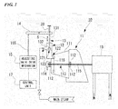
- FIG. 1 is a schematic view showing a configuration of a steam turbine 10 of the present embodiment.
- FIG. 2 is a schematic view showing a configuration of an adjusting valve drive mechanism according to a first embodiment of the steam turbine 10.
- the steam turbine 10 of the present embodiment includes a turbine main body 11, a steam channel 12 through which steam serving as a working fluid flows, an adjusting valve 13, a lever member (valve element advance/retract mechanism) 14, an adjusting valve drive mechanism 15, and a control unit 17 which controls the adjusting valve drive mechanism 15.
- the turbine main body 11 includes a tubular casing 111, a bearing 112 which is provided in the casing 111, a rotor 113 which is rotatably supported by the bearing 112 and is disposed inside the casing 111, and a speed detection sensor 114 which detects the rotating speed of the rotor 113.
- the rotor 113 includes a rotary shaft 115, and a plurality of blades 116 which are fixed to the rotary shaft 115.
- the blades 116 configured as described above are rotated by steam, and a compressor 18 is driven by the rotating force.
- the steam channel 12 is a channel which supplies steam serving as a working fluid to the turbine main body 11.
- Steam is introduced from a steam inlet port 121 on one end side of the steam channel 12.
- a steam supply port 122 on the other end side of the steam channel 12 is connected to the turbine main body 11.
- a throttle hole 123 in which the width of the channel is narrowed is provided between the steam inlet port 121 and the steam supply port 122.
- the steam channel 12 is not limited to this, and for example, the "steam channel” may be a channel through which steam extracted from the turbine main body 11 flows.
- the adjusting valve 13 adjusts the amount of the steam which is supplied to the turbine main body 11.
- the adjusting valve 13 includes a rod-shaped arm member 131, and a hemispherical sealing member (valve element) 132 which is provided on the tip portion of the arm member 131.
- a base end portion of the arm member 131 is rotatably attached to a first end portion in a longitudinal direction of the lever member 14. Since the adjusting valve 13 has the above-described configuration, the arm member 131 linearly moves along the steam channel 12, and the sealing member 132 on the tip portion of the arm member 131 is fitted to or separated from the throttle hole 123 of the steam channel 12. Accordingly, the size of an opening between the throttle hole 123 and the sealing member 132 is changed. Therefore, the flow rate of the steam which is supplied to the turbine main body 11 via the throttle hole 123 is changed.
- the lever member 14 is a member which transmits output of the adjusting valve drive mechanism 15 to the adjusting valve 13 and causes the sealing member 132 to advance toward and to retract from the steam channel 12.
- An intermediate portion in the longitudinal direction of the lever member 14 is rotatably supported.
- biasing spring 20 is attached to the first end portion of the lever member 14.
- the biasing spring 20 functions as a forcibly closing means for forcibly closing the adjusting valve 13.
- the other end of the biasing spring 20 is fixed to a frame (not shown) of the steam channel 12 or the like so as to be immovable. That is, in a state where an external force is not applied, the biasing spring 20 rotates the lever member 14 in the clockwise direction in FIG. 1 to apply a pressing force to the lever member 14.
- the adjusting valve drive mechanism 15 is a mechanism which drives the above-described adjusting valve 13.
- the adjusting valve drive mechanism 15 is connected to the other end of the lever member 14.
- the adjusting valve drive mechanism 15 rotates the lever member 14. Accordingly, the arm member 131 constituting the adjusting valve 13 is displaced in an axial direction, and an opening degree of the adjusting valve 13 is adjusted.
- the adjusting valve drive mechanism 15 includes a servo motor (rotary motor) 151, a brake 152 and a clutch 153 which are connected to a drive shaft 151s of the servo motor 151, a drive gear (spur gear) 154 which is connected to the drive shaft 151s of the servo motor 151, and a chain (straight moving portion) 155 which is wound around the drive gear 154.
- a servo motor rotary motor
- brake 152 brake 152
- a clutch 153 which are connected to a drive shaft 151s of the servo motor 151
- a drive gear (spur gear) 154 which is connected to the drive shaft 151s of the servo motor 151
- a chain (straight moving portion) 155 which is wound around the drive gear 154.
- the brake 152 is configured of an electronic disk brake.
- the brake 152 is configured so as to be operated when supply of power is cut off to stop the rotation of the servo motor 151.
- the operation of the brake 152 is controlled by the control unit 17 (refer to FIG. 1 ).
- the control unit 17 can operate the brake 152. That is, the rotation of the servo motor 151 is stopped by operating the brake 152.
- the clutch 153 is provided so as to be interposed between the drive shaft 151s of the servo motor 151 and a rotary shaft 154s of the drive gear 154.
- the clutch 153 can perform intermittent transmission of a rotating force between the drive shaft 151s and the rotary shaft 154s.
- the clutch 153 stops the transmission of the rotating force between the drive shaft 151s and the rotary shaft 154s.
- a meshing portion between the drive gear 154 and the chain 155 is formed by a spur gear which is positioned in a direction orthogonal to an advance/retract direction S of the chain 155.
- the drive gear 154 is disposed at a position separated from a second end portion of the lever member 14 in an upward-downward direction orthogonal to the longitudinal direction in which the first and second end portions of the lever member 14 are connected to each other.
- One end of the chain 155 is connected to the second end portion of the lever member 14.
- the chain 155 is wound around the drive gear 154 so as to extend in a tangential direction of the drive gear 154.
- the chain 155 advances and retracts in a predetermined advance/retract direction S which becomes the tangential direction of the drive gear 154 according to the rotation of the drive gear 154.
- the lever member 14 is swung, the arm member 131 of the adjusting valve 13 linearly moves, and the sealing member 132 of the tip portion of the arm member 131 is fitted to or separated from the throttle hole 123 of the steam channel 12. Accordingly, the flow rate steam which is supplied to the turbine main body 11 via the throttle hole 123 is changed.
- the control unit 17 controls the adjusting valve drive mechanism 15 based on the pressure or the temperature of the compressor 18 detected by a sensor (not shown) or the like, the rotating speed of the drive shaft 151s of the servo motor 151, instruction from a user, or the like, and adjusts the amount of the steam supplied to the turbine main body 11.
- the servo motor 151 is used as a drive source, unlike a hydraulic actuator, a seal for preventing leakage of oil is not provided. Accordingly, it is possible to decrease the frequency of maintenance.
- the configuration of the adjusting valve drive mechanism 15 is simple. Therefore, maintenance of the adjusting valve drive mechanism 15 and the steam turbine 10 is easily performed, and mechanical reliability increases. As a result, the maintainability increases, and it is possible to decrease the manufacturing cost and the maintenance cost.
- the chain 155 is driven via the drive gear 154 by the servo motor 151, it is possible to freely adjust the opening degree of the adjusting valve 13 by changing a rotation amount of the servo motor 151. Accordingly, unlike a configuration in which a link is rotated by a motor, the degree of freedom in the adjustment of the opening degree of the adjusting valve 13 increases.
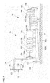
- FIG. 3 is a schematic view showing the configuration of the adjusting valve drive mechanism 15 according to the second embodiment of the steam turbine 10.
- the adjusting valve drive mechanism 15 of the present embodiment has the same adjusting valve drive mechanism 15 as that of the first embodiment.
- This adjusting valve drive mechanism 15 further includes a stage 156 and a position adjustment mechanism 16.
- the servo motor 151, the brake 152, the clutch 153, and the drive gear 154 which configure the adjusting valve drive mechanism 15 are provided on the stage 156.
- the stage 156 has an inclined surface 156t, which is inclined with respect to the advance/retract direction S, on the lower surface of the stage 156.
- the position adjustment mechanism 16 adjusts the position of the stage 156 in the advance/retract direction S.
- the position adjustment mechanism 16 includes a drive block 165 which is disposed below the stage 156 and has an opposite surface 165t facing the inclined surface 156t, and a movement mechanism which moves the drive block 165 in a direction H orthogonal to the advance/retract direction S and includes a servo motor 161, a brake 162, and a drive gear 163.
- the reduction ratio of the drive gear 154, the inclination angle of the inclined surface 156t, the reduction ratio of the drive gear 163, or the like is set such that the adjustment amount (adjustment speed) of the adjusting valve 13 in the position adjustment mechanism 16 driven by the servo motor 161 is smaller than the adjustment amount (adjustment speed) of the adjusting valve 13 in the adjusting valve drive mechanism 15 driven by the servo motor 151.
- the drive gear 163 can use a worm gear.
- the adjusting valve drive mechanism 15 of the above-described second embodiment in addition to the advance/retract operation of the adjusting valve 13 performed by the drive gear 154 and the chain 155, the advance/retract operation of the adjusting valve 13 which is performed by advancing and retracting the drive gear 154 and the chain 155 for each stage 156 is performed.
- the position of the adjusting valve 13 is approximately adjusted by the advance/retract operation performed by the chain 155 of the drive gear 154, and the position of the adjusting valve 13 can be finely adjusted by the advance/retract operation of the stage 156.
- the adjustment of the opening degree of the adjusting valve 13 is performed at two stages such as coarse adjustment and fine adjustment, it is possible to more rapidly adjust the opening degree with high accuracy.
- the stage 156 is driven by the servo motor 161 which is provided separately from the servo motor 151.
- the present invention is not limited to this.
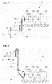
- FIG. 4 is a schematic view showing a configuration of an adjusting valve drive mechanism in a modified example of the second embodiment of the steam turbine.
- the stage 156 may be configured so as to be driven by the servo motor 151 which drives the chain 155. That is, the drive gear 163 is connected to the servo motor 151 via a clutch (switching portion) 166, transmission gears 167 and 168, and the brake 162. In addition, in the servo motor 151, a clutch (switching portion) 158 is also provided on the drive gear 154 side.
- a transmission destination of a rotary driving force of the servo motor 151 can be selectively switched to the drive gear 154 and the drive gear 163 by operating the clutches 158 and 166.
- the configuration can be simple, and the cost can decrease.
- the present invention is not limited to the above-described embodiments, and various modifications are applied to the above-described embodiments within a scope which does not depart from the gist of the present invention. That is, specific shapes, configurations, or the like described in the embodiments are examples, and may be appropriately modified.
- FIG. 5 is a schematic view showing a configuration of a first modified example of the adjusting valve drive mechanism.
- a pinion gear 171 and a rack gear 172 can be used as the spur gear and the straight moving portion.
- the upper end portion of the rack gear 172 is connected to the lever member 14 by a pin 173.
- a pressing member 174 such as a spring is provided in the adjusting valve drive mechanism 15 of the first modification.
- a folding gear 180 may be provided on the upper portion such that the chain 155 is folded and the tip portion of the lever member 14 is advanced and retracted from the upper portion.
- a pulley gear 181 which functions as a free pulley may be provided on the tip portion of the lever member 14, one end 155a of the chain 155 and the drive gear 154 may be fixed above the pulley gear 181, and the intermediate portion of the chain 155 is wound around the pulley gear 181. Accordingly, it is possible to decrease the rotating force of the servo motor 151.
- a transmission gear 183 having different diameters may be interposed between the drive gear 154 and the chain 155 so as to increase or decrease the rotating force of the servo motor 151 and transmit the force to the drive gear 154.
- the entire configuration or the like of the adjusting valve drive mechanism 15 or the steam turbine 10 may be appropriately modified if it is within the scope of the gist of the present invention.
- the adjusting valve drive mechanism or the steam turbine it is possible to increase the degree of freedom in adjustment of the opening degree without spending time on maintenance in spite of the long-term use.
Landscapes
- Engineering & Computer Science (AREA)
- Mechanical Engineering (AREA)
- General Engineering & Computer Science (AREA)
- Chemical & Material Sciences (AREA)
- Combustion & Propulsion (AREA)
- Control Of Turbines (AREA)
- Transmission Devices (AREA)
- Lift Valve (AREA)
- Mechanically-Actuated Valves (AREA)
Abstract
Description
- The present invention relates to an adjusting valve drive mechanism of a steam turbine which is rotationally driven by steam, and a steam turbine.
- Priority is claimed on
Japanese Patent Application No. 2013-261807, filed December 18, 2013 - A steam turbine is used so as to drive a machine or the like, and includes a turbine main body having a rotor which is rotatably supported. The rotor is rotationally driven by supplying steam serving as a working fluid to the turbine main body. Steam supplied to the turbine main body or steam extracted from the turbine main body flows to a steam channel of the steam turbine. An adjusting valve is provided in the steam channel. By adjusting an opening degree of the adjusting valve, it is possible to adjust the flow rate of the steam which is supplied to the turbine main body.
- The adjusting valve is driven by an adjusting valve drive mechanism. For example, as described in Patent Document 1, as the adjusting valve drive mechanism, in general, a hydraulic actuator is used.
- In addition, Patent Document 2 discloses a configuration in which an opening degree of an adjusting valve is adjusted via a link by an electric motor.
- Moreover, for example, Patent Documents 3 and 4 disclose an adjusting valve drive mechanism which includes an electric motor, and a conversion mechanism such as a ball screw which converts a rotation movement of the electric motor into a linear movement of an adjusting valve.
-
- Patent Document 1:
Japanese Unexamined Patent Application, First Publication No. H8-219322 - Patent Document 2:
Japanese Unexamined Utility Model Application, First Publication No. H2-29368 - Patent Document 3:
Japanese Unexamined Patent Application, First Publication No. 2013-72349 - Patent Document 4:
Japanese Unexamined Patent Application, First Publication No. H5-257538 - As disclosed in Patent Document 1, in the configuration which uses the hydraulic actuator, if the steam turbine is operated for a long period, a packing which is provided in a sliding portion of the hydraulic actuator deteriorates. As a result, hydraulic oil is likely to leak out from the portion of the packing. In addition, in the hydraulic actuator, since a hydraulic circuit hydraulically driven is complicated, maintenance takes a lot of time.
- In the mechanism disclosed in Patent Document 2, the opening degree of the adjusting valve is adjusted via the link by the electric motor. Accordingly, a rotation amount of the electric motor and a change of the opening degree of the adjusting valve are determined by a lever ratio of the link. In this case, since a rotation range of the link is regulated by the set lever ratio, adjustment of a large opening degree may be difficult, or adjustment of a minute opening degree may be difficult.
- In the configurations disclosed in Patent Documents 3 and 4, the problems in the configurations disclosed in Patent Documents 1 and 2 can be solved. However, in the configurations disclosed in Patent Documents 3 and 4, a ball screw is used. In the ball screw, a meshing portion having a predetermined contact angle is provided in a spiral screw groove. Accordingly, if opening and closing operations of the adjusting valve are repeated for a long period, only a specific portion of the meshing portion of the ball screw is abraded. Therefore, it may be necessary to perform regular maintenance with respect to the ball screw.
- The present invention provides an adjusting valve drive mechanism and a steam turbine capable of increasing a degree of freedom in adjustment of an opening degree without spending time on maintenance in spite of the long-term use.
- According a first aspect of the present invention, an adjusting valve drive mechanism of an adjusting valve which opens and closes a steam channel, through which steam flows, by a valve element so as to adjust a flow rate of the steam serving as a working fluid of a steam turbine, the adjusting valve drive mechanism includes: a rotary motor; a spur gear which is rotated by the rotary motor; and a straight moving portion which meshes with teeth of the spur gear, advances and retreats in a predetermined advance/retract direction which is a tangential direction of the spur gear in accordance with rotation of the spur gear, and opens and closes the adjusting valve.
- In this way, since the rotary motor is used as a drive source, maintenance of a seal for preventing oil leakage of a hydraulic actuator is not required, and the amount of maintenance decreases.
- In addition, since a complicated hydraulic circuit is not required, the configuration of the mechanism is simple.
- Moreover, since the meshing between the spur gear and the straight movement mechanism is performed in a direction orthogonal to the advance/retract direction, unlike a case where a meshing direction is inclined to the advance/retract direction such as a thread of a ball screw or a helical gear, it is possible to decrease abrasion of the meshing portion.
- In addition, since the straight moving portion is driven via the spur gear by the rotary motor, it is possible to freely adjust the opening degree of the adjusting valve by changing the rotation amount of the rotary motor.
- According to a second aspect of the present invention, in the adjusting valve drive mechanism according to the first aspect, the straight moving portion may be a chain which meshes with the teeth of the spur gear and extends in the advance/retract direction from the spur gear.
- According to this configuration, it is possible to advance and retract the chain by the spur gear to advance and retract the adjusting valve.
- According to a third aspect of the present invention, in the adjusting valve drive mechanism according to the first aspect, the straight moving portion may be a rack gear which meshes with the teeth of the spur gear.
- According to this configuration, the spur gear and the rack gear can constitute a so-called rack and pinion mechanism, and it is possible to advance and retract the rack gear by the spur gear to open and close the adjusting valve.
- According to a fourth aspect of the present invention, the adjusting valve drive mechanism according to any one of the first to third aspects may further include a stage which supports the spur gear and the straight moving portion, and a position adjustment mechanism which adjusts a position of the stage along the advance/retract direction.
- According to this configuration, in addition to the advance/retract operation of the adjusting valve performed by the spur gear and the straight moving portion, it is possible to perform the advance/retract operation of the adjusting valve carried by advancing and retracting the spur gear and the straight moving portion for each stage.
- Moreover, the position of the adjusting valve is approximately adjusted by the advance/retract operation using the straight moving portion of the spur gear, and it is possible to perform fine adjustment of the position of the adjusting valve using the advance/retract operation of the stage.
- According to a fifth aspect of the present invention, in the adjusting valve drive mechanism according to the fourth aspect, the stage may include an inclined surface which is inclined with respect to the advance/retract direction, and the position adjustment mechanism may include a drive block having an opposite surface facing the inclined surface, and a movement mechanism which moves the drive block in a direction orthogonal to the advance/retract direction.
- According to this configuration, if the drive block moves in the direction orthogonal to the advance/retract direction, the inclined surface slides along the opposite surface of the drive block, and the stage moves in the advance/retract direction. Therefore, it is possible to adjust the position of the adjusting valve.
- According to a sixth aspect of the present invention, in the adjusting valve drive mechanism according to the fourth or fifth aspect, the position adjustment mechanism may adjust the position of the stage by the rotary motor, and a switching portion which switches transmission of a rotary driving force of the rotary motor between the spur gear side and the position adjustment mechanism side may be provided.
- According to this configuration, it is possible to share the drive source which advances and retracts the straight moving portion and the drive source which advances and retracts the stage.
- According to a seventh aspect of the present invention, the adjusting valve drive mechanism according to any one of the first to sixth aspects may further include a brake which forcibly stops the rotation of the rotary motor.
- Accordingly, for example, in a case where an emergency occurs or the like, it is possible to stop the rotation of the rotary motor by the brake.
- According to an eighth aspect of the present invention, the adjusting valve drive mechanism according to any one of the first to seventh aspects may further include a clutch which intermittently transmits a rotating force of the rotary motor to the spur gear.
- Accordingly, it is possible to intermittently transmit the rotating force of the rotary motor to the spur gear.
- According to a ninth aspect of the present invention, a steam turbine, includes: a turbine main body having a blade which is rotatably supported; a steam channel which is connected to the turbine main body and through which steam flows; an adjusting valve which straightly moves and adjusts opening and closing of the steam channel; and the adjusting valve drive mechanism according to any one of the first to eighth aspects which drives the adjusting valve.
- According to this configuration, the load of maintenance with respect to the adjusting valve drive mechanism of the steam turbine decreases, and the configuration of the mechanism is simple. As a result, it is possible to decrease abrasion of the meshing portion.
- According to the above-described adjusting valve drive mechanism and the steam turbine, it is possible to increase the degree of freedom in adjustment of an opening degree without spending time on maintenance in spite of the long-term use.
-
-
FIG. 1 is a schematic view showing the entire configuration of a steam turbine according to an embodiment of the present invention. -
FIG. 2 is a schematic view showing a configuration of an adjusting valve drive mechanism according to a first embodiment of the steam turbine. -
FIG. 3 is a schematic view showing a configuration of an adjusting valve drive mechanism according to a second embodiment of the steam turbine. -
FIG. 4 is a schematic view showing a configuration of an adjusting valve drive mechanism according to a modified example of the second embodiment of the steam turbine. -
FIG. 5 is a schematic view showing a configuration of a first modified example of the adjusting valve drive mechanism. -
FIG. 6 is a schematic view showing a configuration of a second modified example of the adjusting valve drive mechanism. -
FIG. 7 is a schematic view showing a configuration of a third modified example of the adjusting valve drive mechanism. -
FIG. 8 is a schematic view showing a configuration of a fourth modified example of the adjusting valve drive mechanism. - Hereinafter, a steam turbine according to an embodiment of the present invention will be described with reference to the drawings.
-
FIG. 1 is a schematic view showing a configuration of asteam turbine 10 of the present embodiment.FIG. 2 is a schematic view showing a configuration of an adjusting valve drive mechanism according to a first embodiment of thesteam turbine 10. - As shown in
FIG. 1 , thesteam turbine 10 of the present embodiment includes a turbinemain body 11, asteam channel 12 through which steam serving as a working fluid flows, an adjustingvalve 13, a lever member (valve element advance/retract mechanism) 14, an adjustingvalve drive mechanism 15, and acontrol unit 17 which controls the adjustingvalve drive mechanism 15. - The turbine
main body 11 includes atubular casing 111, abearing 112 which is provided in thecasing 111, arotor 113 which is rotatably supported by thebearing 112 and is disposed inside thecasing 111, and aspeed detection sensor 114 which detects the rotating speed of therotor 113. Therotor 113 includes arotary shaft 115, and a plurality ofblades 116 which are fixed to therotary shaft 115. - The
blades 116 configured as described above are rotated by steam, and acompressor 18 is driven by the rotating force. - The
steam channel 12 is a channel which supplies steam serving as a working fluid to the turbinemain body 11. - Steam is introduced from a
steam inlet port 121 on one end side of thesteam channel 12. Asteam supply port 122 on the other end side of thesteam channel 12 is connected to the turbinemain body 11. Moreover, athrottle hole 123 in which the width of the channel is narrowed is provided between thesteam inlet port 121 and thesteam supply port 122. Moreover, in the present embodiment, the case is described in which the "steam channel" according to the present invention is the channel through which the steam supplied to turbinemain body 11 flows. However, thesteam channel 12 is not limited to this, and for example, the "steam channel" may be a channel through which steam extracted from the turbinemain body 11 flows. - The adjusting
valve 13 adjusts the amount of the steam which is supplied to the turbinemain body 11. The adjustingvalve 13 includes a rod-shapedarm member 131, and a hemispherical sealing member (valve element) 132 which is provided on the tip portion of thearm member 131. A base end portion of thearm member 131 is rotatably attached to a first end portion in a longitudinal direction of thelever member 14. Since the adjustingvalve 13 has the above-described configuration, thearm member 131 linearly moves along thesteam channel 12, and the sealingmember 132 on the tip portion of thearm member 131 is fitted to or separated from thethrottle hole 123 of thesteam channel 12. Accordingly, the size of an opening between thethrottle hole 123 and the sealingmember 132 is changed. Therefore, the flow rate of the steam which is supplied to the turbinemain body 11 via thethrottle hole 123 is changed. - The
lever member 14 is a member which transmits output of the adjustingvalve drive mechanism 15 to the adjustingvalve 13 and causes the sealingmember 132 to advance toward and to retract from thesteam channel 12. An intermediate portion in the longitudinal direction of thelever member 14 is rotatably supported. - In addition, one end of a biasing
spring 20 is attached to the first end portion of thelever member 14. The biasingspring 20 functions as a forcibly closing means for forcibly closing the adjustingvalve 13. The other end of the biasingspring 20 is fixed to a frame (not shown) of thesteam channel 12 or the like so as to be immovable. That is, in a state where an external force is not applied, the biasingspring 20 rotates thelever member 14 in the clockwise direction inFIG. 1 to apply a pressing force to thelever member 14. - The adjusting
valve drive mechanism 15 is a mechanism which drives the above-describedadjusting valve 13. - As shown in
FIG. 2 , the adjustingvalve drive mechanism 15 is connected to the other end of thelever member 14. The adjustingvalve drive mechanism 15 rotates thelever member 14. Accordingly, thearm member 131 constituting the adjustingvalve 13 is displaced in an axial direction, and an opening degree of the adjustingvalve 13 is adjusted. - The adjusting
valve drive mechanism 15 includes a servo motor (rotary motor) 151, abrake 152 and a clutch 153 which are connected to adrive shaft 151s of theservo motor 151, a drive gear (spur gear) 154 which is connected to thedrive shaft 151s of theservo motor 151, and a chain (straight moving portion) 155 which is wound around thedrive gear 154. - The
brake 152 is configured of an electronic disk brake. Thebrake 152 is configured so as to be operated when supply of power is cut off to stop the rotation of theservo motor 151. The operation of thebrake 152 is controlled by the control unit 17 (refer toFIG. 1 ). In a case where a circumferential speed of thedrive shaft 151s exceeds a threshold value, thecontrol unit 17 can operate thebrake 152. That is, the rotation of theservo motor 151 is stopped by operating thebrake 152. - The clutch 153 is provided so as to be interposed between the
drive shaft 151s of theservo motor 151 and arotary shaft 154s of thedrive gear 154. The clutch 153 can perform intermittent transmission of a rotating force between thedrive shaft 151s and therotary shaft 154s. - In a case where the operation of the clutch 153 is controlled by the
control unit 17 and any abnormalities of thecontrol unit 17 are detected, or the like, the clutch 153 stops the transmission of the rotating force between thedrive shaft 151s and therotary shaft 154s. - A meshing portion between the
drive gear 154 and thechain 155 is formed by a spur gear which is positioned in a direction orthogonal to an advance/retract direction S of thechain 155. Thedrive gear 154 is disposed at a position separated from a second end portion of thelever member 14 in an upward-downward direction orthogonal to the longitudinal direction in which the first and second end portions of thelever member 14 are connected to each other. One end of thechain 155 is connected to the second end portion of thelever member 14. Thechain 155 is wound around thedrive gear 154 so as to extend in a tangential direction of thedrive gear 154. Thechain 155 advances and retracts in a predetermined advance/retract direction S which becomes the tangential direction of thedrive gear 154 according to the rotation of thedrive gear 154. According to the advance and retract of thechain 155, thelever member 14 is swung, thearm member 131 of the adjustingvalve 13 linearly moves, and the sealingmember 132 of the tip portion of thearm member 131 is fitted to or separated from thethrottle hole 123 of thesteam channel 12. Accordingly, the flow rate steam which is supplied to the turbinemain body 11 via thethrottle hole 123 is changed. - The
control unit 17 controls the adjustingvalve drive mechanism 15 based on the pressure or the temperature of thecompressor 18 detected by a sensor (not shown) or the like, the rotating speed of thedrive shaft 151s of theservo motor 151, instruction from a user, or the like, and adjusts the amount of the steam supplied to the turbinemain body 11. - Therefore, according to the adjusting
valve drive mechanism 15 and thesteam turbine 10 of the above-described first embodiment, since theservo motor 151 is used as a drive source, unlike a hydraulic actuator, a seal for preventing leakage of oil is not provided. Accordingly, it is possible to decrease the frequency of maintenance. In addition, unlike the hydraulic actuator, since a complicated hydraulic circuit is not provided, the configuration of the adjustingvalve drive mechanism 15 is simple. Therefore, maintenance of the adjustingvalve drive mechanism 15 and thesteam turbine 10 is easily performed, and mechanical reliability increases. As a result, the maintainability increases, and it is possible to decrease the manufacturing cost and the maintenance cost. - In addition, since the meshing between the
drive gear 154 and the straight movement mechanism is performed in the direction orthogonal to the advance/retract direction S, unlike a case where a meshing direction is inclined in the advance/retract direction S such as a thread of a ball screw or a helical gear, it is possible to decrease abrasion of the meshing portion. - Moreover, since the
chain 155 is driven via thedrive gear 154 by theservo motor 151, it is possible to freely adjust the opening degree of the adjustingvalve 13 by changing a rotation amount of theservo motor 151. Accordingly, unlike a configuration in which a link is rotated by a motor, the degree of freedom in the adjustment of the opening degree of the adjustingvalve 13 increases. - Next, a second embodiment of the adjusting
valve drive mechanism 15 and thesteam turbine 10 according to the present invention will be described. In the second embodiment described below, since only the configuration of the adjustingvalve drive mechanism 15 is different from that of the first embodiment, the same reference numerals are assigned to the same portions as those of the first embodiment, and overlapping descriptions thereof are omitted. -
FIG. 3 is a schematic view showing the configuration of the adjustingvalve drive mechanism 15 according to the second embodiment of thesteam turbine 10. - As shown in
FIG. 3 , the adjustingvalve drive mechanism 15 of the present embodiment has the same adjustingvalve drive mechanism 15 as that of the first embodiment. This adjustingvalve drive mechanism 15 further includes astage 156 and aposition adjustment mechanism 16. - The
servo motor 151, thebrake 152, the clutch 153, and thedrive gear 154 which configure the adjustingvalve drive mechanism 15 are provided on thestage 156. Thestage 156 has aninclined surface 156t, which is inclined with respect to the advance/retract direction S, on the lower surface of thestage 156. - The
position adjustment mechanism 16 adjusts the position of thestage 156 in the advance/retract direction S. Theposition adjustment mechanism 16 includes adrive block 165 which is disposed below thestage 156 and has anopposite surface 165t facing theinclined surface 156t, and a movement mechanism which moves thedrive block 165 in a direction H orthogonal to the advance/retract direction S and includes aservo motor 161, abrake 162, and adrive gear 163. - Here, the reduction ratio of the
drive gear 154, the inclination angle of theinclined surface 156t, the reduction ratio of thedrive gear 163, or the like is set such that the adjustment amount (adjustment speed) of the adjustingvalve 13 in theposition adjustment mechanism 16 driven by theservo motor 161 is smaller than the adjustment amount (adjustment speed) of the adjustingvalve 13 in the adjustingvalve drive mechanism 15 driven by theservo motor 151. For example, thedrive gear 163 can use a worm gear. - Therefore, according to the adjusting
valve drive mechanism 15 of the above-described second embodiment, in addition to the advance/retract operation of the adjustingvalve 13 performed by thedrive gear 154 and thechain 155, the advance/retract operation of the adjustingvalve 13 which is performed by advancing and retracting thedrive gear 154 and thechain 155 for eachstage 156 is performed. As a result, the position of the adjustingvalve 13 is approximately adjusted by the advance/retract operation performed by thechain 155 of thedrive gear 154, and the position of the adjustingvalve 13 can be finely adjusted by the advance/retract operation of thestage 156. - Moreover, similarly to the first embodiment, since the
servo motors valve 13 at low cost. - In addition, since the adjustment of the opening degree of the adjusting
valve 13 is performed at two stages such as coarse adjustment and fine adjustment, it is possible to more rapidly adjust the opening degree with high accuracy. - Here, in the second embodiment, the
stage 156 is driven by theservo motor 161 which is provided separately from theservo motor 151. However, the present invention is not limited to this. -
FIG. 4 is a schematic view showing a configuration of an adjusting valve drive mechanism in a modified example of the second embodiment of the steam turbine. - As shown in
FIG. 4 , thestage 156 may be configured so as to be driven by theservo motor 151 which drives thechain 155. That is, thedrive gear 163 is connected to theservo motor 151 via a clutch (switching portion) 166, transmission gears 167 and 168, and thebrake 162. In addition, in theservo motor 151, a clutch (switching portion) 158 is also provided on thedrive gear 154 side. - In this configuration, a transmission destination of a rotary driving force of the
servo motor 151 can be selectively switched to thedrive gear 154 and thedrive gear 163 by operating theclutches - According to this configuration, since the drive source which advances and retracts the
chain 155 and the drive source which advances and retracts thestage 156 can be shared, the configuration can be simple, and the cost can decrease. - In addition, the present invention is not limited to the above-described embodiments, and various modifications are applied to the above-described embodiments within a scope which does not depart from the gist of the present invention. That is, specific shapes, configurations, or the like described in the embodiments are examples, and may be appropriately modified.
- For example,
FIG. 5 is a schematic view showing a configuration of a first modified example of the adjusting valve drive mechanism. - As shown in
FIG. 5 , instead of thedrive gear 154 and thechain 155, apinion gear 171 and arack gear 172 can be used as the spur gear and the straight moving portion. In this case, in order to follow the swinging of thelever member 14, the upper end portion of therack gear 172 is connected to thelever member 14 by apin 173. In the adjustingvalve drive mechanism 15 of the first modification, for example, in order to press thelever member 14 to thepinion gear 171, preferably, a pressingmember 174 such as a spring is provided. - Moreover, for example, as a second modified example shown in
FIG. 6 , in a case where the first end portion in the longitudinal direction of thelever member 14 is rotatably supported and the adjustingvalve 13 is provided on the intermediate portion in the longitudinal direction of thelever member 14, or the like, afolding gear 180 may be provided on the upper portion such that thechain 155 is folded and the tip portion of thelever member 14 is advanced and retracted from the upper portion. - Moreover, as a third modified example shown in
FIG. 7 , apulley gear 181 which functions as a free pulley may be provided on the tip portion of thelever member 14, oneend 155a of thechain 155 and thedrive gear 154 may be fixed above thepulley gear 181, and the intermediate portion of thechain 155 is wound around thepulley gear 181. Accordingly, it is possible to decrease the rotating force of theservo motor 151. - In addition, as a fourth modified example shown in
FIG. 8 , atransmission gear 183 having different diameters may be interposed between thedrive gear 154 and thechain 155 so as to increase or decrease the rotating force of theservo motor 151 and transmit the force to thedrive gear 154. - Accordingly, it is possible to decrease application torque of the
servo motor 151, and it is possible to suitably set capacity of theservo motor 151. - Moreover, the entire configuration or the like of the adjusting
valve drive mechanism 15 or thesteam turbine 10 may be appropriately modified if it is within the scope of the gist of the present invention. - According to the adjusting valve drive mechanism or the steam turbine, it is possible to increase the degree of freedom in adjustment of the opening degree without spending time on maintenance in spite of the long-term use.
-
- 10:
- steam turbine
- 11:
- turbine main body
- 12:
- steam channel
- 13:
- adjusting valve
- 14:
- lever member
- 15:
- adjusting valve drive mechanism
- 16:
- position adjustment mechanism
- 17:
- control unit
- 116:
- blade
- 131:
- arm member
- 132:
- sealing member (valve element)
- 151:
- servo motor (rotary motor)
- 151s:
- drive shaft
- 152:
- brake
- 153:
- clutch
- 154:
- drive gear (spur gear)
- 155:
- chain (straight moving portion)
- 156:
- stage
- 156t:
- inclined surface
- 165:
- drive block
- 158, 166:
- clutch (switching portion)
- 171:
- pinion gear (spur gear)
- 172:
- rack gear (straight moving portion)
Claims (9)
- An adjusting valve drive mechanism of an adjusting valve which opens and closes a steam channel, through which steam flows, by a valve element so as to adjust a flow rate of the steam serving as a working fluid of a steam turbine, the adjusting valve drive mechanism comprising:a rotary motor;a spur gear which is rotated by the rotary motor; anda straight moving portion which meshes with teeth of the spur gear, advances and retreats in a predetermined advance/retract direction which is a tangential direction of the spur gear in accordance with rotation of the spur gear, and opens and closes the adjusting valve.
- The adjusting valve drive mechanism according to claim 1,
wherein the straight moving portion is a chain which meshes with the teeth of the spur gear and extends in the advance/retract direction from the spur gear. - The adjusting valve drive mechanism according to claim 1,
wherein the straight moving portion is a rack gear which meshes with the teeth of the spur gear. - The adjusting valve drive mechanism according to any one of claims 1 to 3, further comprising:a stage which supports the spur gear and the straight moving portion; anda position adjustment mechanism which adjusts a position of the stage along the advance/retract direction.
- The adjusting valve drive mechanism according to claim 4,
wherein the stage includes an inclined surface which is inclined with respect to the advance/retract direction, and
wherein the position adjustment mechanism includes a drive block having an opposite surface facing the inclined surface, and a movement mechanism which moves the drive block in a direction orthogonal to the advance/retract direction. - The adjusting valve drive mechanism according to claim 4 or 5, wherein the position adjustment mechanism adjusts the position of the stage by the rotary motor, and
wherein a switching portion which switches transmission of a rotary driving force of the rotary motor between the spur gear side and the position adjustment mechanism side is provided. - The adjusting valve drive mechanism according to any one of claims 1 to 6, further comprising:a brake which forcibly stops the rotation of the rotary motor.
- The adjusting valve drive mechanism according to any one of claims 1 to 7, further comprising:a clutch which intermittently transmits a rotating force of the rotary motor to the spur gear.
- A steam turbine, comprising:a turbine main body having a blade which is rotatably supported;a steam channel which is connected to the turbine main body and through which steam flows;an adjusting valve which straightly moves and adjusts opening and closing of the steam channel; andthe adjusting valve drive mechanism according to any one of claims 1 to 8 which drives the adjusting valve.
Applications Claiming Priority (2)
| Application Number | Priority Date | Filing Date | Title |
|---|---|---|---|
| JP2013261807A JP6165047B2 (en) | 2013-12-18 | 2013-12-18 | Regulating valve drive mechanism, steam turbine |
| PCT/JP2014/078584 WO2015093151A1 (en) | 2013-12-18 | 2014-10-28 | Adjusting valve drive mechanism and steam turbine |
Publications (2)
| Publication Number | Publication Date |
|---|---|
| EP3085903A1 true EP3085903A1 (en) | 2016-10-26 |
| EP3085903A4 EP3085903A4 (en) | 2017-01-04 |
Family
ID=53402508
Family Applications (1)
| Application Number | Title | Priority Date | Filing Date |
|---|---|---|---|
| EP14871770.5A Withdrawn EP3085903A4 (en) | 2013-12-18 | 2014-10-28 | Adjusting valve drive mechanism and steam turbine |
Country Status (5)
| Country | Link |
|---|---|
| US (1) | US20160290173A1 (en) |
| EP (1) | EP3085903A4 (en) |
| JP (1) | JP6165047B2 (en) |
| CN (1) | CN105765171A (en) |
| WO (1) | WO2015093151A1 (en) |
Families Citing this family (1)
| Publication number | Priority date | Publication date | Assignee | Title |
|---|---|---|---|---|
| CN107269325A (en) * | 2017-08-04 | 2017-10-20 | 中国船舶重工集团公司第七0三研究所 | Positive car drive device |
Family Cites Families (21)
| Publication number | Priority date | Publication date | Assignee | Title |
|---|---|---|---|---|
| GB277368A (en) * | 1926-09-11 | 1928-02-23 | Siemens - Schuckertwerke Aktiengesellschaft | |
| US2307437A (en) * | 1938-11-19 | 1943-01-05 | Walckena Francois Mar Athanase | Control device for steam locomotives |
| US2239602A (en) * | 1939-06-28 | 1941-04-22 | Westinghouse Electric & Mfg Co | Governing apparatus |
| US2312958A (en) * | 1939-10-25 | 1943-03-02 | Gen Electric | Wide range turbine governing arrangement |
| US2895491A (en) * | 1958-03-17 | 1959-07-21 | Allis Chalmers Mfg Co | Inlet valve supporting and actuating mechanism for elastic fluid turbines |
| US3141348A (en) * | 1961-08-28 | 1964-07-21 | Allis Chalmers Mfg Co | Operating mechanism |
| US4457657A (en) * | 1981-07-21 | 1984-07-03 | Beloit Corporation | Integral paper collection and transfer assembly |
| JPH0756177B2 (en) * | 1986-12-22 | 1995-06-14 | 日成ビルド工業株式会社 | Horizontal transfer device for pallets in car parking system |
| JPH0229368U (en) | 1988-08-17 | 1990-02-26 | ||
| TW219998B (en) | 1991-10-04 | 1994-02-01 | Gen Electric | |
| JPH05139404A (en) * | 1991-11-18 | 1993-06-08 | Mitsui Matsushima Co Ltd | Support for bagged article |
| JP2583506Y2 (en) * | 1992-02-18 | 1998-10-22 | 小糸工業株式会社 | Automatic turning device |
| JP3626230B2 (en) * | 1994-12-15 | 2005-03-02 | 株式会社東芝 | Steam turbine valve and steam turbine valve opening control device |
| JP3367252B2 (en) | 1995-02-16 | 2003-01-14 | 富士電機株式会社 | Actuator device for opening and closing steam control valve |
| WO1998013633A1 (en) * | 1996-09-26 | 1998-04-02 | Siemens Aktiengesellschaft | Turbine valve actuator |
| US20040094077A1 (en) * | 1999-11-03 | 2004-05-20 | Stone Robert M. | Safety toe-sensor for lift table |
| US6431823B1 (en) * | 2000-07-13 | 2002-08-13 | Yudko Slepoy | Centrifugal pump with variable capacity and pressure |
| JP5674521B2 (en) * | 2011-03-25 | 2015-02-25 | 株式会社東芝 | Steam valve device and steam turbine plant |
| JP5863362B2 (en) | 2011-09-28 | 2016-02-16 | 三菱重工コンプレッサ株式会社 | Steam turbine |
| CN102699888A (en) * | 2012-05-22 | 2012-10-03 | 湖州精圆数控设备有限公司 | Lifting type work table |
| EP2937520B1 (en) * | 2012-12-21 | 2017-09-20 | Mitsubishi Hitachi Power Systems, Ltd. | Steam valve and steam turbine |
-
2013
- 2013-12-18 JP JP2013261807A patent/JP6165047B2/en not_active Expired - Fee Related
-
2014
- 2014-10-28 WO PCT/JP2014/078584 patent/WO2015093151A1/en not_active Ceased
- 2014-10-28 US US15/038,278 patent/US20160290173A1/en not_active Abandoned
- 2014-10-28 CN CN201480064145.6A patent/CN105765171A/en active Pending
- 2014-10-28 EP EP14871770.5A patent/EP3085903A4/en not_active Withdrawn
Also Published As
| Publication number | Publication date |
|---|---|
| US20160290173A1 (en) | 2016-10-06 |
| JP2015117640A (en) | 2015-06-25 |
| WO2015093151A1 (en) | 2015-06-25 |
| JP6165047B2 (en) | 2017-07-19 |
| CN105765171A (en) | 2016-07-13 |
| EP3085903A4 (en) | 2017-01-04 |
Similar Documents
| Publication | Publication Date | Title |
|---|---|---|
| JP5741252B2 (en) | Electric scissors | |
| EP1671005B1 (en) | Improved arrangement in a swing door apparatus provided with a door closer | |
| JP5278779B2 (en) | Oil pump | |
| JP6222599B2 (en) | Regulating valve drive mechanism, steam turbine | |
| US10287907B2 (en) | Linear motion mechanism, governing valve drive device, and steam turbine | |
| CN104421209B (en) | regulator structure and centrifugal compressor | |
| EP3947877B1 (en) | Automatic door operator | |
| CA2560815A1 (en) | Actuator for adjusting a rotor blade pitch angle | |
| WO2009133334A3 (en) | A variable geometry turbine | |
| US20160290173A1 (en) | Adjusting valve drive mechanism and steam turbine | |
| US8973605B2 (en) | Actuating device for housed or housingless valves | |
| CN200961600Y (en) | Digital hydraulic oil cylinder | |
| EP2650072B1 (en) | Automatic threading machine | |
| US20170328233A1 (en) | Valve device and steam turbine | |
| JP2015117640A5 (en) | ||
| CN219576797U (en) | Anti-blocking rotary motor and reciprocating mechanism driven by same | |
| CN203488437U (en) | Regulator structure and centrifugal compressor | |
| JP5996509B2 (en) | Flow control device | |
| JP2006009876A (en) | Electric and hydraulic actuator for driving valve | |
| KR102021933B1 (en) | Reduction gear of machine tool | |
| KR20040074804A (en) | brake apparatus of a landscape windmill | |
| KR200312831Y1 (en) | brake apparatus of a landscape windmill | |
| CN102777315A (en) | Pure manual control hydraulic closed-loop device of speed controller |
Legal Events
| Date | Code | Title | Description |
|---|---|---|---|
| PUAI | Public reference made under article 153(3) epc to a published international application that has entered the european phase |
Free format text: ORIGINAL CODE: 0009012 |
|
| 17P | Request for examination filed |
Effective date: 20160523 |
|
| AK | Designated contracting states |
Kind code of ref document: A1 Designated state(s): AL AT BE BG CH CY CZ DE DK EE ES FI FR GB GR HR HU IE IS IT LI LT LU LV MC MK MT NL NO PL PT RO RS SE SI SK SM TR |
|
| AX | Request for extension of the european patent |
Extension state: BA ME |
|
| A4 | Supplementary search report drawn up and despatched |
Effective date: 20161205 |
|
| RIC1 | Information provided on ipc code assigned before grant |
Ipc: F01D 17/10 20060101AFI20161129BHEP Ipc: F16H 19/02 20060101ALI20161129BHEP Ipc: F16H 19/04 20060101ALI20161129BHEP |
|
| DAX | Request for extension of the european patent (deleted) | ||
| 17Q | First examination report despatched |
Effective date: 20170921 |
|
| GRAP | Despatch of communication of intention to grant a patent |
Free format text: ORIGINAL CODE: EPIDOSNIGR1 |
|
| INTG | Intention to grant announced |
Effective date: 20180530 |
|
| STAA | Information on the status of an ep patent application or granted ep patent |
Free format text: STATUS: THE APPLICATION IS DEEMED TO BE WITHDRAWN |
|
| 18D | Application deemed to be withdrawn |
Effective date: 20181010 |