EP3085899B1 - Mittelturbinenrahmen mit abgedichtetem torsionskasten für ein gasturbinentriebwerk - Google Patents
Mittelturbinenrahmen mit abgedichtetem torsionskasten für ein gasturbinentriebwerk Download PDFInfo
- Publication number
- EP3085899B1 EP3085899B1 EP16166717.5A EP16166717A EP3085899B1 EP 3085899 B1 EP3085899 B1 EP 3085899B1 EP 16166717 A EP16166717 A EP 16166717A EP 3085899 B1 EP3085899 B1 EP 3085899B1
- Authority
- EP
- European Patent Office
- Prior art keywords
- turbine
- torque box
- mid
- inner frame
- passage
- Prior art date
- Legal status (The legal status is an assumption and is not a legal conclusion. Google has not performed a legal analysis and makes no representation as to the accuracy of the status listed.)
- Active
Links
Images


Classifications
-
- F—MECHANICAL ENGINEERING; LIGHTING; HEATING; WEAPONS; BLASTING
- F01—MACHINES OR ENGINES IN GENERAL; ENGINE PLANTS IN GENERAL; STEAM ENGINES
- F01D—NON-POSITIVE DISPLACEMENT MACHINES OR ENGINES, e.g. STEAM TURBINES
- F01D25/00—Component parts, details, or accessories, not provided for in, or of interest apart from, other groups
- F01D25/28—Supporting or mounting arrangements, e.g. for turbine casing
-
- F—MECHANICAL ENGINEERING; LIGHTING; HEATING; WEAPONS; BLASTING
- F01—MACHINES OR ENGINES IN GENERAL; ENGINE PLANTS IN GENERAL; STEAM ENGINES
- F01D—NON-POSITIVE DISPLACEMENT MACHINES OR ENGINES, e.g. STEAM TURBINES
- F01D11/00—Preventing or minimising internal leakage of working-fluid, e.g. between stages
- F01D11/003—Preventing or minimising internal leakage of working-fluid, e.g. between stages by packing rings; Mechanical seals
-
- F—MECHANICAL ENGINEERING; LIGHTING; HEATING; WEAPONS; BLASTING
- F01—MACHINES OR ENGINES IN GENERAL; ENGINE PLANTS IN GENERAL; STEAM ENGINES
- F01D—NON-POSITIVE DISPLACEMENT MACHINES OR ENGINES, e.g. STEAM TURBINES
- F01D25/00—Component parts, details, or accessories, not provided for in, or of interest apart from, other groups
- F01D25/08—Cooling; Heating; Heat-insulation
- F01D25/12—Cooling
-
- F—MECHANICAL ENGINEERING; LIGHTING; HEATING; WEAPONS; BLASTING
- F01—MACHINES OR ENGINES IN GENERAL; ENGINE PLANTS IN GENERAL; STEAM ENGINES
- F01D—NON-POSITIVE DISPLACEMENT MACHINES OR ENGINES, e.g. STEAM TURBINES
- F01D25/00—Component parts, details, or accessories, not provided for in, or of interest apart from, other groups
- F01D25/16—Arrangement of bearings; Supporting or mounting bearings in casings
- F01D25/162—Bearing supports
-
- F—MECHANICAL ENGINEERING; LIGHTING; HEATING; WEAPONS; BLASTING
- F01—MACHINES OR ENGINES IN GENERAL; ENGINE PLANTS IN GENERAL; STEAM ENGINES
- F01D—NON-POSITIVE DISPLACEMENT MACHINES OR ENGINES, e.g. STEAM TURBINES
- F01D9/00—Stators
- F01D9/02—Nozzles; Nozzle boxes; Stator blades; Guide conduits, e.g. individual nozzles
- F01D9/04—Nozzles; Nozzle boxes; Stator blades; Guide conduits, e.g. individual nozzles forming ring or sector
- F01D9/042—Nozzles; Nozzle boxes; Stator blades; Guide conduits, e.g. individual nozzles forming ring or sector fixing blades to stators
-
- F—MECHANICAL ENGINEERING; LIGHTING; HEATING; WEAPONS; BLASTING
- F01—MACHINES OR ENGINES IN GENERAL; ENGINE PLANTS IN GENERAL; STEAM ENGINES
- F01D—NON-POSITIVE DISPLACEMENT MACHINES OR ENGINES, e.g. STEAM TURBINES
- F01D9/00—Stators
- F01D9/06—Fluid supply conduits to nozzles or the like
- F01D9/065—Fluid supply or removal conduits traversing the working fluid flow, e.g. for lubrication-, cooling-, or sealing fluids
-
- F—MECHANICAL ENGINEERING; LIGHTING; HEATING; WEAPONS; BLASTING
- F05—INDEXING SCHEMES RELATING TO ENGINES OR PUMPS IN VARIOUS SUBCLASSES OF CLASSES F01-F04
- F05D—INDEXING SCHEME FOR ASPECTS RELATING TO NON-POSITIVE-DISPLACEMENT MACHINES OR ENGINES, GAS-TURBINES OR JET-PROPULSION PLANTS
- F05D2220/00—Application
- F05D2220/30—Application in turbines
- F05D2220/32—Application in turbines in gas turbines
- F05D2220/321—Application in turbines in gas turbines for a special turbine stage
- F05D2220/3213—Application in turbines in gas turbines for a special turbine stage an intermediate stage of the turbine
-
- F—MECHANICAL ENGINEERING; LIGHTING; HEATING; WEAPONS; BLASTING
- F05—INDEXING SCHEMES RELATING TO ENGINES OR PUMPS IN VARIOUS SUBCLASSES OF CLASSES F01-F04
- F05D—INDEXING SCHEME FOR ASPECTS RELATING TO NON-POSITIVE-DISPLACEMENT MACHINES OR ENGINES, GAS-TURBINES OR JET-PROPULSION PLANTS
- F05D2240/00—Components
- F05D2240/55—Seals
- F05D2240/58—Piston ring seals
-
- F—MECHANICAL ENGINEERING; LIGHTING; HEATING; WEAPONS; BLASTING
- F05—INDEXING SCHEMES RELATING TO ENGINES OR PUMPS IN VARIOUS SUBCLASSES OF CLASSES F01-F04
- F05D—INDEXING SCHEME FOR ASPECTS RELATING TO NON-POSITIVE-DISPLACEMENT MACHINES OR ENGINES, GAS-TURBINES OR JET-PROPULSION PLANTS
- F05D2260/00—Function
- F05D2260/20—Heat transfer, e.g. cooling
-
- Y—GENERAL TAGGING OF NEW TECHNOLOGICAL DEVELOPMENTS; GENERAL TAGGING OF CROSS-SECTIONAL TECHNOLOGIES SPANNING OVER SEVERAL SECTIONS OF THE IPC; TECHNICAL SUBJECTS COVERED BY FORMER USPC CROSS-REFERENCE ART COLLECTIONS [XRACs] AND DIGESTS
- Y02—TECHNOLOGIES OR APPLICATIONS FOR MITIGATION OR ADAPTATION AGAINST CLIMATE CHANGE
- Y02T—CLIMATE CHANGE MITIGATION TECHNOLOGIES RELATED TO TRANSPORTATION
- Y02T50/00—Aeronautics or air transport
- Y02T50/60—Efficient propulsion technologies, e.g. for aircraft
Definitions
- the present disclosure relates generally to mid-turbine frames for a gas turbine engine, and more specifically to a mid-turbine frame including a sealed torque box.
- a gas turbine engine typically includes a fan section, a compressor section, a combustor section, and a turbine section. Air entering the compressor section is compressed and delivered into the combustion section where it is mixed with fuel and ignited to generate a high-speed exhaust gas flow. The high-speed exhaust gas flow expands through the turbine section to drive rotation of the compressor and the fan section.
- a mid-turbine frame is positioned between a high pressure turbine stage and a low pressure turbine stage in the gas turbine engine.
- the MTF supports one or more bearings and transfers bearing loads from an inner portion of the gas turbine engine to an outer engine frame.
- the MTF also serves to route air from the high pressure turbine stage to the low pressure turbine stage.
- WO 2014/051658 A1 discloses a prior art mid-turbine frame.
- US 2014/0013770 A1 discloses a prior art vane insertable tie rods with keyed connections.
- WO 2014/052007 A1 discloses a prior art mid-turbine frame with fairing attachment. US 2013/0219919
- A1 discloses a prior art gas turbine engine buffer cooling system.
- WO 2014/051672 A1 discloses a prior art split-zone flow metering T-tube.
- US 2013/0115057 A1 discloses a prior art mid-turbine bearing support.
- US 2010/0275572 A1 discloses a prior art oil line insulation system for mid turbine frame.
- US 2013/0189071 A1 discloses a prior art oil purge system for a mid turbine frame.
- US 3,572,733 discloses a prior art shaft seal used in gas turbine engines.
- US 2011/0189000 A1 discloses a prior art system for regulating a cooling fluid within a turbomachine.
- a mid-turbine frame for a gas turbine engine as set forth in claim 1.
- each of the spokes further includes a redirection tube directing cooling fluid flowing through the cooling passage aft such that the cooling fluid bypasses the torque box.
- connection feature includes: a flange portion and an extension portion, the extension portion extending radially into the bearing support passage, a seal plate radially outward of the flange portion, and a seal element sealing the seal plate to the inner frame case.
- the seal element sealing the seal plate to the inner frame case is a piston seal.
- the inner frame case is configured such that all cooling air provided to an engine segment adjacent to the inner frame case bypasses the torque box.
- Another embodiment of the above exemplary method further comprises providing cooling air to a turbine section of the gas turbine engine through said mid-turbine frame, the cooling air bypassing a torque box of the mid-turbine frame.
- providing cooling air to said turbine section through said mid-turbine frame by bypassing said torque box includes passing cooling air through a cooling passage in at least one of said spokes and redirecting the cooling air from the spoke to the turbine section via a redirection tube.
- the at least one service line is connected to the bearing support passage in the sealed torque box such that fluid is passed through the torque box through the bearing support passage to the bearing.
- each opening in the sealed torque box is sealed such that fluid exchange between the torque box and fluid external to the torque box is minimized.
- FIG. 1 schematically illustrates a gas turbine engine 20.
- the gas turbine engine 20 is disclosed herein as a two-spool turbofan that generally incorporates a fan section 22, a compressor section 24, a combustor section 26 and a turbine section 28.
- Alternative engines might include an augmentor section (not shown) among other systems or features.
- the fan section 22 drives air along a bypass flow path B in a bypass duct defined within a nacelle 15, while the compressor section 24 drives air along a core flow path C for compression and communication into the combustor section 26 then expansion through the turbine section 28.
- the exemplary engine 20 generally includes a low speed spool 30 and a high speed spool 32 mounted for rotation about an engine central longitudinal axis A relative to an engine static structure 36 via several bearing systems 38. It should be understood that various bearing systems 38 at various locations may alternatively or additionally be provided, and the location of bearing systems 38 may be varied as appropriate to the application.
- the low speed spool 30 generally includes an inner shaft 40 that interconnects a fan 42, a first (or low) pressure compressor 44 and a first (or low) pressure turbine 46.
- the inner shaft 40 is connected to the fan 42 through a speed change mechanism, which in exemplary gas turbine engine 20 is illustrated as a geared architecture 48 to drive the fan 42 at a lower speed than the low speed spool 30.
- the high speed spool 32 includes an outer shaft 50 that interconnects a second (or high) pressure compressor 52 and a second (or high) pressure turbine 54.
- a combustor 56 is arranged in exemplary gas turbine 20 between the high pressure compressor 52 and the high pressure turbine 54.
- a mid-turbine frame 57 of the engine static structure 36 is arranged generally between the high pressure turbine 54 and the low pressure turbine 46.
- the mid-turbine frame 57 further supports bearing systems 38 in the turbine section 28.
- the inner shaft 40 and the outer shaft 50 are concentric and rotate via bearing systems 38 about the engine central longitudinal axis A which is collinear with their longitudinal axes.
- the core airflow is compressed by the low pressure compressor 44 then the high pressure compressor 52, mixed and burned with fuel in the combustor 56, then expanded over the high pressure turbine 54 and low pressure turbine 46.
- the mid-turbine frame 57 includes airfoils 59 which are in the core airflow path C.
- the turbines 46, 54 rotationally drive the respective low speed spool 30 and high speed spool 32 in response to the expansion.
- gear system 48 may be located aft of combustor section 26 or even aft of turbine section 28, and fan section 22 may be positioned forward or aft of the location of gear system 48.
- the engine 20 in one example is a high-bypass geared aircraft engine.
- the engine 20 bypass ratio is greater than about six, with an example embodiment being greater than about ten
- the geared architecture 48 is an epicyclic gear train, such as a planetary gear system or other gear system, with a gear reduction ratio of greater than about 2.3 and the low pressure turbine 46 has a pressure ratio that is greater than about five.
- the engine 20 bypass ratio is greater than about ten
- the fan diameter is significantly larger than that of the low pressure compressor 44
- the low pressure turbine 46 has a pressure ratio that is greater than about five.
- Low pressure turbine 46 pressure ratio is pressure measured prior to inlet of low pressure turbine 46 as related to the pressure at the outlet of the low pressure turbine 46 prior to an exhaust nozzle.
- the geared architecture 48 may be an epicycle gear train, such as a planetary gear system or other gear system, with a gear reduction ratio of greater than about 2.3:1. It should be understood, however, that the above parameters are only exemplary of one embodiment of a geared architecture engine and that the present invention is applicable to other gas turbine engines including direct drive turbofans.
- the fan section 22 of the engine 20 is designed for a particular flight condition -- typically cruise at about 0.8 Mach and about 35,000 feet (10,668 meters).
- TSFC' Thrust Specific Fuel Consumption
- Low fan pressure ratio is the pressure ratio across the fan blade alone, without a Fan Exit Guide Vane (“FEGV”) system.
- the low fan pressure ratio as disclosed herein according to one non-limiting embodiment is less than about 1.45.
- the "Low corrected fan tip speed” as disclosed herein according to one non-limiting embodiment is less than about 1150 ft / second (350.5 m/s).
- the exemplary gas turbine engine 20 described above includes a mid-turbine frame (MTF) 57 that has an inner frame case.
- the inner frame case surrounds and supports a high spool bearing.
- a cavity referred to as a torque box defined within the inner frame case.
- the mid-turbine frame 57 is positioned between the low pressure turbine section 46 and the high pressure turbine section 54. As a result of the position of the mid-turbine frame 57 in the flow path, the mid-turbine frame 57 is exposed to high temperatures.
- cooling air for the low pressure turbine is fed into the torque box, and directed from the torque box to the low pressure turbine.
- oil can leak into the torque box.
- compounds, such as oil, within the torque box can be directed toward the low pressure turbine along the same flow path as the cooling air.
- FIG 2 schematically illustrates an isometric view of an exemplary mid-turbine frame 57 for a gas turbine engine, such as the gas turbine engine 20 of Figure 1 .
- the mid-turbine frame 57 includes multiple spokes 110 extending radially outwardly from an inner frame case 120 and distributed circumferentially about the inner frame case 120.
- Each of the spokes 110 is hollow, and includes a cooling passage 112 allowing cooling air to be passed radially inward toward the torque box defined within the inner frame case 120.
- a radially outward end of each spoke 110 includes a flange 114, or other connection feature, for connecting the spoke 110 to an engine case and to a cooling air system.
- each of the spokes 110 structurally supports the inner frame case 120.
- the inner frame case 120 structurally supports a high spool bearing (not pictured) disposed radially inward of the inner frame case 120.
- the mid-turbine frame 57 can support different bearing systems depending on the structural needs of a given turbine engine including the mid-turbine frame 57.
- each of the service lines 130 includes a connection feature 132 at a radially outward end of the service line 130.
- the connection feature 132 can be any known connection feature type and allows the service line 130 to be fluidly connected to an oil source radially outward of the primary flow path. In alternative systems, fluids distinct from oil can be passed through one or more of the service lines 130.
- each service line 130 passes through a corresponding service line seal 134 into the torque box.
- the service line 130 exits the torque box at a radially inward surface through a corresponding service line seal, and provides the oil to the high spool bearing, or any other system radially inward of the mid-turbine frame 57.
- the torque box 140 is sealed at each opening for the service line 130 pass through, and at the radially inner end of each spoke 110.
- any additional openings in the torque box 140 are sealed using appropriate sealing features.
- the sealing of the torque box 140 in this manner minimizes fluid leakage into the torque box, and minimizes leakage of fluids out of the torque box.
- Figure 3 schematically illustrates a cross sectional view of the exemplary mid-turbine frame 57 of Figure 2 along cross section A-A. Illustrated in Figure 3 is a single spoke 110 with the cooling passage 112 described above. A practical implementation will include multiple approximately identical spokes 110 distributed circumferentially about an axis defined by the mid-turbine frame 57. Disposed radially inward of the spoke 110, and defined by the inner frame case 120 is a torque box 140. A plug 116 blocks the radially inward end 115 of the cooling passage 112 through the spoke 110. The plug 116 completely seals the radially inward opening of the cooling passage 112.
- a coolant redirection tube 113 protrudes aft from the spoke 110 and provides a coolant flow path from the cooling passage 112 into the low pressure turbine section 102.
- the torque box 140 also includes multiple service line pass throughs and bearing support passages that are out of plane in the cross section of Figure 3 .
- the exemplary bearing support passages are illustrated in Figure 4 , and are described below.
- the joint between the spoke 110 and the torque box 140 is sealed using any known seal type, thereby preventing fluid transferring into and out of the torque box 140.
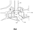
- Figure 4 schematically illustrates a radial cross sectional view of the exemplary mid-turbine frame 57 of Figure 2 along cross section B-B.
- Cross section B-B is drawn radially along a service line 130, and illustrates the torque box 140, and bearing support passage 150 surrounded by the torque box 140.
- the service line 130 includes a connection feature 170 including flanges 172 and a seal element 174.
- the connection feature 170 of the service line 130 connects to the bearing support passage 150 within the torque box 140.
- the service line connection feature 170 is sealed to the bearing support passage 150 via a seal element 174.
- the seal element 174 in the illustrated example is a piston seal. In alternative examples, any sealing element capable of sealing the service line 130 to the bearing support passage 150 can be utilized in place of the piston seal.
- the seal element 174 is disposed between an outward facing surface of an extension portion 173 of the service line connection feature 170 and an inward facing surface of the bearing support passage 150.
- the extension portion 173 extends into the bearing support passage 150.
- an inner frame case seal plate 176 Disposed radially outward of the service line connection feature 170 is an inner frame case seal plate 176.
- the inner frame case seal plate 176 is sealed to the inner frame case via a piston seal 178.
- alternative seal types capable of functioning in the mid-turbine frame environment could be utilized in place of the piston seal.
- the piston seal 178 prevents oil, and mid-turbine frame air, from outside of the inner frame case 120 from leaking into the torque box 140 through the interface between the connection feature 170 and the bearing support passage 150.
- the piston seal 178 also prevents any fluids within the torque box 140, from being passed out of the torque box 140 into the adjacent portions of the turbine engine.
- the bearing support passage 150 inside the torque box 140 provides oil to a bearing supported by the mid-turbine frame 57.
- the radially inward openings 152, 154 through which the bearing support passage 150 passes are similarly sealed at each opening 152, 154, preventing flow into and out of the torque box 140 at the radially inward portion of the bearing support passage 150.
- the torque box 140 is a sealed torque box, and fluids are not communicated into or out of the torque box 140.
- the above described configuration provides a configuration that is capable of minimizing the possibility for mid-turbine frame air from entering into the torque box 140.
- the possibility is further reduced by sealing the torque box from adjacent engine sections, and prevent the exchange of fluids between the torque box and adjacent engine portions including the cooling air flow being directed to the low pressure turbine.
- One of skill in the art, having the benefit of this disclosure will understand that while an ideal seal prevents all fluid exchange between both sides of the seal, practical seals will have a minimal amount of fluid exchange. Reference herein to minimized transfer of fluids across a seal is in reference to this practical reality.
Landscapes
- Engineering & Computer Science (AREA)
- Mechanical Engineering (AREA)
- General Engineering & Computer Science (AREA)
- Physics & Mathematics (AREA)
- Fluid Mechanics (AREA)
- Turbine Rotor Nozzle Sealing (AREA)
Claims (15)
- Mittelturbinenrahmen (57) für ein Gasturbinentriebwerk (20), umfassend:ein inneres Rahmengehäuse (120), das ein Lager oder Lagersystem konstruktionstechnisch trägt und einen abgedichteten Torsionskasten (140) definiert, wobei der Torsionskasten einen Hohlraum darstellt, der innerhalb des inneren Rahmengehäuses (120) definiert ist;eine Vielzahl von Speichen (110), die radial nach außen von dem inneren Rahmengehäuse (120) vorstehen, wobei die Vielzahl von Speichen (110) umfangsmäßig um das innere Rahmengehäuse (120) verteilt sind, eine Verbindung zwischen einem radial inneren Ende jeder der Speichen (110) und dem inneren Rahmengehäuse (120) abgedichtet ist, so dass eine Fluidübertragung in den Torsionskasten (140) an der Verbindung minimiert ist, jede der Speichen (110) einen Kühlkanal (112) umfasst, der sich von einem radial äußeren Ende der Speiche (110) in Richtung des inneren Rahmengehäuses (120) erstreckt, und jeder der Kühlkanäle (112) sich zu dem inneren Rahmengehäuse (120) erstreckt,dadurch gekennzeichnet, dass:eine radial innere Öffnung zwischen dem Kühlkanal (112) und dem Torsionskasten (140) an der Verbindung zwischen der Speiche und dem inneren Rahmengehäuse über eine Stopfendichtung (116) abgedichtet ist, wobei die Stopfendichtung (116) ein radial inneres Ende (115) des Kühlkanals (112) durch die Speiche (110) blockiert und die radial innere Öffnung des Kühlkanals (112) vollständig abdichtet; und dadurch, dassder Mittelturbinenrahmen (57) ferner mindestens eine Versorgungsleitung (130) umfasst, die über ein Verbindungsmerkmal (170) mit dem inneren Rahmengehäuse (120) verbunden ist, wobei das Verbindungsmerkmal (170) die Versorgungsleitung (130) mit einem entsprechenden Lagertragkanal (150) in dem Torsionskasten (140) verbindet, wobei der Torsionskasten (140) an jeder Öffnung für die Versorgungsleitung (130), die durch den Torsionskasten (140) verläuft, abgedichtet ist.
- Mittelturbinenrahmen (57) nach Anspruch 1, wobei jede der Speichen (110) ferner ein Umleitungsrohr (113) umfasst, das Kühlfluid, das durch den Kühlkanal (112) fließt, nach hinten leitet, so dass das Kühlfluid den Torsionskasten (140) umgeht.
- Mittelturbinenrahmen (57) nach einem der vorhergehenden Ansprüche, wobei das Verbindungsmerkmal (170) aufweist:einen Flanschabschnitt (172) und einen Erstreckungsabschnitt (173), wobei sich der Erstreckungsabschnitt (173) radial in den Lagertragkanal (150) erstreckt;eine Dichtungsplatte (176) radial außerhalb des Flanschabschnitts (172); undein Dichtungselement (178), das die Dichtungsplatte (176) an dem inneren Rahmengehäuse (120) abdichtet.
- Mittelturbinenrahmen (57) nach Anspruch 3, wobei das Dichtungselement (178), das die Dichtungsplatte (176) an dem inneren Rahmengehäuse (120) abdichtet, eine Kolbendichtung ist.
- Mittelturbinenrahmen (57) nach Anspruch 3 oder 4, ferner umfassend eine Versorgungsleitungsdichtung (174), die zwischen einer nach außen gewandten Fläche des Erstreckungsabschnitts und einer nach innen gewandten Fläche des Lagertragkanals (150) angeordnet ist.
- Mittelturbinenrahmen (57) nach einem der vorhergehenden Ansprüche, wobei der Lagertragkanal (150) mindestens eine erste Öffnung (152) aufweist, um Fluid aus dem Lagertragkanal (150) einer Komponente bereitzustellen, die radial innen von dem Mittelturbinenrahmen (57) angeordnet ist.
- Mittelturbinenrahmen (57) nach Anspruch 6, wobei die mindestens eine erste Öffnung (152) zu dem inneren Rahmengehäuse (57) hin abgedichtet ist, so dass Fluid, das durch die Öffnung (152) gelangt, nicht in den Torsionskasten (140) gelangt.
- Mittelturbinenrahmen (57) nach einem der vorhergehenden Ansprüche, wobei das innere Rahmengehäuse (120) so konfiguriert ist, dass die gesamte Kühlluft, die einem Triebwerkssegment benachbart zu dem inneren Rahmengehäuse (120) bereitgestellt wird, den Torsionskasten (140) umgeht.
- Verfahren, umfassend:Abdichten eines Torsionskastens (140), der in einem inneren Rahmengehäuse (120) definiert ist, so dass ein Durchfluss von Fluiden im Inneren des Torsionskastens (140) zu benachbarten Abschnitten eines Gasturbinentriebwerks (20) minimiert wird, indem ein Mittelturbinenrahmen (57) für ein Gasturbinentriebwerk (20) nach einem der vorhergehenden Ansprüche bereitgestellt wird; undAbdichten der Verbindung zwischen dem radial inneren Ende jeder der Speichen (110) und dem inneren Rahmengehäuse (120), indem der Mittelturbinenrahmen (57) so bereitgestellt wird, dass ein Durchfluss von Fluiden von dem Mittelturbinenrahmen (57) in den Torsionskasten (140) minimiert wird, und indem das radial innere Ende (115) jedes der Kühlkanäle (112) durch die Stopfendichtung (116) so abgedichtet wird, dass kein Fluid zwischen dem Torsionskasten (140) und den Kühlkanälen (112) ausgetauscht wird.
- Verfahren nach Anspruch 9, ferner umfassend Bereitstellen von Kühlluft an einen Turbinenabschnitt (28) des Gasturbinentriebwerks (20) durch den Mittelturbinenrahmen (57), wobei die Kühlluft den Torsionskasten (140) des Mittelturbinenrahmens (57) umgeht.
- Verfahren nach Anspruch 10, wobei das Bereitstellen von Kühlluft an den Turbinenabschnitt (28) durch den Mittelturbinenrahmen (57) unter Umgehung des Torsionskastens (140) ein Leiten von Kühlluft durch einen Kühlkanal (112) in mindestens einer der Speichen (110) und ein Umleiten der Kühlluft von der Speiche (110) über ein Umleitungsrohr (113) zu dem Turbinenabschnitt (28) umfasst.
- Verfahren nach einem der Ansprüche 9 bis 11, ferner umfassend Abdichten jeder Öffnung in dem Torsionskasten (140).
- Gasturbinentriebwerk (20), umfassend:einen primären Fluidströmungsweg, der mindestens teilweise durch einen Verdichterabschnitt (24), einen Brennkammerabschnitt (26) und einen Turbinenabschnitt (28) definiert ist; undeinen Mittelturbinenrahmen (57) nach Anspruch 1, der in dem Turbinenabschnitt (28) zwischen einem ersten Turbinenabschnitt (54) und einem zweiten Turbinenabschnitt (46) angeordnet ist, wobei der Mittelturbinenrahmen (57) ein Lager konstruktionstechnisch trägt, das mit dem ersten Turbinenabschnitt (54) verbunden ist, und dem zweiten Turbinenabschnitt (46) Kühlluft bereitstellt.
- Gasturbinentriebwerk (20) nach Anspruch 13, wobei die mindestens eine Versorgungsleitung (130) mit dem Lagertragkanal (150) in dem abgedichteten Torsionskasten (140) verbunden ist, so dass Fluid durch den Torsionskasten (140) und den Lagertragkanal (150) zu dem Lager gelangt.
- Gasturbinentriebwerk (20) nach Anspruch 14, wobei jede Öffnung in dem abgedichteten Torsionskasten (140) so abgedichtet ist, dass ein Fluidaustausch zwischen dem Torsionskasten (140) und Fluid außerhalb des Torsionskastens (140) minimiert wird.
Applications Claiming Priority (1)
| Application Number | Priority Date | Filing Date | Title |
|---|---|---|---|
| US14/695,323 US9885254B2 (en) | 2015-04-24 | 2015-04-24 | Mid turbine frame including a sealed torque box |
Publications (2)
| Publication Number | Publication Date |
|---|---|
| EP3085899A1 EP3085899A1 (de) | 2016-10-26 |
| EP3085899B1 true EP3085899B1 (de) | 2025-05-28 |
Family
ID=55808472
Family Applications (1)
| Application Number | Title | Priority Date | Filing Date |
|---|---|---|---|
| EP16166717.5A Active EP3085899B1 (de) | 2015-04-24 | 2016-04-22 | Mittelturbinenrahmen mit abgedichtetem torsionskasten für ein gasturbinentriebwerk |
Country Status (2)
| Country | Link |
|---|---|
| US (2) | US9885254B2 (de) |
| EP (1) | EP3085899B1 (de) |
Families Citing this family (8)
| Publication number | Priority date | Publication date | Assignee | Title |
|---|---|---|---|---|
| CA2936182C (en) | 2015-07-24 | 2023-08-15 | Pratt & Whitney Canada Corp. | Mid-turbine frame spoke cooling system and method |
| US10247035B2 (en) | 2015-07-24 | 2019-04-02 | Pratt & Whitney Canada Corp. | Spoke locking architecture |
| US10443449B2 (en) | 2015-07-24 | 2019-10-15 | Pratt & Whitney Canada Corp. | Spoke mounting arrangement |
| KR101882104B1 (ko) | 2016-12-20 | 2018-07-25 | 두산중공업 주식회사 | 가스터빈 |
| EP3385506B1 (de) | 2017-04-07 | 2019-10-30 | MTU Aero Engines GmbH | Dichtungsanordnung für eine gasturbine |
| US11118467B2 (en) * | 2017-07-26 | 2021-09-14 | General Electric Company | System and method for converting turbine cooling nozzle |
| US11346249B2 (en) * | 2019-03-05 | 2022-05-31 | Pratt & Whitney Canada Corp. | Gas turbine engine with feed pipe for bearing housing |
| CN110761855B (zh) * | 2019-10-11 | 2022-06-07 | 中国航发沈阳发动机研究所 | 一种燃气涡轮发动机后机匣 |
Citations (2)
| Publication number | Priority date | Publication date | Assignee | Title |
|---|---|---|---|---|
| EP3045671A1 (de) * | 2015-01-16 | 2016-07-20 | United Technologies Corporation | Kühlkanäle für einen mittelturbinenrahmen |
| EP3054101A1 (de) * | 2015-02-09 | 2016-08-10 | United Technologies Corporation | Kühlkanäle für einen mittelturbinenrahmen |
Family Cites Families (35)
| Publication number | Priority date | Publication date | Assignee | Title |
|---|---|---|---|---|
| US2919888A (en) * | 1957-04-17 | 1960-01-05 | United Aircraft Corp | Turbine bearing support |
| US3572733A (en) | 1969-01-02 | 1971-03-30 | Gen Electric | Shaft seal used in gas turbine engines |
| US4245951A (en) * | 1978-04-26 | 1981-01-20 | General Motors Corporation | Power turbine support |
| US4304522A (en) * | 1980-01-15 | 1981-12-08 | Pratt & Whitney Aircraft Of Canada Limited | Turbine bearing support |
| US4478551A (en) * | 1981-12-08 | 1984-10-23 | United Technologies Corporation | Turbine exhaust case design |
| US4987736A (en) * | 1988-12-14 | 1991-01-29 | General Electric Company | Lightweight gas turbine engine frame with free-floating heat shield |
| US5160251A (en) * | 1991-05-13 | 1992-11-03 | General Electric Company | Lightweight engine turbine bearing support assembly for withstanding radial and axial loads |
| JP3416447B2 (ja) * | 1997-03-11 | 2003-06-16 | 三菱重工業株式会社 | ガスタービンの翼冷却空気供給システム |
| US6102577A (en) * | 1998-10-13 | 2000-08-15 | Pratt & Whitney Canada Corp. | Isolated oil feed |
| US6099165A (en) * | 1999-01-19 | 2000-08-08 | Pratt & Whitney Canada Corp. | Soft bearing support |
| ITMI991208A1 (it) * | 1999-05-31 | 2000-12-01 | Nuovo Pignone Spa | Dispositivo per il posizionamento di ugelli di uno stadio statorico eper il raffreddamento di dischi rotorici in turbine a gas |
| US7278516B2 (en) * | 2004-03-09 | 2007-10-09 | Honeywell International, Inc. | Apparatus and method for bearing lubrication in turbine engines |
| US7195447B2 (en) | 2004-10-29 | 2007-03-27 | General Electric Company | Gas turbine engine and method of assembling same |
| US7797946B2 (en) * | 2006-12-06 | 2010-09-21 | United Technologies Corporation | Double U design for mid-turbine frame struts |
| US20110189000A1 (en) | 2007-05-01 | 2011-08-04 | General Electric Company | System for regulating a cooling fluid within a turbomachine |
| US8091371B2 (en) | 2008-11-28 | 2012-01-10 | Pratt & Whitney Canada Corp. | Mid turbine frame for gas turbine engine |
| US8061969B2 (en) | 2008-11-28 | 2011-11-22 | Pratt & Whitney Canada Corp. | Mid turbine frame system for gas turbine engine |
| US8177488B2 (en) * | 2008-11-29 | 2012-05-15 | General Electric Company | Integrated service tube and impingement baffle for a gas turbine engine |
| US20100275572A1 (en) * | 2009-04-30 | 2010-11-04 | Pratt & Whitney Canada Corp. | Oil line insulation system for mid turbine frame |
| US8371127B2 (en) | 2009-10-01 | 2013-02-12 | Pratt & Whitney Canada Corp. | Cooling air system for mid turbine frame |
| US8500392B2 (en) | 2009-10-01 | 2013-08-06 | Pratt & Whitney Canada Corp. | Sealing for vane segments |
| WO2011129724A1 (en) * | 2010-04-16 | 2011-10-20 | Volvo Aero Corporation | A strut, a gas turbine engine frame comprising the strut and a gas turbine engine comprising the frame |
| US20120011824A1 (en) * | 2010-07-16 | 2012-01-19 | United Technologies Corporation | Integral lubrication tube and nozzle combination |
| US9200536B2 (en) | 2011-10-17 | 2015-12-01 | United Technologies Corporation | Mid turbine frame (MTF) for a gas turbine engine |
| US8992173B2 (en) * | 2011-11-04 | 2015-03-31 | United Technologies Corporation | Tie-rod nut including a nut flange with a plurality of mounting apertures |
| US8979483B2 (en) * | 2011-11-07 | 2015-03-17 | United Technologies Corporation | Mid-turbine bearing support |
| US8944749B2 (en) | 2012-01-24 | 2015-02-03 | Pratt & Whitney Canada Corp. | Oil purge system for a mid turbine frame |
| US9347374B2 (en) | 2012-02-27 | 2016-05-24 | United Technologies Corporation | Gas turbine engine buffer cooling system |
| US9494052B2 (en) * | 2012-03-27 | 2016-11-15 | United Technologies Corporation | Dual-intent locator pin and removable plug for gas turbines |
| US9217371B2 (en) | 2012-07-13 | 2015-12-22 | United Technologies Corporation | Mid-turbine frame with tensioned spokes |
| US9587514B2 (en) * | 2012-07-13 | 2017-03-07 | United Technologies Corporation | Vane insertable tie rods with keyed connections |
| CA2881774C (en) | 2012-09-26 | 2017-10-24 | United Technologies Corporation | Seal assembly for a static structure of a gas turbine engine |
| EP3456943B1 (de) | 2012-09-28 | 2021-08-04 | Raytheon Technologies Corporation | Strömungsmessendes t-rohr mit geteilter zone |
| WO2014052007A1 (en) | 2012-09-28 | 2014-04-03 | United Technologies Corporation | Mid-turbine frame with fairing attachment |
| US11008890B2 (en) | 2014-11-25 | 2021-05-18 | Raytheon Technologies Corporation | Sealing interface for a case of a gas turbine engine |
-
2015
- 2015-04-24 US US14/695,323 patent/US9885254B2/en active Active
-
2016
- 2016-04-22 EP EP16166717.5A patent/EP3085899B1/de active Active
-
2017
- 2017-12-04 US US15/830,558 patent/US11118480B2/en active Active
Patent Citations (2)
| Publication number | Priority date | Publication date | Assignee | Title |
|---|---|---|---|---|
| EP3045671A1 (de) * | 2015-01-16 | 2016-07-20 | United Technologies Corporation | Kühlkanäle für einen mittelturbinenrahmen |
| EP3054101A1 (de) * | 2015-02-09 | 2016-08-10 | United Technologies Corporation | Kühlkanäle für einen mittelturbinenrahmen |
Also Published As
| Publication number | Publication date |
|---|---|
| US20160312659A1 (en) | 2016-10-27 |
| US20180087406A1 (en) | 2018-03-29 |
| EP3085899A1 (de) | 2016-10-26 |
| US11118480B2 (en) | 2021-09-14 |
| US9885254B2 (en) | 2018-02-06 |
Similar Documents
| Publication | Publication Date | Title |
|---|---|---|
| EP3085899B1 (de) | Mittelturbinenrahmen mit abgedichtetem torsionskasten für ein gasturbinentriebwerk | |
| US9932902B2 (en) | Turbine section support for a gas turbine engine | |
| US9163717B2 (en) | Multi-piece fluid manifold for gas turbine engine | |
| EP3056680B1 (de) | Leckageluftsysteme für turbomaschinen | |
| US11988146B2 (en) | Thermal management of a gas turbine engine shaft | |
| EP3084180B1 (de) | Übertragungslager für getriebefan | |
| EP3382156B1 (de) | Gasturbine mit gekühlter kühlluft für eine schaufelluftabdichtung durch eine aussenkammer | |
| EP3822459A1 (de) | Deckbandsegment mit kühlungsnut | |
| EP2993301B1 (de) | Struktur eines gasturbinentriebwerks, gasturbinentriebwerk und verfahren zum leiten eines kühlmittels durch einen strömungspfad in einem gasturbinentriebwerk | |
| EP2905427B1 (de) | Dichtungsanordnung für Gasturbinenmotor | |
| EP2985425B1 (de) | Messsystem für gasturbinenkühlflüssigkeit | |
| US11181004B2 (en) | Confinement of a rope seal about a passage using a backing plate | |
| EP3421720B1 (de) | Turbinenwelle und zugehöriges lufttransfersystem | |
| US11788468B1 (en) | Engine case leakage mitigation heat exchanger | |
| US11085313B2 (en) | System and method for transporting lubricant through a vane | |
| EP3754169B1 (de) | Hochdruckspaltregelungssystem für einen gasturbinenmotor | |
| US10823069B2 (en) | Internal heat exchanger system to cool gas turbine engine components |
Legal Events
| Date | Code | Title | Description |
|---|---|---|---|
| PUAI | Public reference made under article 153(3) epc to a published international application that has entered the european phase |
Free format text: ORIGINAL CODE: 0009012 |
|
| AK | Designated contracting states |
Kind code of ref document: A1 Designated state(s): AL AT BE BG CH CY CZ DE DK EE ES FI FR GB GR HR HU IE IS IT LI LT LU LV MC MK MT NL NO PL PT RO RS SE SI SK SM TR |
|
| AX | Request for extension of the european patent |
Extension state: BA ME |
|
| STAA | Information on the status of an ep patent application or granted ep patent |
Free format text: STATUS: THE APPLICATION HAS BEEN PUBLISHED |
|
| 17P | Request for examination filed |
Effective date: 20170426 |
|
| RBV | Designated contracting states (corrected) |
Designated state(s): AL AT BE BG CH CY CZ DE DK EE ES FI FR GB GR HR HU IE IS IT LI LT LU LV MC MK MT NL NO PL PT RO RS SE SI SK SM TR |
|
| STAA | Information on the status of an ep patent application or granted ep patent |
Free format text: STATUS: REQUEST FOR EXAMINATION WAS MADE |
|
| STAA | Information on the status of an ep patent application or granted ep patent |
Free format text: STATUS: EXAMINATION IS IN PROGRESS |
|
| 17Q | First examination report despatched |
Effective date: 20180806 |
|
| RAP1 | Party data changed (applicant data changed or rights of an application transferred) |
Owner name: RAYTHEON TECHNOLOGIES CORPORATION |
|
| RAP3 | Party data changed (applicant data changed or rights of an application transferred) |
Owner name: RTX CORPORATION |
|
| GRAP | Despatch of communication of intention to grant a patent |
Free format text: ORIGINAL CODE: EPIDOSNIGR1 |
|
| STAA | Information on the status of an ep patent application or granted ep patent |
Free format text: STATUS: GRANT OF PATENT IS INTENDED |
|
| INTG | Intention to grant announced |
Effective date: 20241206 |
|
| GRAS | Grant fee paid |
Free format text: ORIGINAL CODE: EPIDOSNIGR3 |
|
| GRAA | (expected) grant |
Free format text: ORIGINAL CODE: 0009210 |
|
| STAA | Information on the status of an ep patent application or granted ep patent |
Free format text: STATUS: THE PATENT HAS BEEN GRANTED |
|
| AK | Designated contracting states |
Kind code of ref document: B1 Designated state(s): AL AT BE BG CH CY CZ DE DK EE ES FI FR GB GR HR HU IE IS IT LI LT LU LV MC MK MT NL NO PL PT RO RS SE SI SK SM TR |
|
| REG | Reference to a national code |
Ref country code: GB Ref legal event code: FG4D |
|
| REG | Reference to a national code |
Ref country code: CH Ref legal event code: EP |
|
| REG | Reference to a national code |
Ref country code: IE Ref legal event code: FG4D Ref country code: DE Ref legal event code: R096 Ref document number: 602016092381 Country of ref document: DE |
|
| REG | Reference to a national code |
Ref country code: NL Ref legal event code: MP Effective date: 20250528 |
|
| PG25 | Lapsed in a contracting state [announced via postgrant information from national office to epo] |
Ref country code: ES Free format text: LAPSE BECAUSE OF FAILURE TO SUBMIT A TRANSLATION OF THE DESCRIPTION OR TO PAY THE FEE WITHIN THE PRESCRIBED TIME-LIMIT Effective date: 20250528 Ref country code: FI Free format text: LAPSE BECAUSE OF FAILURE TO SUBMIT A TRANSLATION OF THE DESCRIPTION OR TO PAY THE FEE WITHIN THE PRESCRIBED TIME-LIMIT Effective date: 20250528 |
|
| REG | Reference to a national code |
Ref country code: LT Ref legal event code: MG9D |
|
| PG25 | Lapsed in a contracting state [announced via postgrant information from national office to epo] |
Ref country code: GR Free format text: LAPSE BECAUSE OF FAILURE TO SUBMIT A TRANSLATION OF THE DESCRIPTION OR TO PAY THE FEE WITHIN THE PRESCRIBED TIME-LIMIT Effective date: 20250829 Ref country code: NO Free format text: LAPSE BECAUSE OF FAILURE TO SUBMIT A TRANSLATION OF THE DESCRIPTION OR TO PAY THE FEE WITHIN THE PRESCRIBED TIME-LIMIT Effective date: 20250828 |
|
| PG25 | Lapsed in a contracting state [announced via postgrant information from national office to epo] |
Ref country code: NL Free format text: LAPSE BECAUSE OF FAILURE TO SUBMIT A TRANSLATION OF THE DESCRIPTION OR TO PAY THE FEE WITHIN THE PRESCRIBED TIME-LIMIT Effective date: 20250528 Ref country code: PL Free format text: LAPSE BECAUSE OF FAILURE TO SUBMIT A TRANSLATION OF THE DESCRIPTION OR TO PAY THE FEE WITHIN THE PRESCRIBED TIME-LIMIT Effective date: 20250528 |
|
| PG25 | Lapsed in a contracting state [announced via postgrant information from national office to epo] |
Ref country code: BG Free format text: LAPSE BECAUSE OF FAILURE TO SUBMIT A TRANSLATION OF THE DESCRIPTION OR TO PAY THE FEE WITHIN THE PRESCRIBED TIME-LIMIT Effective date: 20250528 |
|
| PG25 | Lapsed in a contracting state [announced via postgrant information from national office to epo] |
Ref country code: HR Free format text: LAPSE BECAUSE OF FAILURE TO SUBMIT A TRANSLATION OF THE DESCRIPTION OR TO PAY THE FEE WITHIN THE PRESCRIBED TIME-LIMIT Effective date: 20250528 |
|
| PG25 | Lapsed in a contracting state [announced via postgrant information from national office to epo] |
Ref country code: RS Free format text: LAPSE BECAUSE OF FAILURE TO SUBMIT A TRANSLATION OF THE DESCRIPTION OR TO PAY THE FEE WITHIN THE PRESCRIBED TIME-LIMIT Effective date: 20250828 |
|
| PG25 | Lapsed in a contracting state [announced via postgrant information from national office to epo] |
Ref country code: IS Free format text: LAPSE BECAUSE OF FAILURE TO SUBMIT A TRANSLATION OF THE DESCRIPTION OR TO PAY THE FEE WITHIN THE PRESCRIBED TIME-LIMIT Effective date: 20250928 |
|
| PG25 | Lapsed in a contracting state [announced via postgrant information from national office to epo] |
Ref country code: LV Free format text: LAPSE BECAUSE OF FAILURE TO SUBMIT A TRANSLATION OF THE DESCRIPTION OR TO PAY THE FEE WITHIN THE PRESCRIBED TIME-LIMIT Effective date: 20250528 |
|
| REG | Reference to a national code |
Ref country code: AT Ref legal event code: MK05 Ref document number: 1798703 Country of ref document: AT Kind code of ref document: T Effective date: 20250528 |
|
| PG25 | Lapsed in a contracting state [announced via postgrant information from national office to epo] |
Ref country code: AT Free format text: LAPSE BECAUSE OF FAILURE TO SUBMIT A TRANSLATION OF THE DESCRIPTION OR TO PAY THE FEE WITHIN THE PRESCRIBED TIME-LIMIT Effective date: 20250528 Ref country code: SM Free format text: LAPSE BECAUSE OF FAILURE TO SUBMIT A TRANSLATION OF THE DESCRIPTION OR TO PAY THE FEE WITHIN THE PRESCRIBED TIME-LIMIT Effective date: 20250528 Ref country code: DK Free format text: LAPSE BECAUSE OF FAILURE TO SUBMIT A TRANSLATION OF THE DESCRIPTION OR TO PAY THE FEE WITHIN THE PRESCRIBED TIME-LIMIT Effective date: 20250528 |
|
| PG25 | Lapsed in a contracting state [announced via postgrant information from national office to epo] |
Ref country code: CZ Free format text: LAPSE BECAUSE OF FAILURE TO SUBMIT A TRANSLATION OF THE DESCRIPTION OR TO PAY THE FEE WITHIN THE PRESCRIBED TIME-LIMIT Effective date: 20250528 |
|
| PG25 | Lapsed in a contracting state [announced via postgrant information from national office to epo] |
Ref country code: EE Free format text: LAPSE BECAUSE OF FAILURE TO SUBMIT A TRANSLATION OF THE DESCRIPTION OR TO PAY THE FEE WITHIN THE PRESCRIBED TIME-LIMIT Effective date: 20250528 |
|
| PG25 | Lapsed in a contracting state [announced via postgrant information from national office to epo] |
Ref country code: SK Free format text: LAPSE BECAUSE OF FAILURE TO SUBMIT A TRANSLATION OF THE DESCRIPTION OR TO PAY THE FEE WITHIN THE PRESCRIBED TIME-LIMIT Effective date: 20250528 Ref country code: RO Free format text: LAPSE BECAUSE OF FAILURE TO SUBMIT A TRANSLATION OF THE DESCRIPTION OR TO PAY THE FEE WITHIN THE PRESCRIBED TIME-LIMIT Effective date: 20250528 |
|
| PG25 | Lapsed in a contracting state [announced via postgrant information from national office to epo] |
Ref country code: IT Free format text: LAPSE BECAUSE OF FAILURE TO SUBMIT A TRANSLATION OF THE DESCRIPTION OR TO PAY THE FEE WITHIN THE PRESCRIBED TIME-LIMIT Effective date: 20250528 |
|
| REG | Reference to a national code |
Ref country code: DE Ref legal event code: R097 Ref document number: 602016092381 Country of ref document: DE |
|
| PLBE | No opposition filed within time limit |
Free format text: ORIGINAL CODE: 0009261 |
|
| STAA | Information on the status of an ep patent application or granted ep patent |
Free format text: STATUS: NO OPPOSITION FILED WITHIN TIME LIMIT |
|
| PGFP | Annual fee paid to national office [announced via postgrant information from national office to epo] |
Ref country code: GB Payment date: 20260319 Year of fee payment: 11 |
|
| REG | Reference to a national code |
Ref country code: CH Ref legal event code: L10 Free format text: ST27 STATUS EVENT CODE: U-0-0-L10-L00 (AS PROVIDED BY THE NATIONAL OFFICE) Effective date: 20260409 |
|
| PGFP | Annual fee paid to national office [announced via postgrant information from national office to epo] |
Ref country code: FR Payment date: 20260320 Year of fee payment: 11 |