EP3085647A1 - Sucking disc - Google Patents
Sucking disc Download PDFInfo
- Publication number
- EP3085647A1 EP3085647A1 EP14861808.5A EP14861808A EP3085647A1 EP 3085647 A1 EP3085647 A1 EP 3085647A1 EP 14861808 A EP14861808 A EP 14861808A EP 3085647 A1 EP3085647 A1 EP 3085647A1
- Authority
- EP
- European Patent Office
- Prior art keywords
- sucking disc
- pads
- separator plate
- disc body
- periphery
- Prior art date
- Legal status (The legal status is an assumption and is not a legal conclusion. Google has not performed a legal analysis and makes no representation as to the accuracy of the status listed.)
- Granted
Links
Images


Classifications
-
- B—PERFORMING OPERATIONS; TRANSPORTING
- B25—HAND TOOLS; PORTABLE POWER-DRIVEN TOOLS; MANIPULATORS
- B25J—MANIPULATORS; CHAMBERS PROVIDED WITH MANIPULATION DEVICES
- B25J15/00—Gripping heads and other end effectors
- B25J15/06—Gripping heads and other end effectors with vacuum or magnetic holding means
- B25J15/0616—Gripping heads and other end effectors with vacuum or magnetic holding means with vacuum
-
- B—PERFORMING OPERATIONS; TRANSPORTING
- B65—CONVEYING; PACKING; STORING; HANDLING THIN OR FILAMENTARY MATERIAL
- B65G—TRANSPORT OR STORAGE DEVICES, e.g. CONVEYORS FOR LOADING OR TIPPING, SHOP CONVEYOR SYSTEMS OR PNEUMATIC TUBE CONVEYORS
- B65G47/00—Article or material-handling devices associated with conveyors; Methods employing such devices
- B65G47/74—Feeding, transfer, or discharging devices of particular kinds or types
- B65G47/90—Devices for picking-up and depositing articles or materials
- B65G47/91—Devices for picking-up and depositing articles or materials incorporating pneumatic, e.g. suction, grippers
- B65G47/911—Devices for picking-up and depositing articles or materials incorporating pneumatic, e.g. suction, grippers with air blasts producing partial vacuum
Definitions
- the present invention relates to a sucking disc.
- a mechanical clip tool typically has two or more splints which are capable of being opened and closed, so as to carry out a squeeze operation by forcedly squeezing the splints.
- the mechanical clip tool fails to pick up a soft sheet-shaped work piece (such as a slice of bread, a tomato slice or the like), and because there exists wear-out between various mechanical parts, the work load of routine maintenance is heavy.
- a rubber vacuum sucking disc has such advantages as simple structure and easy to repair and maintain, which is a pickup tool commonly used in a line of food production.
- To create a negative pressure in the inner chamber of the sucking disc by pumping the air out using a vacuum pump or a vacuum generator is the most common means.
- a quantity of air is sucked in due to the pressure difference when there is even a small gap around the edge of the sucking disc, and thus the suction force is greatly reduced.
- the problem is more serious especially if the work piece with a rough surface is absorbed, because the rubber sucking disc cannot fully fit into the surface of the work piece.
- a contaminant such as the residue or liquid may be sucked into the vacuum pipe of the sucking disc to result in a blockage.
- Patent publication No. CN3640313 disclosed a sucking disc (as shown in FIG. 2a and FIG. 2b ), wherein two tangential nozzles are disposed on the wall surface of the cylindrical cavity of the sucking disc, fluids are injected from the nozzles and flow along the surface wall of the cylindrical cavity so as to form a swirling flow, due to the centrifugal force of the swirling flow, a low pressure distribution inside the cavity is formed which is lower than the external pressure around the sucking disc, thus enabling a plate-like work piece under the sucking disc to be sucked and held.
- the technology has the following defects:
- the present invention provides a sucking disc, in which the roughness or softness of the surface of a work piece has less influence on the suction force.
- the pads are disposed and spaced at equal intervals on the periphery of the bottom surface of the sucking disc body.
- an annular separator plate is disposed under the sucking disc body and the pads are disposed between the annular separator plate and the sucking disc body, such that a fixed channel is formed between the periphery of the bottom surface of the sucking disc body and the annular separator plate, and the interior of the chamber of the sucking disc is in communication with the ambient.
- the fluids cannot flow into the gap between the work piece and the annual separator plate, such that the lower end surface of the annular separator plate is brought into full contact with the work piece, thus enabling enough friction to be formed in the horizontal direction to ensure that the work piece cannot slip down during the transportation of the work piece in the horizontal direction.
- a soft material such as rubber is attached to the lower end surface of the annular separator plate to obtain better friction effect.
- the design of the height of the pads namely, the height of the fixed channel is very important. It is found by analysis of experiments that, if the height of the pads is too small, very high pressure distribution is formed under the effect of viscous friction during the time that the fluids flow through the narrow fixed channel, and the lower pressure distribution inside the chamber may be shifted toward higher pressure distribution due to the very high pressure distribution, thereby making the suction force weaken; if the height of the pads is progressively increased, the effect of the viscous friction in the fixed channel is weaken, such that the high pressure distribution in the fixed channel can be reduced and the lower pressure distribution inside the chamber can be shifted downward, thereby increasing the suction force; however, if the height of the pads continue to be increased, it is found that the suction force will be weaken instead.
- a sucking disc includes a sucking disc body 1; there is a chamber 12 with a circular cross section inside the sucking disc body 1, and the chamber 12 has a closed end surface and an opening end surface, the opening end surface is formed to be an end surface for absorbing an object and tangential nozzles 11 are disposed on the wall surface of the chamber 12.
- the sucking disc further includes an annular separator plate 3 and pads 2; the pads 2 are disposed apart from each other on the periphery of the bottom surface of the sucking disc body 1 and the upper surface of the annular separator plate 3 is fixedly attached with the periphery of the bottom surface of the sucking disc body 1 via the pads 2; a partial area of the annular separator plate 3 is covered by the pads 2, a fixed channel from the annular separator plate 3 to the periphery of the bottom surface of the sucking disc body 1 is formed by the separations between the pads; and the interior of the chamber 12 is communicated with the ambient via the fixed channel.
- the pads 2 are disposed and spaced at equal intervals on the periphery of the bottom surface of the sucking disc body 1. In this embodiment, 4 pads are used.
- an annular separator plate is disposed under the sucking disc body and the pads are disposed between the annular separator plate and the sucking disc body, such that a fixed channel is formed between the periphery of the bottom surface of the sucking disc body and the annular separator plate, and the interior of the chamber of the sucking disc is in communication with the ambient.
- the fluids cannot flow into the gap between the work piece and the annual separator plate, such that the lower end surface of the annular separator plate is brought into full contact with the work piece, thus enabling enough friction to be formed in the horizontal direction to ensure that the work piece cannot slip down during the transportation of the work piece in the horizontal direction.
- a soft material such as rubber is attached to the lower end surface of the annular separator plate to obtain better friction effect.
- the content described in the embodiment of the present invention is merely an example of an implementation form of the invention concept.
- the protection range of the present invention shall not be considered to be limited to the particular form described in this embodiment.
- the protection range of the present invention should cover the technical measures and equivalents thereof that can be conceived by any person skilled in the art according to the invention concept.
Landscapes
- Engineering & Computer Science (AREA)
- Mechanical Engineering (AREA)
- Robotics (AREA)
- Manipulator (AREA)
- Hooks, Suction Cups, And Attachment By Adhesive Means (AREA)
Abstract
Description
- The present invention relates to a sucking disc.
- A mechanical clip tool typically has two or more splints which are capable of being opened and closed, so as to carry out a squeeze operation by forcedly squeezing the splints. However, the mechanical clip tool fails to pick up a soft sheet-shaped work piece (such as a slice of bread, a tomato slice or the like), and because there exists wear-out between various mechanical parts, the work load of routine maintenance is heavy.
- A rubber vacuum sucking disc has such advantages as simple structure and easy to repair and maintain, which is a pickup tool commonly used in a line of food production. To create a negative pressure in the inner chamber of the sucking disc by pumping the air out using a vacuum pump or a vacuum generator is the most common means. However, because there exists a large difference between the negative pressure inside the sucking disc and the atmosphere pressure outside the disc, a quantity of air is sucked in due to the pressure difference when there is even a small gap around the edge of the sucking disc, and thus the suction force is greatly reduced. The problem is more serious especially if the work piece with a rough surface is absorbed, because the rubber sucking disc cannot fully fit into the surface of the work piece. Moreover, in the case that some residue or liquid remains (for example in a line of food production), a contaminant such as the residue or liquid may be sucked into the vacuum pipe of the sucking disc to result in a blockage.
- Patent publication No.
CN3640313 disclosed a sucking disc (as shown inFIG. 2a andFIG. 2b ), wherein two tangential nozzles are disposed on the wall surface of the cylindrical cavity of the sucking disc, fluids are injected from the nozzles and flow along the surface wall of the cylindrical cavity so as to form a swirling flow, due to the centrifugal force of the swirling flow, a low pressure distribution inside the cavity is formed which is lower than the external pressure around the sucking disc, thus enabling a plate-like work piece under the sucking disc to be sucked and held. But the technology has the following defects: - 1. the fluids entered from the nozzles will be discharged via the lower portion of the sucking disc; therefore, the sucking disc is held apart from the work piece at an interval meanwhile the work piece is sucked by the sucking disc, and a gap is formed between the periphery of the bottom surface of the sucking disc and the work piece, resulting in the fluids flowing through the gap to be expelled. This may cause no contact between the sucking disc and the work piece, and therefore, the sucking disc cannot provide any friction in the horizontal direction. Without the friction in the horizontal direction, the work piece cannot be moved along with the sucking disc in the horizontal direction.
- 2. when the fluids flow through the gap between the periphery of the bottom surface of the sucking disc and the work piece, a distribution of higher pressure at the periphery than the ambient pressure is formed (see
FIG. 3 ) by the effect of stickiness. Because of such higher pressure distribution at the periphery of the bottom surface, not only a repelling force is exerted against the work piece, but also the low pressure distribution area inside the cavity is shifted toward the higher pressure distribution area, thus making the force of suction weaker. - 3. in the case that the surface of the work piece is rough or uneven, the flow resistance through the channel of the gap between the surface of the work piece and the periphery of the bottom surface of the sucking disc may increase; and if the roughness of the surface of the work piece is irregular, the flow resistance along the periphery is also irregular, that is, the flow resistance is larger in some places and smaller in others. As a result, a disorder occurs in the fluids while flowing through such channels (see
FIG. 4a and FIG. 4b ), thus resulting in sharp decrease of the suction force and unstable suction effect. It is found by studies that there is a correlation relationship between the pressure distribution along the periphery of the bottom surface and the lower pressure distribution inside the cavity of the sucking disc, that is, as the pressure distribution along the periphery becomes a disorder, the lower pressure distribution inside the cavity becomes a disorder too, thereby resulting in unstable suction force. Moreover, because of the rough surface of the work piece, the flow resistance of the fluids is increased, and the pressure distribution formed along the periphery of the bottom surface which is higher than the ambient pressure may continue to increase, and thus the repelling force against the work piece may be increased, while the lower pressure distribution inside the cavity may be shifted toward the higher pressure distribution. The factors eventually cause sharp decrease and instability of the suction force. - 4. if the work piece is made of a soft material, the work piece may deform under the effect of lower pressure inside the cavity, thereby resulting in sinking of the central portion of the work piece into the cavity. Such deformation may possibly cause a partial contact between the work piece and the sucking disc (see
FIG. 5 ). The fluids cannot flow through those places where the partial contact occurs, thereby resulting in serious asymmetry of the fluid discharge along the periphery and the occurrence of the disorder. The disorder of the fluid discharge may break the state of fluid whirling inside the cavity, thus resulting in sharp decrease of the suction force. - To overcome the disadvantages of the prior art sucking disc in which the suction force is weaken and unstable when a work piece with soft material or a rough or uneven surface is sucked, the present invention provides a sucking disc, in which the roughness or softness of the surface of a work piece has less influence on the suction force.
- The technical solution of the present invention is as followings:
- a sucking disc, including a sucking disc body; there is a chamber with a circular cross section inside the sucking disc body, and the chamber has a closed end surface and an opening end surface, the opening end surface is formed to be an end surface for absorbing an object and tangential nozzles are disposed on the wall surface of the chamber, characterized in that the sucking disc further includes an annular separator plate and some pads; pads are disposed apart from each other on the periphery of the bottom surface of the sucking disc body and the upper surface of the annular separator plate is fixedly attached with the periphery of the bottom surface of the sucking disc body via the pads; a partial area of the annular separator plate is covered by the pads, a fixed channel from the annular separator plate to the periphery of the bottom surface of the sucking disc body is formed by the separations between the pads; and the interior of the chamber is in communication with the ambient via the fixed channel.
- Further, the pads are disposed and spaced at equal intervals on the periphery of the bottom surface of the sucking disc body.
- According to the present invention, an annular separator plate is disposed under the sucking disc body and the pads are disposed between the annular separator plate and the sucking disc body, such that a fixed channel is formed between the periphery of the bottom surface of the sucking disc body and the annular separator plate, and the interior of the chamber of the sucking disc is in communication with the ambient. As a result, the fluids cannot flow into the gap between the work piece and the annual separator plate, such that the lower end surface of the annular separator plate is brought into full contact with the work piece, thus enabling enough friction to be formed in the horizontal direction to ensure that the work piece cannot slip down during the transportation of the work piece in the horizontal direction. According to the present invention, a soft material (such as rubber) is attached to the lower end surface of the annular separator plate to obtain better friction effect.
- In the above description, the design of the height of the pads, namely, the height of the fixed channel is very important. It is found by analysis of experiments that, if the height of the pads is too small, very high pressure distribution is formed under the effect of viscous friction during the time that the fluids flow through the narrow fixed channel, and the lower pressure distribution inside the chamber may be shifted toward higher pressure distribution due to the very high pressure distribution, thereby making the suction force weaken; if the height of the pads is progressively increased, the effect of the viscous friction in the fixed channel is weaken, such that the high pressure distribution in the fixed channel can be reduced and the lower pressure distribution inside the chamber can be shifted downward, thereby increasing the suction force; however, if the height of the pads continue to be increased, it is found that the suction force will be weaken instead. This is because too large fixed channel causes the fluids to flow into the channel without sufficient swirling, thereby making the swirling of the fluids inside the chamber weaken and thus resulting in decrease of the suction force. In the case that the given quantity of flow is fed from the tangential nozzles, the relationship between the height of the pads and the suction force is shown in
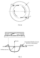
FIG. 6 , where as the height of the pads increases, a trend is presented that the suction force is early increased, and then decreased gradually. The relationship between the suction force and the height of the pads is represented as a curve, in which the maximum suction force is at the peak point of the curve, and the height of the pads corresponding to the maximum suction force is an optimum setting. - The beneficial effects of the present invention are reflected in the follows:
- 1. a direct and smooth channel is formed by the annular separator plate on the periphery of the bottom of the sucking disc body, through which the fluids inside the chamber can be evenly discharged. As a result, the fluids cannot flow into the gap between the work piece and the annual separator plate, such that the lower end surface of the annular separator plate is brought into full contact with the work piece, thus enabling enough friction to be formed in the horizontal direction to ensure that the work piece cannot slip down during the transportation of the work piece in the horizontal direction.
- 2. Since the height of the pads is set to the optimal value, a good swirling condition of the fluids is maintained while the high pressure distribution due to the effect of viscous friction is reduced as possible. Moreover, the annular separator plate is used to separate the downward repelling force resulting from the high pressure distribution due to the effect of viscous friction during the time that the fluids flow though the fixed channel, such that the repelling force may not be applied on the work piece.
- 3. a direct and smooth channel is formed by the annular separator plate on the periphery of the sucking disc body, through which the fluids flowing from the nozzles into the chamber can be evenly discharged. Even if a work piece with rough surface is sucked, the surface roughness of the work piece may not have any influence on the discharge of the fluids, thereby avoiding the problems of the fluid disorder occurring upon discharge of the fluids and reducing the influence of the surface roughness of the work piece on the suction force, and thus facilitating the stability of the suction force.
- 4. in the case of sucking a work piece of soft material, the work piece may deform under the effect of the suction force (see
FIG. 7 ). Even if the work piece is brought into contact with the annular separator plate due to the deformation, the channel for discharging the fluids may not be blocked; thereby the discharge of the fluids is not affected. The existence of the annular separator plate can ensure the smooth discharge of the fluids, and suppress the influence of the deformation of the work piece on the swirling flow inside the chamber as much as possible. -
-
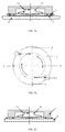
FIG. 1 a is a front sectional view of a sucking disc according to the present invention; -
FIG. 1b is a top view of a sucking disc according to the present invention; -
FIG. 2a is a front sectional view of a sucking disc disclosed in Patent publication No.CN3640313 ; -
FIG. 2b is a top view of a sucking disc disclosed in Patent publication No.CN3640313 ; -
FIG. 3 is a graph of a positive pressure distribution during the time that the fluids flow through between the work piece and the periphery of the bottom surface of the sucking disc without an annular separator plate; -
FIG. 4a is a schematic diagram of a sucking disc disclosed in Patent publication No.CN3640313 during the time that the work piece with rough or uneven surface is sucked; -
FIG. 4b is a partial enlarged view ofFIG. 4a (the disorder occurs during the time that the fluids flow through the gap); -
FIG. 5 is a schematic diagram of a sucking disc disclosed in Patent publication No.CN3640313 during the time that a soft object is sucked; -
FIG. 6 is a diagram showing the relationship between the height of the pads and the suction force; -
FIG. 7 is a schematic diagram of a sucking disc according to the present invention during the time that a soft object is sucked. - Referring to
FIG. 1 a andFIG. 1b , a sucking disc includes a suckingdisc body 1; there is achamber 12 with a circular cross section inside the suckingdisc body 1, and thechamber 12 has a closed end surface and an opening end surface, the opening end surface is formed to be an end surface for absorbing an object andtangential nozzles 11 are disposed on the wall surface of thechamber 12. The sucking disc further includes anannular separator plate 3 andpads 2; thepads 2 are disposed apart from each other on the periphery of the bottom surface of the suckingdisc body 1 and the upper surface of theannular separator plate 3 is fixedly attached with the periphery of the bottom surface of the suckingdisc body 1 via thepads 2; a partial area of theannular separator plate 3 is covered by thepads 2, a fixed channel from theannular separator plate 3 to the periphery of the bottom surface of the suckingdisc body 1 is formed by the separations between the pads; and the interior of thechamber 12 is communicated with the ambient via the fixed channel. - Further, the
pads 2 are disposed and spaced at equal intervals on the periphery of the bottom surface of the suckingdisc body 1. In this embodiment, 4 pads are used. - According to the present invention, an annular separator plate is disposed under the sucking disc body and the pads are disposed between the annular separator plate and the sucking disc body, such that a fixed channel is formed between the periphery of the bottom surface of the sucking disc body and the annular separator plate, and the interior of the chamber of the sucking disc is in communication with the ambient. As a result, the fluids cannot flow into the gap between the work piece and the annual separator plate, such that the lower end surface of the annular separator plate is brought into full contact with the work piece, thus enabling enough friction to be formed in the horizontal direction to ensure that the work piece cannot slip down during the transportation of the work piece in the horizontal direction. According to the present invention, a soft material (such as rubber) is attached to the lower end surface of the annular separator plate to obtain better friction effect.
- The content described in the embodiment of the present invention is merely an example of an implementation form of the invention concept. The protection range of the present invention shall not be considered to be limited to the particular form described in this embodiment. The protection range of the present invention should cover the technical measures and equivalents thereof that can be conceived by any person skilled in the art according to the invention concept.
Claims (2)
- A sucking disc, including a sucking disc body; there is a chamber with a circular cross section inside the sucking disc body, and the chamber has a closed end surface and an opening end surface, the opening end surface is formed to be an end surface for absorbing an object, and tangential nozzles are disposed on the wall surface of the chamber, characterized in that the sucking disc further includes an annular separator plate and some pads; pads are disposed apart from each other on the periphery of the bottom surface of the sucking disc body and the upper surface of the annular separator plate is fixedly attached with the periphery of the bottom surface of the sucking disc body via the pads; a partial area of the annular separator plate is covered by the pads, a fixed channel from the annular separator plate to the periphery of the bottom surface of the sucking disc body is formed by the separations between the pads; and the interior of the chamber is in communication with the ambient via the fixed channel.
- The sucking disc according to claim 1, wherein: pads are disposed and spaced at equal intervals on the periphery of the bottom surface of the sucking disc body.
Applications Claiming Priority (2)
| Application Number | Priority Date | Filing Date | Title |
|---|---|---|---|
| CN201310571285.XA CN104626174B (en) | 2013-11-13 | 2013-11-13 | Sucker |
| PCT/CN2014/090796 WO2015070742A1 (en) | 2013-11-13 | 2014-11-11 | Sucking disc |
Publications (3)
| Publication Number | Publication Date |
|---|---|
| EP3085647A1 true EP3085647A1 (en) | 2016-10-26 |
| EP3085647A4 EP3085647A4 (en) | 2017-10-25 |
| EP3085647B1 EP3085647B1 (en) | 2019-07-17 |
Family
ID=53056768
Family Applications (1)
| Application Number | Title | Priority Date | Filing Date |
|---|---|---|---|
| EP14861808.5A Not-in-force EP3085647B1 (en) | 2013-11-13 | 2014-11-11 | Sucking disc |
Country Status (5)
| Country | Link |
|---|---|
| US (1) | US20160288334A1 (en) |
| EP (1) | EP3085647B1 (en) |
| JP (1) | JP6123030B2 (en) |
| CN (1) | CN104626174B (en) |
| WO (1) | WO2015070742A1 (en) |
Cited By (1)
| Publication number | Priority date | Publication date | Assignee | Title |
|---|---|---|---|---|
| EP4317038A4 (en) * | 2021-04-01 | 2025-08-06 | Harmotec Co Ltd | TRANSPORT DEVICE, DISCHARGE RECTIFIER COVER AND APRON |
Families Citing this family (9)
| Publication number | Priority date | Publication date | Assignee | Title |
|---|---|---|---|---|
| JP2805428B2 (en) | 1993-02-10 | 1998-09-30 | 株式会社トヨックス | Watering nozzle with freeze absorber |
| JP6116629B2 (en) * | 2015-08-11 | 2017-04-19 | 株式会社ハーモテック | Suction device |
| JP6744630B2 (en) * | 2016-12-16 | 2020-08-19 | 株式会社ハーモテック | Baffle |
| JP6924488B2 (en) * | 2018-04-12 | 2021-08-25 | 株式会社ハーモテック | Swirling flow forming body |
| KR200492057Y1 (en) * | 2019-03-21 | 2020-07-29 | 최영진 | Board of Preventing Water Splashing for Sink |
| CN112388660A (en) * | 2019-08-19 | 2021-02-23 | 浙江大学 | Adsorption device |
| CN111997985B (en) * | 2020-07-29 | 2022-02-15 | 杭州孚亚科技有限公司 | Double-space adsorber |
| CN112943753B (en) * | 2021-04-09 | 2022-06-24 | 浙江大学 | Expanding radiation flow mechanism |
| CN117733630B (en) * | 2023-12-29 | 2025-04-25 | 宁波倍特瑞新能源科技有限公司 | Sucker type zinc block processing is with automatic unloading rotating mechanical arm that goes up |
Family Cites Families (16)
| Publication number | Priority date | Publication date | Assignee | Title |
|---|---|---|---|---|
| JPS5297376U (en) * | 1976-01-19 | 1977-07-21 | ||
| US5067762A (en) * | 1985-06-18 | 1991-11-26 | Hiroshi Akashi | Non-contact conveying device |
| JPH04365579A (en) * | 1991-06-14 | 1992-12-17 | Toshiba Corp | suction nozzle |
| US5882055A (en) * | 1996-02-12 | 1999-03-16 | Aetrium Incorporated | Probe for handling microchips |
| EP0902966A1 (en) * | 1996-05-31 | 1999-03-24 | IPEC Precision, Inc. | Non-contact holder for wafer-like articles |
| ATE211855T1 (en) * | 1999-04-28 | 2002-01-15 | Sez Semiconduct Equip Zubehoer | DEVICE AND METHOD FOR THE LIQUID TREATMENT OF DISK-SHAPED OBJECTS |
| US6402843B1 (en) * | 1999-12-07 | 2002-06-11 | Trusi Technologies, Llc | Non-contact workpiece holder |
| JP2007154933A (en) * | 2005-12-01 | 2007-06-21 | Kenwood Corp | Suction cup |
| CN3640313S (en) * | 2006-07-14 | 2007-05-02 | ||
| JP4243766B2 (en) * | 2006-10-02 | 2009-03-25 | Smc株式会社 | Non-contact transfer device |
| JP4740414B2 (en) * | 2007-04-24 | 2011-08-03 | 東京エレクトロン株式会社 | Substrate transfer device |
| JP2010052051A (en) * | 2008-08-26 | 2010-03-11 | Seiko Epson Corp | Bernoulli chuck, and suck-to-hold hand |
| CN201369321Y (en) * | 2009-03-23 | 2009-12-23 | 浙江大学 | Vortex non-contact silicon wafer holding device |
| JP2010253567A (en) * | 2009-04-21 | 2010-11-11 | Seiko Epson Corp | Suction holding hand, suction holding method, and transfer device |
| DE102011111768A1 (en) * | 2011-08-24 | 2013-02-28 | Robert Bosch Gmbh | Bernoulli gripper with full-surface workpiece system |
| US8904629B2 (en) * | 2012-03-09 | 2014-12-09 | LG CNS Co. Ltd. | Light-emitting diode (LED) wafer picker |
-
2013
- 2013-11-13 CN CN201310571285.XA patent/CN104626174B/en active Active
-
2014
- 2014-11-11 JP JP2016528899A patent/JP6123030B2/en active Active
- 2014-11-11 US US15/035,305 patent/US20160288334A1/en not_active Abandoned
- 2014-11-11 WO PCT/CN2014/090796 patent/WO2015070742A1/en not_active Ceased
- 2014-11-11 EP EP14861808.5A patent/EP3085647B1/en not_active Not-in-force
Cited By (1)
| Publication number | Priority date | Publication date | Assignee | Title |
|---|---|---|---|---|
| EP4317038A4 (en) * | 2021-04-01 | 2025-08-06 | Harmotec Co Ltd | TRANSPORT DEVICE, DISCHARGE RECTIFIER COVER AND APRON |
Also Published As
| Publication number | Publication date |
|---|---|
| CN104626174B (en) | 2016-06-15 |
| WO2015070742A1 (en) | 2015-05-21 |
| EP3085647A4 (en) | 2017-10-25 |
| EP3085647B1 (en) | 2019-07-17 |
| US20160288334A1 (en) | 2016-10-06 |
| CN104626174A (en) | 2015-05-20 |
| JP2017502216A (en) | 2017-01-19 |
| JP6123030B2 (en) | 2017-04-26 |
Similar Documents
| Publication | Publication Date | Title |
|---|---|---|
| US20160288334A1 (en) | Sucking disc | |
| US11577369B2 (en) | Suction device | |
| CN204387342U (en) | A kind of filling valve | |
| MX2019015845A (en) | Hydrocyclone separator. | |
| CN104482028B (en) | A kind of omnipotent negative pressure of vacuum sucker | |
| CN104385285B (en) | Adsorber | |
| JP6170411B2 (en) | Liquid container mounting pump | |
| CN207900013U (en) | Negative pressure waste suction diel | |
| CN207402796U (en) | Pressure holding structure of suction device | |
| CN104786229A (en) | Three-dimensional sucker | |
| CN207418275U (en) | New type of safe exhaust funnel | |
| CN210965160U (en) | Anti-suction device for experiment | |
| CN205134288U (en) | Be suitable for sluice breastwork structure of dominant discharge | |
| CN209210357U (en) | A buffer device for beverage production and filling | |
| CN205873237U (en) | Multi -point discharging ware discharge apparatus | |
| CN204746909U (en) | Ejecting device of unloading | |
| CN204355554U (en) | Air bubble quck-opening valve | |
| CN218468337U (en) | Safety valve sealing structure | |
| CN204664837U (en) | Oil can | |
| CN104590700B (en) | Novel safety and environment-friendly type spray cover | |
| CN202681626U (en) | An anti-blocking nut for the end of a pressure cooker exhaust pipe | |
| CN207985923U (en) | A kind of modified ribbon conveyer chute | |
| CN202786325U (en) | Anti-blocking vacuum charging device of vacuum oxygen blowing furnace | |
| CN208245052U (en) | A kind of nozzle attachment base | |
| ITUB20150622A1 (en) | Degassing pump |
Legal Events
| Date | Code | Title | Description |
|---|---|---|---|
| PUAI | Public reference made under article 153(3) epc to a published international application that has entered the european phase |
Free format text: ORIGINAL CODE: 0009012 |
|
| 17P | Request for examination filed |
Effective date: 20160809 |
|
| AK | Designated contracting states |
Kind code of ref document: A1 Designated state(s): AL AT BE BG CH CY CZ DE DK EE ES FI FR GB GR HR HU IE IS IT LI LT LU LV MC MK MT NL NO PL PT RO RS SE SI SK SM TR |
|
| AX | Request for extension of the european patent |
Extension state: BA ME |
|
| DAX | Request for extension of the european patent (deleted) | ||
| RIN1 | Information on inventor provided before grant (corrected) |
Inventor name: LI, XIN |
|
| A4 | Supplementary search report drawn up and despatched |
Effective date: 20170927 |
|
| RIC1 | Information provided on ipc code assigned before grant |
Ipc: B65G 47/91 20060101AFI20170921BHEP Ipc: B25J 15/06 20060101ALI20170921BHEP |
|
| STAA | Information on the status of an ep patent application or granted ep patent |
Free format text: STATUS: EXAMINATION IS IN PROGRESS |
|
| 17Q | First examination report despatched |
Effective date: 20180718 |
|
| GRAP | Despatch of communication of intention to grant a patent |
Free format text: ORIGINAL CODE: EPIDOSNIGR1 |
|
| STAA | Information on the status of an ep patent application or granted ep patent |
Free format text: STATUS: GRANT OF PATENT IS INTENDED |
|
| INTG | Intention to grant announced |
Effective date: 20190131 |
|
| GRAS | Grant fee paid |
Free format text: ORIGINAL CODE: EPIDOSNIGR3 |
|
| GRAA | (expected) grant |
Free format text: ORIGINAL CODE: 0009210 |
|
| STAA | Information on the status of an ep patent application or granted ep patent |
Free format text: STATUS: THE PATENT HAS BEEN GRANTED |
|
| AK | Designated contracting states |
Kind code of ref document: B1 Designated state(s): AL AT BE BG CH CY CZ DE DK EE ES FI FR GB GR HR HU IE IS IT LI LT LU LV MC MK MT NL NO PL PT RO RS SE SI SK SM TR |
|
| REG | Reference to a national code |
Ref country code: GB Ref legal event code: FG4D |
|
| REG | Reference to a national code |
Ref country code: CH Ref legal event code: EP |
|
| REG | Reference to a national code |
Ref country code: IE Ref legal event code: FG4D |
|
| REG | Reference to a national code |
Ref country code: DE Ref legal event code: R096 Ref document number: 602014050268 Country of ref document: DE |
|
| REG | Reference to a national code |
Ref country code: AT Ref legal event code: REF Ref document number: 1155674 Country of ref document: AT Kind code of ref document: T Effective date: 20190815 |
|
| REG | Reference to a national code |
Ref country code: NL Ref legal event code: MP Effective date: 20190717 |
|
| REG | Reference to a national code |
Ref country code: LT Ref legal event code: MG4D |
|
| REG | Reference to a national code |
Ref country code: AT Ref legal event code: MK05 Ref document number: 1155674 Country of ref document: AT Kind code of ref document: T Effective date: 20190717 |
|
| PG25 | Lapsed in a contracting state [announced via postgrant information from national office to epo] |
Ref country code: FI Free format text: LAPSE BECAUSE OF FAILURE TO SUBMIT A TRANSLATION OF THE DESCRIPTION OR TO PAY THE FEE WITHIN THE PRESCRIBED TIME-LIMIT Effective date: 20190717 Ref country code: SE Free format text: LAPSE BECAUSE OF FAILURE TO SUBMIT A TRANSLATION OF THE DESCRIPTION OR TO PAY THE FEE WITHIN THE PRESCRIBED TIME-LIMIT Effective date: 20190717 Ref country code: PT Free format text: LAPSE BECAUSE OF FAILURE TO SUBMIT A TRANSLATION OF THE DESCRIPTION OR TO PAY THE FEE WITHIN THE PRESCRIBED TIME-LIMIT Effective date: 20191118 Ref country code: HR Free format text: LAPSE BECAUSE OF FAILURE TO SUBMIT A TRANSLATION OF THE DESCRIPTION OR TO PAY THE FEE WITHIN THE PRESCRIBED TIME-LIMIT Effective date: 20190717 Ref country code: NL Free format text: LAPSE BECAUSE OF FAILURE TO SUBMIT A TRANSLATION OF THE DESCRIPTION OR TO PAY THE FEE WITHIN THE PRESCRIBED TIME-LIMIT Effective date: 20190717 Ref country code: AT Free format text: LAPSE BECAUSE OF FAILURE TO SUBMIT A TRANSLATION OF THE DESCRIPTION OR TO PAY THE FEE WITHIN THE PRESCRIBED TIME-LIMIT Effective date: 20190717 Ref country code: LT Free format text: LAPSE BECAUSE OF FAILURE TO SUBMIT A TRANSLATION OF THE DESCRIPTION OR TO PAY THE FEE WITHIN THE PRESCRIBED TIME-LIMIT Effective date: 20190717 Ref country code: NO Free format text: LAPSE BECAUSE OF FAILURE TO SUBMIT A TRANSLATION OF THE DESCRIPTION OR TO PAY THE FEE WITHIN THE PRESCRIBED TIME-LIMIT Effective date: 20191017 Ref country code: BG Free format text: LAPSE BECAUSE OF FAILURE TO SUBMIT A TRANSLATION OF THE DESCRIPTION OR TO PAY THE FEE WITHIN THE PRESCRIBED TIME-LIMIT Effective date: 20191017 |
|
| PG25 | Lapsed in a contracting state [announced via postgrant information from national office to epo] |
Ref country code: AL Free format text: LAPSE BECAUSE OF FAILURE TO SUBMIT A TRANSLATION OF THE DESCRIPTION OR TO PAY THE FEE WITHIN THE PRESCRIBED TIME-LIMIT Effective date: 20190717 Ref country code: ES Free format text: LAPSE BECAUSE OF FAILURE TO SUBMIT A TRANSLATION OF THE DESCRIPTION OR TO PAY THE FEE WITHIN THE PRESCRIBED TIME-LIMIT Effective date: 20190717 Ref country code: RS Free format text: LAPSE BECAUSE OF FAILURE TO SUBMIT A TRANSLATION OF THE DESCRIPTION OR TO PAY THE FEE WITHIN THE PRESCRIBED TIME-LIMIT Effective date: 20190717 Ref country code: LV Free format text: LAPSE BECAUSE OF FAILURE TO SUBMIT A TRANSLATION OF THE DESCRIPTION OR TO PAY THE FEE WITHIN THE PRESCRIBED TIME-LIMIT Effective date: 20190717 Ref country code: GR Free format text: LAPSE BECAUSE OF FAILURE TO SUBMIT A TRANSLATION OF THE DESCRIPTION OR TO PAY THE FEE WITHIN THE PRESCRIBED TIME-LIMIT Effective date: 20191018 Ref country code: IS Free format text: LAPSE BECAUSE OF FAILURE TO SUBMIT A TRANSLATION OF THE DESCRIPTION OR TO PAY THE FEE WITHIN THE PRESCRIBED TIME-LIMIT Effective date: 20191117 |
|
| PG25 | Lapsed in a contracting state [announced via postgrant information from national office to epo] |
Ref country code: TR Free format text: LAPSE BECAUSE OF FAILURE TO SUBMIT A TRANSLATION OF THE DESCRIPTION OR TO PAY THE FEE WITHIN THE PRESCRIBED TIME-LIMIT Effective date: 20190717 |
|
| PG25 | Lapsed in a contracting state [announced via postgrant information from national office to epo] |
Ref country code: IT Free format text: LAPSE BECAUSE OF FAILURE TO SUBMIT A TRANSLATION OF THE DESCRIPTION OR TO PAY THE FEE WITHIN THE PRESCRIBED TIME-LIMIT Effective date: 20190717 Ref country code: RO Free format text: LAPSE BECAUSE OF FAILURE TO SUBMIT A TRANSLATION OF THE DESCRIPTION OR TO PAY THE FEE WITHIN THE PRESCRIBED TIME-LIMIT Effective date: 20190717 Ref country code: PL Free format text: LAPSE BECAUSE OF FAILURE TO SUBMIT A TRANSLATION OF THE DESCRIPTION OR TO PAY THE FEE WITHIN THE PRESCRIBED TIME-LIMIT Effective date: 20190717 Ref country code: EE Free format text: LAPSE BECAUSE OF FAILURE TO SUBMIT A TRANSLATION OF THE DESCRIPTION OR TO PAY THE FEE WITHIN THE PRESCRIBED TIME-LIMIT Effective date: 20190717 Ref country code: DK Free format text: LAPSE BECAUSE OF FAILURE TO SUBMIT A TRANSLATION OF THE DESCRIPTION OR TO PAY THE FEE WITHIN THE PRESCRIBED TIME-LIMIT Effective date: 20190717 |
|
| PG25 | Lapsed in a contracting state [announced via postgrant information from national office to epo] |
Ref country code: CZ Free format text: LAPSE BECAUSE OF FAILURE TO SUBMIT A TRANSLATION OF THE DESCRIPTION OR TO PAY THE FEE WITHIN THE PRESCRIBED TIME-LIMIT Effective date: 20190717 Ref country code: SK Free format text: LAPSE BECAUSE OF FAILURE TO SUBMIT A TRANSLATION OF THE DESCRIPTION OR TO PAY THE FEE WITHIN THE PRESCRIBED TIME-LIMIT Effective date: 20190717 Ref country code: IS Free format text: LAPSE BECAUSE OF FAILURE TO SUBMIT A TRANSLATION OF THE DESCRIPTION OR TO PAY THE FEE WITHIN THE PRESCRIBED TIME-LIMIT Effective date: 20200224 Ref country code: SM Free format text: LAPSE BECAUSE OF FAILURE TO SUBMIT A TRANSLATION OF THE DESCRIPTION OR TO PAY THE FEE WITHIN THE PRESCRIBED TIME-LIMIT Effective date: 20190717 |
|
| REG | Reference to a national code |
Ref country code: DE Ref legal event code: R097 Ref document number: 602014050268 Country of ref document: DE |
|
| REG | Reference to a national code |
Ref country code: CH Ref legal event code: PL |
|
| PLBE | No opposition filed within time limit |
Free format text: ORIGINAL CODE: 0009261 |
|
| STAA | Information on the status of an ep patent application or granted ep patent |
Free format text: STATUS: NO OPPOSITION FILED WITHIN TIME LIMIT |
|
| PG2D | Information on lapse in contracting state deleted |
Ref country code: IS |
|
| PG25 | Lapsed in a contracting state [announced via postgrant information from national office to epo] |
Ref country code: LI Free format text: LAPSE BECAUSE OF NON-PAYMENT OF DUE FEES Effective date: 20191130 Ref country code: MC Free format text: LAPSE BECAUSE OF FAILURE TO SUBMIT A TRANSLATION OF THE DESCRIPTION OR TO PAY THE FEE WITHIN THE PRESCRIBED TIME-LIMIT Effective date: 20190717 Ref country code: CH Free format text: LAPSE BECAUSE OF NON-PAYMENT OF DUE FEES Effective date: 20191130 Ref country code: LU Free format text: LAPSE BECAUSE OF NON-PAYMENT OF DUE FEES Effective date: 20191111 |
|
| 26N | No opposition filed |
Effective date: 20200603 |
|
| REG | Reference to a national code |
Ref country code: BE Ref legal event code: MM Effective date: 20191130 |
|
| PG25 | Lapsed in a contracting state [announced via postgrant information from national office to epo] |
Ref country code: SI Free format text: LAPSE BECAUSE OF FAILURE TO SUBMIT A TRANSLATION OF THE DESCRIPTION OR TO PAY THE FEE WITHIN THE PRESCRIBED TIME-LIMIT Effective date: 20190717 |
|
| GBPC | Gb: european patent ceased through non-payment of renewal fee |
Effective date: 20191111 |
|
| PG25 | Lapsed in a contracting state [announced via postgrant information from national office to epo] |
Ref country code: FR Free format text: LAPSE BECAUSE OF NON-PAYMENT OF DUE FEES Effective date: 20191130 Ref country code: GB Free format text: LAPSE BECAUSE OF NON-PAYMENT OF DUE FEES Effective date: 20191111 Ref country code: IE Free format text: LAPSE BECAUSE OF NON-PAYMENT OF DUE FEES Effective date: 20191111 |
|
| PG25 | Lapsed in a contracting state [announced via postgrant information from national office to epo] |
Ref country code: BE Free format text: LAPSE BECAUSE OF NON-PAYMENT OF DUE FEES Effective date: 20191130 |
|
| PG25 | Lapsed in a contracting state [announced via postgrant information from national office to epo] |
Ref country code: CY Free format text: LAPSE BECAUSE OF FAILURE TO SUBMIT A TRANSLATION OF THE DESCRIPTION OR TO PAY THE FEE WITHIN THE PRESCRIBED TIME-LIMIT Effective date: 20190717 |
|
| PG25 | Lapsed in a contracting state [announced via postgrant information from national office to epo] |
Ref country code: HU Free format text: LAPSE BECAUSE OF FAILURE TO SUBMIT A TRANSLATION OF THE DESCRIPTION OR TO PAY THE FEE WITHIN THE PRESCRIBED TIME-LIMIT; INVALID AB INITIO Effective date: 20141111 Ref country code: MT Free format text: LAPSE BECAUSE OF FAILURE TO SUBMIT A TRANSLATION OF THE DESCRIPTION OR TO PAY THE FEE WITHIN THE PRESCRIBED TIME-LIMIT Effective date: 20190717 |
|
| PG25 | Lapsed in a contracting state [announced via postgrant information from national office to epo] |
Ref country code: MK Free format text: LAPSE BECAUSE OF FAILURE TO SUBMIT A TRANSLATION OF THE DESCRIPTION OR TO PAY THE FEE WITHIN THE PRESCRIBED TIME-LIMIT Effective date: 20190717 |
|
| REG | Reference to a national code |
Ref country code: DE Ref legal event code: R082 Ref document number: 602014050268 Country of ref document: DE Representative=s name: SUN, YIMING, M.SC. DIPL. SC. POL. UNIV., DE |
|
| PGFP | Annual fee paid to national office [announced via postgrant information from national office to epo] |
Ref country code: DE Payment date: 20231129 Year of fee payment: 10 |
|
| REG | Reference to a national code |
Ref country code: DE Ref legal event code: R119 Ref document number: 602014050268 Country of ref document: DE |
|
| PG25 | Lapsed in a contracting state [announced via postgrant information from national office to epo] |
Ref country code: DE Free format text: LAPSE BECAUSE OF NON-PAYMENT OF DUE FEES Effective date: 20250603 |