EP3085594A2 - Vehicle engine activation control system - Google Patents
Vehicle engine activation control system Download PDFInfo
- Publication number
- EP3085594A2 EP3085594A2 EP16166694.6A EP16166694A EP3085594A2 EP 3085594 A2 EP3085594 A2 EP 3085594A2 EP 16166694 A EP16166694 A EP 16166694A EP 3085594 A2 EP3085594 A2 EP 3085594A2
- Authority
- EP
- European Patent Office
- Prior art keywords
- engine
- release
- request
- epb
- reactivation
- Prior art date
- Legal status (The legal status is an assumption and is not a legal conclusion. Google has not performed a legal analysis and makes no representation as to the accuracy of the status listed.)
- Withdrawn
Links
- 230000004913 activation Effects 0.000 title claims abstract description 17
- 230000007420 reactivation Effects 0.000 claims abstract description 73
- 230000004044 response Effects 0.000 claims abstract description 25
- 239000007858 starting material Substances 0.000 claims abstract description 25
- 238000000034 method Methods 0.000 description 57
- 230000008569 process Effects 0.000 description 57
- 230000005856 abnormality Effects 0.000 description 7
- 230000007246 mechanism Effects 0.000 description 5
- 239000000446 fuel Substances 0.000 description 3
- 230000008901 benefit Effects 0.000 description 2
- 230000005540 biological transmission Effects 0.000 description 2
- 238000004378 air conditioning Methods 0.000 description 1
- 230000008859 change Effects 0.000 description 1
- 238000010586 diagram Methods 0.000 description 1
- 230000014509 gene expression Effects 0.000 description 1
- 230000004048 modification Effects 0.000 description 1
- 238000012986 modification Methods 0.000 description 1
- 230000007935 neutral effect Effects 0.000 description 1
Images



Classifications
-
- B—PERFORMING OPERATIONS; TRANSPORTING
- B60—VEHICLES IN GENERAL
- B60W—CONJOINT CONTROL OF VEHICLE SUB-UNITS OF DIFFERENT TYPE OR DIFFERENT FUNCTION; CONTROL SYSTEMS SPECIALLY ADAPTED FOR HYBRID VEHICLES; ROAD VEHICLE DRIVE CONTROL SYSTEMS FOR PURPOSES NOT RELATED TO THE CONTROL OF A PARTICULAR SUB-UNIT
- B60W10/00—Conjoint control of vehicle sub-units of different type or different function
- B60W10/18—Conjoint control of vehicle sub-units of different type or different function including control of braking systems
- B60W10/182—Conjoint control of vehicle sub-units of different type or different function including control of braking systems including control of parking brakes
-
- F—MECHANICAL ENGINEERING; LIGHTING; HEATING; WEAPONS; BLASTING
- F02—COMBUSTION ENGINES; HOT-GAS OR COMBUSTION-PRODUCT ENGINE PLANTS
- F02D—CONTROLLING COMBUSTION ENGINES
- F02D29/00—Controlling engines, such controlling being peculiar to the devices driven thereby, the devices being other than parts or accessories essential to engine operation, e.g. controlling of engines by signals external thereto
- F02D29/02—Controlling engines, such controlling being peculiar to the devices driven thereby, the devices being other than parts or accessories essential to engine operation, e.g. controlling of engines by signals external thereto peculiar to engines driving vehicles; peculiar to engines driving variable pitch propellers
-
- B—PERFORMING OPERATIONS; TRANSPORTING
- B60—VEHICLES IN GENERAL
- B60T—VEHICLE BRAKE CONTROL SYSTEMS OR PARTS THEREOF; BRAKE CONTROL SYSTEMS OR PARTS THEREOF, IN GENERAL; ARRANGEMENT OF BRAKING ELEMENTS ON VEHICLES IN GENERAL; PORTABLE DEVICES FOR PREVENTING UNWANTED MOVEMENT OF VEHICLES; VEHICLE MODIFICATIONS TO FACILITATE COOLING OF BRAKES
- B60T13/00—Transmitting braking action from initiating means to ultimate brake actuator with power assistance or drive; Brake systems incorporating such transmitting means, e.g. air-pressure brake systems
- B60T13/74—Transmitting braking action from initiating means to ultimate brake actuator with power assistance or drive; Brake systems incorporating such transmitting means, e.g. air-pressure brake systems with electrical assistance or drive
-
- B—PERFORMING OPERATIONS; TRANSPORTING
- B60—VEHICLES IN GENERAL
- B60T—VEHICLE BRAKE CONTROL SYSTEMS OR PARTS THEREOF; BRAKE CONTROL SYSTEMS OR PARTS THEREOF, IN GENERAL; ARRANGEMENT OF BRAKING ELEMENTS ON VEHICLES IN GENERAL; PORTABLE DEVICES FOR PREVENTING UNWANTED MOVEMENT OF VEHICLES; VEHICLE MODIFICATIONS TO FACILITATE COOLING OF BRAKES
- B60T13/00—Transmitting braking action from initiating means to ultimate brake actuator with power assistance or drive; Brake systems incorporating such transmitting means, e.g. air-pressure brake systems
- B60T13/74—Transmitting braking action from initiating means to ultimate brake actuator with power assistance or drive; Brake systems incorporating such transmitting means, e.g. air-pressure brake systems with electrical assistance or drive
- B60T13/746—Transmitting braking action from initiating means to ultimate brake actuator with power assistance or drive; Brake systems incorporating such transmitting means, e.g. air-pressure brake systems with electrical assistance or drive and mechanical transmission of the braking action
-
- B—PERFORMING OPERATIONS; TRANSPORTING
- B60—VEHICLES IN GENERAL
- B60T—VEHICLE BRAKE CONTROL SYSTEMS OR PARTS THEREOF; BRAKE CONTROL SYSTEMS OR PARTS THEREOF, IN GENERAL; ARRANGEMENT OF BRAKING ELEMENTS ON VEHICLES IN GENERAL; PORTABLE DEVICES FOR PREVENTING UNWANTED MOVEMENT OF VEHICLES; VEHICLE MODIFICATIONS TO FACILITATE COOLING OF BRAKES
- B60T7/00—Brake-action initiating means
- B60T7/02—Brake-action initiating means for personal initiation
- B60T7/08—Brake-action initiating means for personal initiation hand actuated
- B60T7/10—Disposition of hand control
- B60T7/107—Disposition of hand control with electrical power assistance
-
- B—PERFORMING OPERATIONS; TRANSPORTING
- B60—VEHICLES IN GENERAL
- B60T—VEHICLE BRAKE CONTROL SYSTEMS OR PARTS THEREOF; BRAKE CONTROL SYSTEMS OR PARTS THEREOF, IN GENERAL; ARRANGEMENT OF BRAKING ELEMENTS ON VEHICLES IN GENERAL; PORTABLE DEVICES FOR PREVENTING UNWANTED MOVEMENT OF VEHICLES; VEHICLE MODIFICATIONS TO FACILITATE COOLING OF BRAKES
- B60T7/00—Brake-action initiating means
- B60T7/12—Brake-action initiating means for automatic initiation; for initiation not subject to will of driver or passenger
- B60T7/122—Brake-action initiating means for automatic initiation; for initiation not subject to will of driver or passenger for locking of reverse movement
-
- F—MECHANICAL ENGINEERING; LIGHTING; HEATING; WEAPONS; BLASTING
- F02—COMBUSTION ENGINES; HOT-GAS OR COMBUSTION-PRODUCT ENGINE PLANTS
- F02D—CONTROLLING COMBUSTION ENGINES
- F02D11/00—Arrangements for, or adaptations to, non-automatic engine control initiation means, e.g. operator initiated
- F02D11/06—Arrangements for, or adaptations to, non-automatic engine control initiation means, e.g. operator initiated characterised by non-mechanical control linkages, e.g. fluid control linkages or by control linkages with power drive or assistance
- F02D11/10—Arrangements for, or adaptations to, non-automatic engine control initiation means, e.g. operator initiated characterised by non-mechanical control linkages, e.g. fluid control linkages or by control linkages with power drive or assistance of the electric type
-
- F—MECHANICAL ENGINEERING; LIGHTING; HEATING; WEAPONS; BLASTING
- F02—COMBUSTION ENGINES; HOT-GAS OR COMBUSTION-PRODUCT ENGINE PLANTS
- F02D—CONTROLLING COMBUSTION ENGINES
- F02D17/00—Controlling engines by cutting out individual cylinders; Rendering engines inoperative or idling
- F02D17/04—Controlling engines by cutting out individual cylinders; Rendering engines inoperative or idling rendering engines inoperative or idling, e.g. caused by abnormal conditions
-
- F—MECHANICAL ENGINEERING; LIGHTING; HEATING; WEAPONS; BLASTING
- F02—COMBUSTION ENGINES; HOT-GAS OR COMBUSTION-PRODUCT ENGINE PLANTS
- F02N—STARTING OF COMBUSTION ENGINES; STARTING AIDS FOR SUCH ENGINES, NOT OTHERWISE PROVIDED FOR
- F02N11/00—Starting of engines by means of electric motors
- F02N11/08—Circuits specially adapted for starting of engines
- F02N11/0814—Circuits specially adapted for starting of engines comprising means for controlling automatic idle-start-stop
- F02N11/0818—Conditions for starting or stopping the engine or for deactivating the idle-start-stop mode
- F02N11/0829—Conditions for starting or stopping the engine or for deactivating the idle-start-stop mode related to special engine control, e.g. giving priority to engine warming-up or learning
-
- F—MECHANICAL ENGINEERING; LIGHTING; HEATING; WEAPONS; BLASTING
- F16—ENGINEERING ELEMENTS AND UNITS; GENERAL MEASURES FOR PRODUCING AND MAINTAINING EFFECTIVE FUNCTIONING OF MACHINES OR INSTALLATIONS; THERMAL INSULATION IN GENERAL
- F16D—COUPLINGS FOR TRANSMITTING ROTATION; CLUTCHES; BRAKES
- F16D65/00—Parts or details
- F16D65/14—Actuating mechanisms for brakes; Means for initiating operation at a predetermined position
-
- B—PERFORMING OPERATIONS; TRANSPORTING
- B60—VEHICLES IN GENERAL
- B60W—CONJOINT CONTROL OF VEHICLE SUB-UNITS OF DIFFERENT TYPE OR DIFFERENT FUNCTION; CONTROL SYSTEMS SPECIALLY ADAPTED FOR HYBRID VEHICLES; ROAD VEHICLE DRIVE CONTROL SYSTEMS FOR PURPOSES NOT RELATED TO THE CONTROL OF A PARTICULAR SUB-UNIT
- B60W2540/00—Input parameters relating to occupants
- B60W2540/215—Selection or confirmation of options
-
- F—MECHANICAL ENGINEERING; LIGHTING; HEATING; WEAPONS; BLASTING
- F16—ENGINEERING ELEMENTS AND UNITS; GENERAL MEASURES FOR PRODUCING AND MAINTAINING EFFECTIVE FUNCTIONING OF MACHINES OR INSTALLATIONS; THERMAL INSULATION IN GENERAL
- F16D—COUPLINGS FOR TRANSMITTING ROTATION; CLUTCHES; BRAKES
- F16D2121/00—Type of actuator operation force
- F16D2121/18—Electric or magnetic
- F16D2121/24—Electric or magnetic using motors
-
- F—MECHANICAL ENGINEERING; LIGHTING; HEATING; WEAPONS; BLASTING
- F16—ENGINEERING ELEMENTS AND UNITS; GENERAL MEASURES FOR PRODUCING AND MAINTAINING EFFECTIVE FUNCTIONING OF MACHINES OR INSTALLATIONS; THERMAL INSULATION IN GENERAL
- F16D—COUPLINGS FOR TRANSMITTING ROTATION; CLUTCHES; BRAKES
- F16D2125/00—Components of actuators
- F16D2125/18—Mechanical mechanisms
- F16D2125/58—Mechanical mechanisms transmitting linear movement
- F16D2125/60—Cables or chains, e.g. Bowden cables
-
- Y—GENERAL TAGGING OF NEW TECHNOLOGICAL DEVELOPMENTS; GENERAL TAGGING OF CROSS-SECTIONAL TECHNOLOGIES SPANNING OVER SEVERAL SECTIONS OF THE IPC; TECHNICAL SUBJECTS COVERED BY FORMER USPC CROSS-REFERENCE ART COLLECTIONS [XRACs] AND DIGESTS
- Y02—TECHNOLOGIES OR APPLICATIONS FOR MITIGATION OR ADAPTATION AGAINST CLIMATE CHANGE
- Y02T—CLIMATE CHANGE MITIGATION TECHNOLOGIES RELATED TO TRANSPORTATION
- Y02T10/00—Road transport of goods or passengers
- Y02T10/10—Internal combustion engine [ICE] based vehicles
- Y02T10/40—Engine management systems
Definitions
- the present invention is related to a vehicle engine activation control system.
- This parking brake control device includes a parking brake control unit that causes a parking brake to automatically operate in a direction of applying a braking force according to the implementation of idle stopping, and a parking brake release unit that causes the parking brake to automatically operate in a direction of releasing the braking force when there is a request to release the idle stopping and automatically reactivate the engine.
- the parking brake release unit allows the automatic release, on condition that the start driving force of the vehicle is greater than or equal to a predetermined value.
- Patent Document 1 Japanese Laid-open Patent Publication No. 2012-035773
- the electric parking brake automatically operates in conjunction with the control state of idle stopping, and therefore the operation of the electric parking brake is implemented with no relation to the driver's intention, which is a problem in that the driver's intention cannot be reflected.
- the electric parking brake control device is configured to operate according to input from the driver in order to reflect the driver's intention, the reactivation of the engine and the operation of the electric parking brake device are performed at the same time, and the load on the battery may become high. This is because the starter is driven when the engine is reactivated, and the electric motor is driven when the electric parking brake device operates, and the power of the battery is used for driving both of these elements.
- a vehicle engine activation control system includes a starter connected to a battery; an input unit configured to generate an operation request in response to input from a driver; an electric parking brake device including an electric motor connected to the battery, wherein the electric motor starts driving in response to the operation request; an idle stop control unit configured to automatically stop an engine and automatically reactivate the engine by the starter; and a mediating unit configured to prohibit the driving of the electric motor in response to a predetermined operation request, in at least one of a case where the predetermined operation request is generated while the engine is automatically stopping or after the automatic stopping of the engine is completed, and a case where the predetermined operation request is generated during the reactivation of the engine.
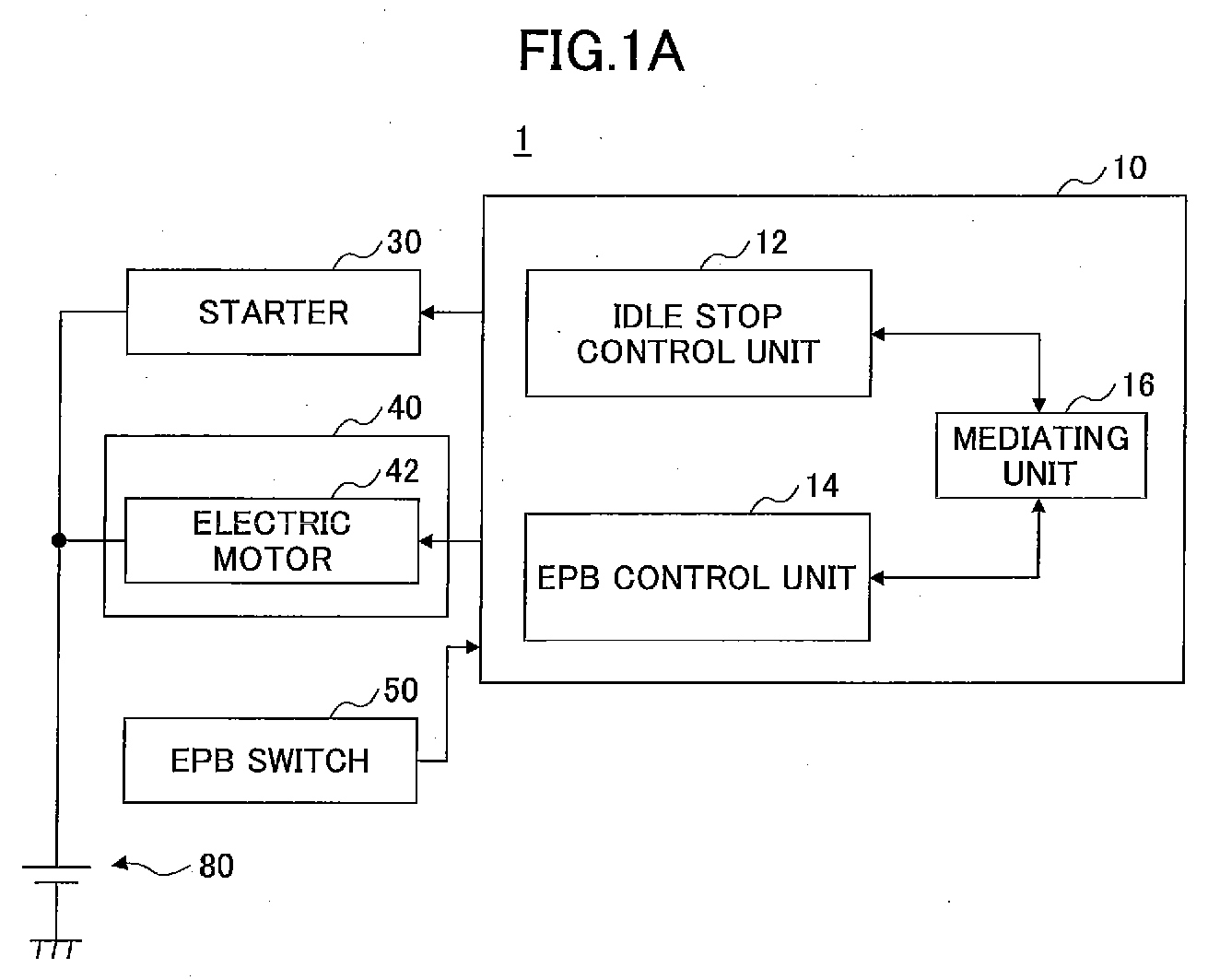
- FIGS. 1A and 1B illustrate a vehicle engine activation control system 1 according to an embodiment of the present invention.
- FIG. 1A is a configuration diagram of the vehicle engine activation control system 1.
- FIG. 1B schematically illustrates an example of an electric parking brake device 40.
- the vehicle engine activation control system 1 includes a control device 10, a starter 30, the electric parking brake device 40, and an EPB (Electric Parking Brake) switch 50.
- the control device 10 is formed by a computer such as an ECU (Electronic Control Unit).
- the control device 10 may be realized by a plurality of computers.
- the starter 30, an electric motor 42, and the EPB switch 50 are connected to the control device 10.
- the control device 10 includes an idle stop control unit 12, an EPB control unit 14, and a mediating unit 16.
- the idle stop control unit 12 executes idle stop control.
- the idle stop control is also referred to as S&S (Start & Stop).
- the idle stop control unit 12 causes an engine (not illustrated) to automatically stop, when a stop condition is established while the engine is operating. For example, when all of the following conditions (1) through (3) are satisfied, the stop condition is established.
- the idle stop control unit 12 drives the starter 30 and causes the engine to be automatically reactivated.
- engine automatic stop means the period from when the engine automatic stop is started to when the engine speed becomes zero.
- the EPB control unit 14 controls the electric motor 42.
- the EPB control unit 14 drives the electric motor 42 in response to a pressurizing request or a release request generated according to the operation state of the EPB switch 50.
- the pressurizing request is a signal requesting to apply a braking force on the wheel by the electric parking brake device 40
- the release request is a signal requesting to release the braking force applied on the wheel by the electric parking brake device 40.
- the starter 30 is connected to a battery 80.
- the starter 30 is driven by the power of the battery 80.
- the starter 30 is controlled by the idle stop control unit 12.
- the starter 30 is driven when the engine is activated (including the time of reactivation).
- the electric parking brake device 40 includes the electric motor 42, a gear mechanism 43, and a cable 44. Furthermore, the electric parking brake device 40 includes the EPB control unit 14.
- the electric motor 42 is provided on, for example, the rear wheel, together with the gear mechanism 43, the cable 44, etc. As illustrated in FIG. 1A , the electric motor 42 is connected to the battery 80. The electric motor 42 is driven by the power of the battery 80. The driving force of the electric motor 42 is transmitted to a brake shoe 63 used for parking, via the gear mechanism 43 and the cable 44. Accordingly, the brake shoe 63 is pressed against a brake drum 64, and a braking force is applied by the frictional force (parking braking force) between the brake shoe 63 and the brake drum 64.
- the electric motor 42 is controlled by the EPB control unit 14.
- the EPB control unit 14 drives the electric motor 42 in a direction of applying a braking force to the wheel, in response to a pressurizing request.
- the operation of driving the electric motor 42 in a direction of applying a braking force to the wheel is also referred to as "pressurize driving".
- the EPB control unit 14 pulls the cable 44 by normally rotating the electric motor 42, locks the wheel, and after locking the wheel, the EPB control unit 14 stops normally rotating the electric motor 42 and maintains the locked state by a maintaining device of the gear mechanism 43.
- the EPB control unit 14 drives the electric motor 42 in a direction of releasing the braking force applied to the wheel, in response to a release request.
- the operation of driving the electric motor 42 in a direction of releasing the braking force applied to the wheel is also referred to as "release driving".
- the EPB control unit 14 operates the gear mechanism 43 such that the tension of the cable 44 is loosened by reverse rotating the electric motor 42.
- the EPB switch 50 is provided in the vehicle interior.
- the EPB switch 50 generates a pressurizing request or a release request in response to input from the driver.
- the EPB switch 50 may have a form of, for example, a momentary switch. In this case, an electric signal that is generated when the EPB switch 50 is pressed when the electric parking brake device 40 is in a release state becomes a pressurizing request, and an electric signal that is generated when the EPB switch 50 is pressed when the electric parking brake device 40 is in a pressurize state becomes a release request.
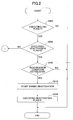
- FIG. 2 is a flowchart of a part (a part relevant to the reactivation of the engine) of a process executed by the idle stop control unit 12. The process of FIG. 2 is executed at predetermined cycles.
- step S200 the idle stop control unit 12 determines whether the executing S&S flag is "1".
- the executing S&S flag is set to "1" when the automatic stopping of the engine is started according to the establishment of the stop condition as described above.
- the process proceeds to step S202, and otherwise, the process of the present cycle is ended.
- step S202 the idle stop control unit 12 determines whether an executing reactivation flag is "0".
- the initial value of the executing reactivation flag is "0".
- the process proceeds to step S206, and otherwise, the process proceeds to step S302 of FIG. 3 .
- step S206 the idle stop control unit 12 determines whether the reactivation condition has been established.
- the reactivation condition is established when any one of the following conditions (4) through (6) is no longer satisfied, or when the condition (7) is satisfied.
- Condition (4) The speed of the own vehicle is less than or equal to a predetermined speed.
- step S212 the process of the present cycle is ended.
- step S212 the idle stop control unit 12 starts the reactivation of the engine. Specifically, the idle stop control unit 12 starts driving the starter 30.
- the idle stop control unit 12 may determine whether the reactivation of the engine is possible, before starting the reactivation of the engine. For example, in the case of a manual transmission vehicle, when the clutch pedal is not stepped on, it may be determined that the reactivation of the engine is not possible. When the reactivation of the engine is not possible, an alert warning, etc., may be output. Furthermore, when the determination result of step S206 is "YES", the idle stop control unit 12 may start driving the starter 30, after a predetermined time (for example, 100 ms).
- step S214 the idle stop control unit 12 sets the executing reactivation flag to "1".
- FIG. 3 is a flowchart of a part (a part relevant to the reactivation) of a process executed by the idle stop control unit 12. The process of FIG. 3 is executed when the determination result of step S202 of FIG. 2 is "NO".
- step S302 the idle stop control unit 12 determines whether the reactivation of the engine has not yet ended.
- the idle stop control unit 12 determines that the reactivation of the engine has not yet ended, when the engine speed is less than a predetermined idle speed.
- the idle stop control unit 12 may determine that the reactivation of the engine has not yet ended, when a predetermined time has not passed after the completion of the operation of the starter 30.
- the process proceeds to step S306, and otherwise (that is, when the reactivation of the engine is completed), the process proceeds to step S308.
- step S306 the idle stop control unit 12 continues the reactivation of the engine.
- the idle stop control unit 12 continues the driving of the starter 30.
- step S308 the idle stop control unit 12 sets the executing reactivation flag to "0".
- step S312 the idle stop control unit 12 sets the executing S&S flag to "0".
- FIG. 4 is a flowchart of a part (a part relevant to the release request) of a process executed by the EPB control unit 14. The process of FIG. 4 is executed at predetermined cycles.
- step S802 the EPB control unit 14 determines whether an EPB abnormality flag is "0".
- a state where the EPB abnormality flag is "1" indicates a state where an abnormality of the electric parking brake device 40 has been detected.
- the initial value of the EPB abnormality flag is "0".
- the process proceeds to step S804, and otherwise, the process of the present cycle is ended.
- step S804 the EPB control unit 14 determines whether an executing EPB release flag is "0". The initial value of the executing EPB release flag is "0". When the executing EPB release flag is "0", the process proceeds to step S806, and otherwise, the process proceeds to step S812.
- step S806 the EPB control unit 14 determines whether a release request is generated. When a release request is generated, the process proceeds to step S808, and otherwise, the process of the present cycle is ended.
- step S808 the EPB control unit 14 determines whether the EPB release prohibition flag is "0". The initial value of the EPB release prohibition flag is "0". The state of the EPB release prohibition flag is changed by the mediating unit 16 as described below with reference to FIG. 9. When the EPB release prohibition flag is "0", the process proceeds to step S810, and otherwise, the process of the present cycle is ended.
- step S810 the EPB control unit 14 sets the executing EPB release flag to "1".
- step S812 the EPB control unit 14 determines whether the release driving is not yet completed. When the release driving is not yet completed, the process proceeds to step S814, and otherwise, the process proceeds to step S820.
- step S814 the EPB control unit 14 starts or continues the release driving. Note that when starting the release driving, when the determination result of step S808 is "YES", the EPB control unit 14 may start the release driving after a predetermined time has passed (for example, one process cycle).
- step S816 the EPB control unit 14 determines whether the electric parking brake device 40 is normal.
- the EPB control unit 14 may determine whether the electric parking brake device 40 is normal based on an operation state, etc., of the electric motor 42.
- the process of the present cycle is ended, and otherwise, the process proceeds to step S818.
- step S818 the EPB control unit 14 sets the EPB abnormality flag to "1".
- step S818 the process proceeds to step S820.
- step S820 the EPB control unit 14 sets the executing EPB release flag to "0".
- FIG. 5 is a flowchart of a process executed by the mediating unit 16. The process of FIG. 5 is executed at predetermined cycles.
- step S900 the mediating unit 16 determines whether the executing S&S flag is "1".
- the executing S&S flag is set to "1" when the automatic stopping of the engine is started according to the establishment of the stop condition as described above.
- the process proceeds to step S902, and otherwise, the process proceeds to step S906.
- step S902 the mediating unit 16 determines whether the EPB release prohibition flag is "0". When the EPB release prohibition flag is "0", the process proceeds to step S904, and otherwise, the process of the present cycle is ended.
- step S904 the mediating unit 16 sets the EPB release prohibition flag to "1".
- step S906 the mediating unit 16 determines whether the EPB release prohibition flag is "1". When the EPB release prohibition flag is "1", the process proceeds to step S908, and otherwise, the process of the present cycle is ended.
- step S908 the mediating unit 16 is able to set and maintain the EPB release prohibition flag to "1", during a period from when the automatic stop of the engine is started by the idle stop control unit 12 to when the reactivation is completed (step S904).
- the EPB release prohibition flag is "1" as described above, the release driving by the EPB control unit 14 is prohibited ("NO" in step S808).
- the engine is reactivated in response to a release request, it is possible to prohibit the release driving of the electric motor 42 by the EPB control unit 14 in response to the release request.
- the engine is reactivating, it is possible to prohibit the release driving of the electric motor 42 by the EPB control unit 14.
- the mediating unit 16 changes the EPB release prohibition flag from “1” to “0”; however, the mediating unit 16 may change the EPB release prohibition flag from "1” to "0” when the driving of the starter 30 is completed.
- the driving state of the starter 30 may be determined based on information (flag) from the idle stop control unit 12.
- FIG. 6 is a timing chart of an example of changes in time series of the respective states when reactivating an engine.
- the changes in time series illustrated in FIG. 6 are realized by the processes illustrated in FIGS. 4 and 5 .
- the state of the engine ENG state
- the state of the executing reactivation flag activation request
- the state of the electric motor 42 EPB state
- the state of the EPB switch 50 EPB SW
- the state of the EPB release prohibition flag are illustrated in the stated order from the top.
- an idle state is expressed by "idle”
- a fuel cut state is expressed by "F/C”
- a state before reactivation after completing the engine automatic stop is expressed by "executing S&S”
- an engine reactivation state is expressed by "reactivating ENG”.
- the state of the electric motor 42 is expressed by "release driving state” which is the driving state (release driving state) according to the release request, and "release state” which is the state where the release driving according to the release request has ended.
- the “release state” is realized initially or after the release driving is completed, and corresponds to a state where a braking force is not applied by the electric parking brake device.
- the “pressurize state” corresponds to a state where a braking force is applied by the electric parking brake device.
- a release request is generated as the driver operates the EPB switch 50, and accordingly, a reactivation condition is established ("YES” in step S206), and the reactivation of the engine is started (step S212).
- the EPB release prohibition flag which has been set to "1" according to the engine automatic stop, remains as "1". Therefore, the release driving according to the release request generated at the time t0 is prohibited ("NO” in step S808). This prohibition state is continued until the time t1 at which the reactivation of the engine is completed and the EPB release prohibition flag becomes "0" (step S908).
- a release request is generated as the driver operates the EPB switch 50 again.
- the engine is in an operating state, and therefore the EPB release prohibition flag is not "1". Therefore, the electric motor 42 is caused to perform release driving in response to the release request generated at the time t2 (step S814).
- the release driving state of the electric motor 42 is completed at the time t3 ("NO" in step S812).
- FIG. 7 is a timing chart of another example of changes in time series of the respective states when reactivating an engine.
- the changes in time series illustrated in FIG. 7 are realized by the processes illustrated in FIGS. 4 and 5 .
- the expressions are the same as those of FIG. 6 .
- a reactivation condition is established without being caused by a release request ("YES” in step S206), and the reactivation of the engine is started (step S212).
- a release request is generated as the driver operates the EPB switch 50.
- the EPB release prohibition flag which has been set to "1" according to the engine automatic stop, remains as "1". Therefore, the release driving according to the release request generated at the time t1 is prohibited ("NO” in step S808). This prohibition state is continued until the time t2 at which the reactivation of the engine is completed and the EPB release prohibition flag becomes "0" (step S908).
- a release request is generated as the driver operates the EPB switch 50 again.
- the engine is in an operating state, and therefore the EPB release prohibition flag is not "1". Therefore, the electric motor 42 is caused to perform release driving in response to the release request generated at the time t3 (step S814).
- the release driving state of the electric motor 42 is completed at the time t4 ("NO" in step S812).
- the reactivation condition is established when a release request is generated, and when the reactivation condition is established, the EPB release prohibition flag is set to "1". Accordingly, the reactivation condition will not be established during the release driving of the electric motor 42. Furthermore, when the engine is being reactivated by the idle stop control unit 12, the EPB release prohibition flag is maintained at "1". Therefore, it is possible to prevent a situation where both the release driving of the electric motor 42 and the driving state of the starter 30 for the reactivation of the engine by the idle stop control unit 12, are realized at the same time.
- the load on the battery 80 can be reduced, compared to a configuration in which the release driving state of the electric motor 42 and the driving state of the starter 30 may be realized at the same time when reactivating the engine.
- the electric parking brake device 40 operates in response to input from the driver via the EPB switch 50. That is, the EPB control unit 14 causes the electric motor 42 to perform pressurize driving in response to a pressurizing request, and also causes the electric motor 42 to perform release driving in response to a release request (however, with respect to the release request, there are cases where release driving is prohibited as described above). Therefore, according to the present embodiment, the electric parking brake device 40 can be configured to operate in response to input from the driver, and therefore it is possible to realize a drive mode in which the driver's intention is reflected.
- the reactivation of the engine is prioritized over the release driving, and therefore it is possible to avoid inconveniences (for example, the vehicle slips down) that may arise when reactivation of the engine is executed after release driving. That is, according to the present embodiment, it is possible to avoid a situation where the release state of the electric parking brake device is realized during the reactivation of the engine, and therefore it is possible to avoid a situation where the vehicle slips down while the engine is being reactivated.
- the mediating unit 16 determines whether the engine is being reactivated by the idle stop control unit 12. The determination as to whether the engine is being reactivated may be made based on whether the executing reactivation flag is "1". Alternatively, the mediating unit 16 may determine whether the reactivation condition establish flag is "1", instead of whether the executing reactivation flag is "1".
- the mediating unit 16 may determine that the engine is being reactivated, from when the executing reactivation flag (or the reactivation condition establish flag) becomes "1" to when the driving of the starter 30 is completed.
- the process proceeds to step S902, and otherwise, the process proceeds to step S906.
- the reactivation condition may be established during the release driving according to a release request. When the reactivation condition is established during the release driving according to a release request, both driving states are allowed, or the release driving is discontinued, and reactivation of the engine is executed.
- the vehicle engine activation control system 1 may have a configuration in which the prohibition is not executed.
- the load on the battery 80 can be reduced with respect to the engine reactivation in response to the release request.
- the operation of the electric parking brake device is realized according to input form the EPB switch 50; however, as another mode, it may be possible to select an automatic mode.
- the operation of the electric parking brake device (pressurize driving and release driving of the electric motor 42) is automatically realized according to, for example, the control state of the idle stop control unit 12.
- the EPB switch 50 may be able to generate a release request, not only in the pressurize state but also in the pressurize driving state. Similarly, the EPB switch 50 may be able to generate a pressurizing request, not only in the release state but also in the release driving state.
- the function of the mediating unit 16 may be realized by the EPB control unit 14.
- the EPB control unit 14 may determine whether the executing S&S flag is "0", instead of the process of step S808.
- the mediating unit 16 prioritizes the reactivation of the engine only with respect to a release request; however, the mediating unit 16 may also prioritize the reactivation of the engine with respect to a pressurizing request, by the same mode as the release request.
- the processes of FIGS. 4 and 5 in which "release” is replaced with “pressurize”, may be executed instead of the processes of FIGS. 4 and 5 .
- the condition (7) relevant to the reactivation condition may be replaced with the following condition (7-1).
- Condition (7-1) Either a release request or a pressurizing request is generated by operating the EPB switch 50.
- the mediating unit 16 prioritizes the reactivation of the engine only with respect to a release request; however, the mediating unit 16 may prioritize the reactivation of the engine only with respect to a pressurizing request.
- the processes of FIGS. 4 and 5 in which "release” is replaced with “pressurize”, may be executed instead of the processes of FIGS. 4 and 5 .
- the condition (7) relevant to the reactivation condition may be replaced with the following condition (7-2).
- the present example is not so limited. For example, as long as the EPB abnormality flag is "0", once a release request is generated, even when the release driving relevant to the release request is prohibited because the EPB release prohibition flag is "1", a release wait state of waiting for the prohibition state may be realized (a state of waiting for the EPB release prohibition flag to become "0").
- the release driving is prohibited (waited on), and the engine is reactivated; however, the release driving is realized after the engine is reactivated (without the need of operating the EPB switch 50 again).
- a vehicle engine activation control system capable of reducing the load on the battery when reactivating the engine according to idle stop control, while configuring the electric parking brake device to operate according to input from the driver.
Landscapes
- Engineering & Computer Science (AREA)
- Mechanical Engineering (AREA)
- General Engineering & Computer Science (AREA)
- Transportation (AREA)
- Chemical & Material Sciences (AREA)
- Combustion & Propulsion (AREA)
- Control Of Vehicle Engines Or Engines For Specific Uses (AREA)
- Regulating Braking Force (AREA)
- Automation & Control Theory (AREA)
- Output Control And Ontrol Of Special Type Engine (AREA)
- Braking Systems And Boosters (AREA)
- Control Of Driving Devices And Active Controlling Of Vehicle (AREA)
Abstract
Description
- The present invention is related to a vehicle engine activation control system.
- An electric parking brake system that causes a parking brake to automatically operate by an electric motor, and a parking brake control device applied to a vehicle provided with an idle stop system that automatically stops the engine, are known (see, for example, Patent Document 1). This parking brake control device includes a parking brake control unit that causes a parking brake to automatically operate in a direction of applying a braking force according to the implementation of idle stopping, and a parking brake release unit that causes the parking brake to automatically operate in a direction of releasing the braking force when there is a request to release the idle stopping and automatically reactivate the engine. The parking brake release unit allows the automatic release, on condition that the start driving force of the vehicle is greater than or equal to a predetermined value.
- [Patent Document 1] Japanese Laid-open Patent Publication No.
2012-035773 - However, in the configuration described in
Patent Document 1, the electric parking brake automatically operates in conjunction with the control state of idle stopping, and therefore the operation of the electric parking brake is implemented with no relation to the driver's intention, which is a problem in that the driver's intention cannot be reflected. - Meanwhile, if the electric parking brake control device is configured to operate according to input from the driver in order to reflect the driver's intention, the reactivation of the engine and the operation of the electric parking brake device are performed at the same time, and the load on the battery may become high. This is because the starter is driven when the engine is reactivated, and the electric motor is driven when the electric parking brake device operates, and the power of the battery is used for driving both of these elements.
- According to one aspect of the present invention, a vehicle engine activation control system includes a starter connected to a battery; an input unit configured to generate an operation request in response to input from a driver; an electric parking brake device including an electric motor connected to the battery, wherein the electric motor starts driving in response to the operation request; an idle stop control unit configured to automatically stop an engine and automatically reactivate the engine by the starter; and a mediating unit configured to prohibit the driving of the electric motor in response to a predetermined operation request, in at least one of a case where the predetermined operation request is generated while the engine is automatically stopping or after the automatic stopping of the engine is completed, and a case where the predetermined operation request is generated during the reactivation of the engine.
- Other objects, features and advantages of the present invention will become more apparent from the following detailed description when read in conjunction with the accompanying drawings, in which:
-
FIGS. 1A and 1B illustrate a vehicle engine activation control system according to an embodiment of the present invention; -
FIG. 2 is a flowchart of a part of a process executed by an idle stop control unit (part 1) ; -
FIG. 3 is a flowchart of a part of a process executed by the idle stop control unit (part 2) ; -
FIG. 4 is a flowchart of a part of a process executed by an EPB control unit; -
FIG. 5 is a flowchart of a process executed by a mediating unit; -
FIG. 6 is a timing chart of an example of changes in time series of the respective states when reactivating an engine; and -
FIG. 7 is a timing chart of another example of changes in time series of the respective states when reactivating an engine. - In the following, with reference to drawings, a description is given of the best mode for carrying out the present invention.
-
FIGS. 1A and 1B illustrate a vehicle engineactivation control system 1 according to an embodiment of the present invention.FIG. 1A is a configuration diagram of the vehicle engineactivation control system 1.FIG. 1B schematically illustrates an example of an electricparking brake device 40. - As illustrated in
FIG. 1A , the vehicle engineactivation control system 1 includes acontrol device 10, astarter 30, the electricparking brake device 40, and an EPB (Electric Parking Brake)switch 50. - The
control device 10 is formed by a computer such as an ECU (Electronic Control Unit). Thecontrol device 10 may be realized by a plurality of computers. To thecontrol device 10, thestarter 30, anelectric motor 42, and theEPB switch 50 are connected. - The
control device 10 includes an idlestop control unit 12, anEPB control unit 14, and amediating unit 16. - The idle
stop control unit 12 executes idle stop control. The idle stop control is also referred to as S&S (Start & Stop). The idlestop control unit 12 causes an engine (not illustrated) to automatically stop, when a stop condition is established while the engine is operating. For example, when all of the following conditions (1) through (3) are satisfied, the stop condition is established. - Condition (1): The speed of the own vehicle is less than or equal to a predetermined speed.
- Condition (2): The accelerator pedal is not stepped on.
- Condition (3): The negative pressure inside the brake booster is closer to vacuum than a predetermined threshold.
- When a reactivation condition is established during the engine automatic stop or after the engine automatic stop has been completed, the idle
stop control unit 12 drives thestarter 30 and causes the engine to be automatically reactivated. During engine automatic stop means the period from when the engine automatic stop is started to when the engine speed becomes zero. - The
EPB control unit 14 controls theelectric motor 42. TheEPB control unit 14 drives theelectric motor 42 in response to a pressurizing request or a release request generated according to the operation state of theEPB switch 50. The pressurizing request is a signal requesting to apply a braking force on the wheel by the electricparking brake device 40, and the release request is a signal requesting to release the braking force applied on the wheel by the electricparking brake device 40. - An operation example of the
mediating unit 16 is described below. - The
starter 30 is connected to abattery 80. Thestarter 30 is driven by the power of thebattery 80. Thestarter 30 is controlled by the idlestop control unit 12. Thestarter 30 is driven when the engine is activated (including the time of reactivation). - As illustrated in
FIG. 1B , the electricparking brake device 40 includes theelectric motor 42, agear mechanism 43, and acable 44. Furthermore, the electricparking brake device 40 includes theEPB control unit 14. - The
electric motor 42 is provided on, for example, the rear wheel, together with thegear mechanism 43, thecable 44, etc. As illustrated inFIG. 1A , theelectric motor 42 is connected to thebattery 80. Theelectric motor 42 is driven by the power of thebattery 80. The driving force of theelectric motor 42 is transmitted to abrake shoe 63 used for parking, via thegear mechanism 43 and thecable 44. Accordingly, thebrake shoe 63 is pressed against abrake drum 64, and a braking force is applied by the frictional force (parking braking force) between thebrake shoe 63 and thebrake drum 64. - The
electric motor 42 is controlled by theEPB control unit 14. TheEPB control unit 14 drives theelectric motor 42 in a direction of applying a braking force to the wheel, in response to a pressurizing request. In the following, the operation of driving theelectric motor 42 in a direction of applying a braking force to the wheel is also referred to as "pressurize driving". For example, theEPB control unit 14 pulls thecable 44 by normally rotating theelectric motor 42, locks the wheel, and after locking the wheel, theEPB control unit 14 stops normally rotating theelectric motor 42 and maintains the locked state by a maintaining device of thegear mechanism 43. TheEPB control unit 14 drives theelectric motor 42 in a direction of releasing the braking force applied to the wheel, in response to a release request. In the following, the operation of driving theelectric motor 42 in a direction of releasing the braking force applied to the wheel is also referred to as "release driving". For example, theEPB control unit 14 operates thegear mechanism 43 such that the tension of thecable 44 is loosened by reverse rotating theelectric motor 42. - The
EPB switch 50 is provided in the vehicle interior. TheEPB switch 50 generates a pressurizing request or a release request in response to input from the driver. TheEPB switch 50 may have a form of, for example, a momentary switch. In this case, an electric signal that is generated when theEPB switch 50 is pressed when the electricparking brake device 40 is in a release state becomes a pressurizing request, and an electric signal that is generated when theEPB switch 50 is pressed when the electricparking brake device 40 is in a pressurize state becomes a release request. - Next, with reference to
FIGS. 2 through 7 , a description is given of an operation example of the vehicle engineactivation control system 1. -
FIG. 2 is a flowchart of a part (a part relevant to the reactivation of the engine) of a process executed by the idlestop control unit 12. The process ofFIG. 2 is executed at predetermined cycles. - In step S200, the idle
stop control unit 12 determines whether the executing S&S flag is "1". The executing S&S flag is set to "1" when the automatic stopping of the engine is started according to the establishment of the stop condition as described above. When the executing S&S flag is "1", the process proceeds to step S202, and otherwise, the process of the present cycle is ended. - In step S202, the idle
stop control unit 12 determines whether an executing reactivation flag is "0". The initial value of the executing reactivation flag is "0". When the executing reactivation flag is "0", the process proceeds to step S206, and otherwise, the process proceeds to step S302 ofFIG. 3 . - In step S206, the idle
stop control unit 12 determines whether the reactivation condition has been established. For example, the reactivation condition is established when any one of the following conditions (4) through (6) is no longer satisfied, or when the condition (7) is satisfied. Condition (4): The speed of the own vehicle is less than or equal to a predetermined speed. - Condition (5): The accelerator pedal is not stepped on.
- Condition (6): The negative pressure inside the brake booster is closer to vacuum than a predetermined threshold.
- Condition (7): A release request is generated according to an operation to the
EPB switch 50. Note that in the case of a manual transmission vehicle, the reactivation condition may be satisfied in cases other than when the shift range is N (neutral). - When the reactivation condition is established, the process proceeds to step S212, and otherwise, the process of the present cycle is ended.
- In step S212, the idle
stop control unit 12 starts the reactivation of the engine. Specifically, the idlestop control unit 12 starts driving thestarter 30. Note that the idlestop control unit 12 may determine whether the reactivation of the engine is possible, before starting the reactivation of the engine. For example, in the case of a manual transmission vehicle, when the clutch pedal is not stepped on, it may be determined that the reactivation of the engine is not possible. When the reactivation of the engine is not possible, an alert warning, etc., may be output. Furthermore, when the determination result of step S206 is "YES", the idlestop control unit 12 may start driving thestarter 30, after a predetermined time (for example, 100 ms). - In step S214, the idle
stop control unit 12 sets the executing reactivation flag to "1". -
FIG. 3 is a flowchart of a part (a part relevant to the reactivation) of a process executed by the idlestop control unit 12. The process ofFIG. 3 is executed when the determination result of step S202 ofFIG. 2 is "NO". - In step S302, the idle
stop control unit 12 determines whether the reactivation of the engine has not yet ended. The idlestop control unit 12 determines that the reactivation of the engine has not yet ended, when the engine speed is less than a predetermined idle speed. Alternatively, the idlestop control unit 12 may determine that the reactivation of the engine has not yet ended, when a predetermined time has not passed after the completion of the operation of thestarter 30. When the reactivation of the engine has not yet ended, the process proceeds to step S306, and otherwise (that is, when the reactivation of the engine is completed), the process proceeds to step S308. - In step S306, the idle
stop control unit 12 continues the reactivation of the engine. For example, the idlestop control unit 12 continues the driving of thestarter 30. - In step S308, the idle
stop control unit 12 sets the executing reactivation flag to "0". - In step S312, the idle
stop control unit 12 sets the executing S&S flag to "0". -
FIG. 4 is a flowchart of a part (a part relevant to the release request) of a process executed by theEPB control unit 14. The process ofFIG. 4 is executed at predetermined cycles. - In step S802, the
EPB control unit 14 determines whether an EPB abnormality flag is "0". A state where the EPB abnormality flag is "1" indicates a state where an abnormality of the electricparking brake device 40 has been detected. The initial value of the EPB abnormality flag is "0". When the EPB abnormality flag is "0", the process proceeds to step S804, and otherwise, the process of the present cycle is ended. - In step S804, the
EPB control unit 14 determines whether an executing EPB release flag is "0". The initial value of the executing EPB release flag is "0". When the executing EPB release flag is "0", the process proceeds to step S806, and otherwise, the process proceeds to step S812. - In step S806, the
EPB control unit 14 determines whether a release request is generated. When a release request is generated, the process proceeds to step S808, and otherwise, the process of the present cycle is ended. - In step S808, the
EPB control unit 14 determines whether the EPB release prohibition flag is "0". The initial value of the EPB release prohibition flag is "0". The state of the EPB release prohibition flag is changed by the mediatingunit 16 as described below with reference to FIG. 9. When the EPB release prohibition flag is "0", the process proceeds to step S810, and otherwise, the process of the present cycle is ended. - In step S810, the
EPB control unit 14 sets the executing EPB release flag to "1". - In step S812, the
EPB control unit 14 determines whether the release driving is not yet completed. When the release driving is not yet completed, the process proceeds to step S814, and otherwise, the process proceeds to step S820. - In step S814, the
EPB control unit 14 starts or continues the release driving. Note that when starting the release driving, when the determination result of step S808 is "YES", theEPB control unit 14 may start the release driving after a predetermined time has passed (for example, one process cycle). - In step S816, the
EPB control unit 14 determines whether the electricparking brake device 40 is normal. TheEPB control unit 14 may determine whether the electricparking brake device 40 is normal based on an operation state, etc., of theelectric motor 42. When the electricparking brake device 40 is normal, the process of the present cycle is ended, and otherwise, the process proceeds to step S818. - In step S818, the
EPB control unit 14 sets the EPB abnormality flag to "1". When the process of step S818 is ended, the process proceeds to step S820. - In step S820, the
EPB control unit 14 sets the executing EPB release flag to "0". - According to the process of
FIG. 4 , even when a release request is generated, if the EPB release prohibition flag is "1", theEPB control unit 14 prohibits the release driving ("NO" in step S808). -
FIG. 5 is a flowchart of a process executed by the mediatingunit 16. The process ofFIG. 5 is executed at predetermined cycles. - In step S900, the mediating
unit 16 determines whether the executing S&S flag is "1". The executing S&S flag is set to "1" when the automatic stopping of the engine is started according to the establishment of the stop condition as described above. When the executing S&S flag is "1", the process proceeds to step S902, and otherwise, the process proceeds to step S906. - In step S902, the mediating
unit 16 determines whether the EPB release prohibition flag is "0". When the EPB release prohibition flag is "0", the process proceeds to step S904, and otherwise, the process of the present cycle is ended. - In step S904, the mediating
unit 16 sets the EPB release prohibition flag to "1". - In step S906, the mediating
unit 16 determines whether the EPB release prohibition flag is "1". When the EPB release prohibition flag is "1", the process proceeds to step S908, and otherwise, the process of the present cycle is ended. - In step S908, the mediating
unit 16 is able to set and maintain the EPB release prohibition flag to "1", during a period from when the automatic stop of the engine is started by the idlestop control unit 12 to when the reactivation is completed (step S904). When the EPB release prohibition flag is "1", as described above, the release driving by theEPB control unit 14 is prohibited ("NO" in step S808). As described above, according to the process ofFIG. 5 , when the engine is reactivated in response to a release request, it is possible to prohibit the release driving of theelectric motor 42 by theEPB control unit 14 in response to the release request. Furthermore, according to the process ofFIG. 5 , when the engine is reactivating, it is possible to prohibit the release driving of theelectric motor 42 by theEPB control unit 14. - Note that in the process of
FIG. 5 , when the executing S&S flag is changed from "1" to "0" as the reactivation of the engine is completed, the mediatingunit 16 changes the EPB release prohibition flag from "1" to "0"; however, the mediatingunit 16 may change the EPB release prohibition flag from "1" to "0" when the driving of thestarter 30 is completed. The driving state of thestarter 30 may be determined based on information (flag) from the idlestop control unit 12. -
FIG. 6 is a timing chart of an example of changes in time series of the respective states when reactivating an engine. The changes in time series illustrated inFIG. 6 are realized by the processes illustrated inFIGS. 4 and5 . InFIG. 6 , the state of the engine (ENG state), the state of the executing reactivation flag (activation request), the state of the electric motor 42 (EPB state), the state of the EPB switch 50 (EPB SW), and the state of the EPB release prohibition flag, are illustrated in the stated order from the top. As the state of the engine, an idle state is expressed by "idle", a fuel cut state is expressed by "F/C", a state before reactivation after completing the engine automatic stop is expressed by "executing S&S", and an engine reactivation state is expressed by "reactivating ENG". Furthermore, the state of theelectric motor 42 is expressed by "release driving state" which is the driving state (release driving state) according to the release request, and "release state" which is the state where the release driving according to the release request has ended. The "release state" is realized initially or after the release driving is completed, and corresponds to a state where a braking force is not applied by the electric parking brake device. The "pressurize state" corresponds to a state where a braking force is applied by the electric parking brake device. - In the example of
FIG. 6 , after the completion of the engine automatic stop, at the time t0, a release request is generated as the driver operates theEPB switch 50, and accordingly, a reactivation condition is established ("YES" in step S206), and the reactivation of the engine is started (step S212). At this time, the EPB release prohibition flag which has been set to "1" according to the engine automatic stop, remains as "1". Therefore, the release driving according to the release request generated at the time t0 is prohibited ("NO" in step S808). This prohibition state is continued until the time t1 at which the reactivation of the engine is completed and the EPB release prohibition flag becomes "0" (step S908). At the time t2 after the time t1, a release request is generated as the driver operates theEPB switch 50 again. At the time t2, the engine is in an operating state, and therefore the EPB release prohibition flag is not "1". Therefore, theelectric motor 42 is caused to perform release driving in response to the release request generated at the time t2 (step S814). In the example ofFIG. 6 , the release driving state of theelectric motor 42 is completed at the time t3 ("NO" in step S812). -
FIG. 7 is a timing chart of another example of changes in time series of the respective states when reactivating an engine. The changes in time series illustrated inFIG. 7 are realized by the processes illustrated inFIGS. 4 and5 . The expressions are the same as those ofFIG. 6 . - In the example of
FIG. 7 , after the completion of the engine automatic stop, at the time t0, a reactivation condition is established without being caused by a release request ("YES" in step S206), and the reactivation of the engine is started (step S212). At the time t1, a release request is generated as the driver operates theEPB switch 50. At this time, the EPB release prohibition flag which has been set to "1" according to the engine automatic stop, remains as "1". Therefore, the release driving according to the release request generated at the time t1 is prohibited ("NO" in step S808). This prohibition state is continued until the time t2 at which the reactivation of the engine is completed and the EPB release prohibition flag becomes "0" (step S908). At the time t3 after the time t2, a release request is generated as the driver operates theEPB switch 50 again. At the time t3, the engine is in an operating state, and therefore the EPB release prohibition flag is not "1". Therefore, theelectric motor 42 is caused to perform release driving in response to the release request generated at the time t3 (step S814). In the example ofFIG. 7 , the release driving state of theelectric motor 42 is completed at the time t4 ("NO" in step S812). - According to the present embodiment, the reactivation condition is established when a release request is generated, and when the reactivation condition is established, the EPB release prohibition flag is set to "1". Accordingly, the reactivation condition will not be established during the release driving of the
electric motor 42. Furthermore, when the engine is being reactivated by the idlestop control unit 12, the EPB release prohibition flag is maintained at "1". Therefore, it is possible to prevent a situation where both the release driving of theelectric motor 42 and the driving state of thestarter 30 for the reactivation of the engine by the idlestop control unit 12, are realized at the same time. Accordingly, the load on thebattery 80 can be reduced, compared to a configuration in which the release driving state of theelectric motor 42 and the driving state of thestarter 30 may be realized at the same time when reactivating the engine. As a result, it is possible to reduce the inconvenience that arises when the release driving state of theelectric motor 42 and the driving state of thestarter 30 are realized at the same time; typically, the inconvenience in which the release driving of theelectric motor 42 and/or the driving of thestarter 30 cannot be implemented in a desired mode due to a drop in the voltage of thebattery 80. - Furthermore, in the present embodiment, the electric
parking brake device 40 operates in response to input from the driver via theEPB switch 50. That is, theEPB control unit 14 causes theelectric motor 42 to perform pressurize driving in response to a pressurizing request, and also causes theelectric motor 42 to perform release driving in response to a release request (however, with respect to the release request, there are cases where release driving is prohibited as described above). Therefore, according to the present embodiment, the electricparking brake device 40 can be configured to operate in response to input from the driver, and therefore it is possible to realize a drive mode in which the driver's intention is reflected. - According to the present embodiment, the reactivation of the engine is prioritized over the release driving, and therefore it is possible to avoid inconveniences (for example, the vehicle slips down) that may arise when reactivation of the engine is executed after release driving. That is, according to the present embodiment, it is possible to avoid a situation where the release state of the electric parking brake device is realized during the reactivation of the engine, and therefore it is possible to avoid a situation where the vehicle slips down while the engine is being reactivated.
- Preferred embodiments of the present invention are described above; however, the present invention is not limited to the specific embodiments described herein, and variations and modifications may be made without departing from the spirit and scope of the present invention.
- For example, in the embodiment described above, the reactivation condition is satisfied when a release request is generated by an operation to the
EPB switch 50; however, the reactivation condition may not be satisfied when a release request is generated. In this case, in the process ofFIG. 5 , in step S900, the mediatingunit 16 determines whether the engine is being reactivated by the idlestop control unit 12. The determination as to whether the engine is being reactivated may be made based on whether the executing reactivation flag is "1". Alternatively, the mediatingunit 16 may determine whether the reactivation condition establish flag is "1", instead of whether the executing reactivation flag is "1". Alternatively, the mediatingunit 16 may determine that the engine is being reactivated, from when the executing reactivation flag (or the reactivation condition establish flag) becomes "1" to when the driving of thestarter 30 is completed. When the engine is being reactivated, the process proceeds to step S902, and otherwise, the process proceeds to step S906. In this modified example, the reactivation condition may be established during the release driving according to a release request. When the reactivation condition is established during the release driving according to a release request, both driving states are allowed, or the release driving is discontinued, and reactivation of the engine is executed. - Furthermore, in the embodiment described above, when a release request is generated during reactivation after the reactivation starting point, the release driving of the
electric motor 42 according to the release request is prohibited (seeFIG. 7 ); however, the vehicle engineactivation control system 1 may have a configuration in which the prohibition is not executed. In such a configuration also, when a release request is generated during engine automatic stop or after completion of engine automatic stop, by prohibiting the release driving of theelectric motor 42 according to the release request (seeFIG. 6 ), the load on thebattery 80 can be reduced with respect to the engine reactivation in response to the release request. - Furthermore, in the embodiment described above, the operation of the electric parking brake device is realized according to input form the
EPB switch 50; however, as another mode, it may be possible to select an automatic mode. In this case, in the automatic mode, the operation of the electric parking brake device (pressurize driving and release driving of the electric motor 42) is automatically realized according to, for example, the control state of the idlestop control unit 12. - Furthermore, in the embodiment described above, the
EPB switch 50 may be able to generate a release request, not only in the pressurize state but also in the pressurize driving state. Similarly, theEPB switch 50 may be able to generate a pressurizing request, not only in the release state but also in the release driving state. - Furthermore, in the embodiment described above, the function of the mediating
unit 16 may be realized by theEPB control unit 14. For example, in the embodiment described above, when theEPB control unit 14 executes the process of the mediatingunit 16 ofFIG. 5 , theEPB control unit 14 may determine whether the executing S&S flag is "0", instead of the process of step S808. - Furthermore, in the embodiment described above, the mediating
unit 16 prioritizes the reactivation of the engine only with respect to a release request; however, the mediatingunit 16 may also prioritize the reactivation of the engine with respect to a pressurizing request, by the same mode as the release request. Specifically, the processes ofFIGS. 4 and5 , in which "release" is replaced with "pressurize", may be executed instead of the processes ofFIGS. 4 and5 . In this case, the condition (7) relevant to the reactivation condition may be replaced with the following condition (7-1). Condition (7-1) Either a release request or a pressurizing request is generated by operating theEPB switch 50. - Furthermore, in the embodiment described above, the mediating
unit 16 prioritizes the reactivation of the engine only with respect to a release request; however, the mediatingunit 16 may prioritize the reactivation of the engine only with respect to a pressurizing request. For example, the processes ofFIGS. 4 and5 , in which "release" is replaced with "pressurize", may be executed instead of the processes ofFIGS. 4 and5 . In this case, the condition (7) relevant to the reactivation condition may be replaced with the following condition (7-2). - Condition (7-2) A pressurizing request is generated by operating the
EPB switch 50. - Furthermore, in the example of
FIG. 4 , even when a release request is generated once, if the release driving relevant to the release request is prohibited because the EPB release prohibition flag is "1", it is necessary to generate a new release request in order to realize release driving. However, the present example is not so limited. For example, as long as the EPB abnormality flag is "0", once a release request is generated, even when the release driving relevant to the release request is prohibited because the EPB release prohibition flag is "1", a release wait state of waiting for the prohibition state may be realized (a state of waiting for the EPB release prohibition flag to become "0"). In this case, for example, assuming that a driver operates theEPB switch 50 to generate a release request after the engine automatic stop is completed, the release driving is prohibited (waited on), and the engine is reactivated; however, the release driving is realized after the engine is reactivated (without the need of operating theEPB switch 50 again). - According to the embodiments, it is possible to provide a vehicle engine activation control system capable of reducing the load on the battery when reactivating the engine according to idle stop control, while configuring the electric parking brake device to operate according to input from the driver.
- The present application is based on and claims the benefit of priority of Japanese Priority Application No.
2015-089755, filed on April 24, 2015
Claims (4)
- A vehicle engine activation control system (1) comprising:a starter (30) connected to a battery (80) ;an input unit (50) configured to generate an operation request in response to input from a driver;an electric parking brake device (40) including an electric motor (42) connected to the battery, wherein the electric motor starts driving in response to the operation request;an idle stop control unit (12) configured to automatically stop an engine and automatically reactivate the engine by the starter; anda mediating unit (16) configured to prohibit the driving of the electric motor in response to a predetermined operation request, in at least one of a case where the predetermined operation request is generated while the engine is automatically stopping or after the automatic stopping of the engine is completed, and a case where the predetermined operation request is generated during the reactivation of the engine.
- The vehicle engine activation control system according to claim 1, wherein
the operation request includesa pressurizing request generated in a release state of the electric parking brake device, wherein the pressurizing request is for requesting a pressurize state of the electric parking brake device in which a braking force is applied on a wheel, anda release request generated in the pressurize state of the electric parking brake device, wherein the release request is for requesting the release state of the electric parking brake device in which the braking force applied on the wheel is released, and whereinthe predetermined operation request includes at least one of the pressurizing request and the release request. - The vehicle engine activation control system according to claim 2, wherein
the predetermined operation request includes the release request,
the mediating unit prohibits the driving of the electric motor in response to the release request, when the release request is generated while the engine is automatically stopping or after the automatic stopping of the engine is completed, and
the idle stop control unit automatically reactivates the engine, when the release request is generated while the engine is automatically stopping or after the automatic stopping of the engine is completed. - The vehicle engine activation control system according to claim 3, wherein
the mediating unit further prohibits the driving of the electric motor in response to the release request, when the release request is generated during the reactivation of the engine.
Applications Claiming Priority (1)
| Application Number | Priority Date | Filing Date | Title |
|---|---|---|---|
| JP2015089755A JP2016203871A (en) | 2015-04-24 | 2015-04-24 | Vehicle engine start control system |
Publications (2)
| Publication Number | Publication Date |
|---|---|
| EP3085594A2 true EP3085594A2 (en) | 2016-10-26 |
| EP3085594A3 EP3085594A3 (en) | 2016-11-30 |
Family
ID=55854611
Family Applications (1)
| Application Number | Title | Priority Date | Filing Date |
|---|---|---|---|
| EP16166694.6A Withdrawn EP3085594A3 (en) | 2015-04-24 | 2016-04-22 | Vehicle engine activation control system |
Country Status (4)
| Country | Link |
|---|---|
| US (1) | US9630612B2 (en) |
| EP (1) | EP3085594A3 (en) |
| JP (1) | JP2016203871A (en) |
| CN (1) | CN106065818A (en) |
Families Citing this family (6)
| Publication number | Priority date | Publication date | Assignee | Title |
|---|---|---|---|---|
| JP6298008B2 (en) * | 2015-04-24 | 2018-03-20 | トヨタ自動車株式会社 | Vehicle engine start control system |
| JP6404279B2 (en) * | 2016-07-27 | 2018-10-10 | 本田技研工業株式会社 | Vehicle control device |
| US10024291B1 (en) * | 2017-05-17 | 2018-07-17 | Ford Global Technologies, Llc | Engine start and stop control |
| CN108087132B (en) * | 2017-12-15 | 2019-12-03 | 潍柴西港新能源动力有限公司 | Engine intelligent idle speed control method |
| DE102018101202A1 (en) * | 2018-01-19 | 2019-07-25 | Magna Pt B.V. & Co. Kg | Drive train for a motor vehicle and method for starting an internal combustion engine in such a drive train |
| WO2022009730A1 (en) * | 2020-07-07 | 2022-01-13 | 日立Astemo株式会社 | Electric parking brake control device |
Citations (1)
| Publication number | Priority date | Publication date | Assignee | Title |
|---|---|---|---|---|
| JP2012035773A (en) | 2010-08-09 | 2012-02-23 | Denso Corp | Parking brake control device |
Family Cites Families (9)
| Publication number | Priority date | Publication date | Assignee | Title |
|---|---|---|---|---|
| JP3613970B2 (en) * | 1998-03-23 | 2005-01-26 | トヨタ自動車株式会社 | Vehicle engine restart control device and automatic stop / restart control device |
| FR2841199B1 (en) | 2002-06-20 | 2004-08-27 | Renault Sa | DEVICE AND METHOD FOR AUTOMATICALLY RELEASING THE AUTOMATIC PARKING BRAKE ON START-UP |
| JP4250149B2 (en) * | 2005-05-10 | 2009-04-08 | 株式会社デンソー | Engine start control system |
| DE102009004023B4 (en) * | 2009-01-08 | 2018-07-12 | Knorr-Bremse Systeme für Nutzfahrzeuge GmbH | A method for controlling a start-stop operation of a hybrid drive vehicle and a corresponding vehicle |
| US8862355B2 (en) * | 2011-06-22 | 2014-10-14 | Ford Global Technologies, Llc | Method and system for engine control |
| JP6040519B2 (en) * | 2011-09-20 | 2016-12-07 | トヨタ自動車株式会社 | Vehicle control device |
| JP5947552B2 (en) | 2012-01-24 | 2016-07-06 | 富士重工業株式会社 | Vehicle control system |
| DE112012007122T5 (en) * | 2012-11-13 | 2015-07-23 | Honda Motor Co., Ltd. | Stop control system for vehicle |
| CN103802821A (en) * | 2014-02-19 | 2014-05-21 | 中国北方车辆研究所 | Power control method based on hybrid power source for hybrid power |
-
2015
- 2015-04-24 JP JP2015089755A patent/JP2016203871A/en active Pending
-
2016
- 2016-04-19 US US15/132,564 patent/US9630612B2/en not_active Expired - Fee Related
- 2016-04-20 CN CN201610248867.8A patent/CN106065818A/en active Pending
- 2016-04-22 EP EP16166694.6A patent/EP3085594A3/en not_active Withdrawn
Patent Citations (1)
| Publication number | Priority date | Publication date | Assignee | Title |
|---|---|---|---|---|
| JP2012035773A (en) | 2010-08-09 | 2012-02-23 | Denso Corp | Parking brake control device |
Also Published As
| Publication number | Publication date |
|---|---|
| CN106065818A (en) | 2016-11-02 |
| US20160311434A1 (en) | 2016-10-27 |
| EP3085594A3 (en) | 2016-11-30 |
| US9630612B2 (en) | 2017-04-25 |
| JP2016203871A (en) | 2016-12-08 |
Similar Documents
| Publication | Publication Date | Title |
|---|---|---|
| EP3085591B1 (en) | Vehicle engine activation control system | |
| US9630612B2 (en) | Vehicle engine activation control system | |
| JP5915360B2 (en) | Vehicle control device | |
| EP3085949A2 (en) | Vehicle engine activation control system | |
| EP3219531B1 (en) | Control device and control method for vehicle | |
| CN103608228B (en) | Method for accelerating a vehicle and hybrid vehicle | |
| JP2016194270A (en) | Engine automatic control device | |
| US10894540B2 (en) | Vehicle control apparatus | |
| US10427675B2 (en) | Methods and systems of actuating a clutch of a manual transmission during autonomous braking | |
| US11414078B2 (en) | Vehicle | |
| JP5575611B2 (en) | Engine automatic stop / restart device | |
| US20240262359A1 (en) | Vehicle race launch systems | |
| JP2015113803A (en) | Vehicle control device | |
| JP2019059474A (en) | Hybrid vehicle control device | |
| JP2023112823A (en) | vehicle | |
| JP6582424B2 (en) | Electronic control unit | |
| WO2021172494A1 (en) | Driving assistance device and driving assistance method | |
| US20230415581A1 (en) | Vehicle, a method of controlling a vehicle, and a method of controlling vehicle braking | |
| JP2015055163A (en) | vehicle | |
| JP6143346B2 (en) | Control device for idle stop car | |
| JP2019026086A (en) | Vehicle hill hold control device | |
| JP6747205B2 (en) | Vehicle control device | |
| JP6320199B2 (en) | Control device for idle stop car | |
| JP2014047666A (en) | Idling stop control system | |
| KR20210003344A (en) | Apparatus for controlling e-isg of vehicle and method thereof |
Legal Events
| Date | Code | Title | Description |
|---|---|---|---|
| PUAI | Public reference made under article 153(3) epc to a published international application that has entered the european phase |
Free format text: ORIGINAL CODE: 0009012 |
|
| 17P | Request for examination filed |
Effective date: 20160422 |
|
| AK | Designated contracting states |
Kind code of ref document: A2 Designated state(s): AL AT BE BG CH CY CZ DE DK EE ES FI FR GB GR HR HU IE IS IT LI LT LU LV MC MK MT NL NO PL PT RO RS SE SI SK SM TR |
|
| AX | Request for extension of the european patent |
Extension state: BA ME |
|
| PUAL | Search report despatched |
Free format text: ORIGINAL CODE: 0009013 |
|
| AK | Designated contracting states |
Kind code of ref document: A3 Designated state(s): AL AT BE BG CH CY CZ DE DK EE ES FI FR GB GR HR HU IE IS IT LI LT LU LV MC MK MT NL NO PL PT RO RS SE SI SK SM TR |
|
| AX | Request for extension of the european patent |
Extension state: BA ME |
|
| RIC1 | Information provided on ipc code assigned before grant |
Ipc: B60W 10/18 20120101ALI20161026BHEP Ipc: B60W 30/18 20120101AFI20161026BHEP |
|
| STAA | Information on the status of an ep patent application or granted ep patent |
Free format text: STATUS: THE APPLICATION HAS BEEN WITHDRAWN |
|
| 18W | Application withdrawn |
Effective date: 20170803 |