EP3085309B1 - Devices and systems for obtaining a tissue sample - Google Patents
Devices and systems for obtaining a tissue sample Download PDFInfo
- Publication number
- EP3085309B1 EP3085309B1 EP16165259.9A EP16165259A EP3085309B1 EP 3085309 B1 EP3085309 B1 EP 3085309B1 EP 16165259 A EP16165259 A EP 16165259A EP 3085309 B1 EP3085309 B1 EP 3085309B1
- Authority
- EP
- European Patent Office
- Prior art keywords
- biopsy
- port
- suction
- valve
- catheter
- Prior art date
- Legal status (The legal status is an assumption and is not a legal conclusion. Google has not performed a legal analysis and makes no representation as to the accuracy of the status listed.)
- Active
Links
Images


Classifications
-
- A—HUMAN NECESSITIES
- A61—MEDICAL OR VETERINARY SCIENCE; HYGIENE
- A61B—DIAGNOSIS; SURGERY; IDENTIFICATION
- A61B10/00—Other methods or instruments for diagnosis, e.g. instruments for taking a cell sample, for biopsy, for vaccination diagnosis; Sex determination; Ovulation-period determination; Throat striking implements
- A61B10/02—Instruments for taking cell samples or for biopsy
- A61B10/0233—Pointed or sharp biopsy instruments
- A61B10/0266—Pointed or sharp biopsy instruments means for severing sample
-
- A—HUMAN NECESSITIES
- A61—MEDICAL OR VETERINARY SCIENCE; HYGIENE
- A61B—DIAGNOSIS; SURGERY; IDENTIFICATION
- A61B10/00—Other methods or instruments for diagnosis, e.g. instruments for taking a cell sample, for biopsy, for vaccination diagnosis; Sex determination; Ovulation-period determination; Throat striking implements
- A61B10/02—Instruments for taking cell samples or for biopsy
- A61B10/0233—Pointed or sharp biopsy instruments
- A61B10/0283—Pointed or sharp biopsy instruments with vacuum aspiration, e.g. caused by retractable plunger or by connected syringe
Definitions
- samples may be taken from a variety of organs and other soft tissue, or from a more rigid structure such as a bone or bone marrow.
- suction loss may occur as air from the lungs is drawn into the biopsy tool. Once suction is lost, it becomes more difficult to effectively collect tissue samples.
- suction is lost with the syringe plunger fully retracted, the operator must depress the plunger, re-seat the device tip into tissue, and again retract the plunger. However, if the plunger is depressed while the tool is in the patient, any tissue collected prior to suction loss may be expelled back into the patient's lungs.
- the invention relates to a biopsy assembly as defined in claim 1.
- distal refers to the portion that is being described which is further from a user
- proximal refers to the portion that is being described which is closer to a user.
- a biopsy assembly including a biopsy catheter and a valve for retrieving a tissue sample from target tissue.
- the biopsy catheter includes a proximal portion, a distal portion, and defines a lumen extending therethrough.
- the valve defines first, second, and third ports.
- the first port is configured to couple to a device capable of applying suction and pressure to the valve.
- the second port is configured to couple to the proximal portion of the biopsy catheter.
- the third port is open.
- the valve is further configured to define a suction and pressure path. The suction path is for suctioning target tissue into the distal portion of the biopsy catheter, and the pressure path is for expelling material through the third port of the valve.
- the valve further includes an audible indicator configured to produce an audible output when suction is lost between the distal portion of the biopsy catheter and target tissue.
- the audible indicator may be a whistle.
- the valve may include a visual indicator configured to produce a first visual output when suction is maintained between the distal portion of the biopsy catheter and target tissue, and a second different visual output when suction is lost between the distal portion of the biopsy catheter and target tissue.
- the first and second visual outputs are different colors.
- the distal portion of the biopsy catheter is configured to penetrate target tissue and sever a tissue sample.
- the biopsy assembly includes a coring component.
- the coring component includes a proximal region configured to couple to the distal portion of the biopsy catheter, and a distal region configured to penetrate target tissue and sever a tissue sample therefrom.
- the biopsy catheter and the coring component defines a continuous lumen therethrough.
- the pressure path is defined through the first port and the third port of the valve.
- target tissue is suctioned into the distal end of the biopsy tool, and in the pressure mode material is expelled through the third port of the valve while suction is maintained at the second port of the valve.
- the valve includes a visual indicator configured to produce a first and second visual output during the suction mode, the second visual output being different than the first visual output.
- the first visual output is produced when suction is maintained between the distal end of the biopsy tool and the target tissue.
- the second visual output is produced when suction is lost between the distal end of the biopsy tool and the target tissue.
- the first and second visual outputs may be different colors.
- the distal end of the biopsy tool is configured to penetrate target tissue and sever a tissue sample.
- the system for obtaining a biopsy sample further includes a tissue sample tube connected between the biopsy tool and the valve.
- the tissue sample tube includes a proximal portion configured to couple to the second port of the valve, a distal portion configured to couple to the proximal end of the biopsy tool, and defines a lumen extending therebetween. The lumen is configured to capture the tissue sample therein.
- a method of obtaining a biopsy sample includes inserting a biopsy needle into a surgical site such that a distal end of the biopsy needle is in approximation to target tissue, and a proximal end of the biopsy needle is coupled to a second port of a valve. Further, a device is coupled to a first port of the valve. The method further includes applying suction to the valve using the device to create a suction path. The suction path is defined through a lumen of the biopsy needle, the second port of the valve, and the first port of the valve such that a tissue sample is suctioned into the distal end of the biopsy needle.
- the device is a syringe.
- Applying suction with the syringe includes translating a plunger of the syringe from a proximal position towards a distal position relative to a housing of the syringe.
- Applying pressure with the syringe includes translating the plunger from the distal position towards the proximal position relative to the housing.
- the method further includes maintaining the distal end of the biopsy needle in approximation to target tissue while applying suction and pressure.
- Devices, systems, and methods for obtaining a tissue sample are provided in accordance with the present disclosure and described in detailed below.
- the present disclosure provides devices, systems, and methods that inhibit the loss of suction during tissue sampling procedures, obviate the need to expel any sample to regain suction should suction be lost, and provide an indication, e.g., audible and/or visual feedback, in the event of suction loss.
- suction device 100 may take the form of any suitable device capable of creating a suction and pressure path, for example, a pump or syringe.
- suction device 100 will be described as a syringe 100.
- Syringe 100 includes a tubular housing 120 and a plunger 130 configured to be slidably received within tubular housing 120.
- Tubular housing 120 defines a connecting port 122 disposed at a first end 121, an open second end 123, and an elongated cavity 126 therebetween.
- Plunger 130 includes a circular portion 132 configured to be inserted into tubular housing 120 and a handle 134 extending proximally therefrom. With plunger 130 inserted into tubular housing 120, a fluid tight seal is created between a circumference of circular member 132 and an inner surface of tubular housing 120. It is envisioned that tubular housing 120 and circular portion 132 be made from any suitable material and/or include suitable components to facilitate the creation of the fluid tight seal therebetween, e.g., by forming circular portion 132 at least partially from a resiliently flexible material or providing an O-ring about the circumference of circular portion 132. As plunger 130 slides within tubular housing 120 between first and second ends 121, 123 thereof, suction or pressure is created at connecting port 122, depending upon the direction of travel of plunger 130 relative to tubular housing 120.
- valve 200 is configured as a three-way directional-control valve defining a first port 210, a second port 220, a third port 230, and a flow controller 240.
- Valve 200 may define a "T" configuration, as illustrated in FIG. 2 , or may define any other suitable configuration such that first, second, and third ports 210, 220, and 230 are accessible, e.g., a "Y" configuration.
- Valve 200 is configured to permit the flow of material through first, second, and third ports 210, 220, and 230 as described below.
- First, second, and third ports 210, 220, and 230 are configured to mate with syringe 100, biopsy catheters 300, and a surgical tool, respectively.
- First, second, and third ports 210, 220, and 230 may include threaded shafts or threaded lumens, male or female luer lock adaptors, or any other suitable structure configured to facilitate mating of the respective port 210, 220, and 230 with a corresponding device or component thereof.
- Flow controller 240 is disposed within valve 200 and serves to selectively direct the flow of material through second port 220 and third port 230. Specifically, while flow controller 240 permits the flow of material through first port 210 in both directions, as indicated by arrows "A,” flow controller 240 serves to permit material to flow through second port 220 only in the direction of arrow "B" into valve 200 and serves to permit material to flow through third port 230 only in the direction of arrow "C" out of valve 200. Further, flow controller 240 is configured such that as material is expelled from third port 230, second port 220 is sealed off to inhibit expulsion of material from second port 220 and maintain suction at second port 220.
- Flow controller 240 may be configured as a duckbill valve, a check valve, a spool valve, or any other valve capable of providing the above-detailed features.
- biopsy catheter 300 includes a proximal end 310, a distal end 320, and defines a lumen extending therethrough.
- Proximal end 310 is configured to couple to second port 210 of valve 200 in any suitable fashion, e.g., threaded connection, luer lock, press-fit, etc.
- Distal end 320 of biopsy catheter 300 is configured to receive a tissue sample from target tissue "T" ( FIGS. 6A and 6B ).
- a fluid-tight channel is established between distal end 320 of biopsy catheter 300 and second port 220 of valve 200 to enable a tissue sample to be suctioned into biopsy catheter 300 by actuating suction device 100, e.g., moving plunger 130 relative to tubular housing 120.
- a sample collection tube 500 configured for use with biopsy assembly 10 is provided to collect and retain tissue samples captured by biopsy assembly 10.
- Sample collection tube 500 includes a proximal end 510, a distal end 520, and defines a lumen therethrough.
- Sample collection tube 500 may be positioned between biopsy catheter 300 and valve 200 such that the proximal end 310 of biopsy catheter 300 is coupled to the distal end 520 of sample collection tube 500, and the proximal end 530 of sample collection tube 500 is coupled to second port 220 of valve 200. It should be appreciated that with sample collection tube 500 coupled between biopsy catheter 300 and valve 200, a fluid-tight channel is established between the distal end 320 of the biopsy catheter 300 and the second port 220 of the valve 200. Alternatively, sample collection tube 500 may be coupled to third port 230 of valve 200. Sample collection tube 500 may be coupled to biopsy catheter 300 and valve 200 in any suitable fashion, such as those detailed above.
- the indicator is an audible indicator 610, as shown in FIG. 2 , that is configured to emit a whistle, siren, click, or any other suitable auditory notification upon a free flow of material therethrough, indicating a loss of suction, e.g., due to loss of approximation between the distal end 320 of biopsy catheter 300 and the target tissue "T" ( FIGS. 6A and 6B ).
- the indicator may additionally or alternatively include a visual indicator 620, such that, upon a free flow of material therethrough, a first visual pattern will change to a second, different visual pattern indicating to the user that suction has been lost.
- a navigation tool such as a navigation catheter, an endoscope, or any other articulatable surgical device, may be included to facilitate the positioning of the distal end 320 of biopsy catheter 300.
- the navigation tool may be used as an avenue for guiding working tools, including biopsy catheter 300, into close approximation with target tissue "T" ( FIGS. 6A and 6B ).
- a navigation catheter 2000 is provided and biopsy catheter 300 may be introduced into a lumen 2010 of navigation catheter 2000.
- a locatable guide (LG) (not shown) may additionally be inserted into the navigation tool to facilitate approximation to the target tissue "T" ( FIGS. 6A and 6B ).
- biopsy assembly 10 With reference to FIGS. 5-6B , the operation of biopsy assembly 10 is described. Initially, in step 1010, the distal end 320 of biopsy catheter 300 is inserted into the target tissue "T" to be sampled. Prior to or after inserting biopsy catheter 300 into position, the proximal end 310 of biopsy catheter 300 is coupled to the second port 220 of valve 200 and valve 200 is coupled to syringe 100.
- the syringe 100 (or other suitable suction apparatus) is operated in a suction move via slidably retracting plunger 130 from the first end 121 of tubular housing 120 to create a suction path defined from the distal end 320 of biopsy catheter 300, through the lumen of biopsy catheter 300, through second port 220, and through first port 210 such that a tissue sample from the target tissue "T” is suctioned into the distal end 320 of the biopsy catheter 300.
- the suction path is indicated by arrows "S 1 ,” “S 2 ,” and “S 2 " as the plunger 130 is retracted in the direction of arrow "R" ( FIG. 6A ).
- plunger 130 may be locked in one or more positions during retraction using the locking device (not shown) to fix the position of plunger 130 with respect to the first end 121 of tubular housing 120 and maintain suction at the distal end 320 of biopsy catheter 300.
- step 1030 it is determined whether a loss of suction with the target tissue "T" has occurred, as indicated in step 1030. More specifically, by listening for an audible output from indicator 610 and/or viewing indicator 620 for a visual output, the user can be alerted to the loss of suction, as detailed above.
- syringe 100 is put into a pressure mode to create a pressure path defined from first port 210 of valve 200 to third port 230 of valve 230, thereby expelling any material, e.g., air, drawn into syringe 100 as a result of the loss of suction.
- the pressure mode of syringe 100 is accomplished by slidably moving plunger 130 towards the first end 121 of tubular housing 120, known as “recharging" plunger 130 of syringe 100.
- the pressure path is indicated by arrows "P 1 " and “P 2 " as plunger 130 is recharged in the direction of arrow "RE" of FIG. 6B .
- the distal end 320 of biopsy catheter 300 can be repositioned within the target tissue "T" to regain suction, as indicated in step 1045.
- valve 200 maintains suction at second port 220, thereby maintaining suction through the lumen of biopsy catheter 300 and inhibiting loss of tissue sample already collected.
- step 1050 once suction is reestablished (or in instances where suction has not been lost), syringe 100 may be further operated in a similar fashion as described above to suction a sufficient amount of tissue sample into biopsy catheter 300. Once a sufficient tissue sample has been acquired, biopsy catheter 300 may be removed from the patient, as indicated in step 1060.
Description
- The present disclosure relates generally to tissue sampling and, more particularly, to devices, systems, and methods for obtaining a tissue sample, e.g., a biopsy sample obtained via inserting a tissue-sampling device through a working channel of an endoscope.
- For various medical reasons, e.g. diagnostic testing, it is often necessary for a physician, surgeon, or other medical practitioner to obtain a sample of tissue. During these sampling or biopsy procedures, the samples may be taken from a variety of organs and other soft tissue, or from a more rigid structure such as a bone or bone marrow.
- There are a variety of medical procedures used to obtain a tissue sample. For example, an endoscopic procedure commonly referred to as an endoscopic biopsy procedure, is used to obtain tissue samples within a patient's body. During an endoscopic biopsy procedure, a sample of tissue is removed from a target within a patient using an endoscopic biopsy device having a tissue acquisition element. Devices or systems for visualizing the sampling procedure may also be used to facilitate obtaining the biopsy sample. For example, any radiographic, fluoroscopic, or other navigational or guidance modality, may be used for visualizing the sampling procedure.
- When performing an aspiration biopsy in the lungs, for example, suction loss may occur as air from the lungs is drawn into the biopsy tool. Once suction is lost, it becomes more difficult to effectively collect tissue samples. In procedures using a syringe, if suction is lost with the syringe plunger fully retracted, the operator must depress the plunger, re-seat the device tip into tissue, and again retract the plunger. However, if the plunger is depressed while the tool is in the patient, any tissue collected prior to suction loss may be expelled back into the patient's lungs. Further, if the syringe is disconnected from the device to depress, or "recharge" the plunger, any sample collected prior to suction loss may backflow into the patient's lungs. Patent document
US 2014/031772 A1 discloses a biopsy assembly according to the preamble of claim 1. - The invention relates to a biopsy assembly as defined in claim 1. As used herein, the term "distal" refers to the portion that is being described which is further from a user, while the term "proximal" refers to the portion that is being described which is closer to a user. Further, to the extent consistent, any of the aspects and features detailed herein may be used in conjunction with any or all of the other aspects and features detailed herein.
- Provided in accordance with the present disclosure is a biopsy assembly including a biopsy catheter and a valve for retrieving a tissue sample from target tissue. The biopsy catheter includes a proximal portion, a distal portion, and defines a lumen extending therethrough. The valve defines first, second, and third ports. The first port is configured to couple to a device capable of applying suction and pressure to the valve. The second port is configured to couple to the proximal portion of the biopsy catheter. The third port is open. The valve is further configured to define a suction and pressure path. The suction path is for suctioning target tissue into the distal portion of the biopsy catheter, and the pressure path is for expelling material through the third port of the valve. When suction is applied to the first port the suction path is defined through the lumen of the biopsy catheter, the second port, and the first port. When pressure is applied to the first port the pressure path is defined through the first port and the third port. When under the pressure path suction is maintained at the second port.
- The valve further includes an audible indicator configured to produce an audible output when suction is lost between the distal portion of the biopsy catheter and target tissue. According to aspects of the disclosure the audible indicator may be a whistle.
- According to further aspects of the disclosure, the valve may include a visual indicator configured to produce a first visual output when suction is maintained between the distal portion of the biopsy catheter and target tissue, and a second different visual output when suction is lost between the distal portion of the biopsy catheter and target tissue. In aspects of the disclosure, the first and second visual outputs are different colors.
- In accordance with further aspects of the disclosure, the distal portion of the biopsy catheter is configured to penetrate target tissue and sever a tissue sample. In yet another aspect of the disclosure, the biopsy assembly includes a coring component. The coring component includes a proximal region configured to couple to the distal portion of the biopsy catheter, and a distal region configured to penetrate target tissue and sever a tissue sample therefrom. In aspects of the disclosure, the biopsy catheter and the coring component defines a continuous lumen therethrough.
- In accordance with another aspect of the disclosure, a system for obtaining a biopsy sample is provided, including a biopsy tool, a device capable of operating in a suction mode and a pressure mode, and a valve. The biopsy tool includes an elongated body having a proximal end, a distal end, and defining a lumen extending longitudinally therethrough. The valve defines a first port configured to couple to the device, a second port configured to couple to the proximal end of the biopsy tool, and an open third port. The valve is further configured to define a suction path and a pressure path. When the device operates in a suction mode the suction path is defined through the lumen of the biopsy tool, the second port of the valve, and the first port of the valve. When the device operates in a pressure mode the pressure path is defined through the first port and the third port of the valve. During the suction mode target tissue is suctioned into the distal end of the biopsy tool, and in the pressure mode material is expelled through the third port of the valve while suction is maintained at the second port of the valve.
- In aspects of the disclosure, the valve further includes an audible indicator configured to produce an audible output during the suction mode when suction is lost between the distal end of the biopsy tool and the target tissue. The audible output may be a whistle.
- In accordance with another aspect of the disclosure, the valve includes a visual indicator configured to produce a first and second visual output during the suction mode, the second visual output being different than the first visual output. The first visual output is produced when suction is maintained between the distal end of the biopsy tool and the target tissue. The second visual output is produced when suction is lost between the distal end of the biopsy tool and the target tissue. The first and second visual outputs may be different colors. In another aspect of the disclosure, the distal end of the biopsy tool is configured to penetrate target tissue and sever a tissue sample.
- In yet another aspect of the disclosure, the system for obtaining a biopsy sample further includes a tissue sample tube connected between the biopsy tool and the valve. The tissue sample tube includes a proximal portion configured to couple to the second port of the valve, a distal portion configured to couple to the proximal end of the biopsy tool, and defines a lumen extending therebetween. The lumen is configured to capture the tissue sample therein.
- According to yet another aspect of the disclosure, a method of obtaining a biopsy sample is provided. The method includes inserting a biopsy needle into a surgical site such that a distal end of the biopsy needle is in approximation to target tissue, and a proximal end of the biopsy needle is coupled to a second port of a valve. Further, a device is coupled to a first port of the valve. The method further includes applying suction to the valve using the device to create a suction path. The suction path is defined through a lumen of the biopsy needle, the second port of the valve, and the first port of the valve such that a tissue sample is suctioned into the distal end of the biopsy needle.
- During the application of suction, a determination is made whether suction is lost between the distal end of the biopsy needle and target tissue. If it is determined that suction has been lost, pressure is applied to the valve using the device to create a pressure path. The pressure path is defined through the first port of the valve and a third port of the valve such that material is expelled through the third port. During the pressure path, suction is maintained at the second port. Further, suction is reapplied to the valve and suction is reestablished between the distal end of the biopsy needle and target tissue.
- In accordance with an aspect of the disclosure, the device is a syringe. Applying suction with the syringe includes translating a plunger of the syringe from a proximal position towards a distal position relative to a housing of the syringe. Applying pressure with the syringe includes translating the plunger from the distal position towards the proximal position relative to the housing.
- In accordance with an aspect of the disclosure, the method includes listening for an audible output to determine whether suction is lost between the distal end of the biopsy needle and the target tissue. In yet another aspect of the disclosure, the method includes looking for a visual output to determine whether suction is lost between the distal end of the biopsy needle and the target tissue.
- In another aspect of the disclosure, the method further includes maintaining the distal end of the biopsy needle in approximation to target tissue while applying suction and pressure.
- Various aspects and features of the present disclosure are described hereinbelow with references to the drawings, wherein:
-
FIG. 1 is a side view of a biopsy assembly provided in accordance with the present disclosure; -
FIG. 2 is a side view of a valve of the biopsy assembly ofFIG. 1 ; -
FIG. 3 is a side view of the biopsy assembly ofFIG. 1 further including a sample tube coupled thereto; -
FIG. 4 is a side view of a visual indicator of the biopsy assembly ofFIG. 1 ; -
FIG. 5 is a flowchart illustrating a sampling procedure provided in accordance with the present disclosure; -
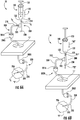
FIG. 6A is a prospective view of the biopsy assembly ofFIG. 1 shown in use operating in a suction mode; and -
FIG. 6B is a prospective view of the biopsy assembly ofFIG. 1 shown in use operating in a pressure mode. - Devices, systems, and methods for obtaining a tissue sample are provided in accordance with the present disclosure and described in detailed below. In particular, the present disclosure provides devices, systems, and methods that inhibit the loss of suction during tissue sampling procedures, obviate the need to expel any sample to regain suction should suction be lost, and provide an indication, e.g., audible and/or visual feedback, in the event of suction loss.
- With initial reference to
FIG. 1 , abiopsy assembly 10 provided in accordance with the present disclosure is shown generally including asuction device 100, avalve 200, and abiopsy catheter 300. Although the present disclosure will be described herein with reference to specific types of biopsy devices and procedures, namely endoscopic biopsy devices and procedures, it should be appreciated that the aspects and features of the present disclosure may be used in conjunction with any suitable biopsy or tissue sampling devices and procedures. - Continuing with reference to
FIG. 1 , it is envisioned thatsuction device 100 may take the form of any suitable device capable of creating a suction and pressure path, for example, a pump or syringe. For purposes herein,suction device 100 will be described as asyringe 100.Syringe 100 includes atubular housing 120 and aplunger 130 configured to be slidably received withintubular housing 120.Tubular housing 120 defines a connectingport 122 disposed at afirst end 121, an opensecond end 123, and anelongated cavity 126 therebetween.Connecting port 122 may be configured as a threaded shaft or threaded lumen, a male or female luer lock adaptor, or any other suitable structure configured to releasably mate with a counterpart device, such asvalve 200, as described below. -
Plunger 130 includes acircular portion 132 configured to be inserted intotubular housing 120 and ahandle 134 extending proximally therefrom. Withplunger 130 inserted intotubular housing 120, a fluid tight seal is created between a circumference ofcircular member 132 and an inner surface oftubular housing 120. It is envisioned thattubular housing 120 andcircular portion 132 be made from any suitable material and/or include suitable components to facilitate the creation of the fluid tight seal therebetween, e.g., by formingcircular portion 132 at least partially from a resiliently flexible material or providing an O-ring about the circumference ofcircular portion 132. Asplunger 130 slides withintubular housing 120 between first and second ends 121, 123 thereof, suction or pressure is created at connectingport 122, depending upon the direction of travel ofplunger 130 relative totubular housing 120. -
Tubular housing 120 may include one or more ergonomic features to facilitate gripping and manipulation ofplunger 130, such as ridge 128 which extends radially from opensecond end 123.Plunger 130 may further include a locking device (not shown) enabling the position ofplunger 130 with respect tofirst end 121 oftubular housing 120 to be fixed in one or more incremental positions, thereby maintaining a steady suction or pressure at connectingport 122 oftubular housing 120. - With reference to
FIG. 2 ,valve 200 is configured as a three-way directional-control valve defining afirst port 210, asecond port 220, athird port 230, and aflow controller 240.Valve 200 may define a "T" configuration, as illustrated inFIG. 2 , or may define any other suitable configuration such that first, second, andthird ports Valve 200 is configured to permit the flow of material through first, second, andthird ports third ports syringe 100,biopsy catheters 300, and a surgical tool, respectively. A variety of surgical tools, for example, biopsy needles, specimen collection tubes, hypodermic needles, connecting tubing, etc. may be configured to mate withthird port 230. First, second, andthird ports respective port -
Flow controller 240 is disposed withinvalve 200 and serves to selectively direct the flow of material throughsecond port 220 andthird port 230. Specifically, whileflow controller 240 permits the flow of material throughfirst port 210 in both directions, as indicated by arrows "A,"flow controller 240 serves to permit material to flow throughsecond port 220 only in the direction of arrow "B" intovalve 200 and serves to permit material to flow throughthird port 230 only in the direction of arrow "C" out ofvalve 200. Further,flow controller 240 is configured such that as material is expelled fromthird port 230,second port 220 is sealed off to inhibit expulsion of material fromsecond port 220 and maintain suction atsecond port 220. Such a feature is important in that it allows for the re-charging ofsyringe 100 without having to expel any portion of a tissue sample and without losing suction on the tissue sample, as described more fully below.Flow controller 240 may be configured as a duckbill valve, a check valve, a spool valve, or any other valve capable of providing the above-detailed features. - Referring again to
FIG. 1 ,biopsy catheter 300 includes aproximal end 310, adistal end 320, and defines a lumen extending therethrough.Proximal end 310 is configured to couple tosecond port 210 ofvalve 200 in any suitable fashion, e.g., threaded connection, luer lock, press-fit, etc.Distal end 320 ofbiopsy catheter 300 is configured to receive a tissue sample from target tissue "T" (FIGS. 6A and 6B ). It should be appreciated that withbiopsy catheter 300 coupled tovalve 200, a fluid-tight channel is established betweendistal end 320 ofbiopsy catheter 300 andsecond port 220 ofvalve 200 to enable a tissue sample to be suctioned intobiopsy catheter 300 by actuatingsuction device 100, e.g., movingplunger 130 relative totubular housing 120. - The
distal end 320 ofbiopsy catheter 300 may further be coupled to, or integrally formed with, atissue coring element 350.Tissue coring element 350 is configured to engage target tissue "T" (FIGS. 6A and 6B ) and facilitate the removal of a sample of the target tissue "T" (FIGS. 6A and 6B ). Thecoring component 350 may define a longitudinal lumen extending from aproximal region 352 and terminating in adistal opening 354. It should be appreciated that withbiopsy catheter 300 andtissue coring element 350 coupled, the respective lumens act cooperatively to define a single fluid-tight channel between thedistal opening 354 of thetissue coring element 350 and theproximal end 310 of thebiopsy catheter 300. Thecoring element 350 may be configured similar to any of the coring elements disclosed inU.S. Patent Application No. 14/564,779, filed on December 09, 2014 - With reference to
FIG. 3 , in some embodiments asample collection tube 500 configured for use withbiopsy assembly 10 is provided to collect and retain tissue samples captured bybiopsy assembly 10.Sample collection tube 500 includes aproximal end 510, adistal end 520, and defines a lumen therethrough.Sample collection tube 500 may be positioned betweenbiopsy catheter 300 andvalve 200 such that theproximal end 310 ofbiopsy catheter 300 is coupled to thedistal end 520 ofsample collection tube 500, and the proximal end 530 ofsample collection tube 500 is coupled tosecond port 220 ofvalve 200. It should be appreciated that withsample collection tube 500 coupled betweenbiopsy catheter 300 andvalve 200, a fluid-tight channel is established between thedistal end 320 of thebiopsy catheter 300 and thesecond port 220 of thevalve 200. Alternatively,sample collection tube 500 may be coupled tothird port 230 ofvalve 200.Sample collection tube 500 may be coupled tobiopsy catheter 300 andvalve 200 in any suitable fashion, such as those detailed above. - Referring to
FIGS. 1, 2, and 4 ,biopsy assembly 10 further includes one ormore indicators FIGS. 6A and 6B ) at thedistal end 320 ofbiopsy catheter 300. A loss of suction may occur if, for example, thedistal end 320 ofbiopsy catheter 300 is not maintained in approximation to the target tissue "T" (FIGS 6A and 6B ). The one ormore indicators distal end 320 ofbiopsy catheter 300 throughvalve 200 and intosyringe 100. Alternatively, the one ormore indicators valve 200, for example, betweenfirst port 210 andsecond port 220. - In embodiments, the indicator is an
audible indicator 610, as shown inFIG. 2 , that is configured to emit a whistle, siren, click, or any other suitable auditory notification upon a free flow of material therethrough, indicating a loss of suction, e.g., due to loss of approximation between thedistal end 320 ofbiopsy catheter 300 and the target tissue "T" (FIGS. 6A and 6B ). As seen inFIG. 4 , the indicator may additionally or alternatively include avisual indicator 620, such that, upon a free flow of material therethrough, a first visual pattern will change to a second, different visual pattern indicating to the user that suction has been lost. In embodiments, the first and second visual patterns are represented by different colors, written warnings, or any other suitable visual indicia.Visual indicator 620, as shown inFIG. 4 , is configured as an in-line flow indicator where thecolored segment 622 of therotatable wheel 624 turns in the direction of arrow "F" as material passes therethrough, visually indicating to the user that suction has been lost. - It is envisioned that a navigation tool, such as a navigation catheter, an endoscope, or any other articulatable surgical device, may be included to facilitate the positioning of the
distal end 320 ofbiopsy catheter 300. The navigation tool may be used as an avenue for guiding working tools, includingbiopsy catheter 300, into close approximation with target tissue "T" (FIGS. 6A and 6B ). In exemplary embodiments anavigation catheter 2000 is provided andbiopsy catheter 300 may be introduced into alumen 2010 ofnavigation catheter 2000. A locatable guide (LG) (not shown) may additionally be inserted into the navigation tool to facilitate approximation to the target tissue "T" (FIGS. 6A and 6B ). Alternatively,navigation catheter 2000,biopsy catheter 300, ortissue coring element 350 may have a sensor (not shown) embedded therein to enable tracking and navigation to the target "T" (FIGS. 6A and 6B ). Further, a fiber optic or other scope may be included to provide visual cues to the operator during a biopsy procedure. - With reference to
FIGS. 5-6B , the operation ofbiopsy assembly 10 is described. Initially, instep 1010, thedistal end 320 ofbiopsy catheter 300 is inserted into the target tissue "T" to be sampled. Prior to or after insertingbiopsy catheter 300 into position, theproximal end 310 ofbiopsy catheter 300 is coupled to thesecond port 220 ofvalve 200 andvalve 200 is coupled tosyringe 100. - In
step 1020, the syringe 100 (or other suitable suction apparatus) is operated in a suction move via slidably retractingplunger 130 from thefirst end 121 oftubular housing 120 to create a suction path defined from thedistal end 320 ofbiopsy catheter 300, through the lumen ofbiopsy catheter 300, throughsecond port 220, and throughfirst port 210 such that a tissue sample from the target tissue "T" is suctioned into thedistal end 320 of thebiopsy catheter 300. The suction path is indicated by arrows "S1," "S2," and "S2" as theplunger 130 is retracted in the direction of arrow "R" (FIG. 6A ). It is envisioned thatplunger 130 may be locked in one or more positions during retraction using the locking device (not shown) to fix the position ofplunger 130 with respect to thefirst end 121 oftubular housing 120 and maintain suction at thedistal end 320 ofbiopsy catheter 300. - During the suctioning of the tissue sample into
biopsy catheter 300, it is determined whether a loss of suction with the target tissue "T" has occurred, as indicated instep 1030. More specifically, by listening for an audible output fromindicator 610 and/orviewing indicator 620 for a visual output, the user can be alerted to the loss of suction, as detailed above. - Should suction be lost, as indicated in
step 1040,syringe 100 is put into a pressure mode to create a pressure path defined fromfirst port 210 ofvalve 200 tothird port 230 ofvalve 230, thereby expelling any material, e.g., air, drawn intosyringe 100 as a result of the loss of suction. The pressure mode ofsyringe 100 is accomplished by slidably movingplunger 130 towards thefirst end 121 oftubular housing 120, known as "recharging"plunger 130 ofsyringe 100. The pressure path is indicated by arrows "P1" and "P2" asplunger 130 is recharged in the direction of arrow "RE" ofFIG. 6B . Once recharging is complete and the air expelled fromsyringe 100, thedistal end 320 ofbiopsy catheter 300 can be repositioned within the target tissue "T" to regain suction, as indicated instep 1045. As detailed above, during the recharging ofplunger 130,valve 200 maintains suction atsecond port 220, thereby maintaining suction through the lumen ofbiopsy catheter 300 and inhibiting loss of tissue sample already collected. - In
step 1050, once suction is reestablished (or in instances where suction has not been lost),syringe 100 may be further operated in a similar fashion as described above to suction a sufficient amount of tissue sample intobiopsy catheter 300. Once a sufficient tissue sample has been acquired,biopsy catheter 300 may be removed from the patient, as indicated instep 1060. - Furthermore, while various embodiments of the present disclosure have been described above, it should be understood that they have been presented by way of example only, and not limitation.
Claims (10)
- A biopsy assembly (10) comprising:a biopsy catheter (300) including a proximal portion (310), a distal portion (320), and defining a lumen extending therethrough; anda valve (200) defining a first port (210), a second port (220), and an open third port (230), the first port configured to couple to a device (100) capable of applying suction and pressure to the valve, and the second port configured to couple to the proximal portion of the biopsy catheter (300),wherein the valve is configured such that, when suction is applied to the first port (210)a suction path is defined through the lumen of the biopsy catheter, the second port (220), and the first port for suctioning target tissue into the distal portion of the biopsy catheter, and such that, when pressure is applied to the first port a pressure path is defined through the first port and the third port (230) to expel material therethrough while maintaining suction at the second port;characterised in that the valve further includes an indicator (610, 620) configured to provide an audible or visual indication of loss of suction between the distal portion of the biopsy catheter and target tissue.
- The biopsy assembly of claim 1, wherein the indicator is an audible indicator (610) configured to produce an audible output when suction is lost between the distal portion of the biopsy catheter and target tissue.
- The biopsy assembly of claim 2, wherein the audible indicator (610) is a whistle.
- The biopsy assembly of claim 1, 2 or 3 wherein the indicator is a visual indicator (620) configured to produce a first visual output when suction is maintained between the distal portion of the biopsy catheter and target tissue and a second, different visual output when suction is lost between the distal portion of the biopsy catheter and target tissue.
- The biopsy assembly of claim 4, wherein the first and second visual outputs are different colors.
- The biopsy assembly of claim 1, 2, 2. 3, 4 or 5, wherein the distal portion (320) of the biopsy catheter is configured to penetrate target tissue and sever a tissue sample therefrom.
- The biopsy assembly of claim 1, 2, 3, 4 , 5 or 6. further including a coring component (350) including a proximal region configured to couple to the distal portion of the biopsy catheter, and a distal region configured to penetrate target tissue and sever a tissue sample therefrom.
- The biopsy assembly of claim 7, wherein each of the biopsy catheter and the coring component defines a continuous lumen therethrough.
- A system for obtaining a biopsy sample comprising:a biopsy assembly according to any preceding claim; anda device (100) capable of operating in a suction mode and a pressure mode coupled to the first port of the valve.
- The system of any one of claims 1 to 9, further comprising a tissue sample tube (500) disposed between the biopsy catheter and the valve, the tissue sample tube including a proximal portion (510) configured to couple to the second port (220) of the valve, and a distal portion (520) configured to couple to the proximal end of the biopsy catheter, the tissue sample tube (500) defining a lumen extending between the proximal portion and the distal portion, the lumen configured to capture the tissue sample therein.
Applications Claiming Priority (2)
| Application Number | Priority Date | Filing Date | Title |
|---|---|---|---|
| US201562149911P | 2015-04-20 | 2015-04-20 | |
| US15/018,407 US10695038B2 (en) | 2015-04-20 | 2016-02-08 | Devices, systems, and methods for obtaining a tissue sample |
Publications (2)
| Publication Number | Publication Date |
|---|---|
| EP3085309A1 EP3085309A1 (en) | 2016-10-26 |
| EP3085309B1 true EP3085309B1 (en) | 2020-01-01 |
Family
ID=55754184
Family Applications (1)
| Application Number | Title | Priority Date | Filing Date |
|---|---|---|---|
| EP16165259.9A Active EP3085309B1 (en) | 2015-04-20 | 2016-04-14 | Devices and systems for obtaining a tissue sample |
Country Status (3)
| Country | Link |
|---|---|
| US (1) | US10695038B2 (en) |
| EP (1) | EP3085309B1 (en) |
| CN (1) | CN106063713B (en) |
Families Citing this family (1)
| Publication number | Priority date | Publication date | Assignee | Title |
|---|---|---|---|---|
| US10610206B2 (en) * | 2017-08-09 | 2020-04-07 | Spiration, Inc. | Vacuum assisted sampling mechanism |
Family Cites Families (45)
| Publication number | Priority date | Publication date | Assignee | Title |
|---|---|---|---|---|
| US4051852A (en) * | 1975-06-26 | 1977-10-04 | The Kendall Company | Aspirating device |
| GB8610896D0 (en) | 1986-05-03 | 1986-06-11 | Needle Industries Ltd | Ophthalmic aspirating/irrigating device |
| US4785826A (en) | 1987-03-02 | 1988-11-22 | Ward John L | Biopsy instrument |
| US4944724A (en) * | 1987-06-05 | 1990-07-31 | Uresil Corporation | Apparatus for locating body cavities having signaling indicator |
| US4781202A (en) | 1987-08-31 | 1988-11-01 | Janese Woodrow W | Biopsy cannula |
| US4926877A (en) | 1989-04-24 | 1990-05-22 | Bookwalter John R | Biopsy needle with completely closable cutting end bore |
| US5074311A (en) | 1989-12-06 | 1991-12-24 | Hasson Harrith M | Biopsy device |
| US5183052A (en) | 1990-11-07 | 1993-02-02 | Terwilliger Richard A | Automatic biopsy instrument with cutting cannula |
| US5267572A (en) | 1990-11-20 | 1993-12-07 | Bucalo Brian D | Biopsy instrument with tissue specimen retaining and retrieval device |
| US5409453A (en) | 1992-08-12 | 1995-04-25 | Vidamed, Inc. | Steerable medical probe with stylets |
| US5133360A (en) | 1991-03-07 | 1992-07-28 | Spears Colin P | Spears retriever |
| EP1252863B1 (en) | 1993-09-20 | 2006-09-06 | Boston Scientific Corporation | Multiple biopsy sampling coring device |
| US5573008A (en) | 1993-10-29 | 1996-11-12 | Boston Scientific Corporation | Multiple biopsy sampling coring device |
| JPH09639A (en) | 1995-06-23 | 1997-01-07 | New Ueebu Medical:Kk | Coronary vein expander for ptca surgery |
| US5817034A (en) | 1995-09-08 | 1998-10-06 | United States Surgical Corporation | Apparatus and method for removing tissue |
| US5848978A (en) | 1995-11-14 | 1998-12-15 | Genx International, Inc. | Surgical biopsy device |
| US6007544A (en) | 1996-06-14 | 1999-12-28 | Beth Israel Deaconess Medical Center | Catheter apparatus having an improved shape-memory alloy cuff and inflatable on-demand balloon for creating a bypass graft in-vivo |
| CN2275431Y (en) | 1996-10-11 | 1998-03-04 | 湖南医科大学附属第三医院 | Fast single-hand biopsy gun |
| US6022324A (en) | 1998-01-02 | 2000-02-08 | Skinner; Bruce A. J. | Biopsy instrument |
| US6007495A (en) | 1998-01-22 | 1999-12-28 | United States Surgical Corporation | Biopsy apparatus and method |
| JP4157183B2 (en) | 1998-02-17 | 2008-09-24 | オリンパス株式会社 | Endoscopic treatment tool |
| JPH11225951A (en) | 1998-02-17 | 1999-08-24 | Olympus Optical Co Ltd | Treatment tool for endoscope |
| US6758848B2 (en) | 1998-03-03 | 2004-07-06 | Senorx, Inc. | Apparatus and method for accessing a body site |
| GB2338898A (en) | 1998-06-25 | 2000-01-12 | Dinuke Ramendra Warakaulle | Pleural aspiration kit |
| US6139508A (en) | 1998-08-04 | 2000-10-31 | Endonetics, Inc. | Articulated medical device |
| US6083237A (en) | 1998-10-23 | 2000-07-04 | Ethico Endo-Surgery, Inc. | Biopsy instrument with tissue penetrating spiral |
| JP4638051B2 (en) | 1999-03-19 | 2011-02-23 | ヴァイダケア、コーパレイシャン | Biopsy needle |
| US6248081B1 (en) | 1999-09-28 | 2001-06-19 | Scimed Life Systems, Inc. | Endoscopic submucosal core biopsy device |
| FR2802640B1 (en) | 1999-12-17 | 2003-01-03 | Pasteur Sanofi Diagnostics | DEVICE AND METHOD FOR COLLECTING A BIOLOGICAL SAMPLE |
| DE60124990T2 (en) | 2000-07-29 | 2007-09-20 | Worldwide Medical Technologies, Woodbury | Tool for extracting bone marrow |
| IT1316978B1 (en) | 2000-12-28 | 2003-05-13 | Hs Hospital Service Spa | DEVICE FOR TRANSCUTANEOUS BIOPSY OF RIGID TISSUES, IN PARTICULAR OSTEOMIDOLLAR TISSUE. |
| US7001342B2 (en) | 2001-10-30 | 2006-02-21 | Movdice Holding, Inc. | Biopsy/access tool with integrated biopsy device and access cannula and use thereof |
| US8425549B2 (en) * | 2002-07-23 | 2013-04-23 | Reverse Medical Corporation | Systems and methods for removing obstructive matter from body lumens and treating vascular defects |
| US7311673B2 (en) | 2003-04-24 | 2007-12-25 | Acueity, Inc. | Biopsy device |
| US7278970B2 (en) | 2003-07-29 | 2007-10-09 | Goldenberg Alec S | Biopsy needles |
| US7419472B2 (en) | 2003-09-30 | 2008-09-02 | Ethicon Endo-Surgery, Inc. | Biopsy instrument with internal specimen collection mechanism |
| US7517321B2 (en) * | 2005-01-31 | 2009-04-14 | C. R. Bard, Inc. | Quick cycle biopsy system |
| US8066717B2 (en) | 2007-03-19 | 2011-11-29 | Restoration Robotics, Inc. | Device and method for harvesting and implanting follicular units |
| EP2144569A4 (en) * | 2007-04-27 | 2014-03-26 | Cvdevices Llc | Devices, systems, and methods for accessing the epicardial surface of the heart |
| US20160361046A9 (en) | 2008-05-16 | 2016-12-15 | Covidien Lp | Biopsy device |
| US8449478B2 (en) | 2008-05-16 | 2013-05-28 | Conquest Medical Technologies | Biopsy device |
| US8529468B2 (en) | 2009-07-01 | 2013-09-10 | Suros Surgical Systems, Inc. | Surgical system |
| US8277394B2 (en) | 2009-08-18 | 2012-10-02 | Devicor Medical Products, Inc. | Multi-button biopsy device |
| US20140031772A1 (en) * | 2012-07-30 | 2014-01-30 | Next Healthcare, Inc. | System and method for collecting stem cells |
| US10390806B2 (en) | 2014-03-28 | 2019-08-27 | Covidien Lp | Devices, systems, and methods for obtaining a tissue sample using a biopsy tool |
-
2016
- 2016-02-08 US US15/018,407 patent/US10695038B2/en active Active
- 2016-04-14 EP EP16165259.9A patent/EP3085309B1/en active Active
- 2016-04-19 CN CN201610244053.7A patent/CN106063713B/en active Active
Non-Patent Citations (1)
| Title |
|---|
| None * |
Also Published As
| Publication number | Publication date |
|---|---|
| US10695038B2 (en) | 2020-06-30 |
| EP3085309A1 (en) | 2016-10-26 |
| US20160302778A1 (en) | 2016-10-20 |
| CN106063713B (en) | 2019-04-19 |
| CN106063713A (en) | 2016-11-02 |
Similar Documents
| Publication | Publication Date | Title |
|---|---|---|
| US10792022B2 (en) | Tissue sampling devices, systems and methods | |
| CN108934160B (en) | Shaft actuating handle | |
| CN100508897C (en) | Biopsy device incorporating an adjustable probe sleeve | |
| EP2382923B1 (en) | Pressure/vaccum actuated biopsy device | |
| US6190330B1 (en) | Endoscopic location and vacuum assembly and method | |
| US9226732B2 (en) | Bone marrow aspiration device and needle | |
| CN111655164B (en) | Biopsy device and method | |
| JP2006239434A (en) | Biopsy device incorporating adjustable probe sleeve | |
| CN111093463A (en) | Endoscope with a detachable handle | |
| US10058309B2 (en) | Medical instrument and medical system | |
| US20060058703A1 (en) | Optical biopsy instrument | |
| KR102404878B1 (en) | Endoscopic tool with suction to facilitate injection of fluid into the submucosal layer of tissue | |
| US11957308B2 (en) | Medical appliance for controlling medical device through catheter sheath based on pneumatic action | |
| US11484297B2 (en) | Liquid stylet apparatus | |
| EP3085309B1 (en) | Devices and systems for obtaining a tissue sample | |
| US20220249076A1 (en) | Needle handle with vacuum chamber | |
| US11324491B2 (en) | Click and release endobronchial specimen collection histology needle | |
| EP2866675B1 (en) | Fine needle aspiration biopsy device | |
| JP7315707B2 (en) | Biopsy needle and tissue sampling device | |
| CN116899070A (en) | catheter system |
Legal Events
| Date | Code | Title | Description |
|---|---|---|---|
| PUAI | Public reference made under article 153(3) epc to a published international application that has entered the european phase |
Free format text: ORIGINAL CODE: 0009012 |
|
| 17P | Request for examination filed |
Effective date: 20160414 |
|
| AK | Designated contracting states |
Kind code of ref document: A1 Designated state(s): AL AT BE BG CH CY CZ DE DK EE ES FI FR GB GR HR HU IE IS IT LI LT LU LV MC MK MT NL NO PL PT RO RS SE SI SK SM TR |
|
| AX | Request for extension of the european patent |
Extension state: BA ME |
|
| RIN1 | Information on inventor provided before grant (corrected) |
Inventor name: COSTELLO, DAVID Inventor name: MAGNUSON, THOMAS Inventor name: KERN, MICHAEL |
|
| RBV | Designated contracting states (corrected) |
Designated state(s): AL AT BE BG CH CY CZ DE DK EE ES FI FR GB GR HR HU IE IS IT LI LT LU LV MC MK MT NL NO PL PT RO RS SE SI SK SM TR |
|
| GRAP | Despatch of communication of intention to grant a patent |
Free format text: ORIGINAL CODE: EPIDOSNIGR1 |
|
| STAA | Information on the status of an ep patent application or granted ep patent |
Free format text: STATUS: GRANT OF PATENT IS INTENDED |
|
| RIN1 | Information on inventor provided before grant (corrected) |
Inventor name: MAGNUSON, THOMAS Inventor name: COSTELLO, DAVID Inventor name: KERN, MICHAEL |
|
| INTG | Intention to grant announced |
Effective date: 20190724 |
|
| GRAS | Grant fee paid |
Free format text: ORIGINAL CODE: EPIDOSNIGR3 |
|
| GRAA | (expected) grant |
Free format text: ORIGINAL CODE: 0009210 |
|
| STAA | Information on the status of an ep patent application or granted ep patent |
Free format text: STATUS: THE PATENT HAS BEEN GRANTED |
|
| AK | Designated contracting states |
Kind code of ref document: B1 Designated state(s): AL AT BE BG CH CY CZ DE DK EE ES FI FR GB GR HR HU IE IS IT LI LT LU LV MC MK MT NL NO PL PT RO RS SE SI SK SM TR |
|
| REG | Reference to a national code |
Ref country code: GB Ref legal event code: FG4D |
|
| REG | Reference to a national code |
Ref country code: CH Ref legal event code: EP Ref country code: AT Ref legal event code: REF Ref document number: 1218785 Country of ref document: AT Kind code of ref document: T Effective date: 20200115 |
|
| REG | Reference to a national code |
Ref country code: IE Ref legal event code: FG4D |
|
| REG | Reference to a national code |
Ref country code: DE Ref legal event code: R096 Ref document number: 602016027142 Country of ref document: DE |
|
| PGFP | Annual fee paid to national office [announced via postgrant information from national office to epo] |
Ref country code: GB Payment date: 20200323 Year of fee payment: 5 |
|
| REG | Reference to a national code |
Ref country code: NL Ref legal event code: MP Effective date: 20200101 |
|
| REG | Reference to a national code |
Ref country code: LT Ref legal event code: MG4D |
|
| PG25 | Lapsed in a contracting state [announced via postgrant information from national office to epo] |
Ref country code: FI Free format text: LAPSE BECAUSE OF FAILURE TO SUBMIT A TRANSLATION OF THE DESCRIPTION OR TO PAY THE FEE WITHIN THE PRESCRIBED TIME-LIMIT Effective date: 20200101 Ref country code: PT Free format text: LAPSE BECAUSE OF FAILURE TO SUBMIT A TRANSLATION OF THE DESCRIPTION OR TO PAY THE FEE WITHIN THE PRESCRIBED TIME-LIMIT Effective date: 20200527 Ref country code: NO Free format text: LAPSE BECAUSE OF FAILURE TO SUBMIT A TRANSLATION OF THE DESCRIPTION OR TO PAY THE FEE WITHIN THE PRESCRIBED TIME-LIMIT Effective date: 20200401 Ref country code: LT Free format text: LAPSE BECAUSE OF FAILURE TO SUBMIT A TRANSLATION OF THE DESCRIPTION OR TO PAY THE FEE WITHIN THE PRESCRIBED TIME-LIMIT Effective date: 20200101 Ref country code: CZ Free format text: LAPSE BECAUSE OF FAILURE TO SUBMIT A TRANSLATION OF THE DESCRIPTION OR TO PAY THE FEE WITHIN THE PRESCRIBED TIME-LIMIT Effective date: 20200101 Ref country code: NL Free format text: LAPSE BECAUSE OF FAILURE TO SUBMIT A TRANSLATION OF THE DESCRIPTION OR TO PAY THE FEE WITHIN THE PRESCRIBED TIME-LIMIT Effective date: 20200101 Ref country code: RS Free format text: LAPSE BECAUSE OF FAILURE TO SUBMIT A TRANSLATION OF THE DESCRIPTION OR TO PAY THE FEE WITHIN THE PRESCRIBED TIME-LIMIT Effective date: 20200101 |
|
| PG25 | Lapsed in a contracting state [announced via postgrant information from national office to epo] |
Ref country code: GR Free format text: LAPSE BECAUSE OF FAILURE TO SUBMIT A TRANSLATION OF THE DESCRIPTION OR TO PAY THE FEE WITHIN THE PRESCRIBED TIME-LIMIT Effective date: 20200402 Ref country code: IS Free format text: LAPSE BECAUSE OF FAILURE TO SUBMIT A TRANSLATION OF THE DESCRIPTION OR TO PAY THE FEE WITHIN THE PRESCRIBED TIME-LIMIT Effective date: 20200501 Ref country code: HR Free format text: LAPSE BECAUSE OF FAILURE TO SUBMIT A TRANSLATION OF THE DESCRIPTION OR TO PAY THE FEE WITHIN THE PRESCRIBED TIME-LIMIT Effective date: 20200101 Ref country code: LV Free format text: LAPSE BECAUSE OF FAILURE TO SUBMIT A TRANSLATION OF THE DESCRIPTION OR TO PAY THE FEE WITHIN THE PRESCRIBED TIME-LIMIT Effective date: 20200101 Ref country code: SE Free format text: LAPSE BECAUSE OF FAILURE TO SUBMIT A TRANSLATION OF THE DESCRIPTION OR TO PAY THE FEE WITHIN THE PRESCRIBED TIME-LIMIT Effective date: 20200101 Ref country code: BG Free format text: LAPSE BECAUSE OF FAILURE TO SUBMIT A TRANSLATION OF THE DESCRIPTION OR TO PAY THE FEE WITHIN THE PRESCRIBED TIME-LIMIT Effective date: 20200401 |
|
| REG | Reference to a national code |
Ref country code: DE Ref legal event code: R097 Ref document number: 602016027142 Country of ref document: DE |
|
| PG25 | Lapsed in a contracting state [announced via postgrant information from national office to epo] |
Ref country code: ES Free format text: LAPSE BECAUSE OF FAILURE TO SUBMIT A TRANSLATION OF THE DESCRIPTION OR TO PAY THE FEE WITHIN THE PRESCRIBED TIME-LIMIT Effective date: 20200101 Ref country code: RO Free format text: LAPSE BECAUSE OF FAILURE TO SUBMIT A TRANSLATION OF THE DESCRIPTION OR TO PAY THE FEE WITHIN THE PRESCRIBED TIME-LIMIT Effective date: 20200101 Ref country code: SM Free format text: LAPSE BECAUSE OF FAILURE TO SUBMIT A TRANSLATION OF THE DESCRIPTION OR TO PAY THE FEE WITHIN THE PRESCRIBED TIME-LIMIT Effective date: 20200101 Ref country code: EE Free format text: LAPSE BECAUSE OF FAILURE TO SUBMIT A TRANSLATION OF THE DESCRIPTION OR TO PAY THE FEE WITHIN THE PRESCRIBED TIME-LIMIT Effective date: 20200101 Ref country code: DK Free format text: LAPSE BECAUSE OF FAILURE TO SUBMIT A TRANSLATION OF THE DESCRIPTION OR TO PAY THE FEE WITHIN THE PRESCRIBED TIME-LIMIT Effective date: 20200101 Ref country code: SK Free format text: LAPSE BECAUSE OF FAILURE TO SUBMIT A TRANSLATION OF THE DESCRIPTION OR TO PAY THE FEE WITHIN THE PRESCRIBED TIME-LIMIT Effective date: 20200101 |
|
| PLBE | No opposition filed within time limit |
Free format text: ORIGINAL CODE: 0009261 |
|
| STAA | Information on the status of an ep patent application or granted ep patent |
Free format text: STATUS: NO OPPOSITION FILED WITHIN TIME LIMIT |
|
| REG | Reference to a national code |
Ref country code: AT Ref legal event code: MK05 Ref document number: 1218785 Country of ref document: AT Kind code of ref document: T Effective date: 20200101 |
|
| PG25 | Lapsed in a contracting state [announced via postgrant information from national office to epo] |
Ref country code: MC Free format text: LAPSE BECAUSE OF FAILURE TO SUBMIT A TRANSLATION OF THE DESCRIPTION OR TO PAY THE FEE WITHIN THE PRESCRIBED TIME-LIMIT Effective date: 20200101 |
|
| REG | Reference to a national code |
Ref country code: CH Ref legal event code: PL |
|
| 26N | No opposition filed |
Effective date: 20201002 |
|
| PG25 | Lapsed in a contracting state [announced via postgrant information from national office to epo] |
Ref country code: AT Free format text: LAPSE BECAUSE OF FAILURE TO SUBMIT A TRANSLATION OF THE DESCRIPTION OR TO PAY THE FEE WITHIN THE PRESCRIBED TIME-LIMIT Effective date: 20200101 Ref country code: LU Free format text: LAPSE BECAUSE OF NON-PAYMENT OF DUE FEES Effective date: 20200414 Ref country code: CH Free format text: LAPSE BECAUSE OF NON-PAYMENT OF DUE FEES Effective date: 20200430 Ref country code: LI Free format text: LAPSE BECAUSE OF NON-PAYMENT OF DUE FEES Effective date: 20200430 Ref country code: IT Free format text: LAPSE BECAUSE OF FAILURE TO SUBMIT A TRANSLATION OF THE DESCRIPTION OR TO PAY THE FEE WITHIN THE PRESCRIBED TIME-LIMIT Effective date: 20200101 |
|
| REG | Reference to a national code |
Ref country code: BE Ref legal event code: MM Effective date: 20200430 |
|
| PG25 | Lapsed in a contracting state [announced via postgrant information from national office to epo] |
Ref country code: PL Free format text: LAPSE BECAUSE OF FAILURE TO SUBMIT A TRANSLATION OF THE DESCRIPTION OR TO PAY THE FEE WITHIN THE PRESCRIBED TIME-LIMIT Effective date: 20200101 Ref country code: SI Free format text: LAPSE BECAUSE OF FAILURE TO SUBMIT A TRANSLATION OF THE DESCRIPTION OR TO PAY THE FEE WITHIN THE PRESCRIBED TIME-LIMIT Effective date: 20200101 Ref country code: BE Free format text: LAPSE BECAUSE OF NON-PAYMENT OF DUE FEES Effective date: 20200430 |
|
| PG25 | Lapsed in a contracting state [announced via postgrant information from national office to epo] |
Ref country code: IE Free format text: LAPSE BECAUSE OF NON-PAYMENT OF DUE FEES Effective date: 20200414 |
|
| PGFP | Annual fee paid to national office [announced via postgrant information from national office to epo] |
Ref country code: FR Payment date: 20210323 Year of fee payment: 6 |
|
| PGFP | Annual fee paid to national office [announced via postgrant information from national office to epo] |
Ref country code: DE Payment date: 20210323 Year of fee payment: 6 |
|
| GBPC | Gb: european patent ceased through non-payment of renewal fee |
Effective date: 20210414 |
|
| PG25 | Lapsed in a contracting state [announced via postgrant information from national office to epo] |
Ref country code: GB Free format text: LAPSE BECAUSE OF NON-PAYMENT OF DUE FEES Effective date: 20210414 |
|
| PG25 | Lapsed in a contracting state [announced via postgrant information from national office to epo] |
Ref country code: TR Free format text: LAPSE BECAUSE OF FAILURE TO SUBMIT A TRANSLATION OF THE DESCRIPTION OR TO PAY THE FEE WITHIN THE PRESCRIBED TIME-LIMIT Effective date: 20200101 Ref country code: MT Free format text: LAPSE BECAUSE OF FAILURE TO SUBMIT A TRANSLATION OF THE DESCRIPTION OR TO PAY THE FEE WITHIN THE PRESCRIBED TIME-LIMIT Effective date: 20200101 Ref country code: CY Free format text: LAPSE BECAUSE OF FAILURE TO SUBMIT A TRANSLATION OF THE DESCRIPTION OR TO PAY THE FEE WITHIN THE PRESCRIBED TIME-LIMIT Effective date: 20200101 |
|
| PG25 | Lapsed in a contracting state [announced via postgrant information from national office to epo] |
Ref country code: MK Free format text: LAPSE BECAUSE OF FAILURE TO SUBMIT A TRANSLATION OF THE DESCRIPTION OR TO PAY THE FEE WITHIN THE PRESCRIBED TIME-LIMIT Effective date: 20200101 Ref country code: AL Free format text: LAPSE BECAUSE OF FAILURE TO SUBMIT A TRANSLATION OF THE DESCRIPTION OR TO PAY THE FEE WITHIN THE PRESCRIBED TIME-LIMIT Effective date: 20200101 |
|
| REG | Reference to a national code |
Ref country code: DE Ref legal event code: R119 Ref document number: 602016027142 Country of ref document: DE |
|
| PG25 | Lapsed in a contracting state [announced via postgrant information from national office to epo] |
Ref country code: FR Free format text: LAPSE BECAUSE OF NON-PAYMENT OF DUE FEES Effective date: 20220430 Ref country code: DE Free format text: LAPSE BECAUSE OF NON-PAYMENT OF DUE FEES Effective date: 20221103 |