EP3085296A1 - Insertion device - Google Patents
Insertion device Download PDFInfo
- Publication number
- EP3085296A1 EP3085296A1 EP14872393.5A EP14872393A EP3085296A1 EP 3085296 A1 EP3085296 A1 EP 3085296A1 EP 14872393 A EP14872393 A EP 14872393A EP 3085296 A1 EP3085296 A1 EP 3085296A1
- Authority
- EP
- European Patent Office
- Prior art keywords
- displacement
- section
- optical fiber
- displacement restraint
- core
- Prior art date
- Legal status (The legal status is an assumption and is not a legal conclusion. Google has not performed a legal analysis and makes no representation as to the accuracy of the status listed.)
- Withdrawn
Links
- 238000003780 insertion Methods 0.000 title claims abstract description 35
- 230000037431 insertion Effects 0.000 title claims abstract description 35
- 238000006073 displacement reaction Methods 0.000 claims abstract description 149
- 239000013307 optical fiber Substances 0.000 claims abstract description 125
- 239000011248 coating agent Substances 0.000 claims abstract description 57
- 238000000576 coating method Methods 0.000 claims abstract description 57
- 238000005253 cladding Methods 0.000 claims abstract description 56
- 238000001514 detection method Methods 0.000 claims abstract description 40
- 239000000853 adhesive Substances 0.000 claims description 16
- 230000001070 adhesive effect Effects 0.000 claims description 16
- 239000006096 absorbing agent Substances 0.000 claims description 12
- 239000000463 material Substances 0.000 claims description 5
- 230000000452 restraining effect Effects 0.000 claims description 4
- 238000005286 illumination Methods 0.000 description 8
- 230000003287 optical effect Effects 0.000 description 5
- 230000004927 fusion Effects 0.000 description 3
- 238000006243 chemical reaction Methods 0.000 description 2
- 230000007423 decrease Effects 0.000 description 2
- 230000003247 decreasing effect Effects 0.000 description 2
- 238000010586 diagram Methods 0.000 description 2
- 238000010521 absorption reaction Methods 0.000 description 1
- 230000000694 effects Effects 0.000 description 1
- 238000010438 heat treatment Methods 0.000 description 1
- 238000012986 modification Methods 0.000 description 1
- 230000004048 modification Effects 0.000 description 1
- 230000002093 peripheral effect Effects 0.000 description 1
- 239000011347 resin Substances 0.000 description 1
- 229920005989 resin Polymers 0.000 description 1
- 239000000523 sample Substances 0.000 description 1
- 230000035945 sensitivity Effects 0.000 description 1
- 239000007779 soft material Substances 0.000 description 1
Images






Classifications
-
- G—PHYSICS
- G02—OPTICS
- G02B—OPTICAL ELEMENTS, SYSTEMS OR APPARATUS
- G02B23/00—Telescopes, e.g. binoculars; Periscopes; Instruments for viewing the inside of hollow bodies; Viewfinders; Optical aiming or sighting devices
- G02B23/24—Instruments or systems for viewing the inside of hollow bodies, e.g. fibrescopes
- G02B23/2476—Non-optical details, e.g. housings, mountings, supports
-
- A—HUMAN NECESSITIES
- A61—MEDICAL OR VETERINARY SCIENCE; HYGIENE
- A61B—DIAGNOSIS; SURGERY; IDENTIFICATION
- A61B1/00—Instruments for performing medical examinations of the interior of cavities or tubes of the body by visual or photographical inspection, e.g. endoscopes; Illuminating arrangements therefor
- A61B1/00163—Optical arrangements
- A61B1/00165—Optical arrangements with light-conductive means, e.g. fibre optics
-
- A—HUMAN NECESSITIES
- A61—MEDICAL OR VETERINARY SCIENCE; HYGIENE
- A61B—DIAGNOSIS; SURGERY; IDENTIFICATION
- A61B1/00—Instruments for performing medical examinations of the interior of cavities or tubes of the body by visual or photographical inspection, e.g. endoscopes; Illuminating arrangements therefor
- A61B1/005—Flexible endoscopes
- A61B1/009—Flexible endoscopes with bending or curvature detection of the insertion part
-
- G—PHYSICS
- G01—MEASURING; TESTING
- G01B—MEASURING LENGTH, THICKNESS OR SIMILAR LINEAR DIMENSIONS; MEASURING ANGLES; MEASURING AREAS; MEASURING IRREGULARITIES OF SURFACES OR CONTOURS
- G01B11/00—Measuring arrangements characterised by the use of optical techniques
- G01B11/16—Measuring arrangements characterised by the use of optical techniques for measuring the deformation in a solid, e.g. optical strain gauge
- G01B11/18—Measuring arrangements characterised by the use of optical techniques for measuring the deformation in a solid, e.g. optical strain gauge using photoelastic elements
-
- G—PHYSICS
- G01—MEASURING; TESTING
- G01B—MEASURING LENGTH, THICKNESS OR SIMILAR LINEAR DIMENSIONS; MEASURING ANGLES; MEASURING AREAS; MEASURING IRREGULARITIES OF SURFACES OR CONTOURS
- G01B11/00—Measuring arrangements characterised by the use of optical techniques
- G01B11/24—Measuring arrangements characterised by the use of optical techniques for measuring contours or curvatures
-
- G—PHYSICS
- G02—OPTICS
- G02B—OPTICAL ELEMENTS, SYSTEMS OR APPARATUS
- G02B23/00—Telescopes, e.g. binoculars; Periscopes; Instruments for viewing the inside of hollow bodies; Viewfinders; Optical aiming or sighting devices
- G02B23/24—Instruments or systems for viewing the inside of hollow bodies, e.g. fibrescopes
- G02B23/2407—Optical details
- G02B23/2461—Illumination
- G02B23/2469—Illumination using optical fibres
-
- A—HUMAN NECESSITIES
- A61—MEDICAL OR VETERINARY SCIENCE; HYGIENE
- A61B—DIAGNOSIS; SURGERY; IDENTIFICATION
- A61B34/00—Computer-aided surgery; Manipulators or robots specially adapted for use in surgery
- A61B34/20—Surgical navigation systems; Devices for tracking or guiding surgical instruments, e.g. for frameless stereotaxis
- A61B2034/2046—Tracking techniques
- A61B2034/2061—Tracking techniques using shape-sensors, e.g. fiber shape sensors with Bragg gratings
Definitions
- Patent Literature 1 discloses an endoscope into which a curved-shape detection sensor is incorporated, wherein the curved-shape detection sensor includes a plurality of sensing parts for detecting a curved shape.
- the curved-shape detection sensor includes optical fibers including a core onto which light absorbers are formed only in a predetermined direction at portions from which a cladding is exposed.
- the curved-shape detection sensor detects a curved shape of the endoscope on the basis of the fact that the amount of light guided through the optical fibers varies with the curved angle and curved direction of the optical fibers.
- the curved direction is determined by means of a sensing part according to a light absorber which is formed in a predetermined direction.
- the optical fibers are not fixed to the proximal end of the endoscope and extend to cause a small wave such that they cannot be easily broken even though curvature appears repeatedly.
- FIG. 1 is a diagram showing the overall configuration of an endoscope apparatus 1.
- the endoscope apparatus 1 includes an endoscope 10 into which a curved-shape detection sensor 100 is incorporated, an apparatus main body 20 connected to the endoscope 10, and a display unit 30 connected to the apparatus main body 20.
- the apparatus main body 20 includes a light-emitting unit 21 that supplies light to the curved-shape detection sensor 100, a light-receiving unit 22 that receives light returned from the curved-shape detection sensor 100, and a computation unit 23 that computes a curved shape of a curved portion 14 (described later) of the endoscope 10 on the basis of the amount of light received by the light-receiving unit 22.
- the apparatus main body 20 also includes, for example, a control unit that controls a predetermined function of one or more peripheral devices including the endoscope 10, which is connected to the apparatus main body 20.
- the internal component for fixing the optical fibers 101 is not limited to the channel tube 17 but may include a component that is displaced along the curve of the insert section 11, such as the optical fiber 18 for illumination light and the wiring 19 for image pickup elements, or a component that is curved along with the insert section 11.
- the light-emitting unit 21 that emits and guides light through the optical fiber 101 and the light-receiving unit 22 that receives light guided through the optical fiber 101 are connected to the proximal end of the optical fiber 101.
- the light-emitting unit 21 and the light-receiving unit 22 are disposed in the apparatus main body 20; however, they can be disposed separately from the apparatus main body 20, disposed in the endoscope 10, or the like.
- a mirror 107 is disposed at the distal end of the optical fiber 101 (see FIGS. 24-26 ).
- paired sensing parts 105a and 105b are respectively formed on two optical fibers 101a and 101b of the optical fibers 101 in the X-axis and Y-axis directions shown in FIG. 2 in order to detect curved shapes in two directions orthogonal to the longitudinal direction (insertion direction) and perpendicular to each other, namely, in the X-axis and Y-axis directions.
- a plurality of optical fibers 101 are disposed in such a manner that the paired sensing parts 105a and 105b are located in the same position in the longitudinal direction of the insert section 11.
- FIGS. 4A-4C are schematic views showing light passing by the sensing part 105 of the optical fiber 101.
- the sensing part 105 When the optical fiber 101 is straight, light guided through the optical fiber 101 is partly absorbed by the light absorber of the sensing part 105 ( FIG. 4A ).
- the sensing part 105 When the sensing part 105 is curved inwardly, light applied to the sensing part 105 decreases and thus the amount of light absorbed by the sensing part 105 becomes small ( FIG. 4B ). In other words, the amount of light transmitted through the optical fiber 101 becomes large.
- the sensing part 105 when the sensing part 105 is curved outwardly, light applied to the sensing part 105 increases and thus the amount of light absorbed by the sensing part 105 becomes large ( FIG. 4C ). In other words, the amount of light transmitted through the optical fiber 101 becomes small.
- the sensing part 105 contributes to detect an amount of curvature on the basis of the amount of light transmitted through the optical fiber 101 in accordance
- the display unit 30 is detachably connected to the apparatus main body 20.
- the display unit 30 displays an image in the insertion target 200 picked up by the endoscope 10 and a curved shape of the insert section 11 computed by the computation unit 23.
- the displacement restraint section 106 need not be adhered by an adhesive. If two members are chemically combined, the displacement restraint section 106 can be adhered by a mixed layer formed by deriving from the materials of the core 102 and the channel tube 17. Or, the core 102 and the channel tube 17 can be mechanically fixed to restrain the displacement of the core 102 by not only the adhesion but also pressing, absorption, fusion described later, or the like. In FIGS.
- the sensing part 105 is located in a position distant from the position of the displacement restraint section 106 in the longitudinal direction of the optical fiber 101, it is likely that the optical fiber 101 will be twisted and the sensing part 105 will rotate with respect to the displacement restraint section 106. In other words, the sensing part 105 is likely to rotate with respect to the insert section 11, which lowers detection precision of an amount of curvature. It is thus desirable that the displacement restraint section 106 be located in the same position as that of the sensing part 105 in the longitudinal direction of the optical fiber 101 or close to the sensing part within a range that allows the sensing part 105 to be rotated by the twist.
- the detection precision of the amount of curvature can be improved.
- FIGS. 12A-12C are schematic longitudinal sectional views showing an optical fiber 101 fixed to the channel tube 17.
- the coating 104 and the cladding 103 are partly removed to form an opening, and the core 102 and the channel tube 17 are brought into direct contact with each other by the displacement restraint section 106 to restrain the displacement of the core 102 relative to the channel tube 17.
- the cladding 103 is left and the coating 104 is partly removed to form an opening, and the opening is filled with an adhesive to form the displacement restraint section 106, with the result that the cladding 103 and the channel tube 17 can be adhered to each other.
- the core 102 and the cladding 103 are brought into intimate contact without moving to each other, the cladding 103 and the coating 104 are adhered by the displacement restraint section 106b, and the channel tube 17 and the coating 104 are adhered by the displacement restraint section 106a.
- the displacement of the core 102 relative to the channel tube 17 can indirectly be restrained via the cladding 103 and the coating 104. If an opening is formed in the coating 104 and the cladding 103, the strength of the optical fiber 101 decreases; however, in this configuration, no opening is formed and the displacement restraint sections 106a and 106b can be formed without decreasing the strength of the optical fiber 101.
- an adhesive is injected by, e.g. an injector.
- the cladding 103 and the coating 104 can be adhered by forming an opening in the coating 104 in a position other than the position in which the coating 104 is adhered to the channel tube 17, injecting an adhesive whose viscosity is low from the opening, and causing the adhesive to spread between the cladding 103 and the coating 104.
- the coating 104 is opened by applying external energy of, e.g. a laser and heating, and the cladding 103 is partly cut to fuse the coating 104 and the cladding 103 together.
- the displacement restraint section 108 is formed by the fusion and accordingly the coating 104 and the cladding 103 are formed integrally with each other.
- the coating 104 and the channel tube 17 are adhered by the displacement restraint section 106a. Therefore, the coating 104 and the cladding 103 can be adhered without using an adhesive as the displacement restraint section 106b.
- the displacement restraint section 106a (displacement restraint section 106) between the channel tube 17 and the coating 104 and the displacement restraint section 106b (displacement restraint section 108) between the cladding 103 and the coating 104 need not be formed in the same position in the longitudinal direction of the optical fiber 101, but can be formed in different positions or can partly overlap each other if they are fall within a range that allows the sensing part 105 to be rotated by twist of the optical fiber 101.
- a plurality of displacement restraint sections 106a can be present between the channel tube 17 and the coating 104 as shown in FIG. 20 if the optical fiber 101 is not damaged by tension applied thereto.
- a plurality of displacement restraint sections 106b can also be present.
- both displacement restraint sections 106a and 106b can also be present.
- the sensing part 105 and the displacement restraint section 106 can be formed integrally with each other, the sensing part 105 and the displacement restraint section 106 can be formed by partly removing the coating 104 and the cladding 103 to form an opening and partly cutting the core 102 in the radial direction of the opening, as shown in FIGS. 22 and 23 .
- the amount of light absorbed by the sensing part 105 increases and thus detection sensitivity to the amount of curvature can be improved.
- a mirror 107 is disposed at the side end portion of the optical fiber 101 to reflect light guided through the core 102. It is desirable that the mirror 107 be protected by, e.g. resin because it easily comes off and is damaged due to an external force. As shown in FIG. 26 , therefore, the cladding 103 and the coating 104 can be adhered by applying an adhesive to cover the mirror 107 to form a displacement restraint section 106, and a displacement restraint section 106 can be formed at a different position to adhere the coating 104 and the channel tube 17. It is thus possible to fulfill a displacement restraint function and a mirror protection function at once by adhesion of the displacement restraint section 106.
- one sensing part 105 is provided for one optical fiber 105; however, a plurality of sensing part 105 can be provided for one optical fiber 101.
- a plurality of sensing parts 105 are formed by applying light absorbers having different wavelength characteristics, the amount of light of different wavelengths varies with a curved state of each sensing part 105. It is thus possible to detect a variation in the amount of light of each wavelength and compute the amount of curvature of its corresponding sensing part 105.
- the displacement of, e.g. a core can be restrained directly or indirectly by the displacement restraint section 106 for the internal components of the insert section 11, for example, the cylindrical channel tube 17, the optical fiber 18 the wiring 19 for image pickup elements, and the like. However, it can be restrained using pieces 111 as shown in FIG. 28 .
- FIG. 28 is a schematic view showing a displacement restraint mechanism using liner tubes 110 and pieces 111.
- One of the two pieces 111 is disposed before a sensing part 105 and the other piece 111 is disposed after the sensing part 105, and the displacement of one of the pieces 111 relative to the core 102 is restrained directly or indirectly by the displacement restraint section 106.
- the displacement restraint section 106 may have any one of the configurations shown in FIGS. 12A-12C .
- the other piece 111 is not provided with a displacement restraint section 106 to prevent tension from being applied to the optical fiber 101 by the curvature, but the optical fiber 101 is disposed slidably with respect to the pieces 111.
- the pieces 111 are each screwed into the liner tube 110 by a screw 112.
- the liner tube 110 is a spiral, metallic tube.
Landscapes
- Physics & Mathematics (AREA)
- Optics & Photonics (AREA)
- Health & Medical Sciences (AREA)
- Life Sciences & Earth Sciences (AREA)
- General Physics & Mathematics (AREA)
- Surgery (AREA)
- Astronomy & Astrophysics (AREA)
- Biomedical Technology (AREA)
- Animal Behavior & Ethology (AREA)
- Engineering & Computer Science (AREA)
- Pathology (AREA)
- Heart & Thoracic Surgery (AREA)
- Medical Informatics (AREA)
- Molecular Biology (AREA)
- Radiology & Medical Imaging (AREA)
- General Health & Medical Sciences (AREA)
- Public Health (AREA)
- Veterinary Medicine (AREA)
- Nuclear Medicine, Radiotherapy & Molecular Imaging (AREA)
- Biophysics (AREA)
- Endoscopes (AREA)
- Instruments For Viewing The Inside Of Hollow Bodies (AREA)
Abstract
Description
- The present invention relates to an insertion apparatus into which a curved-shape detection sensor is incorporated.
- It is known to incorporate a curved-shape detection sensor into an insertion apparatus (e.g. an endoscope) including an elongated insert section to be inserted into an insertion target and detect a curved shape (a curved angle and a curved direction) thereof.
- For example, Patent Literature 1 discloses an endoscope into which a curved-shape detection sensor is incorporated, wherein the curved-shape detection sensor includes a plurality of sensing parts for detecting a curved shape. The curved-shape detection sensor includes optical fibers including a core onto which light absorbers are formed only in a predetermined direction at portions from which a cladding is exposed. The curved-shape detection sensor detects a curved shape of the endoscope on the basis of the fact that the amount of light guided through the optical fibers varies with the curved angle and curved direction of the optical fibers. The curved direction is determined by means of a sensing part according to a light absorber which is formed in a predetermined direction. The optical fibers are not fixed to the proximal end of the endoscope and extend to cause a small wave such that they cannot be easily broken even though curvature appears repeatedly.
- Patent Literature 1: Jpn. Pat. Appln. KOKAI Publication No.
2003-52612 - In a curved-shape detection sensor including light absorbers formed only in a predetermined direction, such as an insertion apparatus disclosed in Patent Literature 1, a curved direction to be detected by the curved-shape detection sensor and an intended curved direction to be detected have to coincide with each other. Accordingly, when the curved-shape detection sensor is incorporated into an insertion apparatus, it is necessary to fix the curved-shape detection sensor into the insertion apparatus to prevent positions of sensing parts of the curved-shape detection sensor from varying in relation to the insertion apparatus by movement of the insertion apparatus.
- However, Patent Literature 1 fails to disclose how the curved-shape detection sensor is incorporated into the insertion apparatus and, in this Patent Literature, it is likely that detection precision of a curved shape will be lowered due to variations in position of sensing parts in relation to the insertion apparatus.
- It is therefore an object of the present invention to provide an insertion apparatus capable of restraining variations in position of sensing parts in relation to the insertion apparatus to improve detection precision of a curved shape.
- One embodiment of the present invention is an insertion apparatus including a flexible insert section to be inserted into an insertion target; and a curved-shape detection sensor which detects a curved shape of the insert section, characterized in that the curved-shape detection sensor includes at least a core, a cladding covering the core, a coating covering the cladding, and a sensing part mechanically attached to the core and which contributes to detect the curved shape, the optical fiber is disposed at least in the insert section, and the optical fiber includes at least one displacement restraint section which directly or indirectly restrains a displacement of the sensing part relative to the insert section. Advantageous Effects of Invention
- According to the present invention, there can be provided an insertion apparatus capable of restraining variations in position of a sensing part in relation to the insertion apparatus to improve detection precision of a curved shape.
-
-
FIG. 1 is a diagram showing the overall configuration of an endoscope apparatus. -
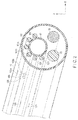
FIG. 2 is a perspective view showing the inside of an insert section of the endoscope. -
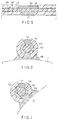
FIG. 3 is a cross-sectional view of an optical fiber that constitutes a curved-shape detection sensor. -
FIG. 4A is an illustration of one example of light passing by a sensing part of the optical fiber. -
FIG. 4B is an illustration of one example of light passing by a sensing part of the optical fiber. -
FIG. 4C is an illustration of one example of light passing by a sensing part of the optical fiber. -
FIG. 5 is a longitudinal sectional view showing an optical fiber fixed to a channel tube by a displacement restraint section. -
FIG. 6 is a cross-sectional view showing the optical fiber fixed to the channel tube by the displacement restraint section. -
FIG. 7 is a cross-sectional view showing the optical fiber fixed to the channel tube by the displacement restraint section. -
FIG. 8 is a longitudinal sectional view showing a relationship in position between the displacement restraint section and the sensing part in the longitudinal direction of the optical fiber. -
FIG. 9 is a longitudinal sectional view showing an optical fiber fixed to a channel tube by a plurality of displacement restraint sections. -
FIG. 10 is a longitudinal sectional view showing an optical fiber provided with a sensing part whose thickness is equal to or smaller than that of a cladding. -
FIG. 11 is a cross-sectional view showing the optical fiber provided with a sensing part whose thickness is equal to or smaller than that of a cladding. -
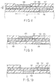
FIG. 12A is a schematic longitudinal sectional view showing an optical fiber fixed to a channel tube by a displacement restraint section. -
FIG. 12B is a schematic longitudinal sectional view showing an optical fiber fixed to a channel tube by a displacement restraint section. -
FIG. 12C is a schematic longitudinal sectional view showing an optical fiber fixed to a channel tube by displacement restraint sections. -
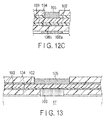
FIG. 13 is a longitudinal sectional view showing an optical fiber fixed to a channel tube by a displacement restraint section. -
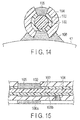
FIG. 14 is a cross-sectional view showing an optical fiber fixed to a channel tube by a displacement restraint section. -
FIG. 15 is a longitudinal sectional view showing an optical fiber fixed to a channel tube by displacement restraint sections. -
FIG. 16A is a longitudinal sectional view showing an optical fiber fixed to a channel tube by displacement restraint sections. -
FIG. 16B is a longitudinal sectional view showing an optical fiber fixed to a channel tube by displacement restraint sections. -
FIG. 17 is a cross-sectional view showing an optical fiber fixed to a channel tube by displacement restraint sections. -
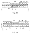
FIG. 18 is a longitudinal sectional view showing an optical fiber fixed to a channel tube by displacement restraint sections. -
FIG. 19 is a longitudinal sectional view showing a relationship in position between two displacement restraint sections in the longitudinal direction of the optical fiber. -
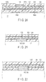
FIG. 20 is a longitudinal sectional view showing an optical fiber fixed to a channel tube by a plurality of displacement restraint sections. -
FIG. 21 is a longitudinal sectional view showing an optical fiber in which a sensing part and a displacement restraint section are formed integrally as one unit. -
FIG. 22 is a longitudinal sectional view showing an optical fiber in which a sensing part and a displacement restraint section are formed integrally as one unit. -
FIG. 23 is a cross-sectional view showing an optical fiber in which a sensing part and a displacement restraint section are formed integrally as one unit. -
FIG. 24 is a longitudinal sectional view showing an optical fiber fixed to a channel tube by a displacement restraint section at a distal end of an optical fiber. -
FIG. 25 is a longitudinal sectional view showing an optical fiber fixed to a channel tube by a displacement restraint section at a distal end of an optical fiber. -
FIG. 26 is a longitudinal sectional view showing an optical fiber fixed to a channel tube by a displacement restraint section at a distal end of an optical fiber. -
FIG. 27 is a longitudinal side view showing an optical fiber bent between one sensing part and its corresponding displacement restraint section and other sensing part and its corresponding displacement restraint section. -
FIG. 28 is a schematic view showing a displacement restraint mechanism using liner tubes and pieces. - Embodiments of the present invention will be described below with reference to the drawings. Hereinafter, an endoscope will be described as one example of an insertion apparatus; however, the insertion apparatus is not limited to the endoscope but includes, for example, a catheter, forceps and a treatment tool.
-
FIG. 1 is a diagram showing the overall configuration of an endoscope apparatus 1. The endoscope apparatus 1 includes anendoscope 10 into which a curved-shape detection sensor 100 is incorporated, an apparatusmain body 20 connected to theendoscope 10, and adisplay unit 30 connected to the apparatusmain body 20. The apparatusmain body 20 includes a light-emittingunit 21 that supplies light to the curved-shape detection sensor 100, a light-receivingunit 22 that receives light returned from the curved-shape detection sensor 100, and acomputation unit 23 that computes a curved shape of a curved portion 14 (described later) of theendoscope 10 on the basis of the amount of light received by the light-receivingunit 22. Though not shown, the apparatusmain body 20 also includes, for example, a control unit that controls a predetermined function of one or more peripheral devices including theendoscope 10, which is connected to the apparatusmain body 20. - The
endoscope 10 includes aflexible insert section 11 to be inserted into aninsertion target 200, an operation unitmain body 12 coupled to the proximal end of theinsert section 11, and acord section 13 extending from the operation unitmain body 12 and includingoptical fibers 101, anoptical fiber 18 for illumination light andwiring 19 for image pickup elements, which will be describe later. Theendoscope 10 is detachably connected to the apparatusmain body 20 via thecord section 13 to communicate with the apparatusmain body 20. - The
insert section 11 is a long and narrow tubular portion on the distal-end side of the endoscope. Theinsert section 11 includes acurved portion 14 on its distal-end side and an elongated flexibletubular portion 15 on its proximal-end side. Though not shown, the distal end of theinsert section 11 contains, for example, an observation optical system including an objective lens, an image pickup element which forms an optical image from the observation optical system and converts it into an electrical signal, and an illumination optical system including an illumination lens. Thecurved portion 14 is curved in a desired direction if an operator manually operates anoperation knob 16 disposed on the operation unitmain body 12. The flexibletubular portion 15 is curved along the curved shape of theinsertion target 200. -
FIG. 2 is a perspective view showing the inside of theinsert section 11. Internal components are incorporated inside theinsert section 11, such as acylindrical channel tube 17 through which a treatment tool such as an ultrasonic probe and forceps, passes, anoptical fiber 18 for illumination light which transmits illumination light to the illumination optical system, andwiring 19 for image pickup elements. Furthermore, a curved-shape detection sensor 100 is incorporated inside theinsert section 11 to detect a curved shape of theinsert section 11. The curved-shape detection sensor 100 includes a plurality ofoptical fibers 101, and theseoptical fibers 101 are arranged at least in theinsert section 11. In this embodiment, theoptical fibers 101 are fixed onto the outer surface of thechannel tube 17 bydisplacement restraint sections 106 described later. - Of the internal components of the
insert section 11, thechannel tube 17 has the largest cross-sectional area and is thus hard to distort more than the other internal components. If an internal component for fixing theoptical fibers 101 is subjected to distort, sensing parts 105 (described later) of theoptical fibers 101 are displaced so that detection precision of a curved shape lowers. It is thus desirable that an internal component for fixing the optical fibers is hard to distort inside theinsert section 11. In this embodiment, therefore, theoptical fibers 101 are fixed in thechannel tube 17. However, the internal component for fixing theoptical fibers 101 is not limited to thechannel tube 17 but may include a component that is displaced along the curve of theinsert section 11, such as theoptical fiber 18 for illumination light and thewiring 19 for image pickup elements, or a component that is curved along with theinsert section 11. -
FIG. 3 is a cross-sectional view of anoptical fiber 101 that constitutes the curved-shape detection sensor 100. The curved-shape detection sensor 100 includes anoptical fiber 101 having acore 102, acladding 103 and acoating 104. As shown inFIG. 2 , each of theoptical fibers 101 includes onesensing part 105. As shown inFIG. 3 , thesensing part 105 is formed by removing part of thecoating 104 covering the outer surface of thecladding 103 and part of thecladding 103 covering the outer surface of the core 102 to expose thecore 102 and then applying a light absorber on the exposedcore 102. The light absorber absorbs part of light guided through thecore 102 of theoptical fiber 101. Thesensing part 105 can be formed by any means other than the application of the light absorber if thesensing part 105 is mechanically attached to thecore 102 such that they are formed integrally as one unit. - In
FIG. 3 , the outer surface of thecoating 104 and that of thesensing part 105 are flush with each other in their radial directions; however, the thickness of thesensing part 105 in its radial direction can be set smaller than that of thecoating 104 in its radial direction (seeFIGS. 5 and 6 , for example) . - The light-emitting
unit 21 that emits and guides light through theoptical fiber 101 and the light-receivingunit 22 that receives light guided through theoptical fiber 101 are connected to the proximal end of theoptical fiber 101. In this embodiment, the light-emittingunit 21 and the light-receivingunit 22 are disposed in the apparatusmain body 20; however, they can be disposed separately from the apparatusmain body 20, disposed in theendoscope 10, or the like. Amirror 107 is disposed at the distal end of the optical fiber 101 (seeFIGS. 24-26 ). - Referring again to
FIG. 2 , pairedsensing parts optical fibers optical fibers 101 in the X-axis and Y-axis directions shown inFIG. 2 in order to detect curved shapes in two directions orthogonal to the longitudinal direction (insertion direction) and perpendicular to each other, namely, in the X-axis and Y-axis directions. A plurality ofoptical fibers 101 are disposed in such a manner that the pairedsensing parts insert section 11. -
FIGS. 4A-4C are schematic views showing light passing by thesensing part 105 of theoptical fiber 101. When theoptical fiber 101 is straight, light guided through theoptical fiber 101 is partly absorbed by the light absorber of the sensing part 105 (FIG. 4A ). When thesensing part 105 is curved inwardly, light applied to thesensing part 105 decreases and thus the amount of light absorbed by thesensing part 105 becomes small (FIG. 4B ). In other words, the amount of light transmitted through theoptical fiber 101 becomes large. On the other hand, when thesensing part 105 is curved outwardly, light applied to thesensing part 105 increases and thus the amount of light absorbed by thesensing part 105 becomes large (FIG. 4C ). In other words, the amount of light transmitted through theoptical fiber 101 becomes small. Thus, thesensing part 105 contributes to detect an amount of curvature on the basis of the amount of light transmitted through theoptical fiber 101 in accordance with the curve of theoptical fiber 101. - The light passed through the
sensing part 105 is reflected by themirror 107 at the distal end of theoptical fiber 101, guided through theoptical fiber 101 in the opposite direction, and received by the light-receivingunit 22. The light-receivingunit 22 outputs the amount of received light to thecomputation unit 23. - The
computation unit 23 computes a curved shape of theinsert section 11 of theendoscope 10 into which the curved-shape detection sensor 100 is incorporated, on the basis of the amount of received light output from the light-receivingunit 22. Prior to the computation, for example, the following expression is pre-known, showing a relationship between a variation in the amount of light transmitted through the optical fiber 101 (a difference between the amount of light emitted from the light-emittingunit 21 and the amount of light received by the light-receiving unit 22) Δ1 and the amount of curvature ϕ of thedetector 105.
- From expression 1, an amount of curvature is computed for each of the
sensing parts 105. Then, a curved shape of theinsert section 11 is computed from the amount of curvature for each of thesensing parts 105 and the known data indicating an interval between the sensingparts 105. The amount of curvature need not be computed directly from expression 1, but can be computed by storing an equivalent conversion table in thecomputation unit 23 and then calling from the conversion table. - The
display unit 30 is detachably connected to the apparatusmain body 20. Thedisplay unit 30 displays an image in theinsertion target 200 picked up by theendoscope 10 and a curved shape of theinsert section 11 computed by thecomputation unit 23. - Next, fixation of an
optical fiber 101 to thechannel tube 17 will be described. -
FIGS. 5 and 6 are a longitudinal sectional view and a cross-sectional view showing anoptical fiber 101 fixed to thechannel tube 17, respectively. In theoptical fiber 101, thecore 102 and thecladding 103 are brought into intimate contact with each other such that they do not move to each other; however, theoptical fiber 101 can be configured to allow movement between thecladding 103 and thecoating 104. Thus, even though only thecoating 104 is fixed to thechannel tube 17, thecore 102 and thecladding 103 may move in relation to thechannel tube 17. Therefore, for example, when thecore 102 rotates, thesensing part 105 that is formed integrally with thecore 102 also rotates, with the result that the detection precision of the amount of curvature can be lowered. - In this embodiment, therefore, part of the
coating 104 and that of thecladding 103 which are opposed to thesensing part 105 are removed to form an opening to expose thecore 102, and the opening to which thecore 102 is exposed is filled with an adhesive to form adisplacement restraint section 106. In other words, thedisplacement restraint section 106 restrains a relative displacement of thecore 102 by adhesion to thechannel tube 17. Thus, the displacement of thecore 102 relative to thechannel tube 17 is directly restrained. - Material whose refractive index is lower than that of the
core 102 is used as the adhesive to form thedisplacement restraint section 106 that contacts thecore 102 so as to reflect all of the light guided through thecore 102, or to perform an alternative function of the removed part of the cladding. Furthermore, it is desirable that the adhesive be made of soft materials not to disturb theoptical fiber 102 from being curved. - If the
displacement restraint section 106 is long in the longitudinal direction of theoptical fiber 101 or thedisplacement restraint section 106 contacts a plurality of portions in a wide range, it is likely that tension will be applied to theoptical fiber 101 to damage the optical fiber when thechannel tube 17 is curved together with theinsert section 11. Thedisplacement restraint section 106 is thus formed narrowly only in one portion in the longitudinal direction of theoptical fiber 101 within a range to be capable of maintaining adhesion strength. - According to this embodiment, the
displacement restraint section 106 directly restrains a displacement of thecore 102 relative to thechannel tube 17 that is displaced along the curvature of theinsert section 11. In other words, thedisplacement restraint section 106 directly restrains a relative displacement of thesensing part 105 that is formed integrally with the core 102 with respect to theinsert section 11. Therefore, thesensing part 105 is displaced along the curvature of theinsert section 11 without moving or rotating in the longitudinal direction of theinsert section 11, thus making it possible to improve detection precision of the curved shape of theinsert section 11. - Since, moreover, the
displacement restraint section 106 restrains a displacement of thecore 102 relative to thechannel tube 17 by adhesion, the displacement of thecore 102 andchannel tube 17 can be restrained even though the opening formed by removing thecoating 104 andcladding 103 is a relatively small one whose width is, for example, approximately 100 µm. The displacement of thecore 102 andchannel tube 17 can also be restrained even in a limited space in the insert section. - If, furthermore, the adhesive of the
displacement restraint section 106 is made of material whose refractive index is lower than that of thecore 102, all of the light guided through thecore 102 can be reflected. It is thus possible to prevent a loss of light guided through thecore 102 due to thedisplacement restraint section 106. - The
displacement restraint section 106 need not be adhered by an adhesive. If two members are chemically combined, thedisplacement restraint section 106 can be adhered by a mixed layer formed by deriving from the materials of thecore 102 and thechannel tube 17. Or, thecore 102 and thechannel tube 17 can be mechanically fixed to restrain the displacement of thecore 102 by not only the adhesion but also pressing, absorption, fusion described later, or the like. InFIGS. 5 and 6 , thechannel tube 17 and thecoating 104 do not contact each other in portions other than where thedisplacement restraint section 106 is provided, but they can contact each other if thedisplacement restraint section 106 has only to fix thecore 102 to thechannel tube 17 to directly restrain the displacement of thecore 102 relative to thechannel tube 17. - The position of the
displacement restraint section 106 around the central axis of theoptical fiber 101 with respect to the position of thesensing part 105 is not limited to a 180-degree difference position, but depends upon the relationship in position between theoptical fiber 101 and the internal components of theinsert section 11. For example, thesensing part 105 and thedisplacement restraint section 106 can be located in a position displaced from their opposite positions, as shown inFIG. 7 . - The
sensing part 105 can be located in a different position in the longitudinal direction of theoptical fiber 101 with respect to thedisplacement restraint section 106. - If, however, the
sensing part 105 is located in a position distant from the position of thedisplacement restraint section 106 in the longitudinal direction of theoptical fiber 101, it is likely that theoptical fiber 101 will be twisted and thesensing part 105 will rotate with respect to thedisplacement restraint section 106. In other words, thesensing part 105 is likely to rotate with respect to theinsert section 11, which lowers detection precision of an amount of curvature. It is thus desirable that thedisplacement restraint section 106 be located in the same position as that of thesensing part 105 in the longitudinal direction of theoptical fiber 101 or close to the sensing part within a range that allows thesensing part 105 to be rotated by the twist. - As shown in
FIG. 8 , the position close to the sensing part indicates the range of L1 that satisfies the following expression 2 where the length L1 from one end of thedisplacement restraint section 106 on the sensing part side to one end of thesensing part 105 different from the displacement restraint section side.
- If the position of the
displacement restraint section 106 relative to thesensing part 105 falls within the range that allows thesensing part 105 to be rotated by the twist of theoptical fiber 101, the detection precision of the amount of curvature can be improved. - In the foregoing descriptions, one
displacement restraint section 106 is formed for thesensing part 105; however, a plurality ofdisplacement restraint sections 106 can be provided as shown inFIG. 9 if the optical fiber is not damaged due to tension. - As shown in
FIGS. 10 and11 , the thickness of the light absorber of thesensing part 105 can be set equal to or smaller than that of thecladding 103. Accordingly, even though thecoating 104 is displaced relative to thecore 102 and thecladding 103, thesensing part 105 does not receive any external force from thecoating 104. Therefore, the possibility that thesensing part 105 will be displaced and come off becomes low, and an amount of curvature can stably be detected. -
FIGS. 12A-12C are schematic longitudinal sectional views showing anoptical fiber 101 fixed to thechannel tube 17. In the foregoing configuration, as shown inFIG. 12A , thecoating 104 and thecladding 103 are partly removed to form an opening, and thecore 102 and thechannel tube 17 are brought into direct contact with each other by thedisplacement restraint section 106 to restrain the displacement of thecore 102 relative to thechannel tube 17. As shown inFIG. 12B , however, thecladding 103 is left and thecoating 104 is partly removed to form an opening, and the opening is filled with an adhesive to form thedisplacement restraint section 106, with the result that thecladding 103 and thechannel tube 17 can be adhered to each other. - Since the
core 102 and thecladding 103 are brought into intimate contact with each other even in the foregoing configuration, the displacement of thecore 102 relative to thechannel tube 17 can indirectly be restrained via thecladding 103. In this configuration, thecladding 103 is not removed; thus, there is no loss of light when light passes by thedisplacement restraint section 106. It is therefore possible to remove restrictions on the refractive index of an adhesive serving as thedisplacement restraint section 106. - There is a case where it is difficult to form an opening only in the
coating 104 as shown inFIG. 12B depending on the materials of thecladding 103. In this case, as shown inFIGS. 13 and14 , thedisplacement restraint section 106 can be formed by partly removing thecoating 104 and also partly removing thecladding 103 in the radial direction of the opening. Thus, the degree of difficulty in forming thedisplacement restraint section 106 is lowered, or thedisplacement restraint section 106 can easily be formed. - As shown in
FIG. 12C , adisplacement restraint section 106a can be formed between thecoating 104 and thechannel tube 17 without opening thecoating 104 and adisplacement restraint section 106b can be formed substantially in the same position of thedisplacement restraint section 106a in the longitudinal direction and between thecladding 103 and thecoating 104 by injecting an adhesive by, e.g. an injector. - Even in the foregoing configuration, the
core 102 and thecladding 103 are brought into intimate contact without moving to each other, thecladding 103 and thecoating 104 are adhered by thedisplacement restraint section 106b, and thechannel tube 17 and thecoating 104 are adhered by thedisplacement restraint section 106a. Thus, the displacement of thecore 102 relative to thechannel tube 17 can indirectly be restrained via thecladding 103 and thecoating 104. If an opening is formed in thecoating 104 and thecladding 103, the strength of theoptical fiber 101 decreases; however, in this configuration, no opening is formed and thedisplacement restraint sections optical fiber 101. - It is described above that an adhesive is injected by, e.g. an injector. As shown in
FIG. 15 , however, thecladding 103 and thecoating 104 can be adhered by forming an opening in thecoating 104 in a position other than the position in which thecoating 104 is adhered to thechannel tube 17, injecting an adhesive whose viscosity is low from the opening, and causing the adhesive to spread between thecladding 103 and thecoating 104. - Or, as shown in
FIG. 16A , in order to form adisplacement restraint section 108 between thecoating 104 and thecladding 103, thecoating 104 is opened by applying external energy of, e.g. a laser and heating, and thecladding 103 is partly cut to fuse thecoating 104 and thecladding 103 together. Thus, thedisplacement restraint section 108 is formed by the fusion and accordingly thecoating 104 and thecladding 103 are formed integrally with each other. Then, thecoating 104 and thechannel tube 17 are adhered by thedisplacement restraint section 106a. Therefore, thecoating 104 and thecladding 103 can be adhered without using an adhesive as thedisplacement restraint section 106b. - As shown in
FIG. 16B , thecoating 104 and thecladding 103 can be fused together without forming an opening in thecoating 104 by obtaining focus of a laser beam on the contact surface between thecoating 104 and thecladding 103 to increase the energy density of laser beam and decreasing the energy density of the laser beam in another portion. - As shown in
FIGS. 17 and18 , thedisplacement restraint section 108 formed by the fusion and thechannel tube 17 can directly be adhered to each other. - The
displacement restraint section 106a (displacement restraint section 106) between thechannel tube 17 and thecoating 104 and thedisplacement restraint section 106b (displacement restraint section 108) between thecladding 103 and thecoating 104 need not be formed in the same position in the longitudinal direction of theoptical fiber 101, but can be formed in different positions or can partly overlap each other if they are fall within a range that allows thesensing part 105 to be rotated by twist of theoptical fiber 101. - The range that allows the
sensing part 105 to be rotated by twist of theoptical fiber 101 is a range of L2 that satisfies the following expression 3 where the length between adjacent ends of thedisplacement restraint sections coating 104 is t.
- If the position of the
displacement restraint section 106 with respect to thesensing part 105 falls within a range that allows thesensing part 105 to be rotated by twist of theoptical fiber 101 as described above, detection precision of the amount of curvature can be improved. - A plurality of
displacement restraint sections 106a can be present between thechannel tube 17 and thecoating 104 as shown inFIG. 20 if theoptical fiber 101 is not damaged by tension applied thereto. A plurality ofdisplacement restraint sections 106b can also be present. Furthermore, bothdisplacement restraint sections - It has been described that the
displacement restraint section 106 is provided separately from thesensing part 105, but thesensing part 105 and thedisplacement restraint section 106 can be formed integrally with each other, or thesensing part 105 can be formed to also serve thedisplacement restraint section 106, as shown inFIG. 21 . In these configurations, thecoating 104 and thecladding 103 are partly removed to form an opening and the opening is filled with a light absorber having an adhesive force. After that, thecore 102 of the opening and thechannel tube 17 are directly adhered to each other to restrain the displacement of thecore 102 relative to thechannel tube 17. Thus, one opening can be caused to have both the functions of thesensing part 105 and thedisplacement restraint section 106, thus making it possible to simplify the configuration. - When the
sensing part 105 and thedisplacement restraint section 106 are formed integrally with each other, thesensing part 105 and thedisplacement restraint section 106 can be formed by partly removing thecoating 104 and thecladding 103 to form an opening and partly cutting the core 102 in the radial direction of the opening, as shown inFIGS. 22 and23 . Thus, the amount of light absorbed by thesensing part 105 increases and thus detection sensitivity to the amount of curvature can be improved. - In the foregoing descriptions, the
displacement restraint section 106 is formed halfway through theoptical fiber 101. However, a position in which thedisplacement restraint section 106 is formed is not limited to the halfway position, but as shown inFIG. 24 , it can be formed at the side end portion of theoptical fiber 101 to include part of all thereof. The side end portion of theoptical fiber 101 corresponds to a range from the side end portion of thecoating 104 to that of thecladding 103 and thecore 102. InFIG. 24 , thecladding 103 and thechannel tube 17 are adhered by thedisplacement restraint section 106; however, thecore 102 and thechannel tube 17 can be adhered by, e.g. a low refractive index adhesive by removing thecladding 103. - Furthermore, as shown in
FIG. 25 , adisplacement restraint section 106 can be formed at the side end portion of the optical fiber to adhere thecladding 103 and thecoating 104 to each other and adisplacement restraint section 106 can be formed at a different position to adhere thecoating 104 and thechannel tube 17 to each other. - A
mirror 107 is disposed at the side end portion of theoptical fiber 101 to reflect light guided through thecore 102. It is desirable that themirror 107 be protected by, e.g. resin because it easily comes off and is damaged due to an external force. As shown inFIG. 26 , therefore, thecladding 103 and thecoating 104 can be adhered by applying an adhesive to cover themirror 107 to form adisplacement restraint section 106, and adisplacement restraint section 106 can be formed at a different position to adhere thecoating 104 and thechannel tube 17. It is thus possible to fulfill a displacement restraint function and a mirror protection function at once by adhesion of thedisplacement restraint section 106. - It has been described that one
sensing part 105 is provided for oneoptical fiber 105; however, a plurality of sensingpart 105 can be provided for oneoptical fiber 101. For example, if a plurality of sensingparts 105 are formed by applying light absorbers having different wavelength characteristics, the amount of light of different wavelengths varies with a curved state of eachsensing part 105. It is thus possible to detect a variation in the amount of light of each wavelength and compute the amount of curvature of itscorresponding sensing part 105. - When a plurality of sensing
parts 105 are provided for oneoptical fiber 101, if a plurality ofdisplacement restraint sections 106 are provided to correspond to eachsensing parts 105, theoptical fiber 101 are fixed at a plurality of portions. It is thus likely that when thechannel tube 17 is curved together with theinsert section 11, theoptical fiber 101 will be damaged due to tension applied thereto. Therefore, as shown inFIG. 27 , theoptical fiber 101 extending between twodisplacement restraint sections 106 is slackened to such a degree that no tension is applied to theoptical fiber 101 even though thechannel tube 17 is curved, and adhered to both thedisplacement restraint sections 106 to restrain the displacement of thecore 102 relative to thechannel tube 17 along the curve of theinsert section 11. Thus, even though the position of theoptical fiber 101 is fixed by thedisplacement restraint sections 106, no tension is applied to theoptical fiber 101 by the curvature, thus making it difficult to damage the optical fiber. - In the foregoing descriptions, the displacement of, e.g. a core can be restrained directly or indirectly by the
displacement restraint section 106 for the internal components of theinsert section 11, for example, thecylindrical channel tube 17, theoptical fiber 18 thewiring 19 for image pickup elements, and the like. However, it can be restrained usingpieces 111 as shown inFIG. 28 . -
FIG. 28 is a schematic view showing a displacement restraint mechanism usingliner tubes 110 andpieces 111. One of the twopieces 111 is disposed before asensing part 105 and theother piece 111 is disposed after thesensing part 105, and the displacement of one of thepieces 111 relative to thecore 102 is restrained directly or indirectly by thedisplacement restraint section 106. Thedisplacement restraint section 106 may have any one of the configurations shown inFIGS. 12A-12C . Theother piece 111 is not provided with adisplacement restraint section 106 to prevent tension from being applied to theoptical fiber 101 by the curvature, but theoptical fiber 101 is disposed slidably with respect to thepieces 111. Thepieces 111 are each screwed into theliner tube 110 by ascrew 112. Theliner tube 110 is a spiral, metallic tube. - Adopting the above displacement restraint mechanism, the curved-
shape detection sensor 100 can be formed as a unit and becomes easy to handle. Theliner tube 110 incorporating theoptical fiber 101 is attached to, e.g. a structure in thecurved portion 14, or it can be inserted and incorporated into thechannel tube 17. - The present invention is not limited to the foregoing embodiment described above, but it is evident to a person with ordinary skill in the art that various improvements and modifications can be made without departing from the subject matter of the present invention.
- 1 ... Endoscope apparatus, 10 ... Endoscope, 11 ... Insert section, 12 ... Operation unit main body, 13 ... Cord section, 14 ... Curved portion, 15 ... Flexible tubular portion, 16 ... Operation knob, 17 ... Channel tube, 18 ... Optical fiber for illumination light, 19 ... Wiring for image pickup elements, 20 ... Apparatus main body, 21 ... Light-emitting unit, 22 ... Light-receiving unit, 23 ... Computation unit, 30 ... Display unit, 100 ... Curved-shape detection sensor, 101 ... Optical fiber, 102 ... Core, 103 ... Cladding, 104 ... Coating, 105 ... Sensing part, 106, 106a, 106b ... Displacement restraint section, 107 ... Mirror, 108 ... Displacement restraint section, 110 ... Liner tube, 111 ... Piece, 112 ... Screw
Claims (9)
- An insertion apparatus comprising:a flexible insert section to be inserted into an insertion target; anda curved-shape detection sensor which detects a curved shape of the insert section,characterised in that the curved-shape detection sensor includes at least a core, a cladding covering the core, a. coating covering the cladding, and a sensing part mechanically attached to the core and which contributes to detect the curved shape,the optical fiber is disposed at least in the insert section, andthe optical fiber includes at least one displacement restraint section which directly or indirectly restrains a displacement of the sensing part relative to the insert section.
- The insertion apparatus according to claim 1, characterised in that the displacement restraint section is formed in an opening formed by partly removing the coating and the cladding, and
the displacement restraint section directly restrains a displacement of the core relative to an internal component of the insert section along curvature of the insert section. - The insertion apparatus according to claim 2, characterised in that the sensing part includes a light absorber that absorbs part of light guided through the core of the optical fiber,
the light absorber has an adhesive force, and
the sensing part also serves as the displacement restraint section. - The insertion apparatus according to claim 1, characterised in that the displacement restraint sections is formed in an opening formed by partly removing the coating, and
the displacement restraint section restrains a displacement of the sensing part relative to the insert section indirectly through the cladding by restraining a displacement of the cladding relative to an internal component of the insert section along curvature of the insert section. - The insertion apparatus according to claim 1, characterised in that the displacement restraint section is formed between the coating and the cladding and between an internal component of the insert section displaced along curvature of the insert section and the coating, and
the displacement restraint section restrains a displacement of the sensing part relative to the insert section indirectly through the cladding and the coating by restraining a displacement of the cladding relative to the coating and a displacement of the coating relative to the internal component. - The insertion apparatus according to one of claims 2, 4 and 5, characterised in that the displacement restraint section restrains a displacement by adhering to the internal component.
- The insertion apparatus according to one of claims 2, 4 and 5, characterised in that the displacement restraint section is disposed in a same position as or close to the sensing part in a longitudinal direction of the optical fiber.
- The insertion apparatus according to one of claims 2 and 4, characterised in that the displacement restraint section contacting the core has a material whose refractive index is lower than that of the core.
- The insertion apparatus according to one of claims 2, 4 and 5, characterised by further comprising additional one or more displacement restraint sections,
the optical fiber in a range between the plurality of displacement restraint sections is slackened to restrain a displacement of the core relative to an internal component of the insert section along curvature of the insert section.
Applications Claiming Priority (2)
| Application Number | Priority Date | Filing Date | Title |
|---|---|---|---|
| JP2013262617A JP6188564B2 (en) | 2013-12-19 | 2013-12-19 | Insertion device |
| PCT/JP2014/081798 WO2015093278A1 (en) | 2013-12-19 | 2014-12-01 | Insertion device |
Publications (2)
| Publication Number | Publication Date |
|---|---|
| EP3085296A1 true EP3085296A1 (en) | 2016-10-26 |
| EP3085296A4 EP3085296A4 (en) | 2017-09-13 |
Family
ID=53402627
Family Applications (1)
| Application Number | Title | Priority Date | Filing Date |
|---|---|---|---|
| EP14872393.5A Withdrawn EP3085296A4 (en) | 2013-12-19 | 2014-12-01 | Insertion device |
Country Status (5)
| Country | Link |
|---|---|
| US (1) | US10302933B2 (en) |
| EP (1) | EP3085296A4 (en) |
| JP (1) | JP6188564B2 (en) |
| CN (1) | CN105828688A (en) |
| WO (1) | WO2015093278A1 (en) |
Cited By (1)
| Publication number | Priority date | Publication date | Assignee | Title |
|---|---|---|---|---|
| US11188736B2 (en) | 2018-03-30 | 2021-11-30 | Olympus Corporation | Observation device |
Families Citing this family (5)
| Publication number | Priority date | Publication date | Assignee | Title |
|---|---|---|---|---|
| JP6461343B2 (en) | 2015-07-10 | 2019-01-30 | オリンパス株式会社 | Shape detection device |
| JPWO2017208402A1 (en) * | 2016-06-01 | 2019-03-28 | オリンパス株式会社 | Shape detection device |
| US11129679B2 (en) * | 2017-11-14 | 2021-09-28 | Mako Surgical Corp. | Fiber optic tracking system |
| CN114631002B (en) * | 2019-10-31 | 2024-09-27 | 欧特尼斯有限公司 | Special optical fiber for measuring three-dimensional curve shape, method for manufacturing the same, and system for measuring three-dimensional curve shape using the special optical fiber |
| DE102020113731B4 (en) * | 2020-05-20 | 2024-02-08 | FiberBridge Photonics GmbH | Fiberglass and fiberglass product |
Family Cites Families (27)
| Publication number | Priority date | Publication date | Assignee | Title |
|---|---|---|---|---|
| CA2073162C (en) * | 1991-07-31 | 1999-06-29 | Lee A. Danisch | Fiber optic bending and positioning sensor |
| JP3881525B2 (en) * | 2001-05-22 | 2007-02-14 | ペンタックス株式会社 | Flexible endoscope device |
| JP3943355B2 (en) | 2001-08-17 | 2007-07-11 | ペンタックス株式会社 | Flexible endoscope device |
| US6846286B2 (en) * | 2001-05-22 | 2005-01-25 | Pentax Corporation | Endoscope system |
| CA2372637A1 (en) * | 2002-02-20 | 2003-08-20 | Institut National D'optique | Packaged optical sensors on the side of optical fibres |
| JP2007019414A (en) * | 2005-07-11 | 2007-01-25 | Matsushita Electric Ind Co Ltd | Semiconductor integrated circuit device |
| JP2007044414A (en) * | 2005-08-12 | 2007-02-22 | Factory:Kk | Comb and treatment equipment |
| JP2007044412A (en) * | 2005-08-12 | 2007-02-22 | Pentax Corp | Endoscope insertion shape detection probe |
| JP4714570B2 (en) | 2005-11-24 | 2011-06-29 | Hoya株式会社 | Endoscope shape detection probe |
| EP2351509A4 (en) * | 2008-10-28 | 2018-01-17 | Olympus Corporation | Medical device |
| EP3266383A1 (en) * | 2009-10-23 | 2018-01-10 | Koninklijke Philips N.V. | Optical sensing - enabled interventional instruments for rapid distributed measurements of pressure |
| JP6012950B2 (en) | 2011-10-14 | 2016-10-25 | オリンパス株式会社 | Bending motion system |
| JP5851204B2 (en) * | 2011-10-31 | 2016-02-03 | オリンパス株式会社 | Tubular insertion device |
| JP6234005B2 (en) * | 2012-01-25 | 2017-11-22 | オリンパス株式会社 | Fiber sensor |
| JP6128735B2 (en) * | 2012-02-10 | 2017-05-17 | オリンパス株式会社 | Optical sensor |
| JP6045377B2 (en) * | 2013-02-06 | 2016-12-14 | オリンパス株式会社 | Bending device |
| JP6132585B2 (en) * | 2013-02-21 | 2017-05-24 | オリンパス株式会社 | Subject insertion system |
| JP6150579B2 (en) * | 2013-03-26 | 2017-06-21 | オリンパス株式会社 | Insertion device |
| JP6205176B2 (en) * | 2013-05-22 | 2017-09-27 | オリンパス株式会社 | Curved shape sensor |
| JP6270347B2 (en) * | 2013-06-07 | 2018-01-31 | オリンパス株式会社 | Shape sensor |
| JP6270499B2 (en) * | 2014-01-21 | 2018-01-31 | オリンパス株式会社 | Endoscope device |
| JP2015181643A (en) * | 2014-03-24 | 2015-10-22 | オリンパス株式会社 | Curved shape estimation system, tubular insert system, and method for estimating curved shape of curved member |
| JP6307333B2 (en) * | 2014-04-22 | 2018-04-04 | オリンパス株式会社 | Endoscope device |
| JP6322483B2 (en) * | 2014-05-29 | 2018-05-09 | オリンパス株式会社 | Curvature sensor, endoscope device |
| WO2016163030A1 (en) * | 2015-04-10 | 2016-10-13 | オリンパス株式会社 | Fiber sensor |
| JP6461343B2 (en) * | 2015-07-10 | 2019-01-30 | オリンパス株式会社 | Shape detection device |
| WO2017009984A1 (en) * | 2015-07-15 | 2017-01-19 | オリンパス株式会社 | Shape calculation device |
-
2013
- 2013-12-19 JP JP2013262617A patent/JP6188564B2/en active Active
-
2014
- 2014-12-01 EP EP14872393.5A patent/EP3085296A4/en not_active Withdrawn
- 2014-12-01 WO PCT/JP2014/081798 patent/WO2015093278A1/en not_active Ceased
- 2014-12-01 CN CN201480069005.8A patent/CN105828688A/en active Pending
-
2016
- 2016-06-16 US US15/184,068 patent/US10302933B2/en active Active
Cited By (1)
| Publication number | Priority date | Publication date | Assignee | Title |
|---|---|---|---|---|
| US11188736B2 (en) | 2018-03-30 | 2021-11-30 | Olympus Corporation | Observation device |
Also Published As
| Publication number | Publication date |
|---|---|
| EP3085296A4 (en) | 2017-09-13 |
| US20160291313A1 (en) | 2016-10-06 |
| JP6188564B2 (en) | 2017-08-30 |
| US10302933B2 (en) | 2019-05-28 |
| CN105828688A (en) | 2016-08-03 |
| WO2015093278A1 (en) | 2015-06-25 |
| JP2015116390A (en) | 2015-06-25 |
Similar Documents
| Publication | Publication Date | Title |
|---|---|---|
| US10302933B2 (en) | Insertion apparatus | |
| CN219846780U (en) | Medical device and medical device system | |
| US10620386B2 (en) | Optical connector for sterile applications | |
| JP5937141B2 (en) | Method for manufacturing catheter for optical coherence tomography apparatus, and catheter for optical coherence tomography apparatus | |
| JP5291304B2 (en) | Optical cable and optical interference diagnostic imaging apparatus using the same | |
| JP5624541B2 (en) | Catheter for measuring blood flow in living tissue | |
| US10234676B1 (en) | Optical probes with reflecting components for astigmatism correction | |
| US10791923B2 (en) | Ball lens for optical probe and methods therefor | |
| JP5963563B2 (en) | Curve sensor | |
| US9717419B2 (en) | Optical fiber cable, method of manufacturing the same, and light source module including the same | |
| US20170020612A1 (en) | Endoscope apparatus | |
| US10307211B2 (en) | Multipoint detection fiber sensor and insertion apparatus including multipoint detection fiber sensor | |
| CN105264332A (en) | Shape sensor and tubular insertion system | |
| US9453966B2 (en) | Optical probe | |
| US10548489B2 (en) | Fiber Bragg grating multi-point pressure sensing guidewire with birefringent component | |
| JP2007044412A (en) | Endoscope insertion shape detection probe | |
| CN103703355A (en) | Optical probe and optical measuring method | |
| JPWO2017009906A1 (en) | Shape detection device | |
| CN220608404U (en) | Medical system with atraumatic tip | |
| JPWO2014002882A1 (en) | Optical fiber assembly, method for manufacturing the same, and probe | |
| JP6861168B2 (en) | Catheter for measuring blood flow in living tissue | |
| WO2016167204A1 (en) | Optical probe | |
| WO2025047858A1 (en) | Optical examination device and optical fiber structure | |
| JPWO2017208402A1 (en) | Shape detection device | |
| JP5598344B2 (en) | Measuring environment components for probe compensation and probe packaging |
Legal Events
| Date | Code | Title | Description |
|---|---|---|---|
| PUAI | Public reference made under article 153(3) epc to a published international application that has entered the european phase |
Free format text: ORIGINAL CODE: 0009012 |
|
| 17P | Request for examination filed |
Effective date: 20160627 |
|
| AK | Designated contracting states |
Kind code of ref document: A1 Designated state(s): AL AT BE BG CH CY CZ DE DK EE ES FI FR GB GR HR HU IE IS IT LI LT LU LV MC MK MT NL NO PL PT RO RS SE SI SK SM TR |
|
| AX | Request for extension of the european patent |
Extension state: BA ME |
|
| RAP1 | Party data changed (applicant data changed or rights of an application transferred) |
Owner name: OLYMPUS CORPORATION |
|
| DAX | Request for extension of the european patent (deleted) | ||
| A4 | Supplementary search report drawn up and despatched |
Effective date: 20170817 |
|
| RIC1 | Information provided on ipc code assigned before grant |
Ipc: G02B 23/26 20060101ALI20170810BHEP Ipc: G02B 23/24 20060101ALI20170810BHEP Ipc: A61B 1/00 20060101AFI20170810BHEP |
|
| STAA | Information on the status of an ep patent application or granted ep patent |
Free format text: STATUS: THE APPLICATION IS DEEMED TO BE WITHDRAWN |
|
| 18D | Application deemed to be withdrawn |
Effective date: 20200701 |