EP3085264B1 - Fastener - Google Patents
Fastener Download PDFInfo
- Publication number
- EP3085264B1 EP3085264B1 EP14872822.3A EP14872822A EP3085264B1 EP 3085264 B1 EP3085264 B1 EP 3085264B1 EP 14872822 A EP14872822 A EP 14872822A EP 3085264 B1 EP3085264 B1 EP 3085264B1
- Authority
- EP
- European Patent Office
- Prior art keywords
- fastening
- fastening tool
- showing
- substrate
- pierce
- Prior art date
- Legal status (The legal status is an assumption and is not a legal conclusion. Google has not performed a legal analysis and makes no representation as to the accuracy of the status listed.)
- Active
Links
- 239000000758 substrate Substances 0.000 claims description 68
- 239000004744 fabric Substances 0.000 claims description 32
- 239000000463 material Substances 0.000 claims description 27
- 230000005291 magnetic effect Effects 0.000 claims description 6
- 230000000149 penetrating effect Effects 0.000 claims 1
- 238000000034 method Methods 0.000 description 38
- 239000002184 metal Substances 0.000 description 8
- 239000010985 leather Substances 0.000 description 7
- 239000000696 magnetic material Substances 0.000 description 7
- 238000003780 insertion Methods 0.000 description 6
- 230000037431 insertion Effects 0.000 description 6
- 238000003825 pressing Methods 0.000 description 6
- 230000002093 peripheral effect Effects 0.000 description 5
- 238000005452 bending Methods 0.000 description 4
- 238000007493 shaping process Methods 0.000 description 4
- 238000009958 sewing Methods 0.000 description 2
- 238000003466 welding Methods 0.000 description 2
- 206010041899 Stab wound Diseases 0.000 description 1
- 206010052428 Wound Diseases 0.000 description 1
- 208000027418 Wounds and injury Diseases 0.000 description 1
- 230000015572 biosynthetic process Effects 0.000 description 1
- 238000006073 displacement reaction Methods 0.000 description 1
- 239000003302 ferromagnetic material Substances 0.000 description 1
- 239000007787 solid Substances 0.000 description 1
- 239000004753 textile Substances 0.000 description 1
Images


Classifications
-
- A—HUMAN NECESSITIES
- A44—HABERDASHERY; JEWELLERY
- A44B—BUTTONS, PINS, BUCKLES, SLIDE FASTENERS, OR THE LIKE
- A44B17/00—Press-button or snap fasteners
- A44B17/0052—Press-button fasteners consisting of four parts
-
- A—HUMAN NECESSITIES
- A41—WEARING APPAREL
- A41F—GARMENT FASTENINGS; SUSPENDERS
- A41F1/00—Fastening devices specially adapted for garments
- A41F1/002—Magnetic fastening devices
-
- A—HUMAN NECESSITIES
- A44—HABERDASHERY; JEWELLERY
- A44B—BUTTONS, PINS, BUCKLES, SLIDE FASTENERS, OR THE LIKE
- A44B17/00—Press-button or snap fasteners
- A44B17/0005—Fastening of press-button fasteners
-
- A—HUMAN NECESSITIES
- A44—HABERDASHERY; JEWELLERY
- A44D—INDEXING SCHEME RELATING TO BUTTONS, PINS, BUCKLES OR SLIDE FASTENERS, AND TO JEWELLERY, BRACELETS OR OTHER PERSONAL ADORNMENTS
- A44D2203/00—Fastening by use of magnets
-
- Y—GENERAL TAGGING OF NEW TECHNOLOGICAL DEVELOPMENTS; GENERAL TAGGING OF CROSS-SECTIONAL TECHNOLOGIES SPANNING OVER SEVERAL SECTIONS OF THE IPC; TECHNICAL SUBJECTS COVERED BY FORMER USPC CROSS-REFERENCE ART COLLECTIONS [XRACs] AND DIGESTS
- Y10—TECHNICAL SUBJECTS COVERED BY FORMER USPC
- Y10T—TECHNICAL SUBJECTS COVERED BY FORMER US CLASSIFICATION
- Y10T24/00—Buckles, buttons, clasps, etc.
- Y10T24/19—Necktie fastener
- Y10T24/1959—Magnetic, adhesive, or snap type fastener connects tie to shirt
-
- Y—GENERAL TAGGING OF NEW TECHNOLOGICAL DEVELOPMENTS; GENERAL TAGGING OF CROSS-SECTIONAL TECHNOLOGIES SPANNING OVER SEVERAL SECTIONS OF THE IPC; TECHNICAL SUBJECTS COVERED BY FORMER USPC CROSS-REFERENCE ART COLLECTIONS [XRACs] AND DIGESTS
- Y10—TECHNICAL SUBJECTS COVERED BY FORMER USPC
- Y10T—TECHNICAL SUBJECTS COVERED BY FORMER US CLASSIFICATION
- Y10T24/00—Buckles, buttons, clasps, etc.
- Y10T24/32—Buckles, buttons, clasps, etc. having magnetic fastener
-
- Y—GENERAL TAGGING OF NEW TECHNOLOGICAL DEVELOPMENTS; GENERAL TAGGING OF CROSS-SECTIONAL TECHNOLOGIES SPANNING OVER SEVERAL SECTIONS OF THE IPC; TECHNICAL SUBJECTS COVERED BY FORMER USPC CROSS-REFERENCE ART COLLECTIONS [XRACs] AND DIGESTS
- Y10—TECHNICAL SUBJECTS COVERED BY FORMER USPC
- Y10T—TECHNICAL SUBJECTS COVERED BY FORMER US CLASSIFICATION
- Y10T24/00—Buckles, buttons, clasps, etc.
- Y10T24/34—Combined diverse multipart fasteners
- Y10T24/3467—Pin
- Y10T24/3468—Pin and pin
-
- Y—GENERAL TAGGING OF NEW TECHNOLOGICAL DEVELOPMENTS; GENERAL TAGGING OF CROSS-SECTIONAL TECHNOLOGIES SPANNING OVER SEVERAL SECTIONS OF THE IPC; TECHNICAL SUBJECTS COVERED BY FORMER USPC CROSS-REFERENCE ART COLLECTIONS [XRACs] AND DIGESTS
- Y10—TECHNICAL SUBJECTS COVERED BY FORMER USPC
- Y10T—TECHNICAL SUBJECTS COVERED BY FORMER US CLASSIFICATION
- Y10T24/00—Buckles, buttons, clasps, etc.
- Y10T24/46—Pin or separate essential cooperating device therefor
Definitions
- This invention relates to a fastening tool using a piercing needle with a pierce catch, which is used for freely opening/closing the opening portion of clothing, baggage or the like.
- JP 2008110196 A Conventionally, a handle as described in JP 2008110196 A has been known.
- double rings are formed at the two ends of a grip part, and as shown in FIG. 25 of JP 2008/110196 A , end portions of a wrapping cloth (Furoshiki) folded into a predetermined shape are fixed to these rings so as to be used as a handbag as a whole.
- a wrapping cloth Finroshiki
- US 2011/047759 A1 describes a closure which includes a first section having a bore, the bore having a crimped opening smaller than an inner portion thereof, and a second section having a shaft which is at least partially deformed inside the bore to lock the two sections together.
- the closure may be a magnetic snap fastener or mechanical snap fastener.
- the magnetic or mechanical snap components releasably connect a first and second sheet material.
- the first section of the closure may be an ornamental cap or button.
- US 2006/123606 A1 describes a device for joining sets of two or more clothing items which comprises at least two identical components that can be coupled to each other, as well as a textile item that incorporates the device for pairing the items.
- Each of the components is in turn divided into an outer part and an inner part that are also coupled to each other by inserting ribs provided on the inner face of the outer part in the orifice made in the centre of the inner part so that they are secured in them.
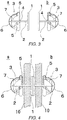
- FIG. 1 is a partially exploded side view showing a structure of a fastening tool (A-type) in accordance with an aspect of the present disclosure.
- the fastening tool is constituted by a pair of fastening members a and b.
- Each of these fastening members a and b is provided with a substrate 1 having a piercing needle 2 on its rear surface and a pierce catch 3 that holds the piercing needle 2.
- the pierce catch 3 is provided with a bottom surface member 5 having a through hole 4 for the piercing needle 2, a holding member 7 (catch member) that extends from the bottom surface member 5 and holds the tip portion of the piercing needle 2, and a casing 6 that houses the bottom surface member 5 and the holding member 7 inside thereof.
- the substrate 1 is preferably formed into a planar shape. This shape is used because when attached to a material cloth, the material cloth is held between the substrate and the snap pin 3. From this point of view, the surface of the pierce catch 3 on the substrate 1 side is also preferably formed into a planar shape.
- a female hook 9 forming a detachable section is formed on the surface of the substrate 1 of the fastening member a.
- a male hook 8 forming the detachable section is formed on the surface of the substrate 1 of the fastening member b.
- the pierce catch 3 in addition to the above-mentioned structure, those having known structures may also be used.
- FIG. 2 is an explanatory view showing a state in which the fastening tool as shown in FIG. 1 is attached to an opening portion of a handbag or the like.
- each of the piercing needles 2 formed on the substrates 1 of the fastening members a and b is kept in a state drawn from the pierce catch 3.
- the piercing needles 2 are made to penetrate opposed material cloths 10 at portions to be engaged with each other of the opening portions, and the tip of each of the piercing needles 2 is allowed to pass through the through hole 4 of the pierce catch 3 so that fastening members a and b are fixed onto the material cloths 10.
- the fastening members a and b are respectively attached the opposing surfaces of the material cloth 10 on the opening portion.
- the opening portion can be closed.
- the opening portion can be opened.
- the fitting forces of the male hook 8 and the female hook 9 are made different from each other.
- the force of the spring of the female hook 9 is great, upon removing the male hook 8 from the female hook 9, the pierce catch 3 undesirably comes off the piercing needle 2 before the male hook 8 has come off the female hook 9. That is, when the pierce catch 3 is pinched by fingers and pulled, the piercing needle 2 is drawn from the pierce catch 3 in the case when a force for removing the male hook 8 from the female hook 9 is greater than a force by which the piercing needle 2 is held by the pierce catch 3, with the result that the opening portion is not opened.
- the force required for detachably attaching the male hook 8 to the female hook 9 is designed to become smaller than the force by which the piercing needle 2 is held by the piece catch 3.
- the fastening tool As long as the material is cloth or leather, the corresponding attaching process can be carried out at any place without requiring any working process. Moreover, since the removing process can be freely carried out, the same material can be used many times. Furthermore, since the attaching process is carried out by the piercing needle, hardly any trace remains on the cloth.
- By attaching the fastening tool to an existing product simple cloth can be formed into a muffler, scarf, cloak, or the like with the fastening tool, which is fastened before the neck.
- a tote bag is designed to be openable and closable at any desired position to be closed. Furthermore, by using a plurality of fastening tools, a plurality of binding positions may be set.
- FIG. 3 is a partially exploded side view showing a fastening tool (B-type) in accordance with another aspect of the present disclosure.
- FIG. 4 is an explanatory view showing a using state of the fastening tool shown in FIG. 3 . Additionally, those components that are the same as those shown in FIGs 1 and 2 are indicated by the same reference numerals and the description thereof will be omitted.
- the fastening tool in accordance with the present aspect is characterized in that the substrate 1 of the fastening tool itself, shown in FIG. 3 , is formed by using a magnet.
- the substrates 1 By forming the substrate 1 itself by using a magnet in this manner, the substrates 1 can be easily detachably attached to each other. Additionally, one of the substrates 1 may be formed by a magnet, with the other being formed by a ferromagnetic material. Moreover, the above-mentioned magnet may be formed on the entire surface or one portion of the substrate 1 (the illustration of which is omitted).
- the thickness of the substrate 1 is preferably set to such a thickness as not to cause a space between the material cloths 10 and 10.
- the planar shape of the substrate 1 may be formed into various shapes, such as a round shape, a square shape, a rectangular shape, or the like.
- the number of the piercing needles 2 extended from the substrate 1 may be set to one or a plural number depending on the shape of the substrate 1. Additionally, in the case when a plurality of piercing needles 2 are used, it is supposed that a plurality of pierce catches corresponding to the respective piercing needles 2 are used.
- the fastening tool in the same manner as described above, as long as the material is cloth or leather, the corresponding attaching process can be carried out at any place without requiring any working process. Moreover, since the removing process can be freely carried out, the same material can be used many times. Furthermore, since the attaching process is carried out by the piercing needle, hardly any trace remains on the cloth.
- By attaching the fastening tool to an existing product simple cloth can be formed into a muffler, scarf, cloak, or the like with the fastening tool, which is fastened before the neck.
- a tote bag is designed to be openable and closable at any desired position to be closed.
- a plurality of binding positions may be set.
- the detachably attaching action is carried out by using a magnet, the opening and closing actions are easily carried out. By changing the force of the magnet, an optimal opening/closing force can be obtained in accordance with its use.
- FIG. 5 is a partially exploded side view showing a fastening tool (C-type) in accordance with another aspect of the present disclosure.
- This fastening tool has a structure in which one of the substrates 1 of the fastening tool of B-type shown in FIGs 3 and 4 is replaced from a magnet to a magnetic material.
- the present aspect is characterized in that a concave portion 11 is formed on one of detachably attaching surfaces of the substrate 1, with a convex portion 10 to be fitted to the concave portion 11 being formed on the other detachably attaching surface.
- FIG. 6 is an explanatory view showing a using state of the fastening tool shown in FIG. 5 .
- the fastening members a and b of the substrates 1 are attached to a material cloth 10 on the opening portion of clothing or the like by using a piercing needle 2 and a pierce catch 3 in the same sequence of processes as that of the fastening tools shown in FIGs 1 and 2 .
- the substrates 1 are respectively formed by the magnet and the magnetic material, they are positively attracted and fixed to each other by mutual attracting functions so that the opening portion can be closed.
- the convex portion 10 and the concave portion 11 of the substrates 1 are fitted to each other, the substrates 1 are mutually overlapped with each other correctly and attracted and fixed to each other, without deviations in the plane direction. Furthermore, since the substrates 1 are prevented from being mutually deviated in the plane direction in the attracted and fixed state, it is possible to prevent the opening portion from being opened when a force of displacement is exerted on the opening portion. Additionally, the shapes and numbers of the convex portion 10 and the concave portion 11 may be desirably determined depending on circumstances. Moreover, in the present aspect, the convex portion 10 and the concave portion 11 are formed on the center of the substrate 1; however, this structure is not limiting.
- the convex portion 10 and the concave portion 11 having a round doughnut shape may be formed, with the surfaces of the substrates 1 being firmly attracted and fixed to each other in the center.
- the convex portion 10 and the concave portion 11 with desired angles in the circumferential direction of the substrates 1, it becomes possible to prevent the substrates 1 from mutually rotating, and consequently to be firmly attached and fixed to each other (illustrations of any of modified examples are omitted).
- the fastening tool in the same manner as described above, as long as the material is cloth or leather, the corresponding attaching process can be carried out at any place without requiring any working process. Moreover, since the removing process can be freely carried out, the same material can be used many times. Furthermore, since the attaching process is carried out by the piercing needle, hardly any trace remains on the cloth.
- By attaching the fastening tool to an existing product simple cloth can be formed into a muffler, scarf, cloak, or the like with the fastening tool, which is fastened before the neck.
- a tote bag is designed to be openable and closable at any desired position to be closed.
- a plurality of binding positions may be set.
- the detachably attaching process is carried out by using a magnet, the opening/closing action can be easily carried out. By changing the force of the magnet, it is possible to obtain an optimal opening/closing force in accordance with the use.
- FIG. 7 is a partially exploded side view showing a fastening tool (B-type) in accordance with another aspect.
- This fastening tool is characterized in that its pierce catch has a ball catch structure that is different from the pierce catch 3 of FIGs 3 to 6 .
- the pierce catch 3 of this fastening tool is constituted by a casing 6 having an insertion opening 4 through which the piercing needle 2 is inserted and which is formed on the bottom surface member 5, a grip member 15 that is disposed on a ceiling portion of the casing 6 so as to penetrate it, and is pinched by fingers so as to be moved in the shaft direction and a tube-shaped member 18 that is secured onto the inside of the casing 6.
- the casing 6 is used for housing the inner structural members and for protecting them, and has such a shape as to make the appearance design beautiful.
- the grip member 15 has a through hole 14 in the center in the shaft direction so as to pass the piercing needle 2 therethrough.
- a washer-shaped pressing member 16 is formed on the end portion of the grip member 15.
- a flange is formed on the other end of the grip member 15 so as to be easily grabbed by fingers.
- a spring 20 is disposed between the pressing member 16 and the housing 6, and the pressing member 16 is pressed by the spring 20 in the direction toward the bottom surface member 5.
- the tube-shaped member 18 has a slanting wall 19 having a truncated cone shape the diameter of which is expanded toward the ceiling direction (right direction in the Figure) at the end portion thereof.
- the tube-shaped member 18 may be integrally formed with the casing 6. Between the slanting wall 19 and the pressing member 16, a plurality of ball members 17 are disposed so as to sandwich and hold the piercing needle 2. The number of the ball members 17 is set to two or more.
- FIG. 8 is an explanatory view showing the using state of the fastening tool shown in FIG. 7 .
- the flange of the end portion of the grip member 15 is held by fingers and pulled, the restricted state of the ball members 17 by the pressing member 16 and the slanting wall 19 is released.
- the piercing needle 2 is inserted from the insertion opening 4 of the casing 6, the piercing needle 2 is allowed to pass between the opposed ball members 17, and inserted into the through hole 14 of the grip member 15.
- the ball members 17 are pushed by the pressing member 16 by the action of the spring 20 so that the ball members 17 are successively pushed in the center direction along the slanting wall 19.
- the ball members 17 are pressed onto the piercing needle 2 so that the ball members 17 sandwich and hold the piercing needle 2.
- the piercing needle 2 is not drawn.
- the fastening tool of the present aspect allows the ball members 17 or the like to firmly sandwich and hold the piercing needle 2, it is possible to prevent the pierce catch 3 from coming off at the time of opening/closing the opening portion. Therefore, even in the case of a severe usage such as a tote bag or the like, the pierce catch 3 is prevented from coming off the material cloth. On the other hand, by pulling the grip member 15, the pierce catch 3 can be easily removed.
- the fastening tool in the same manner as described above, as long as the material is cloth or leather, the corresponding attaching process can be carried out at any place without requiring any working process. Moreover, since the removing process can be freely carried out, the same material can be used many times. Furthermore, since the attaching process is carried out by the piercing needle, hardly any trace remains on the cloth.
- By attaching the fastening tool to an existing product simple cloth can be formed into a muffler, scarf, cloak, or the like with the fastening tool, which is fastened before the neck.
- a tote bag can be designed to be openable and closable at any desired position to be closed.
- a plurality of binding positions may be set.
- the detachably attaching process is carried out by using a magnet, the opening/closing action can be easily carried out. By changing the force of the magnet, it is possible to obtain an optimal opening/closing force in accordance with the use.
- FIG. 9 is a partially exploded side view showing a fastening tool (D-type) in accordance with an embodiment of the present invention.
- FIG. 10 is an explanatory view showing the using state of the fastening tool shown in FIG. 9 .
- One of the fastening member a of the fastening tool has a structure in which a ring-shaped magnet 22 (first detachably attaching member) is formed near the center of the peripheral portion of the casing 6 in a vertical direction relative to the formation direction of the through hole 14 and the substrate 1 having a plate-like shape is formed, with the piercing needle 2 being extended from its center.
- the substrate 1 may be made of either a non-magnetic material or a magnetic material.
- the ring-shaped magnet 22 is formed into a doughnut shape and a required magnetic force is obtained depending on its diameter and thickness. Moreover, the ring-shaped magnet 22 may be coated with a cover (not shown). Furthermore, the shape in the vicinity of the center of the peripheral portion of the casing 6 may be designed so as to be expanded in a vertical direction relative to the through hole 14, with the above-mentioned members being installed therein (not shown). Additionally, as will be described later, since it is only necessary for the pierce catch 3 to be concealed by a doughnut-shaped member 21, it is only necessary to form the ring-shaped magnet 22 so as to have a size larger than the casing.
- the fastening member b has a structure in which the doughnut-shaped member 21 (second detachably attaching member) is formed on the surface of the plate-like substrate 1.
- the piercing needle 2 is extended from the center of the substrate 1.
- the piercing needle 2 is sandwiched and held by the pierce catch 3.
- the doughnut-shaped member 21 is molded into a tube-shape from a magnetic metal plate.
- the doughnut-shaped member 21 may have a solid structure or a hollow structure (not shown).
- the shape and area of the end face of the doughnut-shaped member 21 are desirably formed so as to have substantially the same shape and area as the ring-shaped magnet 22 from the functional point of view as well as from the appearance point of view.
- the doughnut-shaped member 21 may be integrally formed with the substrate 1. Furthermore, the length in the shaft direction (lateral direction, length direction of the piercing needle 2 in the Figure) of the doughnut-shaped member 21 is supposed to be greater than a length from the end face of the ring-shaped magnet 22 to the other end of the grip member 15. Thus, the casing 6 of the pierce catch 3 can be housed by the doughnut-shaped member 21.
- the shape of the doughnut-shaped member 21 may be freely set as long as it can house the casing 6 and is magnetically attracted by the ring-shaped magnet 22.
- the inside shape of the doughnut-shaped member 21 is preferably set to have substantially the same shape as the outer shape of the casing 6. As shown in FIG.
- the doughnut-shaped member 21 can be naturally covered on the casing 6 and finally attracted to be fixed by the ring-shaped magnet 22.
- the doughnut-shaped member 21 of the fastening member b is attracted and fixed onto the ring-shaped magnet 22 so as to allow the doughnut-shaped member 21 to cover the casing 6 of the fastening member a. Since the ring-shaped magnet 22 is installed on the outside of the casing 6, the casing 6 protrudes onto one direction side of the ring-shaped magnet 22, with the casing 6 being inserted inside of the doughnut-shaped member 21 in its attracted and fixed state.
- fastening members a and b are mutually attracted and fixed at a correct position, it is possible to prevent the opening portion from being undesirably opened, and also to prevent the doughnut-shaped member 21 and the ring-shaped magnet 22 in the attracted and fixed state from being deviated in the surface direction.
- the substrate 1 of one of the fastening members a is formed into a plate-like shape, it is possible to reduce the occurrence of such a problem in that it is undesirably caught by an object, a finger, or the like, in comparison with the case in which the pierce catch 3 protrudes outward. Furthermore, an accessory member 23, such as jewelry or the like, can be easily attached to the substrate 1. Additionally, in the present embodiment, the pierce catch 3, which is of the type shown in the FIGs 7 and 8 , has been used; however, any of the types shown in the FIGs 1 to 6 may be used. Moreover, the doughnut-shaped member 21 may be formed by using a magnet. Furthermore, when the doughnut-shaped member 21 is made of a magnet, the ring-shaped magnet 22 is made of a magnetic material.
- FIG. 11 is a partially exploded side view showing a pierce catch whose structure is modified from the structure of the pierce catches 3 relating to the fastening tools shown in FIGs 1 to 6 .
- FIG. 12 is a cross-sectional view showing a pierce catch whose structure is altered from the pierce catch relating to the fastening tools shown in FIGs 7 to 10 .
- a cylinder member 25 is formed on the lower portion of the bottom surface member 5, and a snap pin groove 21 is formed in the vicinity of the end portion of the peripheral wall.
- a stop ring 24 having a disc shape with an opening formed in the center is attached onto the cylinder member 25.
- a flange portion is formed on an outer wall intermediate surface of the casing 6 so as to be expanded sideward, and a cylinder portion 25 is formed on the lower portion thereof.
- a snap pin groove 21 is formed in the vicinity of the end portion of the cylinder portion 25.
- FIG. 13 is an explanatory view showing a state in which an accessory is attached to the fastening tool shown in FIG. 12 .
- an accessory 23 made of a flat plate having a flower shape is shown.
- the plate thickness of the accessory 23 is supposed to be smaller than the gap between the flange and the stop ring.
- the stop ring is drawn from the cylinder portion.
- the accessory 23 with an opening formed in the center is inserted.
- the cylinder portion is inserted to the opening formed in the center of the accessory 23.
- the stop ring 24 is attached to the cylinder portion, and the snap pin is fitted to the snap pin groove 21 so that the accessory 23 is fixed by the stop ring 26 and the flange.
- the accessory 23 may have any shape as long as it can be inserted to the cylinder member or the cylinder portion.
- the accessory 23 may be attached thereto in the same sequence of processes as those described above (not shown). First, by removing the snap pin 26, the stop ring 24 is drawn from the cylinder member 25, and the accessory 23 with an opening formed in the center is inserted thereto. Then, the cylinder member 25 is inserted into the opening formed in the center of this flower shape, and the stop ring 24 is attached to the cylinder member 25. Lastly, the snap pin 26 is fitted to the snap pin groove 21 so that the accessory 23 is fixed by the stop ring 26 and the bottom surface member.
- the accessory 23 can be easily attached to the pierce catch 3. Moreover, many accessories 23 may be attached thereto as long as they are provided with holes through which the cylinder member 25 can be inserted.
- FIG. 14 is a cross-sectional view showing a pierce catch in accordance with an embodiment of the present invention.
- This pierce catch is characterized in that the pierce catch of the fastening tool shown in FIGs 7 to 13 is provided with a cap 30 for use in preventing an erroneous operation.
- a screw is formed on the outer side face of the casing of the pierce catch.
- a thread corresponding to the screw of the casing is formed in the vicinity of the inside end portion of the cap 30, and the cap 30 can be attached to the casing in a manner so as to cover the grip member serving as the detachably attaching portion for the piercing needle 2.
- the entire shape of the cap 30 may be formed into a semispherical shape or a butterfly shape that can be easily grabbed. Thus, it is possible to prevent an accidental contact with the grip portion, with the result that the piercing needle is subsequently released. Additionally, since the cap 30 is formed to prevent the accidental contact with the grip portion, one portion thereof may be opened as long as it can surround the periphery of the grip member.
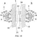
- FIG. 15 is a cross-sectional view showing a fastening tool in accordance with another aspect of the present disclosure.
- a convex portion 31 is formed on the surface of the substrate 1 of the fastening member a
- a concave portion 32 is formed on the surface of the substrate 1 of the fastening member b.
- the concave portion is constituted by a protruding portion formed on the substrate 1 and a doughnut-shaped magnet that is thicker than the protruding portion, and fitted to the periphery of the protruding portion.
- the convex portion 31 Upon attracting the substrates 1 to be fixed to each other, the convex portion 31 is fitted to the concave portion 32.
- the pierce catch 3 has the same structure as those shown in FIGs 7 to 14 ; however, those shown in FIGs 1 to 6 may also be used (not shown).
- FIG. 16 is a cross-sectional view showing a fastening tool in accordance with an embodiment of the present invention.
- FIG. 17 is an explanatory view showing the using state of the fastening tool shown in FIG. 16 .
- This fastening tool is constituted by a pair of fastening members a and b.
- Each of the fastening members a and b is provided with a substrate 1 with a piercing needle 2 formed on its rear surface and a pierce catch 3 that holds the piercing needle 2.
- This pierce catch 3 is the same as the pierce catch 3 shown in FIGs 7 and 8 ; therefore, the explanation thereof will be omitted, and the same components are indicated by the same reference numerals.
- a collar portion 6a is formed in the substantially center position of the peripheral portion in the axial direction (in the vertical direction in the Figure, in the length direction of the through hole 14) of casing 6 of the pierce catch 3.
- a ring member 51 is attached to the collar portion 6a on the fastening member b side. One portion of the end face of the ring member 51 is made in contact with the collar portion 6a.
- a snap pin groove 53 for holding the snap pin 52 is formed on the inner surface of the ring member 51.
- the snap pin 52 formed by bending and shaping a rod shaped metal into a C-letter shape, is fitted to the snap pin groove 53 when expanded.
- an inner collar portion 51a is formed toward the inside, and is made in contact with the collar portion 6a of the casing 6.
- the inner collar portion 51a is made in contact with the end surface of a tube-shaped member 60, which will be described later, of the fastening member b so as to regulate the position.
- the outer surface of the ring member 51 has a simple cylindrical curved surface in the Figure; however, it may be formed into a shape whose design performance is enhanced.
- a fixed plate 54 is formed on the ring member 51.
- the fixed plate 54 has a disc shape in which a hole 55 to which the casing 6 is fitted is formed in the center, with a shallow ring-shaped concave portion 56 for holding the collar portion 6a of the casing being further formed on the periphery of the hole 55.
- the end face of the fixed plate 54 is made in contact with the end face of the ring member 51, and joined thereto by bonding or welding.
- the collar portion 6a of the casing 6 is fitted to the ring-shaped concave portion 56, and sandwiched by an inner collar portion 51a of the ring member 51 so that the casing 6 is held and fixed by the ring member 51 and the fixed plate 54.
- the insertion opening 4 of the casing 6 is exposed from the fixed plate 54, and the grip member 15 is brought to an exposed state inside the ring member 51.
- the snap pin 52 is located in the vicinity of the ceiling of the casing 6.
- a tube-shaped member 60 is formed on the side opposite to the piercing needle 2.
- the tube-shaped member 60 may be integrally molded with the substrate 1.
- the length in the axial direction (vertical direction in the Figure, length direction of the piercing needle 2) of the tube-shaped member 60 and the diameter thereof are set to such levels as to sufficiently house the casing 6 of the fastening member a and the grip member 15.
- the outer diameter of the tube-shaped member 60 is slightly smaller than the inner diameter of the ring member 51.
- the thickness of the tube-shaped member 60 is set in such a range so as to be inserted to a gap between the inner surface of the ring member 51 of the fastening member a and the outer surface of the casing 6.
- a protruding portion 61 to be engaged with the snap pin 52 is formed on the periphery of the tube-shaped member 60.
- the protruding portion 61 has a semi-circular shape, and is designed to be smoothly made in contact with the snap pin 52 so as to easily push and expand the snap pin 52.
- the respective dimensions are determined so that in a state where the protruding portion 61 is engaged with the snap pin 52, the edge of the tube-shaped member 60 is made in contact with the inner collar portion 51a of the ring member 51.
- the fastening member a and the fastening member b are respectively attached to the opening portion of a handbag, or the like (not shown).
- the operations of the pierce catch 3 are the same as those of the pierce catch 3 shown in FIGs 7 and 8 .
- the tube-shaped member 60 of the fastening member b is inserted the inside of the ring member 51 of the fastening member a, and also pushed therein so as to cover the casing 6.
- the protruding portion 61 of the tube-shaped member 60 pushes the snap pin 52 to be expanded, and gets over this so that the end portion thereof is made in contact with the inner collar portion 51a. In this state, the tube-shaped member 60 is held inside the ring member 51 by the inner collar portion 51a and the snap pin 52.
- the casing 6 is inserted the inside of the tube-shaped member 60.
- the external appearance of the fastening tool is covered with the ring member 51 and the tube-shaped member 60, with the inner structure being concealed, so that it looks compact and is kept in a beautiful state.
- the compact external appearance has no catching portions; therefore, even when it protrudes inside a handbag or the like, no objects are caught therewith.
- the substrate 1 of one of the fastening member a into a plate-like shape, a problem in which an article, a finger or the like is caught by the fastening member hardly occurs in comparison with the case in which the pierce catch 3 protrudes outward. Moreover, an accessory member such as jewelry can be easily attached to the substrate 1. Additionally, in the present embodiment, the pierce catch 3, which is of the type shown in FIGs 7 and 8 , has been used; however, any of the types shown in FIGs 1 to 6 may be used.
- the fastening tool As long as the material is cloth or leather, the corresponding attaching process can be carried out at any place without requiring any big working process. Moreover, since the removing process can be freely carried out, the same material can be used many times. Furthermore, since the attaching process is carried out by the piercing needle, hardly any trace remains on the cloth.
- By attaching the fastening tool to an existing product simple cloth can be formed into a muffler, scarf, cloak, or the like, which is fastened before the neck. Since it is easily attached to any position, for example, a tote bag is designed to be openable and closable at any desired position to be closed. Furthermore, by using a plurality of fastening tools, a plurality of binding positions may be set.
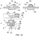
- FIG. 18 is a cross-sectional view showing a fastening tool in accordance with an aspect of the present disclosure.
- FIG. 19 and FIG. 29(a) are explanatory views showing a using state of the fastening tool shown in FIG. 18 .
- a concave portion 65 is formed on the surface of the fastening member a of the substrate 1
- a convex portion 66 is formed on the surface of the fastening member b of the substrate 1.
- a protruding portion 67 having a round shape when seen in a plan view is formed in the center.
- a doughnut-shaped magnet 68 that is thicker than the protruding portion 67 is formed.
- the substrate 1 and the magnet 68 are covered with a cover 69.
- the cover 69 which is made of a thin material, is formed from the periphery of the substrate 1 to the periphery of the magnet 68 as well as to the end face on the fastening member b side of the magnet 68, and is further formed diagonally from the inside end portion of the magnet 68 toward the inside thereof.
- the end portion of the cover 69 is connected to a corner of the protruding portion 67 of the substrate 1.
- the concave portion 65 can be formed in the vicinity of the center portion of the entire fastening member a.
- a hook member 70 is formed on a surface opposite to the surface on which the convex portion 66 of the fastening member b is formed, as shown in (a) of the Figure.
- the hook member 70 is a molded member made of metal, and one end 71 thereof is welded onto the substrate 1, and the center portion is separated from the surface of the substrate 1 to be curved outward, and again made in contact with the surface of the substrate 1, with the other end being formed into a warped shape.
- a wire of a safety pin P is inserted from the other end 72 of the warped shape so as to be inserted into the hook member 70.
- an insertion hole is formed in place of the hook member 70 is shown.
- the insertion hole 73 is formed by welding the two ends of a semi-tubed member 74 onto the substrate 1.
- the wire of the safety pin P is inserted into the insertion hole 73.
- this fastening tool allows the fastening member b to be engaged with on the safety pin P attached to one portion of a bag B or a muffler S.
- the safety pin P is attached to, for example, one portion of the opening portion of a handbag, and at this time, onto a wire PI protruding on the rear surface, the hook member 70 is pushed so that the fastening member b is locked.
- the fastening member a is fixed to the corresponding position.
- the concave portion 65 of the fastening member a is fitted to the convex portion 66 of the fastening member b so that the substrates 1 are mutually attracted and fixed to each other by the magnetic force of the magnet 68.
- the opening portion of the handbag is made openable and closable.
- the corresponding attaching process can be carried out at any place without requiring any big working process.
- the attaching process is carried out by using the safety pin P, its versatility is further increased.
- the removing process can be freely carried out, the same material can be used many times.
- the attaching process is carried out by the piercing needle 2 and safety pin P, hardly any trace remains on the cloth.
- a tote bag Since it is easily attached to any position, for example, a tote bag is designed to be openable and closable at any desired position to be closed. Furthermore, by using a plurality of fastening tools, a plurality of binding positions may be set. By using a safety pin with an accessory, it is possible to form an openable/closable fastening tool with the accessory.
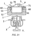
- FIG. 20 is a cross-sectional view showing a fastening tool in accordance with another aspect of the present disclosure.
- FIG. 21 and FIG. 29(b) are explanatory views showing a using state of the fastening tool shown in FIG. 20 .
- a ring member 80 is formed on the substrate 1.
- a snap pin groove 53 for holding a snap pin 52 is formed on the inner surface of the ring member 80.
- the snap pin 52 which is formed by bending and shaping a rod shaped metal into a C-letter shape, is fitted to the snap pin groove 53 when expanded.
- the outer surface of the ring member 80 has a simple cylindrical curved surface in the Figure; however, it may be formed into a shape whose design performance is enhanced.
- a tube-shaped member 60 is formed on the substrate 1 of the fastening member b.
- the tube-shaped member 60 may be integrally molded together with the substrate 1.
- the length in the axial direction (vertical direction in the Figure) of the tube-shaped member 60 is substantially the same as the length in the axial direction (vertical direction in the Figure) of the ring member 80.
- the outer diameter of the tube-shaped member 60 is slightly smaller than the inner diameter of the ring member 80.
- a protruding portion 61 to be engaged with the snap pin 52 is formed on the periphery of the tube-shaped member 60.
- the protruding portion 61 has a substantially semi-circular shape, and is designed to be smoothly made in contact with the snap pin 52 so as to easily push and expand the snap pin 52.
- the respective dimensions are determined so that in a state where the protruding portion 61 is engaged with the snap pin 52, the edge of the tube-shaped member 60 is made in contact with the surface of the substrate 1 of the fastening member a.
- the fastening member a when used, for example, is attached to the opening portion of a handbag B (not shown).
- the operations of the pierce catch 3 are the same as the pierce catch shown in FIGs 7 and 8 .
- the fastening member b is engaged with the safety pin P.
- the safety pin P is attached to the corresponding position of the opening portion of the handbag, and at this time, onto a wire PI protruding on the rear surface, the hook member 70 is pushed so that the fastening member b is locked.
- the tube-shaped member 60 of the fastening member b is pushed and inserted inside the ring member 80 of the fastening member a.
- the protruding portion 61 of the tube-shaped member 60 pushes the snap pin 52 to be expanded, and gets over this so that the end portion thereof is made in contact with the substrate 1.
- the tube-shaped member 60 is held inside the ring member 80 by the snap pin 52.
- the external appearance of the fastening tool looks compact and beautiful, with the ring member 80 and the tube-shaped member 60 being exactly fitted to each other. Furthermore, the compact external appearance has no catching portions; therefore, even when it protrudes inside a handbag or the like, no objects are caught therewith. Additionally, in the present aspect, the pierce catch 3, which is of the type shown in the FIGs 7 and 8 , has been used; however, pierce catches 3 of any of the types shown in FIGs 1 to 6 may be used.
- the fastening tool As long as the material is cloth or leather, the corresponding attaching process can be carried out at any place without requiring any big working process. Moreover, since the removing process can be freely carried out, the same material can be used many times. Furthermore, since the attaching process is carried out by the piercing needle 2 and the safety pin P, hardly any trace remains on the cloth.
- By attaching the fastening tool to an existing product simple cloth can be formed into a muffler, scarf, cloak, or the like, which is fastened before the neck. Since it is easily attached to any position, for example, a tote bag is designed to be openable and closable at any desired position to be closed. Furthermore, by using a plurality of fastening tools, a plurality of binding positions may be set. Furthermore, by using the safety pin with an accessory, it is possible to form an opening/closing fastening tool with the accessory.
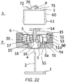
- FIG. 22 is a cross-sectional view showing a fastening tool in accordance with an embodiment of the present invention.
- FIG. 23 is an explanatory view showing a using state of the fastening tool shown in FIG. 22 .
- a tube-shaped member 60 may be formed on the peripheral edge of the substrate 1 of the fastening member b.
- the other components have the same structures as those of the fastening member b shown in FIGs 20 and 21 ; therefore, the same components are indicated by the same reference numerals.
- a protruding portion 61 to be engaged with the snap pin 52 is formed on the periphery of the tube-shaped member 60.
- fastening member a has the same structure as the fastening member b shown in FIGs 16 and 17 , the same components are indicated by the same reference numerals.
- the external appearance of the fastening tool looks compact and more beautiful, with the ring member and the tube-shaped member 60 being exactly fitted to each other. Moreover, no flange structures are formed on the substrate 1, and a compact external appearance with no catching portions is provided; therefore, even when it protrudes inside a handbag or the like, no objects are caught therewith. Additionally, in the present embodiment, the pierce catch 3, which is of the type shown in the FIGs 7 and 8 , has been used; however, pierce catches 3 of any of the types shown in FIGs 1 to 6 may be used.
- the fastening tool is configured such that without the necessity of any processing jobs, such as caulking, sewing and the like, of buttons, metal fittings, etc., on the opening portion of clothing, baggage or the like, after the piercing needle 2 has penetrated at a desired portion on the two sides of the opening portion, it can be fixed by using an attached pierce catch; therefore, a detachably attaching process can be easily carried out. Moreover, since the tip of the piercing needle 2 is enclosed by the pierce catch 3, it can be safely used without causing a stab wound or the like at the time of handling.
- any processing jobs such as caulking, sewing and the like, of buttons, metal fittings, etc.
- FIG. 24 is an explanatory view showing a using mode of the fastening tool shown in the above-mentioned aspects and embodiments.
- this fastening tool by fixing a wrapping cloth to double rings attached to the two sides of a handle, a handbag B is formed.
- fastening members a and b are attached to the opening portion of the handbag B.
- the attaching method is the same as shown in the above-mentioned aspects and embodiments.
- the opening portion is closed by fastening the fastening members a and b to each other.
- FIG. 25 is an explanatory view showing an example in which the fastening tool is applied to a tote bag.
- the fastening members a and b are attached to the opening portion of the tote bag T, and the opening portion is closed by fastening the fastening members a and b to each other.
- FIG. 26 is an explanatory view showing an example in which the fastening tool is applied to a muffler or stolen.
- the fastening members a and b are attached to each of two portions of the muffler S, and the fastening members a and b are fastened to each other, with the muffler S being wound around the neck.
- the muffler S can be easily fixed around the neck.
- the fastening members a and b are attached to each of the two portions of the stolen S, and the fastening members a and b are fastened to each other, with the stolen S being put over the head.
- the stolen S can be easily put over the head.
- FIG. 27 is an explanatory view showing an example in which only one of the fastening members is used.
- FIG. 28 is an explanatory view showing a using state of the fastening member shown in FIG. 27 .
- This fastening member a has a structure in which a magnet 1a is attached on the surface of the substrate 1.
- the fastening member a is attached to the opening portion of a handbag B or the like, by using the same method as described above.
- a clip 50 made of a magnetic material is held at a position opposed to the fastening member a.
- the clip 50 which is made of a magnetic material, is attracted by the magnet 1a of the fastening member and fixed thereon.
- An accessory 51 may be attached to one of the surfaces of the clip 50.
- the shape of the clip 50 is not limited by the one shown in FIG. 27 , as long as it has a surface that can be attracted by the magnet 1a.
Description
- This invention relates to a fastening tool using a piercing needle with a pierce catch, which is used for freely opening/closing the opening portion of clothing, baggage or the like.
- Conventionally, a handle as described in
JP 2008110196 A FIG. 25 ofJP 2008/110196 A -
US 2011/047759 A1 describes a closure which includes a first section having a bore, the bore having a crimped opening smaller than an inner portion thereof, and a second section having a shaft which is at least partially deformed inside the bore to lock the two sections together. The closure may be a magnetic snap fastener or mechanical snap fastener. The magnetic or mechanical snap components releasably connect a first and second sheet material. The first section of the closure may be an ornamental cap or button. -
US 2006/123606 A1 describes a device for joining sets of two or more clothing items which comprises at least two identical components that can be coupled to each other, as well as a textile item that incorporates the device for pairing the items. Each of the components is in turn divided into an outer part and an inner part that are also coupled to each other by inserting ribs provided on the inner face of the outer part in the orifice made in the centre of the inner part so that they are secured in them. - However, in the case when a handbag is formed by using the above-mentioned handle and wrapping cloth, its opening portion into and from which things are put and taken out is kept opened. On the other hand, in the case when normal metal fittings or fasteners are used, a problem is raised in that troublesome processes are required since processing jobs, such as caulking, sewing and the like, need to be carried out.
- The present invention is defined by the appended claims.
-
-
FIG. 1 is a cross-sectional view showing a structure of a fastening tool (A-type) in accordance with an aspect of the present disclosure; -
FIG. 2 is an explanatory view showing a state in which a fastening tool shown inFIG. 1 is attached to an opening portion of a handbag or the like; -
FIG. 3 is a partially exploded side view showing a fastening tool (B-type) in accordance with an aspect of the present disclosure; -
FIG. 4 is an explanatory view showing a using state of the fastening tool shown inFIG. 3 ; -
FIG. 5 is a partially exploded side view showing a fastening tool (C-type) in accordance with an aspect of the present disclosure; -
FIG. 6 is an explanatory view showing a using state of the fastening tool shown inFIG. 5 ; -
FIG. 7 is a partially exploded side view showing a fastening tool (B-type) in accordance with an aspect of the present disclosure; -
FIG. 8 is an explanatory view showing a using state of the fastening tool shown inFIG. 7 ; -
FIG. 9 is a partially exploded side view showing a fastening tool (D-type) in accordance with an embodiment of the present invention; -
FIG. 10 is an explanatory view showing a using state of the fastening tool shown inFIG. 9 ; -
FIG. 11 is a partially exploded side view showing a pierce catch in which the structure of apierce catch 3 shown inFIGs 1 to 6 is altered; -
FIG. 12 is a cross-sectional view showing a pierce catch in which the structure of the pierce catch shown inFIGs 7 to 10 is altered; -
FIG. 13 is an explanatory view showing a state in which an accessory is attached to a fastening tool shown inFIG. 12 ; -
FIG. 14 is a cross-sectional view showing a pierce catch in accordance with an embodiment of the present invention; -
FIG. 15 is a cross-sectional view showing a fastening tool in accordance with an aspect of the present disclosure; -
FIG. 16 is a cross-sectional view showing a fastening tool in accordance with an embodiment of the present invention; -
FIG. 17 is an explanatory view showing a using state of the fastening tool shown inFIG. 16 ; -
FIG. 18 is a cross-sectional view showing a fastening tool in accordance with an aspect of the present disclosure; -
FIG. 19 is an explanatory view showing a using state of the fastening tool shown inFIG. 18 ; -
FIG. 20 is a cross-sectional view showing a fastening tool in accordance with an aspect of the present disclosure; -
FIG. 21 is an explanatory view showing a using state of the fastening tool shown inFIG. 20 ; -
FIG. 22 is a cross-sectional view showing a fastening tool in accordance with an embodiment of the present invention; -
FIG. 23 is an explanatory view showing a using state of the fastening tool shown inFIG. 22 ; -
FIG. 24 is an explanatory view showing using modes of fastening tools shown in the above-mentioned aspects and embodiments; -
FIG. 25 is an explanatory view showing an example in which a fastening tool is applied to a tote bag; -
FIG. 26 is an explanatory view showing an example in which a fastening tool is applied to a muffler or a stole; -
FIG. 27 is an explanatory view showing an example in which only one fastening member of a fastening tool is used; -
FIG. 28 is an explanatory view showing a using state of the fastening member shown inFIG. 27 ; and -
FIG. 29 is an explanatory view showing a using method of the some of the above-mentioned aspects, examples and embodiments. - Referring to attached drawings, the following description will explain aspects of the present disclosure and embodiments of the present invention based upon respective separated types of a fastening member of a fastening tool. Additionally, in the respective aspects and embodiments, with respect to the types, the explanation will be given to types A, B, C and D; however, the fastening tool of the present invention is not intended to be limited by these.
-
FIG. 1 is a partially exploded side view showing a structure of a fastening tool (A-type) in accordance with an aspect of the present disclosure. The fastening tool is constituted by a pair of fastening members a and b. Each of these fastening members a and b is provided with asubstrate 1 having apiercing needle 2 on its rear surface and apierce catch 3 that holds thepiercing needle 2. Thepierce catch 3 is provided with abottom surface member 5 having a throughhole 4 for thepiercing needle 2, a holding member 7 (catch member) that extends from thebottom surface member 5 and holds the tip portion of thepiercing needle 2, and acasing 6 that houses thebottom surface member 5 and theholding member 7 inside thereof. Thesubstrate 1 is preferably formed into a planar shape. This shape is used because when attached to a material cloth, the material cloth is held between the substrate and thesnap pin 3. From this point of view, the surface of thepierce catch 3 on thesubstrate 1 side is also preferably formed into a planar shape. - Moreover, on the surface of the
substrate 1 of the fastening member a, afemale hook 9 forming a detachable section is formed. On the surface of thesubstrate 1 of the fastening member b, amale hook 8 forming the detachable section is formed. As the pierce catch 3, in addition to the above-mentioned structure, those having known structures may also be used. -
FIG. 2 is an explanatory view showing a state in which the fastening tool as shown inFIG. 1 is attached to an opening portion of a handbag or the like. First, each of thepiercing needles 2 formed on thesubstrates 1 of the fastening members a and b is kept in a state drawn from thepierce catch 3. Next, thepiercing needles 2 are made to penetrateopposed material cloths 10 at portions to be engaged with each other of the opening portions, and the tip of each of thepiercing needles 2 is allowed to pass through the throughhole 4 of thepierce catch 3 so that fastening members a and b are fixed onto thematerial cloths 10. The fastening members a and b are respectively attached the opposing surfaces of thematerial cloth 10 on the opening portion. Then, by fitting themale hook 8 and thefemale hook 9 of the opposing fastening members a and b on the opening portion to each other, the opening portion can be closed. By pulling themale hook 8 and thefemale hook 9 to be separated from each other, the opening portion can be opened. - By adjusting the force of the spring of the
female hook 9, the fitting forces of themale hook 8 and thefemale hook 9 are made different from each other. In the case when the force of the spring of thefemale hook 9 is great, upon removing themale hook 8 from thefemale hook 9, thepierce catch 3 undesirably comes off the piercingneedle 2 before themale hook 8 has come off thefemale hook 9. That is, when thepierce catch 3 is pinched by fingers and pulled, the piercingneedle 2 is drawn from thepierce catch 3 in the case when a force for removing themale hook 8 from thefemale hook 9 is greater than a force by which the piercingneedle 2 is held by thepierce catch 3, with the result that the opening portion is not opened. For this reason, in the present disclosure, with respect to the force of the spring of thefemale hook 9, the force required for detachably attaching themale hook 8 to thefemale hook 9 is designed to become smaller than the force by which the piercingneedle 2 is held by thepiece catch 3. - In accordance with this fastening tool, as long as the material is cloth or leather, the corresponding attaching process can be carried out at any place without requiring any working process. Moreover, since the removing process can be freely carried out, the same material can be used many times. Furthermore, since the attaching process is carried out by the piercing needle, hardly any trace remains on the cloth. By attaching the fastening tool to an existing product, simple cloth can be formed into a muffler, scarf, cloak, or the like with the fastening tool, which is fastened before the neck. Moreover, since it is easily attached to any position, for example, a tote bag is designed to be openable and closable at any desired position to be closed. Furthermore, by using a plurality of fastening tools, a plurality of binding positions may be set.
-
FIG. 3 is a partially exploded side view showing a fastening tool (B-type) in accordance with another aspect of the present disclosure.FIG. 4 is an explanatory view showing a using state of the fastening tool shown inFIG. 3 . Additionally, those components that are the same as those shown inFIGs 1 and 2 are indicated by the same reference numerals and the description thereof will be omitted. The fastening tool in accordance with the present aspect is characterized in that thesubstrate 1 of the fastening tool itself, shown inFIG. 3 , is formed by using a magnet. - By forming the
substrate 1 itself by using a magnet in this manner, thesubstrates 1 can be easily detachably attached to each other. Additionally, one of thesubstrates 1 may be formed by a magnet, with the other being formed by a ferromagnetic material. Moreover, the above-mentioned magnet may be formed on the entire surface or one portion of the substrate 1 (the illustration of which is omitted). - In the case when the fastening tool of the present invention is attached to a
material cloth 10 and used, the thickness of thesubstrate 1 is preferably set to such a thickness as not to cause a space between thematerial cloths substrate 1 may be formed into various shapes, such as a round shape, a square shape, a rectangular shape, or the like. Furthermore, the number of the piercingneedles 2 extended from thesubstrate 1 may be set to one or a plural number depending on the shape of thesubstrate 1. Additionally, in the case when a plurality of piercingneedles 2 are used, it is supposed that a plurality of pierce catches corresponding to the respective piercingneedles 2 are used. - In accordance with this fastening tool, in the same manner as described above, as long as the material is cloth or leather, the corresponding attaching process can be carried out at any place without requiring any working process. Moreover, since the removing process can be freely carried out, the same material can be used many times. Furthermore, since the attaching process is carried out by the piercing needle, hardly any trace remains on the cloth. By attaching the fastening tool to an existing product, simple cloth can be formed into a muffler, scarf, cloak, or the like with the fastening tool, which is fastened before the neck. Moreover, since it is easily attached to any position, for example, a tote bag is designed to be openable and closable at any desired position to be closed. Furthermore, by using a plurality of fastening tools, a plurality of binding positions may be set. In particular, since the detachably attaching action is carried out by using a magnet, the opening and closing actions are easily carried out. By changing the force of the magnet, an optimal opening/closing force can be obtained in accordance with its use.
-
FIG. 5 is a partially exploded side view showing a fastening tool (C-type) in accordance with another aspect of the present disclosure. This fastening tool has a structure in which one of thesubstrates 1 of the fastening tool of B-type shown inFIGs 3 and 4 is replaced from a magnet to a magnetic material. Moreover, the present aspect is characterized in that aconcave portion 11 is formed on one of detachably attaching surfaces of thesubstrate 1, with aconvex portion 10 to be fitted to theconcave portion 11 being formed on the other detachably attaching surface. -
FIG. 6 is an explanatory view showing a using state of the fastening tool shown inFIG. 5 . In this fastening tool, the fastening members a and b of thesubstrates 1 are attached to amaterial cloth 10 on the opening portion of clothing or the like by using a piercingneedle 2 and apierce catch 3 in the same sequence of processes as that of the fastening tools shown inFIGs 1 and 2 . Since thesubstrates 1 are respectively formed by the magnet and the magnetic material, they are positively attracted and fixed to each other by mutual attracting functions so that the opening portion can be closed. - Moreover, since the
convex portion 10 and theconcave portion 11 of thesubstrates 1 are fitted to each other, thesubstrates 1 are mutually overlapped with each other correctly and attracted and fixed to each other, without deviations in the plane direction. Furthermore, since thesubstrates 1 are prevented from being mutually deviated in the plane direction in the attracted and fixed state, it is possible to prevent the opening portion from being opened when a force of displacement is exerted on the opening portion. Additionally, the shapes and numbers of theconvex portion 10 and theconcave portion 11 may be desirably determined depending on circumstances. Moreover, in the present aspect, theconvex portion 10 and theconcave portion 11 are formed on the center of thesubstrate 1; however, this structure is not limiting. For example, theconvex portion 10 and theconcave portion 11 having a round doughnut shape may be formed, with the surfaces of thesubstrates 1 being firmly attracted and fixed to each other in the center. Moreover, by forming theconvex portion 10 and theconcave portion 11 with desired angles in the circumferential direction of thesubstrates 1, it becomes possible to prevent thesubstrates 1 from mutually rotating, and consequently to be firmly attached and fixed to each other (illustrations of any of modified examples are omitted). - In accordance with this fastening tool, in the same manner as described above, as long as the material is cloth or leather, the corresponding attaching process can be carried out at any place without requiring any working process. Moreover, since the removing process can be freely carried out, the same material can be used many times. Furthermore, since the attaching process is carried out by the piercing needle, hardly any trace remains on the cloth. By attaching the fastening tool to an existing product, simple cloth can be formed into a muffler, scarf, cloak, or the like with the fastening tool, which is fastened before the neck. Moreover, since it is easily attached to any position, for example, a tote bag is designed to be openable and closable at any desired position to be closed. Furthermore, by using a plurality of fastening tools, a plurality of binding positions may be set. In particular, since the detachably attaching process is carried out by using a magnet, the opening/closing action can be easily carried out. By changing the force of the magnet, it is possible to obtain an optimal opening/closing force in accordance with the use.
-
FIG. 7 is a partially exploded side view showing a fastening tool (B-type) in accordance with another aspect. This fastening tool is characterized in that its pierce catch has a ball catch structure that is different from thepierce catch 3 ofFIGs 3 to 6 . - The
pierce catch 3 of this fastening tool is constituted by acasing 6 having aninsertion opening 4 through which the piercingneedle 2 is inserted and which is formed on thebottom surface member 5, agrip member 15 that is disposed on a ceiling portion of thecasing 6 so as to penetrate it, and is pinched by fingers so as to be moved in the shaft direction and a tube-shapedmember 18 that is secured onto the inside of thecasing 6. Thecasing 6 is used for housing the inner structural members and for protecting them, and has such a shape as to make the appearance design beautiful. Thegrip member 15 has a throughhole 14 in the center in the shaft direction so as to pass the piercingneedle 2 therethrough. Moreover, a washer-shaped pressingmember 16 is formed on the end portion of thegrip member 15. A flange is formed on the other end of thegrip member 15 so as to be easily grabbed by fingers. Aspring 20 is disposed between the pressingmember 16 and thehousing 6, and the pressingmember 16 is pressed by thespring 20 in the direction toward thebottom surface member 5. The tube-shapedmember 18 has a slantingwall 19 having a truncated cone shape the diameter of which is expanded toward the ceiling direction (right direction in the Figure) at the end portion thereof. - The tube-shaped
member 18 may be integrally formed with thecasing 6. Between the slantingwall 19 and the pressingmember 16, a plurality ofball members 17 are disposed so as to sandwich and hold the piercingneedle 2. The number of theball members 17 is set to two or more. -
FIG. 8 is an explanatory view showing the using state of the fastening tool shown inFIG. 7 . When the flange of the end portion of thegrip member 15 is held by fingers and pulled, the restricted state of theball members 17 by the pressingmember 16 and the slantingwall 19 is released. In this state, when the piercingneedle 2 is inserted from theinsertion opening 4 of thecasing 6, the piercingneedle 2 is allowed to pass between theopposed ball members 17, and inserted into the throughhole 14 of thegrip member 15. - Next, when the
grip member 15 is released from the hand, theball members 17 are pushed by the pressingmember 16 by the action of thespring 20 so that theball members 17 are successively pushed in the center direction along the slantingwall 19. Thus, theball members 17 are pressed onto the piercingneedle 2 so that theball members 17 sandwich and hold the piercingneedle 2. Even upon trying to draw the piercingneedle 2 in this state, since theball members 17 are pushed by the slantingwall 19 in such a direction as to further sandwich the piercingneedle 2, the piercingneedle 2 is not drawn. - On the other hand, in the case when the piercing
needle 2 is drawn, the flange of thegrip member 15 is pinched by fingers and pulled, the sandwiched state of the piercingneedle 2 by theball members 17 is released so that the piercingneedle 2 can be easily drawn out. - As described above, since the fastening tool of the present aspect allows the
ball members 17 or the like to firmly sandwich and hold the piercingneedle 2, it is possible to prevent thepierce catch 3 from coming off at the time of opening/closing the opening portion. Therefore, even in the case of a severe usage such as a tote bag or the like, thepierce catch 3 is prevented from coming off the material cloth. On the other hand, by pulling thegrip member 15, thepierce catch 3 can be easily removed. - Moreover, in accordance with the fastening tool, in the same manner as described above, as long as the material is cloth or leather, the corresponding attaching process can be carried out at any place without requiring any working process. Moreover, since the removing process can be freely carried out, the same material can be used many times. Furthermore, since the attaching process is carried out by the piercing needle, hardly any trace remains on the cloth. By attaching the fastening tool to an existing product, simple cloth can be formed into a muffler, scarf, cloak, or the like with the fastening tool, which is fastened before the neck. Moreover, since it is easily attached to any position, for example, a tote bag can be designed to be openable and closable at any desired position to be closed. Furthermore, by using a plurality of fastening tools, a plurality of binding positions may be set. In particular, since the detachably attaching process is carried out by using a magnet, the opening/closing action can be easily carried out. By changing the force of the magnet, it is possible to obtain an optimal opening/closing force in accordance with the use.
-
FIG. 9 is a partially exploded side view showing a fastening tool (D-type) in accordance with an embodiment of the present invention.FIG. 10 is an explanatory view showing the using state of the fastening tool shown inFIG. 9 . One of the fastening member a of the fastening tool has a structure in which a ring-shaped magnet 22 (first detachably attaching member) is formed near the center of the peripheral portion of thecasing 6 in a vertical direction relative to the formation direction of the throughhole 14 and thesubstrate 1 having a plate-like shape is formed, with the piercingneedle 2 being extended from its center. Thesubstrate 1 may be made of either a non-magnetic material or a magnetic material. The ring-shapedmagnet 22 is formed into a doughnut shape and a required magnetic force is obtained depending on its diameter and thickness. Moreover, the ring-shapedmagnet 22 may be coated with a cover (not shown). Furthermore, the shape in the vicinity of the center of the peripheral portion of thecasing 6 may be designed so as to be expanded in a vertical direction relative to the throughhole 14, with the above-mentioned members being installed therein (not shown). Additionally, as will be described later, since it is only necessary for thepierce catch 3 to be concealed by a doughnut-shapedmember 21, it is only necessary to form the ring-shapedmagnet 22 so as to have a size larger than the casing. - Since the inner structure of the
pierce catch 3 is the same as that of thepierce catch 3 shownFIGs 7 and 8 , the same components are indicated by the same reference numerals and the description thereof will be omitted. - On the other hand, the fastening member b has a structure in which the doughnut-shaped member 21 (second detachably attaching member) is formed on the surface of the plate-
like substrate 1. The piercingneedle 2 is extended from the center of thesubstrate 1. The piercingneedle 2 is sandwiched and held by thepierce catch 3. The doughnut-shapedmember 21 is molded into a tube-shape from a magnetic metal plate. The doughnut-shapedmember 21 may have a solid structure or a hollow structure (not shown). Moreover, the shape and area of the end face of the doughnut-shapedmember 21 are desirably formed so as to have substantially the same shape and area as the ring-shapedmagnet 22 from the functional point of view as well as from the appearance point of view. The doughnut-shapedmember 21 may be integrally formed with thesubstrate 1. Furthermore, the length in the shaft direction (lateral direction, length direction of the piercingneedle 2 in the Figure) of the doughnut-shapedmember 21 is supposed to be greater than a length from the end face of the ring-shapedmagnet 22 to the other end of thegrip member 15. Thus, thecasing 6 of thepierce catch 3 can be housed by the doughnut-shapedmember 21. In this case, the shape of the doughnut-shapedmember 21 may be freely set as long as it can house thecasing 6 and is magnetically attracted by the ring-shapedmagnet 22. The inside shape of the doughnut-shapedmember 21 is preferably set to have substantially the same shape as the outer shape of thecasing 6. As shown inFIG. 10 , since thecasing 6 is inserted inside of the doughnut-shapedmember 21 without a gap, and since an R portion is formed on each of the end portions of thecasing 6, the doughnut-shapedmember 21 can be naturally covered on thecasing 6 and finally attracted to be fixed by the ring-shapedmagnet 22. - The following description will discuss the using state of the fastening tool. The doughnut-shaped
member 21 of the fastening member b is attracted and fixed onto the ring-shapedmagnet 22 so as to allow the doughnut-shapedmember 21 to cover thecasing 6 of the fastening member a. Since the ring-shapedmagnet 22 is installed on the outside of thecasing 6, thecasing 6 protrudes onto one direction side of the ring-shapedmagnet 22, with thecasing 6 being inserted inside of the doughnut-shapedmember 21 in its attracted and fixed state. Thus, since the fastening members a and b are mutually attracted and fixed at a correct position, it is possible to prevent the opening portion from being undesirably opened, and also to prevent the doughnut-shapedmember 21 and the ring-shapedmagnet 22 in the attracted and fixed state from being deviated in the surface direction. - Moreover, since the
substrate 1 of one of the fastening members a is formed into a plate-like shape, it is possible to reduce the occurrence of such a problem in that it is undesirably caught by an object, a finger, or the like, in comparison with the case in which thepierce catch 3 protrudes outward. Furthermore, anaccessory member 23, such as jewelry or the like, can be easily attached to thesubstrate 1. Additionally, in the present embodiment, thepierce catch 3, which is of the type shown in theFIGs 7 and 8 , has been used; however, any of the types shown in theFIGs 1 to 6 may be used. Moreover, the doughnut-shapedmember 21 may be formed by using a magnet. Furthermore, when the doughnut-shapedmember 21 is made of a magnet, the ring-shapedmagnet 22 is made of a magnetic material. -
FIG. 11 is a partially exploded side view showing a pierce catch whose structure is modified from the structure of the pierce catches 3 relating to the fastening tools shown inFIGs 1 to 6 .FIG. 12 is a cross-sectional view showing a pierce catch whose structure is altered from the pierce catch relating to the fastening tools shown inFIGs 7 to 10 . - In the
pierce catch 3 shown inFIG. 11 , acylinder member 25 is formed on the lower portion of thebottom surface member 5, and asnap pin groove 21 is formed in the vicinity of the end portion of the peripheral wall. Astop ring 24 having a disc shape with an opening formed in the center is attached onto thecylinder member 25. Asnap pin 26, formed by bending and shaping a rod-shaped metal into a C-letter shape, is fitted to thesnap pin groove 21 when expanded. By thissnap pin 26, thestop ring 24 is prevented from coming off thecylinder member 25. Between thestop ring 24 and thecasing 6, a gap for use in holding anaccessory member 23 in a fitted state therein is formed. - In the
pierce catch 3 shown inFIG. 12 , a flange portion is formed on an outer wall intermediate surface of thecasing 6 so as to be expanded sideward, and acylinder portion 25 is formed on the lower portion thereof. Asnap pin groove 21 is formed in the vicinity of the end portion of thecylinder portion 25. Asnap pin 26, formed by bending and shaping a rod-shaped metal into a C-letter shape, is fitted to thesnap pin groove 21 when expanded. By thissnap pin 26, thestop ring 24 is prevented from coming off the cylinder portion. Between thestop ring 24 and the flange portion, a gap for use in holding anaccessory member 23 in a fitted state therein is formed. -
FIG. 13 is an explanatory view showing a state in which an accessory is attached to the fastening tool shown inFIG. 12 . In an example of this Figure, anaccessory 23 made of a flat plate having a flower shape is shown. The plate thickness of theaccessory 23 is supposed to be smaller than the gap between the flange and the stop ring. By removing thesnap pin 26, the stop ring is drawn from the cylinder portion. Then, theaccessory 23 with an opening formed in the center is inserted. The cylinder portion is inserted to the opening formed in the center of theaccessory 23. Moreover, thestop ring 24 is attached to the cylinder portion, and the snap pin is fitted to thesnap pin groove 21 so that theaccessory 23 is fixed by thestop ring 26 and the flange. Additionally, theaccessory 23 may have any shape as long as it can be inserted to the cylinder member or the cylinder portion. - Additionally, in the fastening tool shown in
FIG. 11 also, theaccessory 23 may be attached thereto in the same sequence of processes as those described above (not shown). First, by removing thesnap pin 26, thestop ring 24 is drawn from thecylinder member 25, and the accessory 23 with an opening formed in the center is inserted thereto. Then, thecylinder member 25 is inserted into the opening formed in the center of this flower shape, and thestop ring 24 is attached to thecylinder member 25. Lastly, thesnap pin 26 is fitted to thesnap pin groove 21 so that theaccessory 23 is fixed by thestop ring 26 and the bottom surface member. - In accordance with this structure, the
accessory 23 can be easily attached to thepierce catch 3. Moreover,many accessories 23 may be attached thereto as long as they are provided with holes through which thecylinder member 25 can be inserted. -
FIG. 14 is a cross-sectional view showing a pierce catch in accordance with an embodiment of the present invention. This pierce catch is characterized in that the pierce catch of the fastening tool shown inFIGs 7 to 13 is provided with acap 30 for use in preventing an erroneous operation. A screw is formed on the outer side face of the casing of the pierce catch. A thread corresponding to the screw of the casing is formed in the vicinity of the inside end portion of thecap 30, and thecap 30 can be attached to the casing in a manner so as to cover the grip member serving as the detachably attaching portion for the piercingneedle 2. The entire shape of thecap 30 may be formed into a semispherical shape or a butterfly shape that can be easily grabbed. Thus, it is possible to prevent an accidental contact with the grip portion, with the result that the piercing needle is subsequently released. Additionally, since thecap 30 is formed to prevent the accidental contact with the grip portion, one portion thereof may be opened as long as it can surround the periphery of the grip member. -
FIG. 15 is a cross-sectional view showing a fastening tool in accordance with another aspect of the present disclosure. In this fastening tool, aconvex portion 31 is formed on the surface of thesubstrate 1 of the fastening member a, and aconcave portion 32 is formed on the surface of thesubstrate 1 of the fastening member b. The concave portion is constituted by a protruding portion formed on thesubstrate 1 and a doughnut-shaped magnet that is thicker than the protruding portion, and fitted to the periphery of the protruding portion. Upon attracting thesubstrates 1 to be fixed to each other, theconvex portion 31 is fitted to theconcave portion 32. Additionally, thepierce catch 3 has the same structure as those shown inFIGs 7 to 14 ; however, those shown inFIGs 1 to 6 may also be used (not shown). -
FIG. 16 is a cross-sectional view showing a fastening tool in accordance with an embodiment of the present invention.FIG. 17 is an explanatory view showing the using state of the fastening tool shown inFIG. 16 . This fastening tool is constituted by a pair of fastening members a and b. Each of the fastening members a and b is provided with asubstrate 1 with a piercingneedle 2 formed on its rear surface and apierce catch 3 that holds the piercingneedle 2. Thispierce catch 3 is the same as thepierce catch 3 shown inFIGs 7 and 8 ; therefore, the explanation thereof will be omitted, and the same components are indicated by the same reference numerals. - In the fastening member a, a
collar portion 6a is formed in the substantially center position of the peripheral portion in the axial direction (in the vertical direction in the Figure, in the length direction of the through hole 14) ofcasing 6 of thepierce catch 3. Aring member 51 is attached to thecollar portion 6a on the fastening member b side. One portion of the end face of thering member 51 is made in contact with thecollar portion 6a. Asnap pin groove 53 for holding thesnap pin 52 is formed on the inner surface of thering member 51. Thesnap pin 52, formed by bending and shaping a rod shaped metal into a C-letter shape, is fitted to thesnap pin groove 53 when expanded. On thecolor portion 6a side of thering member 51, aninner collar portion 51a is formed toward the inside, and is made in contact with thecollar portion 6a of thecasing 6. Theinner collar portion 51a is made in contact with the end surface of a tube-shapedmember 60, which will be described later, of the fastening member b so as to regulate the position. - The outer surface of the
ring member 51 has a simple cylindrical curved surface in the Figure; however, it may be formed into a shape whose design performance is enhanced. Moreover, a fixedplate 54 is formed on thering member 51. The fixedplate 54 has a disc shape in which ahole 55 to which thecasing 6 is fitted is formed in the center, with a shallow ring-shapedconcave portion 56 for holding thecollar portion 6a of the casing being further formed on the periphery of thehole 55. Furthermore, the end face of the fixedplate 54 is made in contact with the end face of thering member 51, and joined thereto by bonding or welding. By attaching the fixedplate 54 to thering member 51, thecollar portion 6a of thecasing 6 is fitted to the ring-shapedconcave portion 56, and sandwiched by aninner collar portion 51a of thering member 51 so that thecasing 6 is held and fixed by thering member 51 and the fixedplate 54. In this state, theinsertion opening 4 of thecasing 6 is exposed from the fixedplate 54, and thegrip member 15 is brought to an exposed state inside thering member 51. Thesnap pin 52 is located in the vicinity of the ceiling of thecasing 6. - On the other hand, on the
substrate 1 of the fastening member b, a tube-shapedmember 60 is formed on the side opposite to the piercingneedle 2. The tube-shapedmember 60 may be integrally molded with thesubstrate 1. In this case, the length in the axial direction (vertical direction in the Figure, length direction of the piercing needle 2) of the tube-shapedmember 60 and the diameter thereof are set to such levels as to sufficiently house thecasing 6 of the fastening member a and thegrip member 15. Moreover, the outer diameter of the tube-shapedmember 60 is slightly smaller than the inner diameter of thering member 51. Furthermore, the thickness of the tube-shapedmember 60 is set in such a range so as to be inserted to a gap between the inner surface of thering member 51 of the fastening member a and the outer surface of thecasing 6. On the periphery of the tube-shapedmember 60, a protrudingportion 61 to be engaged with thesnap pin 52 is formed. The protrudingportion 61 has a semi-circular shape, and is designed to be smoothly made in contact with thesnap pin 52 so as to easily push and expand thesnap pin 52. The respective dimensions are determined so that in a state where the protrudingportion 61 is engaged with thesnap pin 52, the edge of the tube-shapedmember 60 is made in contact with theinner collar portion 51a of thering member 51. - As shown in
FIG. 17 , when used, the fastening member a and the fastening member b are respectively attached to the opening portion of a handbag, or the like (not shown). The operations of thepierce catch 3 are the same as those of thepierce catch 3 shown inFIGs 7 and 8 . Upon closing the opening portion by the fastening members a and b, the tube-shapedmember 60 of the fastening member b is inserted the inside of thering member 51 of the fastening member a, and also pushed therein so as to cover thecasing 6. The protrudingportion 61 of the tube-shapedmember 60 pushes thesnap pin 52 to be expanded, and gets over this so that the end portion thereof is made in contact with theinner collar portion 51a. In this state, the tube-shapedmember 60 is held inside thering member 51 by theinner collar portion 51a and thesnap pin 52. - Moreover, the
casing 6 is inserted the inside of the tube-shapedmember 60. Thus, the external appearance of the fastening tool is covered with thering member 51 and the tube-shapedmember 60, with the inner structure being concealed, so that it looks compact and is kept in a beautiful state. Furthermore, the compact external appearance has no catching portions; therefore, even when it protrudes inside a handbag or the like, no objects are caught therewith. - In this case, by forming the
substrate 1 of one of the fastening member a into a plate-like shape, a problem in which an article, a finger or the like is caught by the fastening member hardly occurs in comparison with the case in which thepierce catch 3 protrudes outward. Moreover, an accessory member such as jewelry can be easily attached to thesubstrate 1. Additionally, in the present embodiment, thepierce catch 3, which is of the type shown inFIGs 7 and 8 , has been used; however, any of the types shown inFIGs 1 to 6 may be used. - In accordance with this fastening tool, as long as the material is cloth or leather, the corresponding attaching process can be carried out at any place without requiring any big working process. Moreover, since the removing process can be freely carried out, the same material can be used many times. Furthermore, since the attaching process is carried out by the piercing needle, hardly any trace remains on the cloth. By attaching the fastening tool to an existing product, simple cloth can be formed into a muffler, scarf, cloak, or the like, which is fastened before the neck. Since it is easily attached to any position, for example, a tote bag is designed to be openable and closable at any desired position to be closed. Furthermore, by using a plurality of fastening tools, a plurality of binding positions may be set.
-
FIG. 18 is a cross-sectional view showing a fastening tool in accordance with an aspect of the present disclosure.FIG. 19 andFIG. 29(a) are explanatory views showing a using state of the fastening tool shown inFIG. 18 . In this fastening tool, aconcave portion 65 is formed on the surface of the fastening member a of thesubstrate 1, and aconvex portion 66 is formed on the surface of the fastening member b of thesubstrate 1. - On the
substrate 1 of the fastening member a, a protrudingportion 67 having a round shape when seen in a plan view is formed in the center. On the periphery of this, a doughnut-shapedmagnet 68 that is thicker than the protrudingportion 67 is formed. Thesubstrate 1 and themagnet 68 are covered with acover 69. Thecover 69, which is made of a thin material, is formed from the periphery of thesubstrate 1 to the periphery of themagnet 68 as well as to the end face on the fastening member b side of themagnet 68, and is further formed diagonally from the inside end portion of themagnet 68 toward the inside thereof. The end portion of thecover 69 is connected to a corner of the protrudingportion 67 of thesubstrate 1. Thus, theconcave portion 65 can be formed in the vicinity of the center portion of the entire fastening member a. - On a surface opposite to the surface on which the
convex portion 66 of the fastening member b is formed, as shown in (a) of the Figure, ahook member 70 is formed. Thehook member 70 is a molded member made of metal, and oneend 71 thereof is welded onto thesubstrate 1, and the center portion is separated from the surface of thesubstrate 1 to be curved outward, and again made in contact with the surface of thesubstrate 1, with the other end being formed into a warped shape. Thus, a wire of a safety pin P is inserted from theother end 72 of the warped shape so as to be inserted into thehook member 70. In (b) of the Figure, an example in which an insertion hole is formed in place of thehook member 70 is shown. Theinsertion hole 73 is formed by welding the two ends of asemi-tubed member 74 onto thesubstrate 1. The wire of the safety pin P is inserted into theinsertion hole 73. - As shown in
FIG. 29(a) , this fastening tool allows the fastening member b to be engaged with on the safety pin P attached to one portion of a bag B or a muffler S. The safety pin P is attached to, for example, one portion of the opening portion of a handbag, and at this time, onto a wire PI protruding on the rear surface, thehook member 70 is pushed so that the fastening member b is locked. By piercing the piercingneedle 2 at a position corresponding to the one portion of the handbag, with thepierce catch 3 being attached thereto from the rear surface, the fastening member a is fixed to the corresponding position. Successively, theconcave portion 65 of the fastening member a is fitted to theconvex portion 66 of the fastening member b so that thesubstrates 1 are mutually attracted and fixed to each other by the magnetic force of themagnet 68. Thus, the opening portion of the handbag is made openable and closable. - In accordance with this fastening tool, as long as the material is cloth or leather, the corresponding attaching process can be carried out at any place without requiring any big working process. In particular, since the attaching process is carried out by using the safety pin P, its versatility is further increased. Moreover, since the removing process can be freely carried out, the same material can be used many times. Furthermore, since the attaching process is carried out by the piercing
needle 2 and safety pin P, hardly any trace remains on the cloth. By attaching the fastening tool to an existing product, simple cloth can be formed into a muffler, scarf, cloak, or the like, which is fastened before the neck. Since it is easily attached to any position, for example, a tote bag is designed to be openable and closable at any desired position to be closed. Furthermore, by using a plurality of fastening tools, a plurality of binding positions may be set. By using a safety pin with an accessory, it is possible to form an openable/closable fastening tool with the accessory. -
FIG. 20 is a cross-sectional view showing a fastening tool in accordance with another aspect of the present disclosure.FIG. 21 andFIG. 29(b) are explanatory views showing a using state of the fastening tool shown inFIG. 20 . In the fastening member a of this fastening tool, aring member 80 is formed on thesubstrate 1. On the inner surface of thering member 80, asnap pin groove 53 for holding asnap pin 52 is formed. Thesnap pin 52, which is formed by bending and shaping a rod shaped metal into a C-letter shape, is fitted to thesnap pin groove 53 when expanded. The outer surface of thering member 80 has a simple cylindrical curved surface in the Figure; however, it may be formed into a shape whose design performance is enhanced. - On the other hand, on the
substrate 1 of the fastening member b, a tube-shapedmember 60 is formed. The tube-shapedmember 60 may be integrally molded together with thesubstrate 1. In this case, the length in the axial direction (vertical direction in the Figure) of the tube-shapedmember 60 is substantially the same as the length in the axial direction (vertical direction in the Figure) of thering member 80. Moreover, the outer diameter of the tube-shapedmember 60 is slightly smaller than the inner diameter of thering member 80. On the periphery of the tube-shapedmember 60, a protrudingportion 61 to be engaged with thesnap pin 52 is formed. The protrudingportion 61 has a substantially semi-circular shape, and is designed to be smoothly made in contact with thesnap pin 52 so as to easily push and expand thesnap pin 52. The respective dimensions are determined so that in a state where the protrudingportion 61 is engaged with thesnap pin 52, the edge of the tube-shapedmember 60 is made in contact with the surface of thesubstrate 1 of the fastening member a. - As shown in
FIG. 21 andFIG. 29(b) , when used, for example, the fastening member a is attached to the opening portion of a handbag B (not shown). The operations of thepierce catch 3 are the same as the pierce catch shown inFIGs 7 and 8 . Moreover, the fastening member b is engaged with the safety pin P. The safety pin P is attached to the corresponding position of the opening portion of the handbag, and at this time, onto a wire PI protruding on the rear surface, thehook member 70 is pushed so that the fastening member b is locked. When the opening portion is closed by the fastening members a and b, the tube-shapedmember 60 of the fastening member b is pushed and inserted inside thering member 80 of the fastening member a. The protrudingportion 61 of the tube-shapedmember 60 pushes thesnap pin 52 to be expanded, and gets over this so that the end portion thereof is made in contact with thesubstrate 1. In this state, the tube-shapedmember 60 is held inside thering member 80 by thesnap pin 52. - As shown in
FIG. 21 , the external appearance of the fastening tool looks compact and beautiful, with thering member 80 and the tube-shapedmember 60 being exactly fitted to each other. Furthermore, the compact external appearance has no catching portions; therefore, even when it protrudes inside a handbag or the like, no objects are caught therewith. Additionally, in the present aspect, thepierce catch 3, which is of the type shown in theFIGs 7 and 8 , has been used; however, piercecatches 3 of any of the types shown inFIGs 1 to 6 may be used. - In accordance with this fastening tool, as long as the material is cloth or leather, the corresponding attaching process can be carried out at any place without requiring any big working process. Moreover, since the removing process can be freely carried out, the same material can be used many times. Furthermore, since the attaching process is carried out by the piercing
needle 2 and the safety pin P, hardly any trace remains on the cloth. By attaching the fastening tool to an existing product, simple cloth can be formed into a muffler, scarf, cloak, or the like, which is fastened before the neck. Since it is easily attached to any position, for example, a tote bag is designed to be openable and closable at any desired position to be closed. Furthermore, by using a plurality of fastening tools, a plurality of binding positions may be set. Furthermore, by using the safety pin with an accessory, it is possible to form an opening/closing fastening tool with the accessory. -
FIG. 22 is a cross-sectional view showing a fastening tool in accordance with an embodiment of the present invention.FIG. 23 is an explanatory view showing a using state of the fastening tool shown inFIG. 22 . As shown in the Figure, a tube-shapedmember 60 may be formed on the peripheral edge of thesubstrate 1 of the fastening member b. The other components have the same structures as those of the fastening member b shown inFIGs 20 and21 ; therefore, the same components are indicated by the same reference numerals. Moreover, on the periphery of the tube-shapedmember 60, a protrudingportion 61 to be engaged with thesnap pin 52 is formed. - Since the fastening member a has the same structure as the fastening member b shown in
FIGs 16 and17 , the same components are indicated by the same reference numerals. - As shown in
FIG. 23 , the external appearance of the fastening tool looks compact and more beautiful, with the ring member and the tube-shapedmember 60 being exactly fitted to each other. Moreover, no flange structures are formed on thesubstrate 1, and a compact external appearance with no catching portions is provided; therefore, even when it protrudes inside a handbag or the like, no objects are caught therewith. Additionally, in the present embodiment, thepierce catch 3, which is of the type shown in theFIGs 7 and 8 , has been used; however, piercecatches 3 of any of the types shown inFIGs 1 to 6 may be used. - As indicated by the aforementioned aspects and embodiments, the fastening tool is configured such that without the necessity of any processing jobs, such as caulking, sewing and the like, of buttons, metal fittings, etc., on the opening portion of clothing, baggage or the like, after the piercing
needle 2 has penetrated at a desired portion on the two sides of the opening portion, it can be fixed by using an attached pierce catch; therefore, a detachably attaching process can be easily carried out. Moreover, since the tip of the piercingneedle 2 is enclosed by thepierce catch 3, it can be safely used without causing a stab wound or the like at the time of handling. Furthermore, it is freely detachably attached and portable; therefore, in the case when a wrapping cloth or the like in hand is folded to be used as a make-shift bag, it is used as a fastening tool for locking the opening portion so that this fastening tool has a high quick response property. This property is exerted in the same manner in the case of the safety-pin P type. -
FIG. 24 is an explanatory view showing a using mode of the fastening tool shown in the above-mentioned aspects and embodiments. In this fastening tool, by fixing a wrapping cloth to double rings attached to the two sides of a handle, a handbag B is formed. As shown inFIG. 24(a) , fastening members a and b are attached to the opening portion of the handbag B. The attaching method is the same as shown in the above-mentioned aspects and embodiments. Next, as shown inFIG. 24(b) , the opening portion is closed by fastening the fastening members a and b to each other. -
FIG. 25 is an explanatory view showing an example in which the fastening tool is applied to a tote bag. In the same manner, the fastening members a and b are attached to the opening portion of the tote bag T, and the opening portion is closed by fastening the fastening members a and b to each other. -
FIG. 26 is an explanatory view showing an example in which the fastening tool is applied to a muffler or stole. For example, as shown inFIG. 26(a) , the fastening members a and b are attached to each of two portions of the muffler S, and the fastening members a and b are fastened to each other, with the muffler S being wound around the neck. Thus, the muffler S can be easily fixed around the neck. Moreover, as shown inFIG. 26(b) , the fastening members a and b are attached to each of the two portions of the stole S, and the fastening members a and b are fastened to each other, with the stole S being put over the head. Thus, the stole S can be easily put over the head. -
FIG. 27 is an explanatory view showing an example in which only one of the fastening members is used.FIG. 28 is an explanatory view showing a using state of the fastening member shown inFIG. 27 . This fastening member a has a structure in which amagnet 1a is attached on the surface of thesubstrate 1. The fastening member a is attached to the opening portion of a handbag B or the like, by using the same method as described above. Moreover, aclip 50 made of a magnetic material is held at a position opposed to the fastening member a. Theclip 50, which is made of a magnetic material, is attracted by themagnet 1a of the fastening member and fixed thereon. An accessory 51 may be attached to one of the surfaces of theclip 50. Additionally, the shape of theclip 50 is not limited by the one shown inFIG. 27 , as long as it has a surface that can be attracted by themagnet 1a. -
- 1...
- substrate
- 2...
- piercing needle
- 3...
- pierce catch
- 4...
- through hole
- 5...
- bottom surface member
- 6...
- casing
- 7...
- holding member
Claims (3)
- A fastening tool comprising:a pair of substrates (1) on which piercing needles (2) for penetrating a surface material, such as a material cloth or the like (10), are formed;pierce catches (3) that are formed so as to correspond to the paired substrates (1), and sandwich the piercing needle (2); characterized bydetachable means that includes a first detachable member formed on the outer periphery of the pierce catch (3) corresponding to one of the substrates (1), a second detachable member having such a shape as to surround the pierce catch (3), which is formed on the other substrate (1); whereinthe first detachable member and the second detachable member are configured by a combination of mutual magnets or a magnet and a magnetic member; orthe detachable means is configured by a male hook formed on one of the first detachable member and the second detachable member and a female hook formed on the other detachable member.
- The fastening tool according to claim 1, further comprising:
detachable means for accessories (23) is formed on the pierce catch (3) or the substrate (1). - The fastening tool according to claim 1, wherein a cap (30) for covering at least a detachably attaching operation portion of the piercing needle (2) is formed on the pierce catch (3).
Applications Claiming Priority (2)
| Application Number | Priority Date | Filing Date | Title |
|---|---|---|---|
| JP2013259159 | 2013-12-16 | ||
| PCT/JP2014/083300 WO2015093492A1 (en) | 2013-12-16 | 2014-12-16 | Fastener |
Publications (3)
| Publication Number | Publication Date |
|---|---|
| EP3085264A1 EP3085264A1 (en) | 2016-10-26 |
| EP3085264A4 EP3085264A4 (en) | 2017-09-27 |
| EP3085264B1 true EP3085264B1 (en) | 2019-07-31 |
Family
ID=53402837
Family Applications (1)
| Application Number | Title | Priority Date | Filing Date |
|---|---|---|---|
| EP14872822.3A Active EP3085264B1 (en) | 2013-12-16 | 2014-12-16 | Fastener |
Country Status (6)
| Country | Link |
|---|---|
| US (1) | US9795193B2 (en) |
| EP (1) | EP3085264B1 (en) |
| JP (3) | JP6101887B2 (en) |
| KR (1) | KR101830491B1 (en) |
| CN (1) | CN105358004B (en) |
| WO (1) | WO2015093492A1 (en) |
Families Citing this family (10)
| Publication number | Priority date | Publication date | Assignee | Title |
|---|---|---|---|---|
| US9618193B1 (en) * | 2016-05-12 | 2017-04-11 | Jeremy William Lord | Garment docking device for attaching personal devices |
| US10512292B2 (en) * | 2016-09-08 | 2019-12-24 | Tina Curtis | Accessory fastener device and method |
| WO2019006515A1 (en) * | 2017-07-07 | 2019-01-10 | Zavargê Pty Ltd | Improvements in bedding including push-pin securing assembly |
| CN109289133B (en) * | 2017-07-24 | 2021-10-08 | 霍尼韦尔国际公司 | Unitary strap construction for a mask |
| US10849393B2 (en) * | 2017-08-28 | 2020-12-01 | Gabrielle Rae Shapiro | Earring backing, earrings and earring display devices |
| US10918176B1 (en) * | 2019-10-08 | 2021-02-16 | Michael Roth | Magnetic backing for collector pin |
| WO2022145461A1 (en) * | 2020-12-28 | 2022-07-07 | 株式会社ワイズグレース | Pin fastener and personal accessory using same |
| USD1021685S1 (en) * | 2021-10-28 | 2024-04-09 | Chin-Sung Huang | Positioning pin of a seat belt buckle |
| US20230380553A1 (en) * | 2022-05-26 | 2023-11-30 | Aubrey Singleton | Magnetic pin attachment device |
| KR102585165B1 (en) * | 2023-04-03 | 2023-10-05 | 두영이노베이션 주식회사 | Holder assembly for personal items |
Family Cites Families (21)
| Publication number | Priority date | Publication date | Assignee | Title |
|---|---|---|---|---|
| US1336692A (en) * | 1919-11-03 | 1920-04-13 | Forman Joseph | Garment-fastener |
| US1438889A (en) * | 1921-01-15 | 1922-12-12 | Bates Edith May | Pin-attached snap fastener |
| JPS5929912U (en) * | 1982-08-20 | 1984-02-24 | 武田 精 | Rivet body for snap fastener |
| JPS63243312A (en) * | 1987-03-27 | 1988-10-11 | 株式会社 エルプラニングシステム | Method for mounting hook button and hook button |
| JPS6440008A (en) * | 1987-08-06 | 1989-02-10 | Tamao Morita | Clasp |
| JP2576220B2 (en) * | 1989-02-27 | 1997-01-29 | 日立プラント建設株式会社 | Flexible tube support device |
| JP2576220Y2 (en) * | 1992-07-21 | 1998-07-09 | 株式会社徳力本店 | Jewelry locking device |
| JP3046971B2 (en) * | 1992-11-30 | 2000-05-29 | ワイケイケイ株式会社 | Female body of snap button and crimping type |
| CN1065735C (en) * | 1994-02-28 | 2001-05-16 | 株式会社应用技术研究所 | Magnetic closure device |
| WO2000044257A1 (en) * | 1999-01-27 | 2000-08-03 | M & K Yokoya Co., Ltd. | Locking hardware |
| AU6540300A (en) * | 1999-06-16 | 2001-01-02 | Bonnie Roche | Display devices, accessories therefor and methods |
| JP3070576U (en) * | 2000-01-28 | 2000-08-04 | 良夫 松原 | Button with fastening function |
| JP2002065317A (en) * | 2000-09-01 | 2002-03-05 | Kiyohara Kk | Snap button |
| ES2237336B1 (en) * | 2004-12-14 | 2006-06-01 | Industrias Sinteticas Catalanas, S.L. | GARMENT UNION DEVICE AND TEXTILE ARTICLE THAT INCLUDES SUCH DEVICE. |
| US7356882B1 (en) * | 2005-11-22 | 2008-04-15 | Guadagno Iv James V | Magnetic flower attachment device |
| US20080005873A1 (en) * | 2006-07-06 | 2008-01-10 | Helen Of Troy Limited | Magnetic pushpin |
| JP4235978B2 (en) | 2006-10-04 | 2009-03-11 | 有限会社ウオーク社 | Handle |
| CN201375102Y (en) * | 2009-04-02 | 2010-01-06 | 东莞达基钮扣制品有限公司 | Fastener |
| US8052365B2 (en) * | 2009-04-15 | 2011-11-08 | Enlisted Design, LLC | Magnetic safety pushpin |
| US20110047759A1 (en) * | 2009-08-25 | 2011-03-03 | Romag Fasteners Inc. | Closures with magnetic and mechanical snap fastening and method of making the same |
| CN102415655A (en) * | 2011-11-24 | 2012-04-18 | 罗日梅 | Sewing-free pressing button |
-
2014
- 2014-12-16 US US14/902,321 patent/US9795193B2/en active Active
- 2014-12-16 EP EP14872822.3A patent/EP3085264B1/en active Active
- 2014-12-16 WO PCT/JP2014/083300 patent/WO2015093492A1/en active Application Filing
- 2014-12-16 JP JP2015553559A patent/JP6101887B2/en active Active
- 2014-12-16 KR KR1020157036508A patent/KR101830491B1/en active IP Right Grant
- 2014-12-16 CN CN201480038056.4A patent/CN105358004B/en not_active Expired - Fee Related
-
2016
- 2016-08-24 JP JP2016163810A patent/JP2016193343A/en active Pending
- 2016-08-24 JP JP2016163809A patent/JP6578480B2/en active Active
Non-Patent Citations (1)
| Title |
|---|
| None * |
Also Published As
| Publication number | Publication date |
|---|---|
| EP3085264A1 (en) | 2016-10-26 |
| EP3085264A4 (en) | 2017-09-27 |
| JP6101887B2 (en) | 2017-03-29 |
| WO2015093492A1 (en) | 2015-06-25 |
| KR20160013989A (en) | 2016-02-05 |
| KR101830491B1 (en) | 2018-02-20 |
| CN105358004A (en) | 2016-02-24 |
| JP6578480B2 (en) | 2019-09-25 |
| US20160374438A1 (en) | 2016-12-29 |
| JP2017018612A (en) | 2017-01-26 |
| CN105358004B (en) | 2018-10-19 |
| US9795193B2 (en) | 2017-10-24 |
| JPWO2015093492A1 (en) | 2017-03-16 |
| JP2016193343A (en) | 2016-11-17 |
Similar Documents
| Publication | Publication Date | Title |
|---|---|---|
| EP3085264B1 (en) | Fastener | |
| EP2351498B1 (en) | Magnetic lock catch | |
| US8667650B1 (en) | Decorative magnetic cufflink conversion device | |
| US20060236509A1 (en) | Magnetically Clasping Clothing Fastener for Presenting an Adornment | |
| EP2737816A1 (en) | Pressure snap fastener with a bivalent closure | |
| WO2016109249A1 (en) | Interchangeable button system technology | |
| US10064441B1 (en) | Locking button system | |
| US8578573B2 (en) | Pin fastener | |
| US9861167B2 (en) | Ornament holder | |
| KR102368301B1 (en) | Accessory clamps, assembly sets of ornamental clamps and ornaments | |
| US9489873B2 (en) | Textile fastener with cover | |
| JP2016049344A (en) | Snap fastener | |
| JP3196484U (en) | Fastener | |
| JP3196993U (en) | Fastener | |
| JP3211560U (en) | Fastener | |
| JP3216018U (en) | Fastener | |
| KR101729290B1 (en) | A female button for snap button | |
| KR101937618B1 (en) | A Fastener for Zipper | |
| KR101729292B1 (en) | A female button for snap button | |
| KR200487741Y1 (en) | Ornament | |
| KR101886009B1 (en) | A Fastener for Zipper | |
| KR101729291B1 (en) | A female button for snap button | |
| KR200476998Y1 (en) | Snap Button | |
| KR200346148Y1 (en) | snap type button | |
| JPS6214804A (en) | Cuff button |
Legal Events
| Date | Code | Title | Description |
|---|---|---|---|
| PUAI | Public reference made under article 153(3) epc to a published international application that has entered the european phase |
Free format text: ORIGINAL CODE: 0009012 |
|
| 17P | Request for examination filed |
Effective date: 20160718 |
|
| AK | Designated contracting states |
Kind code of ref document: A1 Designated state(s): AL AT BE BG CH CY CZ DE DK EE ES FI FR GB GR HR HU IE IS IT LI LT LU LV MC MK MT NL NO PL PT RO RS SE SI SK SM TR |
|
| AX | Request for extension of the european patent |
Extension state: BA ME |
|
| DAX | Request for extension of the european patent (deleted) | ||
| RIC1 | Information provided on ipc code assigned before grant |
Ipc: A44B 1/18 20060101ALI20170428BHEP Ipc: A44B 99/00 20100101AFI20170428BHEP Ipc: A44B 17/00 20060101ALI20170428BHEP Ipc: A44B 1/32 20060101ALI20170428BHEP |
|
| A4 | Supplementary search report drawn up and despatched |
Effective date: 20170830 |
|
| RIC1 | Information provided on ipc code assigned before grant |
Ipc: A44B 1/32 20060101ALI20170824BHEP Ipc: A44B 99/00 20100101AFI20170824BHEP Ipc: A44B 17/00 20060101ALI20170824BHEP Ipc: A44B 1/18 20060101ALI20170824BHEP |
|
| STAA | Information on the status of an ep patent application or granted ep patent |
Free format text: STATUS: EXAMINATION IS IN PROGRESS |
|
| 17Q | First examination report despatched |
Effective date: 20180425 |
|
| GRAP | Despatch of communication of intention to grant a patent |
Free format text: ORIGINAL CODE: EPIDOSNIGR1 |
|
| STAA | Information on the status of an ep patent application or granted ep patent |
Free format text: STATUS: GRANT OF PATENT IS INTENDED |
|
| INTG | Intention to grant announced |
Effective date: 20190205 |
|
| GRAS | Grant fee paid |
Free format text: ORIGINAL CODE: EPIDOSNIGR3 |
|
| GRAA | (expected) grant |
Free format text: ORIGINAL CODE: 0009210 |
|
| STAA | Information on the status of an ep patent application or granted ep patent |
Free format text: STATUS: THE PATENT HAS BEEN GRANTED |
|
| AK | Designated contracting states |
Kind code of ref document: B1 Designated state(s): AL AT BE BG CH CY CZ DE DK EE ES FI FR GB GR HR HU IE IS IT LI LT LU LV MC MK MT NL NO PL PT RO RS SE SI SK SM TR |
|
| REG | Reference to a national code |
Ref country code: CH Ref legal event code: EP Ref country code: GB Ref legal event code: FG4D |
|
| REG | Reference to a national code |
Ref country code: AT Ref legal event code: REF Ref document number: 1159985 Country of ref document: AT Kind code of ref document: T Effective date: 20190815 |
|
| REG | Reference to a national code |
Ref country code: IE Ref legal event code: FG4D |
|
| REG | Reference to a national code |
Ref country code: DE Ref legal event code: R096 Ref document number: 602014051058 Country of ref document: DE |
|
| REG | Reference to a national code |
Ref country code: NL Ref legal event code: MP Effective date: 20190731 |
|
| REG | Reference to a national code |
Ref country code: LT Ref legal event code: MG4D |
|
| REG | Reference to a national code |
Ref country code: AT Ref legal event code: MK05 Ref document number: 1159985 Country of ref document: AT Kind code of ref document: T Effective date: 20190731 |
|
| PG25 | Lapsed in a contracting state [announced via postgrant information from national office to epo] |
Ref country code: NO Free format text: LAPSE BECAUSE OF FAILURE TO SUBMIT A TRANSLATION OF THE DESCRIPTION OR TO PAY THE FEE WITHIN THE PRESCRIBED TIME-LIMIT Effective date: 20191031 Ref country code: SE Free format text: LAPSE BECAUSE OF FAILURE TO SUBMIT A TRANSLATION OF THE DESCRIPTION OR TO PAY THE FEE WITHIN THE PRESCRIBED TIME-LIMIT Effective date: 20190731 Ref country code: AT Free format text: LAPSE BECAUSE OF FAILURE TO SUBMIT A TRANSLATION OF THE DESCRIPTION OR TO PAY THE FEE WITHIN THE PRESCRIBED TIME-LIMIT Effective date: 20190731 Ref country code: HR Free format text: LAPSE BECAUSE OF FAILURE TO SUBMIT A TRANSLATION OF THE DESCRIPTION OR TO PAY THE FEE WITHIN THE PRESCRIBED TIME-LIMIT Effective date: 20190731 Ref country code: FI Free format text: LAPSE BECAUSE OF FAILURE TO SUBMIT A TRANSLATION OF THE DESCRIPTION OR TO PAY THE FEE WITHIN THE PRESCRIBED TIME-LIMIT Effective date: 20190731 Ref country code: PT Free format text: LAPSE BECAUSE OF FAILURE TO SUBMIT A TRANSLATION OF THE DESCRIPTION OR TO PAY THE FEE WITHIN THE PRESCRIBED TIME-LIMIT Effective date: 20191202 Ref country code: LT Free format text: LAPSE BECAUSE OF FAILURE TO SUBMIT A TRANSLATION OF THE DESCRIPTION OR TO PAY THE FEE WITHIN THE PRESCRIBED TIME-LIMIT Effective date: 20190731 Ref country code: NL Free format text: LAPSE BECAUSE OF FAILURE TO SUBMIT A TRANSLATION OF THE DESCRIPTION OR TO PAY THE FEE WITHIN THE PRESCRIBED TIME-LIMIT Effective date: 20190731 Ref country code: BG Free format text: LAPSE BECAUSE OF FAILURE TO SUBMIT A TRANSLATION OF THE DESCRIPTION OR TO PAY THE FEE WITHIN THE PRESCRIBED TIME-LIMIT Effective date: 20191031 |
|
| PG25 | Lapsed in a contracting state [announced via postgrant information from national office to epo] |
Ref country code: GR Free format text: LAPSE BECAUSE OF FAILURE TO SUBMIT A TRANSLATION OF THE DESCRIPTION OR TO PAY THE FEE WITHIN THE PRESCRIBED TIME-LIMIT Effective date: 20191101 Ref country code: AL Free format text: LAPSE BECAUSE OF FAILURE TO SUBMIT A TRANSLATION OF THE DESCRIPTION OR TO PAY THE FEE WITHIN THE PRESCRIBED TIME-LIMIT Effective date: 20190731 Ref country code: ES Free format text: LAPSE BECAUSE OF FAILURE TO SUBMIT A TRANSLATION OF THE DESCRIPTION OR TO PAY THE FEE WITHIN THE PRESCRIBED TIME-LIMIT Effective date: 20190731 Ref country code: LV Free format text: LAPSE BECAUSE OF FAILURE TO SUBMIT A TRANSLATION OF THE DESCRIPTION OR TO PAY THE FEE WITHIN THE PRESCRIBED TIME-LIMIT Effective date: 20190731 Ref country code: IS Free format text: LAPSE BECAUSE OF FAILURE TO SUBMIT A TRANSLATION OF THE DESCRIPTION OR TO PAY THE FEE WITHIN THE PRESCRIBED TIME-LIMIT Effective date: 20191130 Ref country code: RS Free format text: LAPSE BECAUSE OF FAILURE TO SUBMIT A TRANSLATION OF THE DESCRIPTION OR TO PAY THE FEE WITHIN THE PRESCRIBED TIME-LIMIT Effective date: 20190731 |
|
| PG25 | Lapsed in a contracting state [announced via postgrant information from national office to epo] |
Ref country code: TR Free format text: LAPSE BECAUSE OF FAILURE TO SUBMIT A TRANSLATION OF THE DESCRIPTION OR TO PAY THE FEE WITHIN THE PRESCRIBED TIME-LIMIT Effective date: 20190731 |
|
| PG25 | Lapsed in a contracting state [announced via postgrant information from national office to epo] |
Ref country code: PL Free format text: LAPSE BECAUSE OF FAILURE TO SUBMIT A TRANSLATION OF THE DESCRIPTION OR TO PAY THE FEE WITHIN THE PRESCRIBED TIME-LIMIT Effective date: 20190731 Ref country code: RO Free format text: LAPSE BECAUSE OF FAILURE TO SUBMIT A TRANSLATION OF THE DESCRIPTION OR TO PAY THE FEE WITHIN THE PRESCRIBED TIME-LIMIT Effective date: 20190731 Ref country code: DK Free format text: LAPSE BECAUSE OF FAILURE TO SUBMIT A TRANSLATION OF THE DESCRIPTION OR TO PAY THE FEE WITHIN THE PRESCRIBED TIME-LIMIT Effective date: 20190731 Ref country code: EE Free format text: LAPSE BECAUSE OF FAILURE TO SUBMIT A TRANSLATION OF THE DESCRIPTION OR TO PAY THE FEE WITHIN THE PRESCRIBED TIME-LIMIT Effective date: 20190731 |
|
| PG25 | Lapsed in a contracting state [announced via postgrant information from national office to epo] |
Ref country code: IS Free format text: LAPSE BECAUSE OF FAILURE TO SUBMIT A TRANSLATION OF THE DESCRIPTION OR TO PAY THE FEE WITHIN THE PRESCRIBED TIME-LIMIT Effective date: 20200224 Ref country code: SM Free format text: LAPSE BECAUSE OF FAILURE TO SUBMIT A TRANSLATION OF THE DESCRIPTION OR TO PAY THE FEE WITHIN THE PRESCRIBED TIME-LIMIT Effective date: 20190731 Ref country code: SK Free format text: LAPSE BECAUSE OF FAILURE TO SUBMIT A TRANSLATION OF THE DESCRIPTION OR TO PAY THE FEE WITHIN THE PRESCRIBED TIME-LIMIT Effective date: 20190731 Ref country code: CZ Free format text: LAPSE BECAUSE OF FAILURE TO SUBMIT A TRANSLATION OF THE DESCRIPTION OR TO PAY THE FEE WITHIN THE PRESCRIBED TIME-LIMIT Effective date: 20190731 |
|
| REG | Reference to a national code |
Ref country code: DE Ref legal event code: R097 Ref document number: 602014051058 Country of ref document: DE |
|
| PLBE | No opposition filed within time limit |
Free format text: ORIGINAL CODE: 0009261 |
|
| STAA | Information on the status of an ep patent application or granted ep patent |
Free format text: STATUS: NO OPPOSITION FILED WITHIN TIME LIMIT |
|
| PG2D | Information on lapse in contracting state deleted |
Ref country code: IS |
|
| PG25 | Lapsed in a contracting state [announced via postgrant information from national office to epo] |
Ref country code: IS Free format text: LAPSE BECAUSE OF FAILURE TO SUBMIT A TRANSLATION OF THE DESCRIPTION OR TO PAY THE FEE WITHIN THE PRESCRIBED TIME-LIMIT Effective date: 20191030 |
|
| REG | Reference to a national code |
Ref country code: CH Ref legal event code: PL |
|
| 26N | No opposition filed |
Effective date: 20200603 |
|
| REG | Reference to a national code |
Ref country code: BE Ref legal event code: MM Effective date: 20191231 |
|
| PG25 | Lapsed in a contracting state [announced via postgrant information from national office to epo] |
Ref country code: MC Free format text: LAPSE BECAUSE OF FAILURE TO SUBMIT A TRANSLATION OF THE DESCRIPTION OR TO PAY THE FEE WITHIN THE PRESCRIBED TIME-LIMIT Effective date: 20190731 Ref country code: SI Free format text: LAPSE BECAUSE OF FAILURE TO SUBMIT A TRANSLATION OF THE DESCRIPTION OR TO PAY THE FEE WITHIN THE PRESCRIBED TIME-LIMIT Effective date: 20190731 |
|
| GBPC | Gb: european patent ceased through non-payment of renewal fee |
Effective date: 20191216 |
|
| PG25 | Lapsed in a contracting state [announced via postgrant information from national office to epo] |
Ref country code: GB Free format text: LAPSE BECAUSE OF NON-PAYMENT OF DUE FEES Effective date: 20191216 Ref country code: IE Free format text: LAPSE BECAUSE OF NON-PAYMENT OF DUE FEES Effective date: 20191216 Ref country code: LU Free format text: LAPSE BECAUSE OF NON-PAYMENT OF DUE FEES Effective date: 20191216 |
|
| PG25 | Lapsed in a contracting state [announced via postgrant information from national office to epo] |
Ref country code: BE Free format text: LAPSE BECAUSE OF NON-PAYMENT OF DUE FEES Effective date: 20191231 Ref country code: LI Free format text: LAPSE BECAUSE OF NON-PAYMENT OF DUE FEES Effective date: 20191231 Ref country code: CH Free format text: LAPSE BECAUSE OF NON-PAYMENT OF DUE FEES Effective date: 20191231 |
|
| PG25 | Lapsed in a contracting state [announced via postgrant information from national office to epo] |
Ref country code: CY Free format text: LAPSE BECAUSE OF FAILURE TO SUBMIT A TRANSLATION OF THE DESCRIPTION OR TO PAY THE FEE WITHIN THE PRESCRIBED TIME-LIMIT Effective date: 20190731 |
|
| PG25 | Lapsed in a contracting state [announced via postgrant information from national office to epo] |
Ref country code: HU Free format text: LAPSE BECAUSE OF FAILURE TO SUBMIT A TRANSLATION OF THE DESCRIPTION OR TO PAY THE FEE WITHIN THE PRESCRIBED TIME-LIMIT; INVALID AB INITIO Effective date: 20141216 Ref country code: MT Free format text: LAPSE BECAUSE OF FAILURE TO SUBMIT A TRANSLATION OF THE DESCRIPTION OR TO PAY THE FEE WITHIN THE PRESCRIBED TIME-LIMIT Effective date: 20190731 |
|
| PG25 | Lapsed in a contracting state [announced via postgrant information from national office to epo] |
Ref country code: MK Free format text: LAPSE BECAUSE OF FAILURE TO SUBMIT A TRANSLATION OF THE DESCRIPTION OR TO PAY THE FEE WITHIN THE PRESCRIBED TIME-LIMIT Effective date: 20190731 |
|
| PGFP | Annual fee paid to national office [announced via postgrant information from national office to epo] |
Ref country code: DE Payment date: 20221227 Year of fee payment: 9 |
|
| PGFP | Annual fee paid to national office [announced via postgrant information from national office to epo] |
Ref country code: IT Payment date: 20231229 Year of fee payment: 10 Ref country code: FR Payment date: 20231228 Year of fee payment: 10 |