EP3085125B1 - Relay scheme between narrow frequency band and broad frequency band devices - Google Patents
Relay scheme between narrow frequency band and broad frequency band devices Download PDFInfo
- Publication number
- EP3085125B1 EP3085125B1 EP14819211.5A EP14819211A EP3085125B1 EP 3085125 B1 EP3085125 B1 EP 3085125B1 EP 14819211 A EP14819211 A EP 14819211A EP 3085125 B1 EP3085125 B1 EP 3085125B1
- Authority
- EP
- European Patent Office
- Prior art keywords
- frequency band
- narrow frequency
- mtc
- relay
- discovery
- Prior art date
- Legal status (The legal status is an assumption and is not a legal conclusion. Google has not performed a legal analysis and makes no representation as to the accuracy of the status listed.)
- Active
Links
- 238000004891 communication Methods 0.000 claims description 186
- 238000000034 method Methods 0.000 claims description 65
- 230000004044 response Effects 0.000 claims description 17
- 238000012544 monitoring process Methods 0.000 claims description 11
- 238000010586 diagram Methods 0.000 description 21
- 230000006870 function Effects 0.000 description 21
- 238000005516 engineering process Methods 0.000 description 17
- 230000008569 process Effects 0.000 description 14
- 230000005540 biological transmission Effects 0.000 description 12
- 230000011664 signaling Effects 0.000 description 8
- 230000001413 cellular effect Effects 0.000 description 7
- 238000012545 processing Methods 0.000 description 5
- 238000001228 spectrum Methods 0.000 description 4
- 238000012546 transfer Methods 0.000 description 4
- 230000006399 behavior Effects 0.000 description 3
- 239000000969 carrier Substances 0.000 description 3
- 238000012790 confirmation Methods 0.000 description 3
- 230000003287 optical effect Effects 0.000 description 3
- 238000004590 computer program Methods 0.000 description 2
- 230000007613 environmental effect Effects 0.000 description 2
- 239000000835 fiber Substances 0.000 description 2
- 238000012986 modification Methods 0.000 description 2
- 230000004048 modification Effects 0.000 description 2
- 230000008520 organization Effects 0.000 description 2
- 239000002245 particle Substances 0.000 description 2
- 241000282412 Homo Species 0.000 description 1
- 238000003491 array Methods 0.000 description 1
- 238000013475 authorization Methods 0.000 description 1
- 230000009286 beneficial effect Effects 0.000 description 1
- 238000013481 data capture Methods 0.000 description 1
- 238000013480 data collection Methods 0.000 description 1
- 230000007774 longterm Effects 0.000 description 1
- 238000005259 measurement Methods 0.000 description 1
- 238000010295 mobile communication Methods 0.000 description 1
- 230000006855 networking Effects 0.000 description 1
- XLYOFNOQVPJJNP-UHFFFAOYSA-N water Substances O XLYOFNOQVPJJNP-UHFFFAOYSA-N 0.000 description 1
Images


Classifications
-
- H—ELECTRICITY
- H04—ELECTRIC COMMUNICATION TECHNIQUE
- H04L—TRANSMISSION OF DIGITAL INFORMATION, e.g. TELEGRAPHIC COMMUNICATION
- H04L67/00—Network arrangements or protocols for supporting network services or applications
- H04L67/01—Protocols
- H04L67/12—Protocols specially adapted for proprietary or special-purpose networking environments, e.g. medical networks, sensor networks, networks in vehicles or remote metering networks
-
- H—ELECTRICITY
- H04—ELECTRIC COMMUNICATION TECHNIQUE
- H04W—WIRELESS COMMUNICATION NETWORKS
- H04W4/00—Services specially adapted for wireless communication networks; Facilities therefor
- H04W4/70—Services for machine-to-machine communication [M2M] or machine type communication [MTC]
-
- H—ELECTRICITY
- H04—ELECTRIC COMMUNICATION TECHNIQUE
- H04W—WIRELESS COMMUNICATION NETWORKS
- H04W56/00—Synchronisation arrangements
- H04W56/001—Synchronization between nodes
-
- H—ELECTRICITY
- H04—ELECTRIC COMMUNICATION TECHNIQUE
- H04W—WIRELESS COMMUNICATION NETWORKS
- H04W72/00—Local resource management
- H04W72/02—Selection of wireless resources by user or terminal
-
- H—ELECTRICITY
- H04—ELECTRIC COMMUNICATION TECHNIQUE
- H04W—WIRELESS COMMUNICATION NETWORKS
- H04W76/00—Connection management
- H04W76/10—Connection setup
-
- H—ELECTRICITY
- H04—ELECTRIC COMMUNICATION TECHNIQUE
- H04W—WIRELESS COMMUNICATION NETWORKS
- H04W8/00—Network data management
- H04W8/005—Discovery of network devices, e.g. terminals
-
- H—ELECTRICITY
- H04—ELECTRIC COMMUNICATION TECHNIQUE
- H04W—WIRELESS COMMUNICATION NETWORKS
- H04W48/00—Access restriction; Network selection; Access point selection
- H04W48/20—Selecting an access point
-
- H—ELECTRICITY
- H04—ELECTRIC COMMUNICATION TECHNIQUE
- H04W—WIRELESS COMMUNICATION NETWORKS
- H04W72/00—Local resource management
- H04W72/04—Wireless resource allocation
- H04W72/044—Wireless resource allocation based on the type of the allocated resource
- H04W72/0453—Resources in frequency domain, e.g. a carrier in FDMA
-
- H—ELECTRICITY
- H04—ELECTRIC COMMUNICATION TECHNIQUE
- H04W—WIRELESS COMMUNICATION NETWORKS
- H04W88/00—Devices specially adapted for wireless communication networks, e.g. terminals, base stations or access point devices
- H04W88/02—Terminal devices
- H04W88/04—Terminal devices adapted for relaying to or from another terminal or user
Description
- The following relates generally to wireless communication, and more specifically to improving uplink communications for Machine-to-Machine (M2M) communication or Machine Type Communication (MTC) devices. M2M or MTC refers to data communication technologies that allow automated devices to communicate with one another without human intervention. For example, M2M and/or MTC may refer to communications from devices that integrate sensors or meters to measure or capture information and relay that information to a central server or application program that can make use of the information or present the information to humans interacting with the program or application. These devices may be called M2M devices, MTC devices and/or MTC user equipments (UEs).
- MTC devices may be used to collect information or enable automated behavior of machines. Examples of applications for MTC devices include smart metering, inventory monitoring, water level monitoring, equipment monitoring, healthcare monitoring, wildlife monitoring, weather and geological event monitoring, fleet management and tracking, remote security sensing, physical access control, transaction-based business charging, etc. The market for MTC devices is expected to grow rapidly as industries such as automotive, security, healthcare, and fleet management employ MTC to increase productivity, manage costs, and/or expand customer services.
- MTC devices may use a variety of wired and/or wireless communication technologies. For example, MTC devices may communicate with a network over various wireless cellular technologies, such as LTE and/or various wireless networking technologies (e.g., IEEE 802.11 (Wi-Fi), IEEE 802.16 (WiMAX), etc.). MTC devices may also communicate with one another using various peer-to-peer technologies such as LTE-Direct (LTE-D), Bluetooth, ZigBee, and/or other ad-hoc or mesh network technologies. The expansion of multiple access wireless networks around the world has made it far easier for MTC communication to take place and has lessened the amount of power and time for information to be communicated between machines.
- Further, MTC devices generally must be power efficient and low-cost; therefore, they usually are not equipped with a power amplifier (PA) or they may have a small PA, which limits the MTC's range for communicating. MTC devices may use a narrow frequency band transceiver. As a result, MTC devices may have link budget challenges, particularly for uplink communications to a base station or eNB, for example. D1 (
US2013/301552 ) describes methods and apparatus providing machine-type-communication (MTC) in a wireless network. - The invention is defined in the appended set of claims.
The described features generally relate to one or more improved systems, methods, and/or apparatuses for improving uplink communications of a machine type communication (MTC) device. In one example, an MTC device may perform a discovery operation on a first narrow frequency band to identify devices that may serve as a relay. A communication link may be set up between the MTC device and a discovered relay device on a second narrow frequency band. The MTC device may transmit MTC data on the second narrow frequency band to the discovered relay. The relay device may then forward the MTC data to another device on a communication link on a broad frequency band. - In some embodiments, a method of wireless communication may include performing, by a first wireless device, a discovery operation on a first narrow frequency band. The first wireless device may establish a first communication link with a discovered second wireless device on a second narrow frequency band. The first wireless device may then transmit data on the second narrow frequency band to the discovered second wireless device with the data to be relayed by the discovered second wireless device to a third device on a second communication link on a broad frequency band. In some embodiments, the first wireless device is a machine type communication (MTC) device.
- In some embodiments, the first communication link on the second narrow frequency band and the second communication link on the broad frequency band overlap in time. At least one of the first narrow frequency band or the second narrow frequency band may be a subset of the broad frequency band. In some cases, the first narrow frequency band and the second narrow frequency band may be the same. The second narrow frequency band may be common to a plurality of narrow frequency band wireless devices. At least one of the first narrow frequency band or the second narrow frequency band may be predefined or randomly selected by the first wireless device.
- In some cases, the first wireless device may perform synchronization with the third device.
- In some embodiments, at least one of the first narrow frequency band or the second narrow frequency band may have a bandwidth in the range of 1.4 MHz to 3 MHz and the broad frequency band may have a bandwidth of approximately 5 MHz, 10 MHz, or 20 MHz. In some cases, the first communication link may be an LTE-D connection, while the second communication link on the broad frequency band may be an LTE connection.
- A machine type communications (MTC) device is also described. The MTC device may include a processor, a memory in electronic communication with the processor, and instructions stored in the memory. The instructions may be executable by the processor to perform a discovery operation on a first narrow frequency band and establish a first communication link with a discovered second wireless device on a second narrow frequency band. The instructions may also be executable by the processor to enable the MTC device to transmit data on the second narrow frequency band to the discovered second wireless device with the data to be relayed by the discovered second wireless device to a third device on a second communication link on a broad frequency band. In some cases, at least one of the first narrow frequency band or the second narrow frequency band is a subset of the broad frequency band.
- In other embodiments, a method of wireless communication may include participating, by a first wireless device, in a discovery operation and establishing a first communication link with a second wireless device involved in the discovery operation on a first narrow frequency band. The first device may receive data on a second narrow frequency band from the second wireless device and relay the received data to a third device via a second communication link on a broad frequency band. In some embodiments, the second wireless device is a machine type communication (MTC) device.
- In some embodiments, the method may include the first wireless device sending a discovery message on the first narrow frequency band to initiate the discovery operation. In some cases, the first wireless device may send a discovery message on a common narrow frequency band to multiple wireless devices to initiate the discovery operation. In other cases, the first wireless device may send a discovery message on multiple different narrow frequency bands to multiple wireless devices to initiate the discovery operation.
- In some embodiments, the first wireless device may monitor the first narrow frequency band for a predetermined time for a response message from the second wireless device. In some cases, the second wireless device may initiate the discovery operation.
- In some embodiments, at least one of the first narrow frequency band or the second narrow frequency band may be a subset of the broad frequency band. In some cases, the first narrow frequency band and the second narrow frequency band may be the same. The second narrow frequency band may be common to a plurality of narrow frequency band wireless devices. At least one of the first narrow frequency band or the second narrow frequency band may be predefined or randomly selected by the first wireless device.
- In some embodiments, at least one of the first narrow frequency band or the second narrow frequency band may have a bandwidth in the range of 1.4 MHz to 3 MHz and the broad frequency band may have a bandwidth of approximately 5 MHz, 10 MHz, or 20 MHz. In some cases, the first communication link may be an LTE-D connection, while the second communication link on the broad frequency band may be an LTE connection.
- A device for relaying MTC data is also described. The device may include a processor, memory in electronic communication with the processor, and instructions stored in the memory. The instructions may be executable by the processor to participate in a discovery operation and establish a first communication link with a second wireless device involved in the discovery operation on a first narrow frequency band. The instructions may also be executable by the processor to enable the device to receive data on a second narrow frequency band from the second wireless device and relay the received data to a third device via a second communication link on a broad frequency band. In some cases, at least one of the first narrow frequency band or the second narrow frequency is a subset of the broad frequency band.
- Further scope of the applicability of the described methods and apparatuses will become apparent from the following detailed description, claims, and drawings. The detailed description and specific examples are given by way of illustration only, since various changes and modifications within the spirit and scope of the description will become apparent to those skilled in the art.
- A further understanding of the nature and advantages of the present invention may be realized by reference to the following drawings. In the appended figures, similar components or features may have the same reference label. Further, various components of the same type may be distinguished by following the reference label by a dash and a second label that distinguishes among the similar components. If only the first reference label is used in the specification, the corresponding description is applicable to any one of the similar components having the same first reference label irrespective of the second reference label.
-
FIG. 1 shows a block diagram of a wireless communications system in accordance with various embodiments; -
FIG. 2 illustrates an example of a wireless communication system implementing MTC service in accordance with various embodiments; -
FIG. 3 illustrates another example of a wireless communication system implementing MTC service in accordance with various embodiments; -
FIG. 4 illustrates an example of wireless communications of an MTC device, a relay device, and a base station in accordance with various embodiments; -
FIG. 5 shows a time-frequency diagram of MTC communications ofFIG. 4 in accordance with various embodiments; -
FIG. 6 shows a flow diagram for relaying communications of an MTC device through a relay device over a narrow frequency band to a base station on a broad frequency band in accordance with various embodiments; -
FIG. 7 shows another flow diagram for relaying communications of an MTC device through a relay device over a narrow frequency band to a base station on a broad frequency band in accordance with various embodiments; -
FIG. 8 is a block diagram illustrating an MTC device configured for utilizing a relay device in accordance with various embodiments; -
FIG. 9 is a block diagram illustrating one embodiment of a link management module ofFIG. 8 in accordance with various embodiments; -
FIG. 10 is a block diagram illustrating a relay device for relaying MTC communications in accordance with various embodiments; -
FIG. 11 is a block diagram illustrating one embodiment of a relay module ofFIG. 10 in accordance with various embodiments; -
FIG. 12 shows a block diagram of an MTC device that may be configured for utilizing a relay device in accordance with various embodiments; -
FIG. 13 shows a block diagram of a relay device that may be configured for relaying MTC communications in accordance with various embodiments; and -
FIGs. 14-16 illustrate flowcharts of methods for relaying MTC communications in accordance with various embodiments. - The described features generally relate to one or more improved systems, methods, and/or apparatuses for improving uplink communications of a machine type communication (MTC) device. The MTC device may transmit MTC data to a relay device on a narrow frequency band. The relay device may forward the MTC data to another device on a broad frequency band. In some cases, the relay device may be a mobile device or user equipment (UE). The relay device may be capable of communicating over one or more narrow frequency bands to receive the MTC data. In one example, the relay device may forward the MTC data to a base station or Evolved-NodeB (eNB). The relay device may communicate the MTC data to the base station over a broad frequency band. The base station may be in communication with an MTC server that regularly or periodically communicates with one or more MTC devices.
- In one aspect, an MTC device may participate in a discovery operation on a first narrow frequency band to discover one or more relay devices. In some cases, a relay device may transmit a discovery message to one or more MTC devices to initiate discovery on the first narrow frequency band. In other cases, the MTC device may initiate the discovery operation by sending or broadcasting one or more discovery signals to potential relay devices.
- The first narrow frequency band may be pre-defined, randomly selected by the MTC device, or chosen by other similar means. The MTC device may establish a first communication link with a discovered relay device on a second narrow frequency band. In some cases, the first narrow frequency band may be the same as the second narrow frequency band. The second narrow frequency band may be common to a plurality of narrow frequency band wireless devices, such as multiple MTC devices. The MTC device may then transmit MTC data on the second narrow frequency band to the discovered relay device. The MTC data may be relayed, by the relay device, to another device on a second communication link on a broad frequency band. In some cases the first and/or second narrow frequency band may be a subset of the broad frequency band of the second communication link. As a result, the narrow and broad frequency bands may occupy the same frequency resources. Because of the shared resources between the narrow and broad frequency bands, the relay device may communicate over both the narrow frequency band and the broad frequency band concurrently (i.e., the relay device may have active links with both an MTC device and a base station at the same time.) In some cases, communications over the narrow frequency band and the broad frequency band may occur at different times. In some embodiments, communications over the narrow frequency band and the broad frequency band may overlap in time.
- Thus, the following description provides examples, and is not limiting of the scope, applicability, or configuration set forth in the claims. Various embodiments may omit, substitute, or add various procedures or components as appropriate. For instance, the methods described may be performed in an order different from that described, and various steps may be added, omitted, or combined. Also, features described with respect to certain embodiments may be combined in other embodiments.
- Referring first to
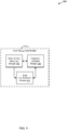
FIG. 1 , a block diagram illustrates an example of awireless communications system 100. Thesystem 100 includesbase stations 105,communication devices base station controller 135, and a core network 140 (thecontroller 135 may be integrated into the core network 140). Thesystem 100 may support operation on multiple carriers (waveform signals of different frequencies). Multi-carrier transmitters can transmit modulated signals simultaneously on the multiple carriers. For example, each modulated signal may be a multi-carrier channel modulated according to the various radio technologies described above. Each modulated signal may be sent on a different carrier and may carry control information (e.g., pilot signals, control channels, etc.), overhead information, data, etc. Thesystem 100 may be a multi-carrier LTE network capable of efficiently allocating network resources. - The
base stations 105 may wirelessly communicate with thedevices base stations 105 may communicate with thedevices base station controller 135 via multiple carriers. Each of thebase station 105 sites may provide communication coverage for a respective geographic area orcell 110. In some embodiments,base stations 105 may be referred to as a base transceiver station, a radio base station, an access point, a radio transceiver, a basic service set (BSS), an extended service set (ESS), a NodeB, eNodeB (eNB), Home NodeB, a Home eNodeB, or some other suitable terminology. The coverage area (or cell) for eachbase station 105 here is identified as 110-a, 110-b, or 110-c. The coverage area for a base station may be divided into sectors (not shown, but making up only a portion of the coverage area). Thesystem 100 may includebase stations 105 of different types (e.g., macro, pico, and/or femto base stations). A macro base station may provide communication coverage for a relatively large geographic area (e.g., 35 km in radius). A pico base station may provide coverage for a relatively small geographic area (e.g., 12 km in radius), and a femto base station may provide communication coverage for a relatively smaller geographic area (e.g., 50 m in radius). There may be overlapping coverage areas for different technologies. - The
devices coverage areas 110. Eachdevice devices links - Some of the
devices 115 may be machine type communication (MTC)devices 115 that perform various functions, capture information, and/or communicate information with limited or no human intervention. For example,MTC devices 115 may include sensors and/or meters for monitoring and/or tracking other devices, environmental conditions, etc.MTC devices 115 may be standalone devices or, in other embodiments,MTC devices 115 may be modules incorporated in other devices, such asrelay devices 120, which may in some cases be mobile devices or user equipments (UEs). For example,relay devices 120 such as smart phones, cellular phones and wireless communications devices, personal digital assistants (PDAs), tablets, other handheld devices, netbooks, ultrabooks, smartbooks, notebook computers, surveillance cameras, handled medical scanning devices, home appliances, etc. may include one or more MTC device modules. In other cases,relay devices 120 may not implement any MTC functionality. In the ensuing description, various techniques are described as applied to communications and processing for asystem 100 including a network and one ormore MTC devices 115. It should be understood that the described techniques may be advantageously applied to other devices such as those incorporatingMTC devices 115 and/or other wireless communication devices. - In some embodiments, an
MTC device 115 may communicate with abase station 105 by transmitting information through arelay device 120 on one or more narrow frequency bands to be relayed to abase station 105 on a broad frequency band. In some cases, theMTC device 115 may relay uplink data to abase station 105 through narrowfrequency band link 145 to arelay device 120. Therelay device 120 may then forward the MTC data to thebase station 105 via broadfrequency band link 130. Thebase station 105 may also communicate directly with theMTC device 115 vialink 125. - The information collected by the
MTC devices 115 may be transmitted across a network that includes components ofsystem 100 to a back-end system, such as a server. The transmission of data to/from theMTC devices 115 may be routed through thebase stations 105. Thebase stations 105 may communicate with theMTC devices 115 on a forward or downlink link for transmitting signaling and/or information to theMTC devices 115 and a reverse or uplink link for receiving signaling and/or information from theMTC devices 115. - In one example, the
network controller 135 may be coupled to a set ofbase stations 105 and provide coordination and control for thesebase stations 105. Thecontroller 135 may communicate with thebase stations 105 via a backhaul (e.g., core network 140). Thebase stations 105 may also communicate with one another directly or indirectly and/or via wireless or wireline backhaul. - The different aspects of
system 100, such as theMTC devices 115, therelay devices 120, thebase stations 105, thecore network 140, and/or thecontroller 135 may be configured for improving uplink communications of anMTC device 115. In one configuration, arelay device 120 may relay communications received from theMTC device 115 to a second device, such as abase station 105. The communications may be transmitted from theMTC device 115 to therelay device 120 via narrowfrequency band link 145. Therelay device 120 may relay the communications to thebase station 105 via broadfrequency band link 130. - In one aspect, an
MTC device 115 may initiate a discovery operation on a first narrow frequency band. In another aspect, therelay device 120 may initiate discovery on a first narrow frequency band by transmitting a discovery message to one ormore MTC devices 115. The first narrow frequency band may be a common narrow frequency tomultiple MTC devices 115. As a result, the discovery process may be initiated by anMTC device 115 or arelay device 120. Following discovery, communications may be established between therelay device 120 and theMTC device 115. Therelay device 120 may receive MTC data from theMTC device 115 over acommunication link 145 on a second narrow frequency band. Therelay device 120 may then relay the MTC data to abase station 105 over asecond communication link 130 on a broad frequency band. - In some cases, the first and/or second narrow frequency band of
communication link 145 may have a bandwidth in the range from 1.4 to 3 MHz, while the broad frequency band ofcommunication link 130 may have a bandwidth of 5 MHz, 10 MHz, 20 MHz, or other wide frequency bandwidth. -
FIG. 2 illustrates an example of awireless communication system 200 including a Radio Access Network (RAN) orCore Network 205 implementing a machine type communication service according to one aspect. Thesystem 200 may include any number ofMTC devices 115, however for ease of explanation only three MTC device 115-a, 115-b, and 115-c are shown in communication with anMTC server 210. Communications between theserver 210 and MTC devices 115-a, 115-b, and 115-c may be routed through a base station 105-a that may be considered part of the Core Network/RAN 205. The base station 105-a may be an example of thebase stations 105 illustrated inFIG. 1 . The MTC devices 115-a, 115-b, and 115-c may be examples of theMTC devices 115 illustrated inFIG. 1 , or may be examples of modules of therelay devices 120 illustrated inFIG. 1 . One skilled in the art would understand that the quantity ofMTC devices 115, Core Networks/RANs 205, andMTC servers 210 shown inFIG. 2 is for illustration purposes only and should not be construed as limiting. - The
wireless communication system 200 may be operable to facilitate machine type communication between one ormore MTC devices 115 and/or one or more base stations 105-a. Machine type communication may include communications between one or more devices without human intervention. In one example, machine type communication may include the automated exchange of data between a remote machine, such as an MTC device 115-a, 115-b, 115-c, and a back-end IT infrastructure, such as theMTC server 210, without user intervention. The transfer of data from an MTC device 115-a, 115-b, 115-c to theMTC server 210 via the Core Network/RAN 205 (e.g., the base station 105-a) may be performed using reverse or uplink link communications. Data collected by the MTC devices 115-a, 115-b, 115-c (e.g., monitoring data, sensor data, meter data, etc.) may be transferred to theMTC server 210 on the uplink communications. - The transfer of data from the
MTC server 210 to an MTC device 115-a via the base station 105-a may be performed via forward or downlink link communications. The forward link may be used to send instructions, software/firmware updates, and/or messages to the MTC devices 115-a, 115-b, 115-c. The instructions may instruct the MTC devices 115-a, 115-b, 115-c to remotely monitor equipment, environmental conditions, etc. Machine type communication may be used with various applications such as, but not limited to, remote monitoring, measurement and condition recording, fleet management and asset tracking, in-field data collection, distribution, physical access control, and/or storage, etc. The base station 105-a may generate one or more forward link frames with a small number of channels to transmit instructions, software/firmware updates, and/or messages. The various MTC devices 115-a, 115-b, 115-c may wake up to monitor a specific frame when instructions or other data is included on a channel of that frame. - In one embodiment, the behavior of the MTC devices 115-a, 115-b, 115-c may be pre-defined. For example, the day, time, etc. to monitor another device and transmit the collected information may be pre-defined for an MTC device 115-a, 115-b, 115-c. For example, the MTC device 115-a may be programmed to begin monitoring another device and collect information about that other device at a first pre-defined time period. The MTC device 115-a may also be programmed to transmit the collected information at a second pre-defined time period. The behavior of an MTC device 115-a may be remotely programmed to the device 115-a.
- In some embodiments, one or more MTC devices 115-a, 115-b, 115-c may have data to send to the
MTC server 210, for example through the core network/RAN 205 via base station 105-a. In other cases, theMTC server 210 may request data from the one or more MTC devices 115-a, 115-b, 115-c. In either case, an MTC device 115-a, 115-b, 115-c may have uplink data to communicate to a base station 105-a to be relayed to theMTC server 210. Given that MTC devices 115-a, 115-b, 115-c may be narrow frequency band devices and/or have limited power resources, they may not be able to effectively and timely communicate data on the uplink to a base station 105-a and/or theMTC server 210. Communications, and particularly uplink communications of an MTC device 115-a, 115-b, 115-c may be improved by relaying MTC data to a relay device 120-b over a narrow frequency band, with the MTC data being forwarded by the relay device 120-b to the base station 105-a and/or the Core Network/RAN 205 via a broad frequency band. These relay techniques will be described in further detail below in reference toFIGs. 3-7 . -
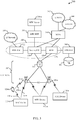
FIG. 3 illustrates an example of awireless communications system 300 implementing a machine type communication service over an LTE/LTE-Advanced network in accordance with various embodiments. The LTE/LTE-A network may include Evolved Universal Terrestrial Radio Access Network (E-UTRAN) 305 and Evolved Packet Core (EPC) 320. TheLTE E-UTRAN 305 andEPC 320 may be configured for supporting end-to-end packet-switched communications.EPC 320 may include a Packet Data Network (PDN) Gateway 322. The PDN Gateway 322 may be connected to one or more Internet Protocol (IP)Networks 330.IP Networks 330 may include Operator IP Networks as well as external IP Networks. For example,IP Networks 330 may include the Internet, one or more Intranets, an IP Multimedia Subsystem (IMS), and a Packet Switched (PS) Streaming Service (PSS). The PDN Gateway 322 may provide UE IP address allocation as well as other functions. TheEPC 320 may interconnect with other access networks using other Radio Access Technologies (RATs). For example,EPC 320 may interconnect withUTRAN 342 and/orGERAN 344 via one or more Serving GPRS Support Nodes (SGSNs) 340. -
EPC 320 may include one ormore Serving Gateways 324 and/or Mobility Management Entities (MME) 326. TheServing Gateway 324 may handle the interface to E-UTRAN 305 and provide a communication point for inter-RAT mobility (e.g., handover toUTRAN 342 and/orGERAN 344, etc.). Generally, theMME 326 may provide bearer and connection management while theServing Gateway 324 may transfer user IP packets betweenbase stations 105 and other network end-points (e.g., PDN GW 322, etc.). For example,MME 326 may manage intra-RAT mobility functions (e.g., Serving Gateway selection) and/or UE tracking management. TheServing Gateway 324 and theMME 326 may be implemented in one physical node ofEPC 320 or in separate physical nodes. A Home Subscriber Service (HSS) and/or home location register (HLR)node 360 may provide service authorization and/or user authentication for UEs. HSS/HLR node 360 may communicate with one ormore databases 362. -
E-UTRAN 305 may include one or more base stations or eNBs 105-b, 105-c which provide user and control plane protocol terminations for MTC devices 115-d, 115-e, 115-f, and/or a relay device or UE 120-b over the air interface of the LTE network. Base stations 105-b, 105-c may be connected with an X2 interface for intra-eNB communication. Base stations 105-b, 105-c may be connected to ServingGateway 324 and/orMME 326 over an S-1interface 315 for communicating data traffic and/or control plane information. The MTC devices 115-d, 115-e, 115-f, and/or the relay device 120-b may be configured to collaboratively communicate withmultiple base stations 105 through, for example, Multiple Input Multiple Output (MIMO), Coordinated Multi-Point (CoMP), or other schemes as described in more detail below. The MTC devices 115-d, 115-e, 115-f may be examples of theMTC devices 115 ofFIGs. 1 and/or 2. Similarly, the base stations 105-b, 105-c may be examples of thebase station 105 ofFIGs. 1 and/or 2. - In some embodiments,
wireless communications system 300 includes an MTC inter-working function (IWF)module 350, which may provide an interface betweenEPC 320 and one or more external MTC Servers 210-a for providing MTC service within the LTE network. MTC server 210-a may be an example ofMTC server 210 ofFIG. 2 . MTC server 210-a may be operated by the proprietor ofMTC devices 115 and may perform functions associated with deployment ofMTC devices 115 such as receiving and processing MTC device data. MTC server 210-a may be connected directly toEPC 320 or may be connected throughMTC IWF module 350 and/or other networks such as the Internet.MTC IWF module 350 may be implemented in one or more existing physical nodes of the EPC 320 (e.g., ServingGateway 324, etc.), or in a separate physical node connected toEPC 320. -
Wireless communications system 300 may further support relay of communications from an MTC device 115-d to a base station 105-b through a relay device 120-b. In one aspect, an MTC device 115-d may perform a discovery operation on a first narrow frequency band. The MTC device 115-d may then establish a first communication link 145-a with a discovered relay device 120-b on a second narrow frequency band. In some cases, the first narrow frequency band may be the same as the second narrow frequency band. The second narrow frequency band may be common to a plurality of narrow frequency band wireless devices, such asmultiple MTC devices 115. The MTC device 115-d may then transmit MTC data on the first communication link 145-a to the discovered relay device 120-b. The relay device 120-b may then relay the MTC data to a base station 105-b on a second communication link 130-a, which may be on a broad frequency band. In some cases the first and/or second narrow frequency band of the first communication link 145-a may be a subset, e.g., within, the broad frequency band of the second communication link 130-a. As a result of the narrow and broad frequency bands occupying the same frequency resources, communications over both the second frequency band via the first communication link 145-a and the broad frequency band via the second communication link 130-a by the relay device 120-b may overlap in time. -
FIG. 4 illustrates an example ofwireless communications 400 between an MTC device 115-g, a relay device 120-c, and a base station 105-d in accordance with various embodiments. The MTC device 115-g may be an example of theMTC device 115 ofFIGs. 1 ,2 , and/or 3. The relay device 120-c may be an example of the relay device orUE 120 ofFIGs. 1 and/or 3. The base station 105-d, which may be a cellular base station, eNB, or WLAN access point, may be an example ofbase station 105 ofFIGs. 1 ,2 , an/or 3. The MTC device 115-g may first engage in a discovery process by sending/receiving one or more discovery messages to/from a relay device 120-c at time T0. - In some cases, the MTC device 115-g may initiate the discovery process, for example if it has data to transmit to a base station 105-d and/or
MTC server 210, by sending a discovery signal to the relay device 120-c over a firstnarrow frequency band 405. In some cases, theMTC device 115 may select the firstnarrow frequency band 405 or the firstnarrow frequency band 405 may be predetermined and known by relay devices 120-c. In this scenario, the relay device 120-c may then respond to the discovery signal via the same firstnarrow frequency band 405. - In other cases, the relay device 120-c may initiate the discovery process, for example, by broadcasting a discovery signal on the first
narrow frequency band 405, which may be common to a plurality of MTC devices. The MTC device 115-g may listen to the firstnarrow frequency band 405 and respond to the discovery signal over the same firstnarrow frequency band 405. - Following the discovery process at time T1, the MTC device 115-g and the relay device 120-c may establish a first link, such as an access link, over a second
narrow frequency band 410. In some cases the secondnarrow frequency band 410 may be the same as the firstnarrow frequency band 405. In one configuration, the access link may be an LTE-D connection. - The MTC device 115-g may transmit data over the access link via the second
narrow frequency band 410 to the relay device 120-c to be relayed to the base station 105-d. The relay device 120-c may establish, or in some cases have already established, a second communication link, or relay link, with the base station 105-d utilizing abroad frequency band 415. The relay device 120-c may forward the MTC data to the base station 105-d via thebroad frequency band 415 of the relay link. In one configuration, the relay link is an LTE connection. - In some cases, communications over
narrow frequency band 410 andbroad frequency band 415 may happen concurrently so that the relay device 120-c may maintain active connections with the MTC device 115-g and the base station 105-d simultaneously. As a result, MTC data may be relayed to a base station 105-d with little impact on the operation of the relay device or UE 120-c. - In some embodiments, discovery signaling over the first
narrow frequency band 405 and/or uplink data transmitted from the MTC device 115-g to the relay device 120-c over the secondnarrow frequency band 410 may be communicated vialink 145 described above in reference toFIGs. 1 and/or 3. Similarly, the MTC data forwarded from the relay device 120-c to the base station 105-d over thebroad frequency band 415 may be communicated vialink 130 described above in reference toFIGs. 1 and/or 3. -
FIG. 5 illustrates a time-frequency diagram 500 of communications between the MTC device 115-g, the relay device 120-c, and the base station 105-d ofFIG. 4 . In one embodiment, the MTC device 115-g may engage with, e.g., send/receive discovery messages to/from the relay device 120-c over narrow frequency band 405-a. Narrow frequency band 405-a may correspond to the firstnarrow frequency band 405 described in reference toFIG. 4 . Communications over narrow frequency band 405-a may begin attime 505 and end attime 510, for example representing time spent in the discovery process. Frequency band 405-a may span a frequency bandwidth from afirst frequency 535 to asecond frequency 540, which may represent, for example a bandwidth of 1.4 MHZ. In one embodiment, thefirst frequency 535 may be 1923 MHz and thesecond frequency 540 may be 1924.4 MHz. In other embodiments, frequency band 405-a may span different bandwidths and on different frequencies according to the operation or configuration of the MTC device 115-g and the relay device 120-c, etc. - In some embodiments, communications from the MTC device 115-g to the relay device 120-c over the second narrow frequency band may be represented by second narrow frequency band 410-a. Second narrow frequency band 410-a may be an example of the second
narrow frequency band 410 described in reference toFIG. 4 . Communications over the second narrow frequency band 410-a may begin attime 505 and end attime 510. The time period for communications over the second narrow frequency band 410-a may represent the transmission time of MTC data from the MTC device 115-g to the relay device 120-c. Second narrow frequency band 410-a may span a frequency bandwidth from afirst frequency 525 to asecond frequency 530, which may represent, for example a bandwidth of 1.4 MHZ. In one embodiment,first frequency 525 may represent 1920 MHz andsecond frequency 530 may represent 1921.4 MHz. In other embodiments, second narrow frequency band 410-a may span different bandwidths and on different frequencies according to the operation or configuration of the MTC device 115-g and the relay device 120-c, etc. - Once the relay device 120-c receives the MTC data to be forwarded/relayed to the base station 105-d, or concurrently therewith, the
relay device 120 may transmit the MTC data to the base station 105-d via a broad frequency band 415-a. Broad frequency band 415-a may be an example of thebroad frequency band 415 described in reference toFIG. 4 . Communications over the broad frequency band 415-a may begin attime 515 and end attime 520. Broad frequency band 415-a may span a frequency bandwidth fromfirst frequency 525 tosecond frequency 545, which may represent, for example a bandwidth of 5 MHZ. In one embodiment, thefirst frequency 525 may represent 1920 MHz and thesecond frequency 545 may represent 1925 MHz. - In other embodiments, broad frequency band 415-a may span different bandwidths and on different frequencies according to the operation or configuration of the MTC device 115-g and the relay device 120-c. In one configuration, the broad frequency band 415-a may encompass both the first narrow frequency band 405-a used for discovery and the second narrow frequency band 410-a used to transmit MTC data from the MTC device 115-g to the relay device 120-c. As a result, the relay device 120-c may communicate to both the MTC device 115-g and the base station 105-d using concurrently active links, such as
links FIGs. 1 and/or 3. - In some embodiments, communications over frequency bands 410-a and 415-a may occur at the same time. In other cases, communications over frequency bands 410-a and 415-a may occur at different times.
- In some cases, discovery signaling over a first narrow frequency band 405-a and/or uplink data transmitted from the MTC device 115-g to the relay device 120-c over the second narrow frequency band 410-a may be communicated via
link 145 described above in reference toFIGs. 1 and/or 3. Similarly, the MTC data forwarded from the relay device 120-c to the base station 105-d over the broad frequency band 415-a may be communicated vialink 130 described above in reference toFIGs. 1 and/or 3. - Turning next to
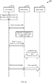
FIG. 6 , a flow diagram 600 illustrates an example of an MTC device 115-h relaying communications to a base station 105-e through a relay device 120-d in accordance with various embodiments. The MTC device 115-h may be an example of theMTC device 115 ofFIGs. 1 ,2 ,3 , and/or 4. The relay device 120-d may be an example of therelay device 120 ofFIGs. 1 ,3 , and/or 4. The base station 105-e, which may be a cellular base station, eNB, or WLAN access point, may be an example ofbase station 105 ofFIGs. 1 ,2 ,3 , and/or 4. - In some embodiments, an MTC device 115-h may determine a first narrow frequency band for
discovery 605, for example based on a device ID of the MTC device 115-h. In some cases, the first narrow frequency band may be predefined, for example by the device ID of the MTC device 115-h or by theMTC server 210, base station 105-e, and/or the relay device 120-d. In other cases, the first narrow frequency band may be randomly selected by the MTC device 115-h, such as from a list of available frequency bands. The MTC device 115-h may participate in adiscovery process 610 with the relay device 120-d utilizing the determined first narrow frequency band. Participating in thediscovery process 610 may include sending, by the MTC device 115-h, one or more discovery signals to the relay device 120-d, and receiving a response message from the relay device 120-d indicating that the relay device 120-d is available to serve as a relay. The relay device 120-d may then determine a second narrow frequency band to establish alink 615 with the MTC device 115-h to facilitate relaying communications to the base station 105-e. In other embodiments, the MTC device 115-h either alone or in combination with the relay device 120-d, may determine the second narrow frequency band for the link establishment between the MTC device 115-h and the relay device 120-d. In some cases, the second narrow frequency band may be predefined, for example by the MTC device 115-h, theMTC server 210, base station 105-e, and/or the relay device 120-d. The relay device 120-d and the MTC device 115-h may then establish the link, which may also be referred to as an access link, over the secondnarrow frequency band 620. In some cases, the first and second narrow frequency bands may be the same. The first or second narrow frequency bands may be common to a plurality of devices, such asMTC devices 115 and may be predetermined for discovery and/or communications withMTC devices 115. - In some embodiments 120-d, the relay device 120-d may establish a broad
frequency band link 630 to enable the relay device 120-d to relay communications from the MTC device 115-h to the base station 105-e. Establishing the broadfrequency band link 630 may include performing synchronization with the base station 105-e. In some cases, the broad frequency band link between the relay device 120-d and the base station 105-e may be referred to as a relay link. Once the access link has been established 620 between the MTC device 115-h and the relay device 120-d and the relay link has been established 630 between the relay device 120-d and the base station 105-e, the MTC device 115-h may then perform communications with the base station 105-e through the relay device 120-d. In particular, the MTC device 115-h may first transmit data over the narrowfrequency band link 635 to the relay device 120-d. The relay device 120-d may concurrently or subsequently, relay data over the broadfrequency band link 640 to the base station 105-e. - In some embodiments, participating in the
discovery process 610 and/or establishing the narrow frequency band or access link 620 may be carried out overlink 145 described in reference toFIGs. 1 and/or 3, and/or over the firstnarrow frequency band 405 described in reference toFIGs. 4 and/or 5. In some the embodiments, establishing the narrow frequency band oraccess link 620 and/or transmitting data over the narrow frequency band link to be relayed 635 may be carried out overlink 145 described in reference toFIGs. 1 and/or 3, and/or over the secondnarrow frequency band 410 described in reference toFIGs. 4 and/or 5. Establishment of the broad frequency band orrelay link 630 and/or relaying data over the broadfrequency band link 640 may be carried out overlink 130 described in reference toFIGs. 1 and/or 3, and/or over thebroad frequency band 415 described in reference toFIGs. 4 and/or 5. - Turning next to
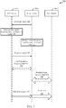
FIG. 7 , a flow diagram 700 illustrates an example of an MTC device 115-i for relaying communications to a base station 105-f through a relay device 120-e in accordance with various embodiments. The MTC device 115-i may be an example of theMTC device 115 ofFIGs. 1 ,2 ,3 ,4 , and/or 6. The relay device 120-e may be an example of the relay device orUE 120 ofFIGs. 1 ,3 ,4 , and/or 6. The base station 105-f, which may be a cellular base station, eNB, or WLAN access point, may be an example ofbase station 105 ofFIGs. 1 ,2 ,3 ,4 , and/or 6. - In some embodiments, a relay device 120-e may send one or
more discovery signals 705 to an MTC device 115-i, for example, if the relay device 120-e detects that the MTC device 115-s is nearby and/or has data to transmit to a base station 105-f and/orMTC server 210. In other cases, the base station 105-f, for example acting at the direction of anMTC server 210, may communicate to the relay device 120-e that it has data to transmit and/or wants to establish relay communications with the MTC device 115-i. The relay device 120-e may send adiscovery signal 705 to the MTC device 115-i over a first narrow frequency band, which may be common to a plurality ofMTC devices 115. In some cases, the relay device 120-e may broadcast the discovery signal on the common narrow frequency band tomultiple MTC devices 115, or may transmit the discovery signal on multiple narrow frequency bands either simultaneously or one at a time to one ormore MTC devices 115. - The MTC device 115-i may be listening on the first
narrow band frequency 710, which may be a predetermined narrow frequency band for discovery purposes. After the discovery signal is sent 705 by the relay device 120-e, the relay device 120-e may monitor one or more narrow frequency bands, such as a first and/or a second narrow frequency band for apredetermined time 715 for a response from the MTC device 115-i. After receiving thediscovery signal 705 sent by the relay device 120-e, the MTC device 115-i may then send aresponse signal 720 to the relay device 120-e to indicate confirmation of the relay. In some cases, if thediscovery signal 705 was sent over a common narrow frequency band, the MTC device 115-i may send theresponse signal 720 over a second narrow frequency band different from the common narrow frequency band. In other cases, if thediscovery signal 705 sent by the relay device 120-e was over a first narrow frequency band not common tomultiple MTC devices 115, the MTC may send theresponse signal 720 over the same first narrow frequency band. The MTC device 115-i and the relay device 120-e may then establish a narrow frequency band or access link 725 over the second narrow frequency band. In some cases, the first and second narrow frequency bands may be the same. - The relay device 120-e may establish a broad frequency band or
relay link 730 with the base station 105-f. In some cases, the first and/or second narrow frequency bands may be a subset of the broad frequency band. Once theaccess link 725 has been established between the MTC device 115-i and the relay device 120-e and therelay link 730 has been established between the relay device 120-e and the base station 105-f, the MTC device 115-i may then transmit data to the base station 105-f through the relay device 120-e. In particular, the MTC device 115-i may transmit data over the second narrow frequency band link to be relayed 735 to the base station 105-f. The relay device 120-e may relay the data over the broadfrequency band link 740 to the base station 105-f. - In some embodiments, sending one or more discovery signals 705, sending the
response signal 720, and/or establishing the narrow frequency band or access link 725 may be carried out overlink 145 described in reference toFIGs. 1 and/or 3, and/or over the firstnarrow frequency band 405 described in reference toFIGs. 4 and/or 5. In some the embodiments, establishing the narrow frequency band oraccess link 725 and/or transmitting data over the narrow frequency band link to be relayed 735 may be carried out overlink 145 described in reference toFIGs. 1 and/or 3, and/or over the secondnarrow frequency band 410 described in reference toFIGs. 4 and/or 5. Establishment of the broad frequency band orrelay link 730 and/or relaying data over the broadfrequency band link 740 may be carried out overlink 130 described in reference toFIGs. 1 and/or 3, and/or over thebroad frequency band 415 described in reference toFIGs. 4 and/or 5. -
FIG. 8 shows a block diagram 800 of a device 115-j, which may be anMTC device 115, for relaying communications to abase station 105 through arelay device 120 in accordance with various embodiments. The device 115-j may be an example of one or more aspects of theMTC device 115 described above with reference toFIGs. 1 ,2 ,3 ,4 ,6 , and/or 7. The MTC device 115-j may communicate with arelay device 120 and/or abase station 105 vialinks 145 and/or 125 as described in reference toFIGs. 1 and/or 3 overfrequency bands 405 and/or 410 described in reference toFIGs. 4 and/or 5. The device 115-j may include anMTC receiver 805, alink management module 810, and/or anMTC transmitter 815. Each of these components may be in communication with each other. - The
MTC receiver 805 may receive information such as packet, data, and/or signaling information regarding what the device 115-j has received or transmitted. The received information may be utilized by thelink management module 810 for a variety of purposes. In some cases, theMTC receiver 805 may be configured to receive data or transmissions, for example from arelay device 120, to further enable the various techniques described above for relaying communications to abase station 105 through arelay device 120. - The
MTC transmitter 815 may similarly transmit information such as packet, data, and/or signaling information from the device 115-j. In some cases, theMTC transmitter 815 may be configured to send uplink data according to various embodiments described herein, such to abase station 105 through arelay device 120. - In one embodiment, the
MTC receiver 805 may be configured to receive one or more discovery signals from arelay device 120 over a first narrow frequency band. TheMTC receiver 805 may then communicate the one or more discovery signals to thelink management module 810. Thelink management module 810 may configure a response message to the one or more received discovery signals, such as to request therelay device 120 to serve as a relay for uplink communications to abase station 105. Thelink management module 810 may communicate the response message to theMTC transmitter 815. Thetransmitter 815 may transmit the response message to therelay device 120 over the first or a second narrow frequency band. - In some cases, when the MTC device 115-j initiates the discovery process with the
relay device 120, thelink management module 810 may configure one or more discovery signals to be transmitted to arelay device 120. Thelink management module 810 may communicate the discovery signals to theMTC transmitter 815. Thetransmitter 815 may broadcast the discovery signals to one ormore relay devices 120 over a first narrow frequency band. In this scenario, theMTC receiver 805 may then receive confirmation from one ormore relay devices 120 that they are available to serve as a relay. The confirmation may be received over the first or a second narrow frequency band. - Following the discovery process, the
link management module 810 may compile and/or configure data to be relayed through therelay device 120 to abase station 105. Thelink management module 810 may communicate the data to theMTC transmitter 815 to send to therelay device 120 over a second narrow frequency band. -
FIG. 9 is a block diagram 900 illustrating one embodiment of a link management module 810-a. The link management module 810-a may be an example of thelink management module 810 ofFIG. 8 . In one example, the link management module 810-a may include a relaydevice discovery module 905, afrequency selection module 910, and/or a link establishment module 915. - The relay
device discovery module 905 may configure and coordinate discovery communications with arelay device 120 via the MTC transmitter andreceiver FIG. 8 . This may include configuring discovery signals and/or discovery response signals as described in greater detail in reference toFIGs. 4, 5 ,6 , and/or 7 above. - In some embodiments, the
frequency selection module 910 may operate in conjunction with the relaydevice discovery module 905 to coordinate the discovery process with arelay device 120. For example, when the MTC device 115-j initiates discovery with arelay device 120, the frequency selection module may select a first narrow frequency band on which to transmit a discovery request. In another example, when therelay device 120 initiates discovery, thefrequency selection module 910 may select a narrow frequency band, such as a first or second narrow frequency band, upon which to respond to the discovery signal. The discovery signal may be broadcast from therelay device 120 tomultiple MTC devices 115 over a first common narrow frequency band. In this scenario, thefrequency selection module 910 may select a second narrow frequency band to send a response signal. In another scenario, therelay device 120 may transmit multiple discovery signals on multiple narrow frequency bands, such that the MTC device 115-j receives a discovery signal on a first narrow frequency band. Thefrequency selection module 910 may then select the same first narrow frequency band to transmit the response. Thefrequency selection module 910 may coordinate with the relaydevice discovery module 905, theMTC receiver 805 and/or theMTC transmitter 815 of MTC device 115-j to effectuate discovery. - Once discovery with a
relay device 120 is complete, the relaydevice discovery module 905 may communicate to thefrequency selection module 910 and the link establishment module 915 that a communication link may be established. - The
frequency selection module 910 may determine one or more narrow frequency bands on which the MTC device 115-j will communicate MTC data to therelay device 120. In some cases, selection of a narrow frequency band for MTC data communications may be determined based on which narrow frequency band(s) was used for discovery. Thefrequency selection module 910 may communicate narrow frequency band information to the link establishment module 915. - The link establishment module 915 may coordinate with the
MTC transmitter 815 and theMTC receiver 805 to establish a peer to peer connection (P2P) with therelay device 120 over the narrow frequency band selected by thefrequency selection module 910. The link establishment module 915 may communicate with theMTC transmitter 815 to send uplink data over a narrow frequency band, to therelay device 120. -
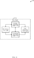
FIG. 10 shows a block diagram 1000 of a device 120-f, which may be a relay device, for relaying communications from anMTC device 115 to abase station 105 in accordance with various embodiments. The device 120-f may be an example of one or more aspects of therelay device 120 described above with reference toFIGs. 1 ,3 ,4 ,6 , and/or 7. The relay device 120-f may communicate with anMTC device 115 and/or abase station 105 vialinks FIGs. 1 and/or 3 overfrequency bands FIGs. 4 and/or 5. The relay device 120-f may include arelay device receiver 1005, arelay module 1010, and/or arelay device transmitter 1015. Each of these components may be in communication with each other. - The
relay device receiver 1005 may receive information such as packet, data, and/or signaling information regarding what the device 120-f has received or transmitted. The received information may be utilized by therelay module 1010 for a variety of purposes. In some cases, therelay device receiver 1005 may be configured to receive data or transmissions, for example from anMTC device 115 and/or abase station 105, to further enable the various techniques described above for relaying communications from anMTC device 115 to abase station 105. - The
relay device transmitter 1015 may transmit information such as packet, data, and/or signaling information from the device 120-f. In some cases, therelay device transmitter 1015 may be configured to relay data received from anMTC device 115 to abase station 105. - The
relay device receiver 1005 may receive one or more discovery signals from anMTC device 115 over a first and/or second narrow frequency band. Therelay device receiver 1005 may communicate the one or more discovery signals to therelay module 1010. Therelay module 1010 may configure a response message indicating that the device 120-f is available to serve as a relay for theMTC device 115. The response message may be transmitted to theMTC device 115 over the first or second narrow frequency band. - In other embodiments, device 120-f may initiate discovery with an
MTC device 115. In this case, therelay module 1010 may configure one or more discovery signals and communicate the discovery signals to therelay device transmitter 1015. The discovery signals may be transmitted to theMTC device 115 over a first narrow frequency band. In one embodiment, the first narrow frequency band may be a common narrow frequency band formultiple MTC devices 115. Therelay device receiver 1005 may receive a request to serve as a relay from anMTC device 115. - Once the relay relationship has been confirmed between the relay device 120-f and the
MTC device 115, therelay device receiver 1005 may receive data from the discoveredMTC device 115 on a narrow frequency band. Therelay device receiver 1005 may communicate the data to therelay module 1010, whereby therelay module 1010 may configure the data to be transmitted to thebase station 105 over a broad frequency band. Therelay module 1010 may communicate the data to be relayed to therelay device transmitter 1015. The data may be relayed to thebase station 105 over the broad frequency band. -
FIG. 11 is a block diagram 1100 illustrating one embodiment of a relay module 1010-a. The relay module 1010-a may be an example of therelay module 1010 ofFIG. 10 . In one example, the relay module 1010-a may include anMTC discovery module 1105, a firstlink management module 1110, a secondlink management module 1115, and/or arelay coordination module 1120. - In particular, the
MTC discovery module 1105 may, configure one or more discovery messages to be communicated to anMTC device 115 to establish a first communication link with theMTC device 115 over a first and/or second narrow frequency band. The first communication link may be an example oflink 145 as described above in reference toFIGs. 1 and/or 3 overfrequency bands 405 and/or 410 as described above in reference toFIGs. 4 and/or 5. As the discovery process has already been described in detail above in reference toFIGs. 4, 5 ,6 , and7 , for the sake of brevity, it will not be described again here. - Once the device 120-f and the
MTC device 115 have discovered each other, theMTC discovery module 1105 may communicate to the firstlink establishment module 1110 and the secondlink establishment module 1115 to initialize links for relaying data from theMTC device 115 to abase station 105. The firstlink establishment module 1110 may establish a first link with theMTC device 115 over a narrow frequency band. The first communication link may be an example oflink 145 as described above in reference toFIGs. 1 and/or 3 overfrequency bands 405 and/or 410 as described above in reference toFIGs. 4 and/or 5. The secondlink establishment module 1115 may establish a second link with thebase station 105. The second link may be an example oflink 130 as described above in reference toFIGs. 1 and/or 3 overfrequency band 415 as described above in reference toFIGs. 4 and/or 5. - Once the first and second links are established, the first and second
link establishment modules relay coordination module 1120 to begin relaying data from theMTC device 115 to thebase station 105. Therelay coordination module 1120 may receive data to be relayed from theMTC device 115 over a narrow frequency band. The data may be relayed to thebase station 105 over the broad frequency band. In one configuration, therelay device receiver 1005 may receive data from theMTC device 115 over the first link via a narrow frequency band and therelay device transmitter 1015 may transmit data to thebase station 105 over the second link via a broad frequency band. -
FIG. 12 is a block diagram 1200 of an MTC device 115-k configured for sending communications, and particularly uplink communications, to abase station 105 through arelay device 120 in accordance with various embodiments. The MTC device 115-k may have any of various configurations, such as a sensor or monitor 1205 for various MTC applications discussed above. The MTC device 115-k may have an internal power supply (not shown), such as a small battery, to facilitate mobile operation. In some embodiments, the MTC device 115-k may be an example of and/or incorporate one or more aspects of theMTC device 115 ofFIGs. 1 ,2 ,3 ,4 ,6 ,7 ,8 , and/or 9. The MTC device 115-k may be a multi-mode mobile device. The MTC device 115-k may be referred to as an MTC UE or M2M device in some cases. - The MTC device 115-k may include a link management module 810-b, antenna(s) 1210, a
transceiver module 1215,memory 1220, and aprocessor module 1225, which each may be in communication, directly or indirectly, with each other (e.g., via one or more buses). Thetransceiver module 1215 may be configured to communicate bi-directionally, via the antenna(s) 1210 and/or one or more wired or wireless links, with one or more networks, as described above. For example, thetransceiver module 1215 may be configured to communicate bi-directionally withrelay devices 120 ofFIGs. 1 ,3 ,4 ,6 ,7 ,9 , and/or 10 and/orbase stations 105 ofFIGs. 1 ,2 ,3 ,4 ,6 , and/or 7. Thetransceiver module 1215 may include a modem configured to modulate the packets and provide the modulated packets to the antenna(s) 1210 for transmission, and to demodulate packets received from the antenna(s) 1210. While the MTC device 115-k may include asingle antenna 1210, the MTC device 115-k may includemultiple antennas 1210 for multiple transmission links. - The
memory 1220 may include random access memory (RAM) and read-only memory (ROM). Thememory 1220 may store computer-readable, computer-executable software code 1230 containing instructions that are configured to, when executed, cause theprocessor module 1225 to perform various functions described herein (e.g., data capture, database management, message routing, etc.). Alternatively, thesoftware code 1230 may not be directly executable by theprocessor module 1225 but be configured to cause the computer (e.g., when compiled and executed) to perform functions described herein. - The
processor module 1225 may include an intelligent hardware device, e.g., a central processing unit (CPU) such as an ARM® based processor or those made by Intel® Corporation or AMD®, a microcontroller, an application specific integrated circuit (ASIC), etc. - According to the architecture of
FIG. 12 , the MTC device 115-k may further include acommunications management module 1235. Thecommunications management module 1235 may manage communications withbase stations 105,other MTC devices 115, and/orrelay devices 120. By way of example, thecommunications management module 1235 may be a component of the MTC device 115-k in communication with some or all of the other components of the MTC device 115-k via a bus. Alternatively, functionality of thecommunications management module 1235 may be implemented as a component of thetransceiver module 1215, as a computer program product, and/or as one or more controller elements of theprocessor module 1225. - The components for MTC device 115-k may be configured to implement aspects discussed above with respect to
devices 115 ofFIGs. 1 ,2 ,3 ,4 ,6 ,7 ,8 , and/or 9 and may not be repeated here for the sake of brevity. For example, the link management module 810-b may include similar functionality aslink management module 810 ofFIGs. 8 and/or 9. The link management module 810-b may enable the MTC device 115-k to discovery and relay data to arelay device 120 on a first and second narrow frequency band, the data then relayed to thebase station 105 by therelay device 120 via a broad frequency band. - In some embodiments, the
transceiver module 1215 in conjunction with antenna(s) 1210, along with other possible components of MTC device 115-k, may receive transmissions from one ormore relay devices 120 and may transmit uplink data to thebase stations 105 or acore network 140 by relaying the data through one ormore relay devices 120. In some embodiments, thetransceiver module 1215, in conjunction withantennas 1210 along with other possible components of MTC device 115-k, may receive transmissions from one ormore relay devices 120 and may transmit uplink data tobase stations 105 or acore network 140 such that these devices or systems may utilize flexible waveforms. - In some embodiments, the MTC device 115-k may not have a power amplifier. In other cases, the MTC device 115-k may have a limited power amplifier. In either case, the communication range of the MTC device 115-k may be limited. For this and other reasons, the ability of the MTC device 115-k to communicate uplink information, for example to a
base station 105 or MTC server 10, may be limited. As a result, the techniques described above for relaying communications from the MTC device 115-k through arelay device 120 over a narrow frequency band tobase station 105 over a broad frequency band may improve uplink communications for the MTC device 115-k. -
FIG. 13 shows a block diagram 1300 of a relay device 120-g configured for relaying communications from anMTC device 115 to abase station 105 in accordance with various embodiments. The relay device 120-g may have various configurations and may be included or be part of a personal computer (e.g., a laptop computer, netbook computer, tablet computer, etc.), a cellular telephone, a PDA, a digital video recorder (DVR), an internet appliance, a gaming console, an e-reader, etc. The relay device 120-g may in some cases have an internal power supply (not shown), such as a small battery, to facilitate mobile operation. In some embodiments, the relay device 120-g may be an example of one or more aspects of one of thedevices 120 described with reference toFIG. 1 ,3 ,4 ,6 ,7 ,10 , and/or 11. The relay device 120-g may be configured to implement at least some of the features and functions described with reference toFIG. 4, 5 ,6 and/or 7. - The relay device 120-g may include a relay module 1010-b, a
processor module 1305, amemory module 1310, at least onetransceiver module 1315, at least oneantenna 1320, and/or acommunication management module 1325. Each of these components may be in communication with each other, directly or indirectly. - The
memory module 1310 may include random access memory (RAM) and/or read-only memory (ROM). Thememory module 1310 may store computer-readable, computer-executable software (SW)code 1330 containing instructions that are configured to, when executed, cause theprocessor module 1305 to perform various functions described herein for communicating over a wireless communications system. Alternatively, thesoftware code 1330 may not be directly executable by theprocessor module 1305 but may be configured to cause the relay device 120-g (e.g., when compiled and executed) to perform various of the functions described herein. - The
processor module 1305 may include an intelligent hardware device, e.g., a central processing unit (CPU) such as an ARM® based processor or those made by Intel® Corporation or AMD®, a microcontroller, an ASIC, etc. Theprocessor module 1305 may process information received through the transceiver module(s) 1315 and/or information to be sent to the transceiver module(s) 1315 for transmission through the antenna(s) 1320. Theprocessor module 1305 may handle, alone or in connection with thecommunication management module 1325, various aspects of communicating over a wireless communications system and/or detecting a communications network. - The transceiver module(s) 1315 may include a modem configured to modulate packets and provide the modulated packets to the antenna(s) 1320 for transmission, and to demodulate packets received from the antenna(s) 1320. The transceiver module(s) 1315 may in some cases be implemented as one or more transmitter modules and one or more separate receiver modules. The transceiver module(s) 1315 may support communications in a first spectrum, such as a WWAN or cellular spectrum, and in a second spectrum, such as a WLAN spectrum. The transceiver module(s) 1315 may be configured to communicate bi-directionally, via the antenna(s) 1320, with one or more of the
MTC devices 115 ofFIGs. 1 ,2 ,3 ,4 ,6 ,7 ,8 , and/or 9 and/or base stations 105 (e.g., eNBs and/or WLAN access points) described with reference toFIG. 1 ,2 ,3 ,4 ,6 , and/or 7. While the relay device 120-g may include a single antenna, there may be embodiments in which the relay device 120-g may includemultiple UE antennas 1320. - The relay device 120-g may also include a
power amplifier 1330 that may allow the relay device 120-g to communicate over longer distances, for example withmore base stations 105, than, for example anMTC device 115. Because the relay device 120-g may have a longer communication range than anMTC device 115, it may be beneficial for anMTC device 115 to relay communications via the relay device 120-g to expand the base stations theMTC device 115 may communicate with, such as for example, that are greater distances from theMTC device 115. - The components of the relay device 120-g may be configured to implement aspects discussed above with respect to
devices 120 ofFIGs. 1 ,3 ,4 ,6 ,7 ,10 and/or 11 and may not be repeated here for the sake of brevity. For example, relay module 1010-b may include similar functionality as therelay module 1010 ofFIGs. 10 and/or 11. The relay module 1010-b may enable the relay device 120-g to discovery and relay data from anMTC device 115 over a first and second narrow frequency band to abase station 105 over a broad frequency band. - In some embodiments, the
transceiver module 1315 in conjunction with antenna(s) 1320, along with other possible components of relay device 120-g, may receive transmissions from one ormore MTC devices 115 and may relay uplink data from theMTC device 115 tobase stations 105 or acore network 140. In some embodiments, thetransceiver module 1315, in conjunction withantennas 1320 along with other possible components of relay device 120-g such as thepower amplifier 1330, may allow the relay device 120-g to receive transmissions from one ormore MTC devices 115 and transmit uplink data from theMTC device 115 tobase stations 105 or acore network 140. In some cases, relay device 120-g,MTC device 115,base stations 105, and/orcore network 140 may utilize flexible waveforms. -
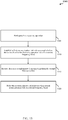
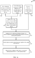
FIG. 14 is a flow chart illustrating one example of amethod 1400 for relaying communications from a first wireless device through a second wireless device to a third device in accordance with various embodiments. The first wireless device may be anMTC device 115. The second wireless device may be arelay device 120, and the third device may be abase station 105. For clarity, themethod 1400 is described below with reference to one or more aspects of one of the devices 115 (e.g., an MTC device) described with reference toFIGs. 1 ,2 ,3 ,4 ,6 ,7 ,8 ,9 , and/or 12. In some embodiments, a device such as one of thedevices 115 may execute one or more sets of codes to control the functional elements of thedevice 115 to perform the functions described below. - At
block 1405, anMTC device 115 may perform a discovery operation via a first narrow frequency band. The operation(s) atblock 1405 may in some cases be performed using thelink management module 810 described in reference toFIGs. 8 ,9 , and/or 12, the relaydevice discovery module 905 and/or thefrequency selection module 910 described in reference toFIG. 9 , and/or the MTC receiver and/ortransmitter FIG. 8 . - At
block 1410, a first communication link with a discovered second wireless device may be established on the second narrow frequency band. The operation(s) atblock 1410 may in some cases be performed using thelink management module 810 described in reference toFIGs. 8 ,9 , and/or 12, the link establishment module 915 and/or thefrequency selection module 910 described in reference toFIG. 9 , and/or the MTC receiver and/ortransmitter FIG. 8 . - At
block 1415, theMTC device 115 may transmit data on the second narrow frequency band to the discovered second wireless device to be relayed to the third device on a second communication link on a broad frequency band. The operation(s) atblock 1415 may in some cases be performed using thelink management module 810 described in reference toFIGs. 8 ,9 , and/or 12, the link establishment module 915 and/or thefrequency selection module 910 described in reference toFIG. 9 , and/or the MTC receiver and/ortransmitter FIG. 8 . - Thus, the
method 1400 may provide for relaying communications from anMTC device 115 to abase station 105 through arelay device 120. It should be noted that themethod 1400 is just one implementation and that the operations of themethod 1400 may be rearranged or otherwise modified such that other embodiments are possible. -
FIG. 15 is a flow chart illustrating one example of amethod 1500 for a first wireless device to relay communications received from a second wireless device to a third device in accordance with various embodiments. The first wireless device may be arelay device 120. The second wireless device may be anMTC device 115, and the third device may be abase station 105. For clarity, themethod 1500 is described below with reference to one or more aspects of one of therelay devices 120 described with reference toFIGs. 1 ,3 ,4 ,6 ,7 ,10 ,11 , and/or 13. In some embodiments, a device such as one of thedevices 120 may execute one or more sets of codes to control the functional elements of thedevice 120 to perform the functions described below. - At
block 1505, therelay device 120 may participate in a discovery operation, for example with anMTC device 115. The operation(s) atblock 1505 may in some cases be performed using therelay module 1010 described with reference toFIGs. 10 ,11 and/or 13, theMTC discovery module 1105 described with reference toFIG. 11 , and/or the relay device receiver and/ortransmitter FIG. 10 . - At
block 1510, a first communication link with the second wireless device involved in the discovery operation may be established via a first narrow frequency band. The operation(s) atblock 1510 may in some cases be performed using therelay module 1010 described with reference toFIGs. 10 ,11 and/or 13, theMTC discovery module 1105 and/or the firstlink management module 1110 described with reference toFIG. 11 , and/or the relay device receiver and/ortransmitter FIG. 10 . - At
block 1515, therelay device 120 may receive data on a second narrow frequency band from the second wireless device. The operation(s) atblock 1515 may in some cases be performed using therelay module 1010 described with reference toFIGs. 10 ,11 and/or 13, the firstlink management module 1110 and/or therelay coordination module 1120 described with reference toFIG. 11 , and/or the relay device receiver and/ortransmitter FIG. 10 . - At
block 1520, therelay device 120 may relay the received data to the third device via a second communication link on a broad frequency band. The operation(s) atblock 1520 may in some cases be performed using therelay module 1010 described with reference toFIGs. 10 ,11 and/or 13, the firstlink management module 1110, the secondlink management module 1115, and/or therelay coordination module 1120 described with reference toFIG. 11 , and/or the relay device receiver and/ortransmitter FIG. 10 . - Thus, the
method 1500 may provide for relaying communications from anMTC device 115 to abase station 105 through arelay device 120. It should be noted that themethod 1500 is just one implementation and that the operations of themethod 1500 may be rearranged or otherwise modified such that other embodiments are possible. -
FIG. 16 is a flow chart illustrating one example of amethod 1600 for a first wireless device to relay communications received from a second wireless device to a third device in accordance with various embodiments. The first wireless device may be arelay device 120. The second wireless device may be anMTC device 115, and the third device may be abase station 105. For clarity, themethod 1600 is described below with reference to one or more aspects of one of therelay devices 120 described with reference toFIGs. 1 ,3 ,4 ,6 ,7 ,10 ,11 , and/or 13. In some embodiments, a device such as one of thedevices 120 may execute one or more sets of codes to control the functional elements of thedevice 120 to perform the functions described below. - At
block 1605, therelay device 120 may send a discovery message on a common narrow frequency band to multiple wireless devices, such asmultiple MTC devices 115. The operation(s) atblock 1605 may in some cases be performed using therelay module 1010 described with reference toFIGs. 10 ,11 and/or 13, theMTC discovery module 1105 described with reference toFIG. 11 , and/or the relay device receiver and/ortransmitter FIG. 10 . - Alternatively to sending a discovery message on a common narrow frequency band to multiple wireless devices at
block 1605, therelay device 120 may send a discovery message on multiple different narrow frequency bands to multiple wireless devices atblock 1610. The operation(s) atblock 1610 may in some cases be performed using therelay module 1010 described with reference toFIGs. 10 ,11 and/or 13, theMTC discovery module 1105 and/or the firstlink management module 1110 described with reference toFIG. 11 , and/or the relay device receiver and/ortransmitter FIG. 10 . - After
block 1605 orblock 1610, therelay device 120 may monitor one or more narrow frequency bands for a predetermined time for a response message from a second wireless device, such as anMTC device 115, atblock 1615. The operation(s) atblock 1615 may in some cases be performed using therelay module 1010 described with reference toFIGs. 10 ,11 and/or 13, theMTC discovery module 1105 described with reference toFIG. 11 , and/or the relay device receiver and/ortransmitter FIG. 10 . - In some cases, the second wireless device, such as an
MTC device 115, instead of therelay device 120, may initiate the discovery operation, such that therelay device 120 may receive a discovery message from a second wireless device atblock 1620. The operation(s) atblock 1620 may in some cases be performed using therelay device receiver 1005 as described in reference toFIG. 10 . - After the discovery operation performed at
blocks relay device 120 may establish via a first narrow frequency band a first communication link with the second wireless device involved in the discovery operation atblock 1625. The operation(s) atblock 1625 may in some cases be performed using therelay module 1010 described with reference toFIGs. 10 ,11 and/or 13, theMTC discovery module 1105 and/or the firstlink management module 1110 described with reference toFIG. 11 , and/or the relay device receiver and/ortransmitter FIG. 10 . - At
block 1630, therelay device 120 may receive data on a second narrow frequency band from the second wireless device. The operation(s) atblock 1630 may in some cases be performed using therelay module 1010 described with reference toFIGs. 10 ,11 and/or 13, the firstlink management module 1110 and/or therelay coordination module 1120 described with reference toFIG. 11 , and/or the relay device receiver and/ortransmitter FIG. 10 . - At
block 1635, therelay device 120 may relay the received data to a third device via a second communication link on a broad frequency band. The operation(s) atblock 1635 may in some cases be performed using therelay module 1010 described with reference toFIGs. 10 ,11 and/or 13, the firstlink management module 1110, the secondlink management module 1115, and/or therelay coordination module 1120 described with reference toFIG. 11 , and/or the relay device receiver and/ortransmitter FIG. 10 . - Thus, the
method 1600 may provide for relaying communications from anMTC device 115 to abase station 105 through arelay device 120. It should be noted that themethod 1600 is just one implementation and that the operations of themethod 1600 may be rearranged or otherwise modified such that other embodiments are possible. One or more aspects of themethod - Techniques described herein may be used for various wireless communications systems such as CDMA, TDMA, FDMA, OFDMA, SC-FDMA, and other systems. The terms "system" and "network" are often used interchangeably. A CDMA system may implement a radio technology such as CDMA2000, Universal Terrestrial Radio Access (UTRA), etc. CDMA2000 covers IS-2000, IS-95, and IS-856 standards. IS-2000 Releases 0 and A are commonly referred to as CDMA2000 IX, IX, etc. IS-856 (TIA-856) is commonly referred to as CDMA2000 1xEV-DO, High Rate Packet Data (HRPD), etc. UTRA includes Wideband CDMA (WCDMA) and other variants of CDMA. A TDMA system may implement a radio technology such as Global System for Mobile Communications (GSM). An OFDMA system may implement a radio technology such as Ultra Mobile Broadband (UMB), Evolved UTRA (E-UTRA), IEEE 802.11 (Wi-Fi), IEEE 802.16 (WiMAX), IEEE 802.20, Flash-OFDM , etc. UTRA and E-UTRA are part of Universal Mobile Telecommunication System (UMTS). 3GPP Long Term Evolution (LTE) and LTE-Advanced (LTE-A) are new releases of UMTS that use E-UTRA. UTRA, E-UTRA, UMTS, LTE, LTE-A, and GSM are described in documents from an organization named "3rd Generation Partnership Project" (3GPP). CDMA2000 and UMB are described in documents from an organization named "3rd Generation Partnership Project 2" (3GPP2). The techniques described herein may be used for the systems and radio technologies mentioned above as well as other systems and radio technologies. The description above, however, describes an LTE system for purposes of example, and LTE terminology is used in much of the description above, although the techniques are applicable beyond LTE applications.
- Information and signals may be represented using any of a variety of different technologies and techniques. For example, data, instructions, commands, information, signals, bits, symbols, and chips that may be referenced throughout the above description may be represented by voltages, currents, electromagnetic waves, magnetic fields or particles, optical fields or particles, or any combination thereof.
- The various illustrative blocks and modules described in connection with the disclosure herein may, individually or collectively, be implemented or performed with one or more application-specific integrated circuits (ASICs) adapted to perform some or all of the applicable functions in hardware. Alternatively, the functions may be performed by one or more other processing units (or cores) such as a general-purpose processor or a digital signal processor (DSP), and/or on one or more integrated circuits. A general-purpose processor may be a microprocessor, any conventional processor, controller, microcontroller, state machine, or combination thereof. A processor may also be implemented as a combination of computing devices, e.g., a combination of a DSP and a microprocessor, multiple microprocessors, one or more microprocessors in conjunction with a DSP core, or any other such configuration. In other embodiments, other types of integrated circuits may be used (e.g., Structured/Platform ASICs, Field Programmable Gate Arrays (FPGAs), and other Semi-Custom ICs), which may be programmed in any manner known in the art. The functions of each of the blocks and modules may also be implemented, in whole or in part, with instructions embodied in a memory, formatted to be executed by one or more general or application-specific processors.
- The functions described herein may be implemented in hardware, software executed by a processor, firmware, or any combination thereof. If implemented in software executed by a processor, the functions may be stored on or transmitted over as one or more instructions or code on a computer-readable medium. Other examples and embodiments are within the scope and spirit of the disclosure and appended claims. For example, due to the nature of software, functions described above can be implemented using software executed by a processor, hardware, firmware, hardwiring, or combinations of any of these. Features implementing functions may also be physically located at various positions, including being distributed such that portions of functions are implemented at different physical locations. Also, as used herein, including in the claims, "or" as used in a list of items prefaced by "at least one of' indicates a disjunctive list such that, for example, a list of "at least one of A, B, or C" means A or B or C or AB or AC or BC or ABC (i.e., A and B and C).
- Computer-readable media includes both computer storage media and communication media including any medium that facilitates transfer of a computer program from one place to another. A storage medium may be any available medium that can be accessed by a general purpose or special purpose computer. By way of example, and not limitation, computer-readable media can comprise RAM, ROM, EEPROM, CD-ROM or other optical disk storage, magnetic disk storage or other magnetic storage devices, or any other medium that can be used to carry or store desired program code means in the form of instructions or data structures and that can be accessed by a general-purpose or special-purpose computer, or a general-purpose or special-purpose processor. Also, any connection is properly termed a computer-readable medium. For example, if the software is transmitted from a website, server, or other remote source using a coaxial cable, fiber optic cable, twisted pair, digital subscriber line (DSL), or wireless technologies such as infrared, radio, and microwave, then the coaxial cable, fiber optic cable, twisted pair, DSL, or wireless technologies such as infrared, radio, and microwave are included in the definition of medium. Disk and disc, as used herein, include compact disc (CD), laser disc, optical disc, digital versatile disc (DVD), floppy disk and blu-ray disc where disks usually reproduce data magnetically, while discs reproduce data optically with lasers. Combinations of the above are also included within the scope of computer-readable media.
- The detailed description set forth above in connection with the appended drawings is provided to enable a person skilled in the art to make or use the disclosure. Various modifications to the disclosure will be readily apparent to those skilled in the art, and the generic principles defined herein may be applied to other variations without departing from the scope of the disclosure. Throughout this disclosure the term "example" or "exemplary" indicates an example or instance and does not imply or require any preference for the noted example. The detailed description includes specific details for the purpose of providing an understanding of the described techniques. These techniques, however, may be practiced without these specific details. In some instances, well-known structures and devices are shown in block diagram form in order to avoid obscuring the concepts of the described embodiments.
Claims (15)
- A method of wireless communication comprising:performing, by a first wireless device (115-h), a discovery operation on a first narrow frequency band;establishing a first communication link with a discovered second wireless device (120-d) on a second narrow frequency band; andtransmitting data on the second narrow frequency band to the discovered second wireless device, the data to be relayed (635) by the discovered second wireless device to a third device (105-c) on a second communication link on a broad frequency band.
- The method of claim 1, wherein the first narrow frequency band and the second narrow frequency band are the same, and wherein the second narrow frequency band is common to a plurality of narrow frequency band wireless devices.
- The method of claim 1, wherein at least one of the first narrow frequency band or the second narrow frequency band is predefined.
- The method of claim 1, wherein at least one of the first narrow frequency band or the second narrow frequency band is randomly selected by the first wireless device.
- The method of claim 1, wherein the first communication link on the second narrow frequency band and the second communication link on the broad frequency band overlap in time.
- A machine type communications, MTC, device comprising:a processor;memory in electronic communication with the processor; andinstructions stored in the memory, the instructions being executable by the processor to:perform (1405) a discovery operation on a first narrow frequency band;establish (1410) a first communication link with a discovered second wireless device on a second narrow frequency band; andtransmit (1415) data on the second narrow frequency band to the discovered second wireless device, the data to be relayed by the discovered second wireless device to a third device on a second communication link on a broad frequency band.
- A method of wireless communication comprising:participating (1505), by a first wireless device, in a discovery operation;establishing (1510) a first communication link with a second wireless device involved in the discovery operation on a first narrow frequency band, wherein the discovery operation is initiated by the second device by listening to the first narrow frequency band and responding to a discovery message over the same first narrow frequency band;receiving (1515) data on a second narrow frequency band from the second wireless device; andrelaying (1520) the received data to a third device via a second communication link on a broad frequency band.
- The method of claim 7, further comprising:
sending the discovery message on the first narrow frequency band to initiate the discovery operation. - The method of claim 8, further comprising:sending (1605) the discovery message on a common narrow frequency band to multiple wireless devices to initiate the discovery operation orsending (1610) the discovery message on multiple different narrow frequency bands to multiple wireless devices to initiate the discovery operation.
- The method of claim 7, further comprising:
monitoring (1615) the first narrow frequency band for a predetermined time for a response message from the second wireless device. - The method of claim 7, wherein the first narrow frequency band and the second narrow frequency band are the same.
- The method of claim 1 or 7, wherein at least one of the first narrow frequency band or the second narrow frequency is a subset of the broad frequency band.
- The method of claim 1 or 7, wherein the first communication link comprises an LTE-D connection and the second communication link comprises an LTE connection.
- The method of claim 1 or 7, wherein at least one of the first narrow frequency band or the second narrow frequency comprises a bandwidth in the range of 1.4 MHz to 3 MHz and the broad frequency band comprises a bandwidth of approximately 5 MHz, 10 MHZ, or 20 MHz.
- A device for relaying MTC data, comprising:a processor;memory in electronic communication with the processor; andinstructions stored in the memory, the instructions being executable by the processor to:participate in a discovery operation;establish a first communication link with a second wireless device involved in the discovery operation on a first narrow frequency band, wherein the discovery operation is initiated by the second device by listening to the first narrow frequency band and responding to a discovery message over the same first narrow frequency band;receive data on a second narrow frequency band from the second wireless device; and relay the received data to a third device via a second communication link on a broad frequency band.
Applications Claiming Priority (2)
| Application Number | Priority Date | Filing Date | Title |
|---|---|---|---|
| US14/107,221 US9609461B2 (en) | 2013-12-16 | 2013-12-16 | Relay scheme between narrow frequency band and broad frequency band devices |
| PCT/US2014/068566 WO2015094692A1 (en) | 2013-12-16 | 2014-12-04 | Relay scheme between narrow frequency band and broad frequency band devices |
Publications (2)
| Publication Number | Publication Date |
|---|---|
| EP3085125A1 EP3085125A1 (en) | 2016-10-26 |
| EP3085125B1 true EP3085125B1 (en) | 2019-10-23 |
Family
ID=52146750
Family Applications (1)
| Application Number | Title | Priority Date | Filing Date |
|---|---|---|---|
| EP14819211.5A Active EP3085125B1 (en) | 2013-12-16 | 2014-12-04 | Relay scheme between narrow frequency band and broad frequency band devices |
Country Status (7)
| Country | Link |
|---|---|
| US (1) | US9609461B2 (en) |
| EP (1) | EP3085125B1 (en) |
| JP (1) | JP6542255B2 (en) |
| KR (1) | KR102272866B1 (en) |
| CN (1) | CN105814919B (en) |
| BR (1) | BR112016013932B1 (en) |
| WO (1) | WO2015094692A1 (en) |
Families Citing this family (11)
| Publication number | Priority date | Publication date | Assignee | Title |
|---|---|---|---|---|
| CN110582124B (en) * | 2014-03-28 | 2023-10-24 | Lg电子株式会社 | Method and base station for receiving capability information in wireless communication system |
| US10470018B2 (en) * | 2014-10-24 | 2019-11-05 | Qualcomm Incorporated | Data aggregation and delivery |
| US10548069B2 (en) * | 2016-08-19 | 2020-01-28 | Harman International Industries, Incorporated | Wireless audio device provisioning |
| US10341823B2 (en) * | 2016-12-30 | 2019-07-02 | Kodiak Networks Inc. | System and method for direct mode push to talk communication protocols |
| US11122406B2 (en) * | 2017-03-10 | 2021-09-14 | Kyocera Corporation | Bulk RACH machine type communication (MTC) transmissions |
| JP2018191130A (en) * | 2017-05-02 | 2018-11-29 | ソニー株式会社 | Communication apparatus and communication method |
| US10827558B2 (en) | 2017-06-26 | 2020-11-03 | Qualcomm Incorporated | Techniques and apparatuses for communication relay discovery |
| TWI681685B (en) * | 2017-09-27 | 2020-01-01 | 關隆股份有限公司 | Connection method of wireless system |
| CN110831090B (en) * | 2018-08-13 | 2021-12-24 | 海能达通信股份有限公司 | Cross-zone switching method, device, multimode terminal and broadband base station |
| US11178726B2 (en) | 2018-10-19 | 2021-11-16 | Qualcomm Incorporated | User equipment cooperative multipoint reception and transmission |
| FR3105674A1 (en) * | 2019-12-20 | 2021-06-25 | Thales | Method and system for communicating by signals at different waveforms through a broadband channel |
Family Cites Families (12)
| Publication number | Priority date | Publication date | Assignee | Title |
|---|---|---|---|---|
| US10404542B2 (en) * | 2010-03-09 | 2019-09-03 | Iot Holdings, Inc. | Method and apparatus for supporting machine-to-machine communications |
| US9713040B2 (en) | 2011-04-28 | 2017-07-18 | Panasonic Intellectual Property Corporation Of America | Communication system, mobile terminal, router, and mobility management entity |
| US9560586B2 (en) * | 2011-07-19 | 2017-01-31 | Lg Electronics Inc. | Communication method in wireless local area network system |
| US9532357B2 (en) | 2011-08-19 | 2016-12-27 | Sca Ipla Holdings Inc. | Wireless communications system and method |
| US9095000B2 (en) * | 2011-10-19 | 2015-07-28 | Electronics And Telecommunications Research Institute | Machine type communication gateway user equipment and machine type communication data relay method of the same |
| GB2498765A (en) | 2012-01-27 | 2013-07-31 | Renesas Mobile Corp | Discovery signalling in a device-to-device communication system |
| US9408014B2 (en) * | 2012-04-24 | 2016-08-02 | Electronics And Telecommunications Research Institute | Data transmission method for machine type communication (MTC) and MTC apparatus |
| KR101588750B1 (en) * | 2012-05-02 | 2016-02-12 | 엘지전자 주식회사 | Method for transmitting control information on low-cost machine-type communication, and apparatus for supporting same |
| US9591429B2 (en) | 2012-05-11 | 2017-03-07 | Qualcomm Incorporated | Methods and apparatus for managing machine-type communications |
| US10045386B2 (en) | 2012-05-31 | 2018-08-07 | Interdigital Patent Holdings, Inc. | Method and apparatus for device-to-device (D2D) mobility in wireless systems |
| WO2014050886A1 (en) * | 2012-09-27 | 2014-04-03 | 京セラ株式会社 | Mobile communication system |
| US9674877B2 (en) * | 2012-09-27 | 2017-06-06 | Kyocera Corporation | Mobile communication system, user terminal, processor, and base station |
-
2013
- 2013-12-16 US US14/107,221 patent/US9609461B2/en active Active
-
2014
- 2014-12-04 EP EP14819211.5A patent/EP3085125B1/en active Active
- 2014-12-04 BR BR112016013932-1A patent/BR112016013932B1/en active IP Right Grant
- 2014-12-04 CN CN201480066540.8A patent/CN105814919B/en active Active
- 2014-12-04 WO PCT/US2014/068566 patent/WO2015094692A1/en active Application Filing
- 2014-12-04 JP JP2016559153A patent/JP6542255B2/en active Active
- 2014-12-04 KR KR1020167016774A patent/KR102272866B1/en active IP Right Grant
Non-Patent Citations (1)
| Title |
|---|
| None * |
Also Published As
| Publication number | Publication date |
|---|---|
| WO2015094692A1 (en) | 2015-06-25 |
| CN105814919B (en) | 2019-08-20 |
| BR112016013932A2 (en) | 2017-08-08 |
| JP2017510201A (en) | 2017-04-06 |
| US9609461B2 (en) | 2017-03-28 |
| KR102272866B1 (en) | 2021-07-02 |
| CN105814919A (en) | 2016-07-27 |
| JP6542255B2 (en) | 2019-07-10 |
| KR20160099586A (en) | 2016-08-22 |
| EP3085125A1 (en) | 2016-10-26 |
| BR112016013932B1 (en) | 2022-12-06 |
| US20150172846A1 (en) | 2015-06-18 |
Similar Documents
| Publication | Publication Date | Title |
|---|---|---|
| EP3084983B1 (en) | Hybrid relay scheme | |
| EP3085125B1 (en) | Relay scheme between narrow frequency band and broad frequency band devices | |
| EP3085118B1 (en) | Opportunistically utilizing media resources | |
| JP6162258B2 (en) | Broadcast and system information for machine type communication | |
| CN111034094B (en) | Method, apparatus, device and medium for wireless communication | |
| KR20200038470A (en) | Uplink-based positioning reference signaling in multi-beam systems | |
| WO2019126917A1 (en) | Autonomous radio access network notification area configuration | |
| EP3210395A1 (en) | Data aggregation and delivery | |
| KR102466298B1 (en) | Forwarding node selection and routing for delay-tolerant messages |
Legal Events
| Date | Code | Title | Description |
|---|---|---|---|
| PUAI | Public reference made under article 153(3) epc to a published international application that has entered the european phase |
Free format text: ORIGINAL CODE: 0009012 |
|
| 17P | Request for examination filed |
Effective date: 20160510 |
|
| AK | Designated contracting states |
Kind code of ref document: A1 Designated state(s): AL AT BE BG CH CY CZ DE DK EE ES FI FR GB GR HR HU IE IS IT LI LT LU LV MC MK MT NL NO PL PT RO RS SE SI SK SM TR |
|
| AX | Request for extension of the european patent |
Extension state: BA ME |
|
| DAX | Request for extension of the european patent (deleted) | ||
| REG | Reference to a national code |
Ref country code: DE Ref legal event code: R079 Ref document number: 602014055680 Country of ref document: DE Free format text: PREVIOUS MAIN CLASS: H04W0008000000 Ipc: H04W0008200000 |
|
| GRAP | Despatch of communication of intention to grant a patent |
Free format text: ORIGINAL CODE: EPIDOSNIGR1 |
|
| STAA | Information on the status of an ep patent application or granted ep patent |
Free format text: STATUS: GRANT OF PATENT IS INTENDED |
|
| RIC1 | Information provided on ipc code assigned before grant |
Ipc: H04W 48/16 20090101ALI20190409BHEP Ipc: H04W 88/04 20090101ALN20190409BHEP Ipc: H04L 29/08 20060101ALN20190409BHEP Ipc: H04W 8/00 20090101ALN20190409BHEP Ipc: H04W 72/02 20090101ALN20190409BHEP Ipc: H04W 48/20 20090101ALN20190409BHEP Ipc: H04W 8/20 20090101AFI20190409BHEP Ipc: H04W 4/70 20180101ALI20190409BHEP Ipc: H04W 72/04 20090101ALN20190409BHEP |
|
| INTG | Intention to grant announced |
Effective date: 20190507 |
|
| GRAS | Grant fee paid |
Free format text: ORIGINAL CODE: EPIDOSNIGR3 |
|
| GRAA | (expected) grant |
Free format text: ORIGINAL CODE: 0009210 |
|
| STAA | Information on the status of an ep patent application or granted ep patent |
Free format text: STATUS: THE PATENT HAS BEEN GRANTED |
|
| AK | Designated contracting states |
Kind code of ref document: B1 Designated state(s): AL AT BE BG CH CY CZ DE DK EE ES FI FR GB GR HR HU IE IS IT LI LT LU LV MC MK MT NL NO PL PT RO RS SE SI SK SM TR |
|
| REG | Reference to a national code |
Ref country code: GB Ref legal event code: FG4D |
|
| REG | Reference to a national code |
Ref country code: CH Ref legal event code: EP |
|
| REG | Reference to a national code |
Ref country code: IE Ref legal event code: FG4D |
|
| REG | Reference to a national code |
Ref country code: DE Ref legal event code: R096 Ref document number: 602014055680 Country of ref document: DE |
|
| REG | Reference to a national code |
Ref country code: AT Ref legal event code: REF Ref document number: 1195066 Country of ref document: AT Kind code of ref document: T Effective date: 20191115 |
|
| REG | Reference to a national code |
Ref country code: NL Ref legal event code: MP Effective date: 20191023 |
|
| REG | Reference to a national code |
Ref country code: LT Ref legal event code: MG4D |
|
| PG25 | Lapsed in a contracting state [announced via postgrant information from national office to epo] |
Ref country code: PL Free format text: LAPSE BECAUSE OF FAILURE TO SUBMIT A TRANSLATION OF THE DESCRIPTION OR TO PAY THE FEE WITHIN THE PRESCRIBED TIME-LIMIT Effective date: 20191023 Ref country code: NL Free format text: LAPSE BECAUSE OF FAILURE TO SUBMIT A TRANSLATION OF THE DESCRIPTION OR TO PAY THE FEE WITHIN THE PRESCRIBED TIME-LIMIT Effective date: 20191023 Ref country code: SE Free format text: LAPSE BECAUSE OF FAILURE TO SUBMIT A TRANSLATION OF THE DESCRIPTION OR TO PAY THE FEE WITHIN THE PRESCRIBED TIME-LIMIT Effective date: 20191023 Ref country code: LV Free format text: LAPSE BECAUSE OF FAILURE TO SUBMIT A TRANSLATION OF THE DESCRIPTION OR TO PAY THE FEE WITHIN THE PRESCRIBED TIME-LIMIT Effective date: 20191023 Ref country code: NO Free format text: LAPSE BECAUSE OF FAILURE TO SUBMIT A TRANSLATION OF THE DESCRIPTION OR TO PAY THE FEE WITHIN THE PRESCRIBED TIME-LIMIT Effective date: 20200123 Ref country code: GR Free format text: LAPSE BECAUSE OF FAILURE TO SUBMIT A TRANSLATION OF THE DESCRIPTION OR TO PAY THE FEE WITHIN THE PRESCRIBED TIME-LIMIT Effective date: 20200124 Ref country code: LT Free format text: LAPSE BECAUSE OF FAILURE TO SUBMIT A TRANSLATION OF THE DESCRIPTION OR TO PAY THE FEE WITHIN THE PRESCRIBED TIME-LIMIT Effective date: 20191023 Ref country code: BG Free format text: LAPSE BECAUSE OF FAILURE TO SUBMIT A TRANSLATION OF THE DESCRIPTION OR TO PAY THE FEE WITHIN THE PRESCRIBED TIME-LIMIT Effective date: 20200123 Ref country code: FI Free format text: LAPSE BECAUSE OF FAILURE TO SUBMIT A TRANSLATION OF THE DESCRIPTION OR TO PAY THE FEE WITHIN THE PRESCRIBED TIME-LIMIT Effective date: 20191023 Ref country code: PT Free format text: LAPSE BECAUSE OF FAILURE TO SUBMIT A TRANSLATION OF THE DESCRIPTION OR TO PAY THE FEE WITHIN THE PRESCRIBED TIME-LIMIT Effective date: 20200224 |
|
| PG25 | Lapsed in a contracting state [announced via postgrant information from national office to epo] |
Ref country code: RS Free format text: LAPSE BECAUSE OF FAILURE TO SUBMIT A TRANSLATION OF THE DESCRIPTION OR TO PAY THE FEE WITHIN THE PRESCRIBED TIME-LIMIT Effective date: 20191023 Ref country code: IS Free format text: LAPSE BECAUSE OF FAILURE TO SUBMIT A TRANSLATION OF THE DESCRIPTION OR TO PAY THE FEE WITHIN THE PRESCRIBED TIME-LIMIT Effective date: 20200224 Ref country code: HR Free format text: LAPSE BECAUSE OF FAILURE TO SUBMIT A TRANSLATION OF THE DESCRIPTION OR TO PAY THE FEE WITHIN THE PRESCRIBED TIME-LIMIT Effective date: 20191023 |
|
| PG25 | Lapsed in a contracting state [announced via postgrant information from national office to epo] |
Ref country code: AL Free format text: LAPSE BECAUSE OF FAILURE TO SUBMIT A TRANSLATION OF THE DESCRIPTION OR TO PAY THE FEE WITHIN THE PRESCRIBED TIME-LIMIT Effective date: 20191023 |
|
| REG | Reference to a national code |
Ref country code: DE Ref legal event code: R097 Ref document number: 602014055680 Country of ref document: DE |
|
| PG2D | Information on lapse in contracting state deleted |
Ref country code: IS |
|
| PG25 | Lapsed in a contracting state [announced via postgrant information from national office to epo] |
Ref country code: DK Free format text: LAPSE BECAUSE OF FAILURE TO SUBMIT A TRANSLATION OF THE DESCRIPTION OR TO PAY THE FEE WITHIN THE PRESCRIBED TIME-LIMIT Effective date: 20191023 Ref country code: EE Free format text: LAPSE BECAUSE OF FAILURE TO SUBMIT A TRANSLATION OF THE DESCRIPTION OR TO PAY THE FEE WITHIN THE PRESCRIBED TIME-LIMIT Effective date: 20191023 Ref country code: ES Free format text: LAPSE BECAUSE OF FAILURE TO SUBMIT A TRANSLATION OF THE DESCRIPTION OR TO PAY THE FEE WITHIN THE PRESCRIBED TIME-LIMIT Effective date: 20191023 Ref country code: RO Free format text: LAPSE BECAUSE OF FAILURE TO SUBMIT A TRANSLATION OF THE DESCRIPTION OR TO PAY THE FEE WITHIN THE PRESCRIBED TIME-LIMIT Effective date: 20191023 Ref country code: CZ Free format text: LAPSE BECAUSE OF FAILURE TO SUBMIT A TRANSLATION OF THE DESCRIPTION OR TO PAY THE FEE WITHIN THE PRESCRIBED TIME-LIMIT Effective date: 20191023 Ref country code: IS Free format text: LAPSE BECAUSE OF FAILURE TO SUBMIT A TRANSLATION OF THE DESCRIPTION OR TO PAY THE FEE WITHIN THE PRESCRIBED TIME-LIMIT Effective date: 20200223 |
|
| REG | Reference to a national code |
Ref country code: CH Ref legal event code: PL |
|
| REG | Reference to a national code |
Ref country code: AT Ref legal event code: MK05 Ref document number: 1195066 Country of ref document: AT Kind code of ref document: T Effective date: 20191023 |
|
| REG | Reference to a national code |
Ref country code: BE Ref legal event code: MM Effective date: 20191231 |
|
| PLBE | No opposition filed within time limit |
Free format text: ORIGINAL CODE: 0009261 |
|
| STAA | Information on the status of an ep patent application or granted ep patent |
Free format text: STATUS: NO OPPOSITION FILED WITHIN TIME LIMIT |
|
| PG25 | Lapsed in a contracting state [announced via postgrant information from national office to epo] |
Ref country code: IT Free format text: LAPSE BECAUSE OF FAILURE TO SUBMIT A TRANSLATION OF THE DESCRIPTION OR TO PAY THE FEE WITHIN THE PRESCRIBED TIME-LIMIT Effective date: 20191023 Ref country code: MC Free format text: LAPSE BECAUSE OF FAILURE TO SUBMIT A TRANSLATION OF THE DESCRIPTION OR TO PAY THE FEE WITHIN THE PRESCRIBED TIME-LIMIT Effective date: 20191023 Ref country code: SK Free format text: LAPSE BECAUSE OF FAILURE TO SUBMIT A TRANSLATION OF THE DESCRIPTION OR TO PAY THE FEE WITHIN THE PRESCRIBED TIME-LIMIT Effective date: 20191023 Ref country code: SM Free format text: LAPSE BECAUSE OF FAILURE TO SUBMIT A TRANSLATION OF THE DESCRIPTION OR TO PAY THE FEE WITHIN THE PRESCRIBED TIME-LIMIT Effective date: 20191023 |
|
| 26N | No opposition filed |
Effective date: 20200724 |
|
| PG25 | Lapsed in a contracting state [announced via postgrant information from national office to epo] |
Ref country code: IE Free format text: LAPSE BECAUSE OF NON-PAYMENT OF DUE FEES Effective date: 20191204 Ref country code: LU Free format text: LAPSE BECAUSE OF NON-PAYMENT OF DUE FEES Effective date: 20191204 |
|
| PG25 | Lapsed in a contracting state [announced via postgrant information from national office to epo] |
Ref country code: BE Free format text: LAPSE BECAUSE OF NON-PAYMENT OF DUE FEES Effective date: 20191231 Ref country code: CH Free format text: LAPSE BECAUSE OF NON-PAYMENT OF DUE FEES Effective date: 20191231 Ref country code: SI Free format text: LAPSE BECAUSE OF FAILURE TO SUBMIT A TRANSLATION OF THE DESCRIPTION OR TO PAY THE FEE WITHIN THE PRESCRIBED TIME-LIMIT Effective date: 20191023 Ref country code: AT Free format text: LAPSE BECAUSE OF FAILURE TO SUBMIT A TRANSLATION OF THE DESCRIPTION OR TO PAY THE FEE WITHIN THE PRESCRIBED TIME-LIMIT Effective date: 20191023 Ref country code: LI Free format text: LAPSE BECAUSE OF NON-PAYMENT OF DUE FEES Effective date: 20191231 |
|
| PG25 | Lapsed in a contracting state [announced via postgrant information from national office to epo] |
Ref country code: CY Free format text: LAPSE BECAUSE OF FAILURE TO SUBMIT A TRANSLATION OF THE DESCRIPTION OR TO PAY THE FEE WITHIN THE PRESCRIBED TIME-LIMIT Effective date: 20191023 |
|
| PG25 | Lapsed in a contracting state [announced via postgrant information from national office to epo] |
Ref country code: MT Free format text: LAPSE BECAUSE OF FAILURE TO SUBMIT A TRANSLATION OF THE DESCRIPTION OR TO PAY THE FEE WITHIN THE PRESCRIBED TIME-LIMIT Effective date: 20191023 Ref country code: HU Free format text: LAPSE BECAUSE OF FAILURE TO SUBMIT A TRANSLATION OF THE DESCRIPTION OR TO PAY THE FEE WITHIN THE PRESCRIBED TIME-LIMIT; INVALID AB INITIO Effective date: 20141204 |
|
| PG25 | Lapsed in a contracting state [announced via postgrant information from national office to epo] |
Ref country code: TR Free format text: LAPSE BECAUSE OF FAILURE TO SUBMIT A TRANSLATION OF THE DESCRIPTION OR TO PAY THE FEE WITHIN THE PRESCRIBED TIME-LIMIT Effective date: 20191023 |
|
| PG25 | Lapsed in a contracting state [announced via postgrant information from national office to epo] |
Ref country code: MK Free format text: LAPSE BECAUSE OF FAILURE TO SUBMIT A TRANSLATION OF THE DESCRIPTION OR TO PAY THE FEE WITHIN THE PRESCRIBED TIME-LIMIT Effective date: 20191023 |
|
| PGFP | Annual fee paid to national office [announced via postgrant information from national office to epo] |
Ref country code: GB Payment date: 20231108 Year of fee payment: 10 |
|
| PGFP | Annual fee paid to national office [announced via postgrant information from national office to epo] |
Ref country code: FR Payment date: 20231108 Year of fee payment: 10 Ref country code: DE Payment date: 20231108 Year of fee payment: 10 |