EP3084782B1 - High voltage transformer comprising a coil bobbin for carrying a high voltage winding - Google Patents
High voltage transformer comprising a coil bobbin for carrying a high voltage winding Download PDFInfo
- Publication number
- EP3084782B1 EP3084782B1 EP14812213.8A EP14812213A EP3084782B1 EP 3084782 B1 EP3084782 B1 EP 3084782B1 EP 14812213 A EP14812213 A EP 14812213A EP 3084782 B1 EP3084782 B1 EP 3084782B1
- Authority
- EP
- European Patent Office
- Prior art keywords
- high voltage
- voltage transformer
- coil bobbin
- sleeve
- winding
- Prior art date
- Legal status (The legal status is an assumption and is not a legal conclusion. Google has not performed a legal analysis and makes no representation as to the accuracy of the status listed.)
- Active
Links
- 238000004804 winding Methods 0.000 title claims description 40
- 230000005291 magnetic effect Effects 0.000 claims description 12
- 230000005684 electric field Effects 0.000 claims description 5
- 239000000463 material Substances 0.000 description 5
- 239000011343 solid material Substances 0.000 description 5
- PXHVJJICTQNCMI-UHFFFAOYSA-N Nickel Chemical compound [Ni] PXHVJJICTQNCMI-UHFFFAOYSA-N 0.000 description 4
- 229910052782 aluminium Inorganic materials 0.000 description 4
- XAGFODPZIPBFFR-UHFFFAOYSA-N aluminium Chemical compound [Al] XAGFODPZIPBFFR-UHFFFAOYSA-N 0.000 description 4
- 238000009413 insulation Methods 0.000 description 4
- XEEYBQQBJWHFJM-UHFFFAOYSA-N Iron Chemical compound [Fe] XEEYBQQBJWHFJM-UHFFFAOYSA-N 0.000 description 2
- 230000001133 acceleration Effects 0.000 description 2
- 230000001419 dependent effect Effects 0.000 description 2
- 230000000694 effects Effects 0.000 description 2
- 238000010894 electron beam technology Methods 0.000 description 2
- 239000000203 mixture Substances 0.000 description 2
- 229910000838 Al alloy Inorganic materials 0.000 description 1
- RYGMFSIKBFXOCR-UHFFFAOYSA-N Copper Chemical compound [Cu] RYGMFSIKBFXOCR-UHFFFAOYSA-N 0.000 description 1
- 229910000881 Cu alloy Inorganic materials 0.000 description 1
- 229910000640 Fe alloy Inorganic materials 0.000 description 1
- 229910000990 Ni alloy Inorganic materials 0.000 description 1
- 238000010521 absorption reaction Methods 0.000 description 1
- 239000000919 ceramic Substances 0.000 description 1
- 238000002591 computed tomography Methods 0.000 description 1
- 229910052802 copper Inorganic materials 0.000 description 1
- 239000010949 copper Substances 0.000 description 1
- 238000003745 diagnosis Methods 0.000 description 1
- 239000002902 ferrimagnetic material Substances 0.000 description 1
- 239000003302 ferromagnetic material Substances 0.000 description 1
- 229910052742 iron Inorganic materials 0.000 description 1
- 238000002955 isolation Methods 0.000 description 1
- 239000000696 magnetic material Substances 0.000 description 1
- 229910052751 metal Inorganic materials 0.000 description 1
- 239000002184 metal Substances 0.000 description 1
- 150000002739 metals Chemical class 0.000 description 1
- 229910052759 nickel Inorganic materials 0.000 description 1
- 230000001575 pathological effect Effects 0.000 description 1
- 230000002265 prevention Effects 0.000 description 1
- 230000005855 radiation Effects 0.000 description 1
- 125000006850 spacer group Chemical group 0.000 description 1
- 230000003595 spectral effect Effects 0.000 description 1
Images

Classifications
-
- H—ELECTRICITY
- H01—ELECTRIC ELEMENTS
- H01F—MAGNETS; INDUCTANCES; TRANSFORMERS; SELECTION OF MATERIALS FOR THEIR MAGNETIC PROPERTIES
- H01F27/00—Details of transformers or inductances, in general
- H01F27/28—Coils; Windings; Conductive connections
- H01F27/32—Insulating of coils, windings, or parts thereof
- H01F27/323—Insulation between winding turns, between winding layers
-
- H—ELECTRICITY
- H01—ELECTRIC ELEMENTS
- H01F—MAGNETS; INDUCTANCES; TRANSFORMERS; SELECTION OF MATERIALS FOR THEIR MAGNETIC PROPERTIES
- H01F27/00—Details of transformers or inductances, in general
- H01F27/28—Coils; Windings; Conductive connections
- H01F27/288—Shielding
- H01F27/2885—Shielding with shields or electrodes
-
- H—ELECTRICITY
- H01—ELECTRIC ELEMENTS
- H01F—MAGNETS; INDUCTANCES; TRANSFORMERS; SELECTION OF MATERIALS FOR THEIR MAGNETIC PROPERTIES
- H01F27/00—Details of transformers or inductances, in general
- H01F27/28—Coils; Windings; Conductive connections
-
- H—ELECTRICITY
- H01—ELECTRIC ELEMENTS
- H01F—MAGNETS; INDUCTANCES; TRANSFORMERS; SELECTION OF MATERIALS FOR THEIR MAGNETIC PROPERTIES
- H01F27/00—Details of transformers or inductances, in general
- H01F27/28—Coils; Windings; Conductive connections
- H01F27/2823—Wires
-
- H—ELECTRICITY
- H01—ELECTRIC ELEMENTS
- H01F—MAGNETS; INDUCTANCES; TRANSFORMERS; SELECTION OF MATERIALS FOR THEIR MAGNETIC PROPERTIES
- H01F27/00—Details of transformers or inductances, in general
- H01F27/28—Coils; Windings; Conductive connections
- H01F27/32—Insulating of coils, windings, or parts thereof
- H01F27/324—Insulation between coil and core, between different winding sections, around the coil; Other insulation structures
- H01F27/325—Coil bobbins
-
- H—ELECTRICITY
- H05—ELECTRIC TECHNIQUES NOT OTHERWISE PROVIDED FOR
- H05G—X-RAY TECHNIQUE
- H05G1/00—X-ray apparatus involving X-ray tubes; Circuits therefor
- H05G1/08—Electrical details
- H05G1/10—Power supply arrangements for feeding the X-ray tube
Definitions
- the invention relates to a coil bobbin for carrying a high voltage winding and a high voltage transformer comprising a corresponding coil bobbin.
- the spectral composition of the X-rays coming from an X-ray tube depends on the acceleration voltage of the electron beam. As the different sorts of tissue in a living body have different absorption properties depending on the energy of the X-rays, this effect can be used to differentiate between different tissue compositions and thus allow more specific diagnosis of various pathological situations. Ideally, in computed tomography every other frame can be taken with a different energy level and the type of tissue can be examined in addition to the standard 3D-picture.
- WO 2012 080 899 A1 describes a power supply unit for an X-ray radiation source comprising a high voltage generator for providing a basic current for the operation of an X-ray tube, a waveform generator and a pulse transformer for providing superimposable voltage peaks and a control unit for generating a counterbalance at an input of the pulse transformer to prevent saturation effects.
- a power supply unit for an X-ray radiation source comprising a high voltage generator for providing a basic current for the operation of an X-ray tube, a waveform generator and a pulse transformer for providing superimposable voltage peaks and a control unit for generating a counterbalance at an input of the pulse transformer to prevent saturation effects.
- Providing different reference waveform patterns leads to the prevention of overshooting and ringing.
- the acceleration voltage of the electron beam is the superposition of the DC voltage created by the main high voltage generator and a high voltage pulse pattern created by a control unit and waveform generator in conjunction with the pulse transformer.
- the waveform generator creates a pulse pattern at low voltages and high currents.
- the pulse transformer converts this to a pulse pattern at high voltages and low currents and superposes it with the high DC voltage of the main generator.
- DE 42 04 092 A1 describes spool bodies used with coil chambers for coiled products e.g. high voltage transformers.
- a therein described spool body with at least one coil chamber is used for coiled products especially for high voltage transformers.
- the therein described passage between the chamber inner wall and the bottom of the chamber is adapted to the geometry of the coil.
- the pulse transformer has to isolate the large voltage difference between the primary winding linked to the low voltage circuit of the waveform generator and the secondary winding linked to the high voltage circuit of the main generator.
- the operating frequency of the pulse transformer is determined by the duration of the pulse pattern defined by the application requirements outlined above. Therefore, it is not possible to reduce the size of the pulse transformer by increasing its operating frequency as can be done e.g. for the high voltage transformer in the main generator. Therefore, the high voltage isolation of the pulse transformer has to be designed with special care to avoid any unnecessary increase of its dimensions.
- An aspect of the invention relates to a high voltage transformer according to claim 1.
- a further aspect of the invention relates to a coil bobbin according to claim 8.
- a further aspect of the invention relates to an X-ray system, comprising an X-ray tube and a high voltage transformer to supply the X-ray tube.
- a further aspect of the invention relates to a high voltage test system comprising a high voltage transformer.
- the bobbin carrying the high voltage winding is placed inside at least one closed sleeve.
- the bobbin is attached to the sleeve at its outer perimeter.
- Neighboring sleeves are attached to each other at the outer perimeter of the smaller sleeve that is placed inside the larger sleeve.
- the present invention allows minimizing the transformer volume by removing all plastic holders and spacers between the primary and the secondary windings, as well as using a labyrinth-like structure in the joints connecting upper and lower halves of the sleeves to maximize the surface distance.
- field-control electrodes shape the electric field so that the peak amplitude is lower, thereby allowing reducing the thickness of the plastic parts.
- the high voltage transformer comprises further at least two labyrinth seals, which are placed opposite to each other.
- the high voltage transformer further comprises at least two insulating spring washers for retaining the sleeves carrying the high voltage winding.
- the high voltage transformer further comprises a flange connected to an outer perimeter of the inner closed sleeve for retaining the secondary coil bobbin carrying the high voltage winding.
- the at least one field-control electrode is arranged on the faces of the secondary coil bobbin.
- the high voltage transformer further comprises core edges, wherein the at least one field-control electrode is arranged on the core edges.
- the high voltage transformer further comprises at least one insulating high voltage wire pipe.
- the coil bobbin comprises further at least one field-control electrode, which is adapted to shape an electric field generated by the high voltage winding.
- the coil bobbin is adapted for use in a high voltage transformer.
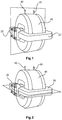
- Figure 1 shows a schematic perspective three-dimensional projection of a high voltage transformer according to an exemplary embodiment of the invention.
- Figure 1 shows a pulse transformer or high voltage transformer.
- Figure 1 defines a perpendicular cross section of a high voltage transformer with respect to its core according to an exemplary embodiment of the invention, which is shown in Figure 4 .
- Aluminum shells acting as field-control electrodes 22 may cover the magnetic cores of the high voltage transformer.
- the outer sleeve 40 encloses the inner sleeve and the high voltage winding.
- the high voltage wire pipes 45 guide the connections of the high voltage winding away from the field control electrodes 22 covering the magnetic cores.
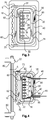
- Figure 2 shows a schematic perspective three-dimensional projection of a high voltage transformer according to a further exemplary embodiment of the invention.
- Figure 2 shows a pulse transformer or high voltage transformer.
- Figure 2 defines a parallel cross section of a high voltage transformer with respect to its core according to an exemplary embodiment of the invention, which is shown in Figure 3 .
- Aluminum shells acting as field-control electrodes 22 may cover the magnetic cores of the high voltage transformer.
- the outer sleeve 40 encloses the inner sleeve and the high voltage winding.
- the high voltage wire pipes 45 guide the connections of the high voltage winding away from the field control electrodes 22 covering the magnetic cores.
- Figure 3 shows a schematic cross section parallel to the core of a high voltage transformer according to an exemplary embodiment of the invention.
- FIG. 3 shows the attachment of the bobbin of the high voltage winding to the inner sleeve and of the inner sleeve to the outer sleeve, in a parallel two dimensional cross section. For simplification, only one half of the high voltage transformer is shown.
- the high voltage transformer comprises: a magnetic core 5, a low voltage winding 10, a high voltage winding 20, at least one inner sleeve 30, and a coil bobbin 24 for carrying the high voltage winding 20.
- the magnetic core 5 is made of a soft magnetic material, e.g. ferromagnetic material and/or ferrimagnetic material.
- the magnetic core 5 may comprise iron or nickel or alloys of iron or nickel or ceramic oxides of metals.
- the inner sleeve 30 may be fabricated from a plastic material or any other non-conductive synthetic or semi-synthetic solid material.
- the winding wire of the low voltage winding 10 and/or of the high voltage winding 20 is made of copper or a copper alloy or of aluminum or of an aluminum alloy, and the winding wire may coated with a very thin layer of insulation.
- the coil bobbin 24 may be divided into multiple slots 26, so that the voltage difference within each slot becomes only a fraction of that between the terminals of the high voltage winding.
- Thin insulation slots 28 between winding slots avoid discharges going over the bobbin surface. These insulation slots may also be used to return the winding wire from the top of one slot to the bottom of the next slot.
- the coil bobbin 24 is configured to be arranged inside the at least one inner sleeve 30 and is configured to be attached to the at least one inner sleeve 30 at an outer perimeter of the at least one inner sleeve 30.
- the coil bobbin 24 may be fabricated from a plastic material or any other non-conductive synthetic or semi-synthetic solid material.
- the coil bobbin 24 comprises at least one field-control electrode 22, which is adapted to shape an electric field generated by the high voltage winding 20.
- the magnetic core 5 may be a soft magnetic core.
- the high voltage transformer further comprises at least one outer sleeve 40.
- the high voltage transformer may further comprise an attachment 35 of the at least one inner sleeve 30 to the at least one outer sleeve 40 and attachment or flange 36 of high voltage winding 20 to the at least one inner sleeve 30.
- the high voltage transformer may further comprise at least one insulating high voltage wire pipe 45.
- the high voltage wire pipe 45 may be fabricated from a plastic material or any other non-conductive synthetic or semi-synthetic solid material.
- the high voltage transformer may further be fabricated by applying a press-fixture to the high voltage transformer assembly.
- the high voltage transformer 50 may further comprise further at least two labyrinth seals 60, which are placed opposite to each other.
- the labyrinth seals 60 may be fabricated as structures in an upper half and in a lower half of the inner sleeve 30 or as structures in an upper half and in a lower half of the outer sleeve 40.
- the outer sleeve 40 may be fabricated from a plastic material or any other non-conductive synthetic or semi-synthetic solid material.
- the high voltage transformer 50 may further comprise at least two insulating spring washers 70 for retaining the high voltage winding 20.
- the insulating spring washers 70 may be fabricated from a plastic material or any other non-conductive synthetic or semi-synthetic solid material.
- Figure 4 shows a schematic cross section perpendicular to the core of a high voltage transformer according to an exemplary embodiment of the invention.
- Figure 4 shows the attachment of the bobbin of the high voltage winding to the inner sleeve and of the inner sleeve to the outer sleeve in the perpendicular two dimensional cross section. For simplification, only one half of the high voltage transformer is shown.
- Figure 5 shows an X-ray system according to an exemplary embodiment of the invention.
- An X-ray system 100 may comprise an X-ray tube 110 and a high voltage transformer 50 which is configured to supply the X-ray tube 110.
- a high voltage test system 200 may comprise a high voltage transformer 50 which is configured to supply high voltage consumer 210.
- Figure 6 shows a schematic perspective three-dimensional projection of a high voltage transformer according to a further exemplary embodiment of the invention.
- the high voltage transformer as shown in Figure 6 comprises field-control electrodes 22 on core edges 80, aluminum shells covering the magnetic core 5, wherein the field-control electrodes 22 are arranged on the core edges 80.
Landscapes
- Engineering & Computer Science (AREA)
- Power Engineering (AREA)
- X-Ray Techniques (AREA)
- Insulating Of Coils (AREA)
Priority Applications (1)
| Application Number | Priority Date | Filing Date | Title |
|---|---|---|---|
| EP14812213.8A EP3084782B1 (en) | 2013-12-19 | 2014-12-11 | High voltage transformer comprising a coil bobbin for carrying a high voltage winding |
Applications Claiming Priority (3)
| Application Number | Priority Date | Filing Date | Title |
|---|---|---|---|
| EP13198581 | 2013-12-19 | ||
| EP14812213.8A EP3084782B1 (en) | 2013-12-19 | 2014-12-11 | High voltage transformer comprising a coil bobbin for carrying a high voltage winding |
| PCT/EP2014/077373 WO2015091202A1 (en) | 2013-12-19 | 2014-12-11 | High voltage transformer comprising a coil bobbin for carrying a high voltage winding |
Publications (2)
| Publication Number | Publication Date |
|---|---|
| EP3084782A1 EP3084782A1 (en) | 2016-10-26 |
| EP3084782B1 true EP3084782B1 (en) | 2019-05-22 |
Family
ID=49880480
Family Applications (1)
| Application Number | Title | Priority Date | Filing Date |
|---|---|---|---|
| EP14812213.8A Active EP3084782B1 (en) | 2013-12-19 | 2014-12-11 | High voltage transformer comprising a coil bobbin for carrying a high voltage winding |
Country Status (5)
| Country | Link |
|---|---|
| US (1) | US10090097B2 (enExample) |
| EP (1) | EP3084782B1 (enExample) |
| JP (1) | JP6400710B2 (enExample) |
| CN (1) | CN105940471A (enExample) |
| WO (1) | WO2015091202A1 (enExample) |
Cited By (1)
| Publication number | Priority date | Publication date | Assignee | Title |
|---|---|---|---|---|
| DE102022214442A1 (de) * | 2022-12-29 | 2024-07-04 | Siemens Healthineers Ag | Röntgengenerator und Röntgenvorrichtung |
Families Citing this family (2)
| Publication number | Priority date | Publication date | Assignee | Title |
|---|---|---|---|---|
| CN114600215A (zh) * | 2019-10-30 | 2022-06-07 | 三菱电机株式会社 | 螺线管装置以及起动器 |
| CN111799073B (zh) * | 2020-07-22 | 2023-05-12 | 中南大学 | 一种大功率高频变压器高压绕组骨架 |
Family Cites Families (13)
| Publication number | Priority date | Publication date | Assignee | Title |
|---|---|---|---|---|
| GB709361A (en) * | 1951-10-09 | 1954-05-19 | Moser Glaser & Co Ag | Improvements relating to high-voltage electric transformers |
| US4514712A (en) | 1975-02-13 | 1985-04-30 | Mcdougal John A | Ignition coil |
| JPS622738Y2 (enExample) * | 1980-05-20 | 1987-01-22 | ||
| DE3605629A1 (de) * | 1986-02-21 | 1987-09-03 | Koch & Sterzel Kg | Hochspannungstransformator |
| DE4021585A1 (de) * | 1990-07-06 | 1992-01-09 | Philips Patentverwaltung | Hochspannungstransformator, insbesondere fuer ein roentgengeraet |
| DE4204092C2 (de) * | 1992-02-12 | 1993-12-16 | Ant Nachrichtentech | Aus mindestens einer Wicklungskammer bestehender Spulenkörper für elektrisches Wickelgut, insbesondere für einen Hochspannungstransformator, sowie Hochspannungstransformator |
| US5847518A (en) * | 1996-07-08 | 1998-12-08 | Hitachi Ferrite Electronics, Ltd. | High voltage transformer with secondary coil windings on opposing bobbins |
| JPH118140A (ja) * | 1997-06-16 | 1999-01-12 | Ngk Spark Plug Co Ltd | 高圧トランス |
| TW369654B (en) * | 1997-07-07 | 1999-09-11 | Thomson Brandt Gmbh | Diode-split high-voltage transformer |
| JP2000357617A (ja) * | 1999-06-15 | 2000-12-26 | Matsushita Electric Ind Co Ltd | マグネトロン駆動用電源のトランス |
| DE102004033280A1 (de) * | 2004-07-09 | 2006-02-02 | Robert Bosch Gmbh | Einspritzventil zur Kraftstoffeinspritzung |
| JP2006237420A (ja) | 2005-02-28 | 2006-09-07 | Hitachi Media Electoronics Co Ltd | 変圧器及び電源装置 |
| JP5936620B2 (ja) | 2010-12-15 | 2016-06-22 | コーニンクレッカ フィリップス エヌ ヴェKoninklijke Philips N.V. | X線管用電源ユニット |
-
2014
- 2014-12-11 CN CN201480069574.2A patent/CN105940471A/zh active Pending
- 2014-12-11 JP JP2016539948A patent/JP6400710B2/ja not_active Expired - Fee Related
- 2014-12-11 WO PCT/EP2014/077373 patent/WO2015091202A1/en not_active Ceased
- 2014-12-11 EP EP14812213.8A patent/EP3084782B1/en active Active
- 2014-12-11 US US15/105,603 patent/US10090097B2/en active Active
Non-Patent Citations (1)
| Title |
|---|
| None * |
Cited By (2)
| Publication number | Priority date | Publication date | Assignee | Title |
|---|---|---|---|---|
| DE102022214442A1 (de) * | 2022-12-29 | 2024-07-04 | Siemens Healthineers Ag | Röntgengenerator und Röntgenvorrichtung |
| US12484136B2 (en) | 2022-12-29 | 2025-11-25 | Siemens Healthineers Ag | X-ray generator and X-ray apparatus |
Also Published As
| Publication number | Publication date |
|---|---|
| JP2017508274A (ja) | 2017-03-23 |
| JP6400710B2 (ja) | 2018-10-03 |
| WO2015091202A1 (en) | 2015-06-25 |
| EP3084782A1 (en) | 2016-10-26 |
| US10090097B2 (en) | 2018-10-02 |
| CN105940471A (zh) | 2016-09-14 |
| US20160314898A1 (en) | 2016-10-27 |
Similar Documents
| Publication | Publication Date | Title |
|---|---|---|
| US8928449B2 (en) | AC/DC planar transformer | |
| EP3109873B1 (en) | Inductor coil and electromagnetic component | |
| EP3084782B1 (en) | High voltage transformer comprising a coil bobbin for carrying a high voltage winding | |
| JP2012147670A5 (enExample) | ||
| JP2016018882A (ja) | 磁気回路部品 | |
| CN108257772A (zh) | 具有用于降低共模噪声的屏蔽层的变压器 | |
| US10361024B2 (en) | Dry-type transformer core | |
| KR101229631B1 (ko) | 표류 부하손을 절감하는 자기차폐형 변압기 | |
| EP2400513A1 (en) | Magnetic shielding for transformers | |
| US20230335333A1 (en) | Coil and a Transformer That Have Improved Electromagnetic Shielding | |
| EP2998971A1 (en) | Inductance device, filter device and corresponding power converter comprising the same | |
| US2901714A (en) | Transformer | |
| US20120274328A1 (en) | Axial high voltage transformer with signal pass-through ability | |
| RU155328U1 (ru) | Импульсный нейтронный генератор | |
| EP3497706B1 (en) | Inductor for high frequency and high power applications | |
| RU174178U1 (ru) | Импульсный нейтронный генератор | |
| JP2019510371A (ja) | 電磁誘導装置及びその製造方法 | |
| US8344843B2 (en) | Flux transfer device | |
| WO2015114623A1 (en) | An induction heating device | |
| Hataya et al. | Novel thin heating coil structure with reduced copper loss for high frequency induction cookers | |
| JP6692502B1 (ja) | 静止誘導機器 | |
| CN207572233U (zh) | 一种空芯电感屏蔽装置 | |
| CN203733555U (zh) | 高频电源用变压器 | |
| CN104715889A (zh) | 高频电源用变压器 | |
| WO2016071123A1 (en) | Resonant converter |
Legal Events
| Date | Code | Title | Description |
|---|---|---|---|
| PUAI | Public reference made under article 153(3) epc to a published international application that has entered the european phase |
Free format text: ORIGINAL CODE: 0009012 |
|
| 17P | Request for examination filed |
Effective date: 20160601 |
|
| AK | Designated contracting states |
Kind code of ref document: A1 Designated state(s): AL AT BE BG CH CY CZ DE DK EE ES FI FR GB GR HR HU IE IS IT LI LT LU LV MC MK MT NL NO PL PT RO RS SE SI SK SM TR |
|
| AX | Request for extension of the european patent |
Extension state: BA ME |
|
| DAX | Request for extension of the european patent (deleted) | ||
| GRAP | Despatch of communication of intention to grant a patent |
Free format text: ORIGINAL CODE: EPIDOSNIGR1 |
|
| STAA | Information on the status of an ep patent application or granted ep patent |
Free format text: STATUS: GRANT OF PATENT IS INTENDED |
|
| INTG | Intention to grant announced |
Effective date: 20181211 |
|
| GRAS | Grant fee paid |
Free format text: ORIGINAL CODE: EPIDOSNIGR3 |
|
| GRAA | (expected) grant |
Free format text: ORIGINAL CODE: 0009210 |
|
| STAA | Information on the status of an ep patent application or granted ep patent |
Free format text: STATUS: THE PATENT HAS BEEN GRANTED |
|
| AK | Designated contracting states |
Kind code of ref document: B1 Designated state(s): AL AT BE BG CH CY CZ DE DK EE ES FI FR GB GR HR HU IE IS IT LI LT LU LV MC MK MT NL NO PL PT RO RS SE SI SK SM TR |
|
| REG | Reference to a national code |
Ref country code: GB Ref legal event code: FG4D |
|
| REG | Reference to a national code |
Ref country code: CH Ref legal event code: EP |
|
| REG | Reference to a national code |
Ref country code: IE Ref legal event code: FG4D |
|
| REG | Reference to a national code |
Ref country code: AT Ref legal event code: REF Ref document number: 1137083 Country of ref document: AT Kind code of ref document: T Effective date: 20190615 |
|
| REG | Reference to a national code |
Ref country code: DE Ref legal event code: R096 Ref document number: 602014047338 Country of ref document: DE |
|
| REG | Reference to a national code |
Ref country code: NL Ref legal event code: MP Effective date: 20190522 |
|
| REG | Reference to a national code |
Ref country code: LT Ref legal event code: MG4D |
|
| PG25 | Lapsed in a contracting state [announced via postgrant information from national office to epo] |
Ref country code: AL Free format text: LAPSE BECAUSE OF FAILURE TO SUBMIT A TRANSLATION OF THE DESCRIPTION OR TO PAY THE FEE WITHIN THE PRESCRIBED TIME-LIMIT Effective date: 20190522 Ref country code: PT Free format text: LAPSE BECAUSE OF FAILURE TO SUBMIT A TRANSLATION OF THE DESCRIPTION OR TO PAY THE FEE WITHIN THE PRESCRIBED TIME-LIMIT Effective date: 20190922 Ref country code: FI Free format text: LAPSE BECAUSE OF FAILURE TO SUBMIT A TRANSLATION OF THE DESCRIPTION OR TO PAY THE FEE WITHIN THE PRESCRIBED TIME-LIMIT Effective date: 20190522 Ref country code: LT Free format text: LAPSE BECAUSE OF FAILURE TO SUBMIT A TRANSLATION OF THE DESCRIPTION OR TO PAY THE FEE WITHIN THE PRESCRIBED TIME-LIMIT Effective date: 20190522 Ref country code: HR Free format text: LAPSE BECAUSE OF FAILURE TO SUBMIT A TRANSLATION OF THE DESCRIPTION OR TO PAY THE FEE WITHIN THE PRESCRIBED TIME-LIMIT Effective date: 20190522 Ref country code: NL Free format text: LAPSE BECAUSE OF FAILURE TO SUBMIT A TRANSLATION OF THE DESCRIPTION OR TO PAY THE FEE WITHIN THE PRESCRIBED TIME-LIMIT Effective date: 20190522 Ref country code: NO Free format text: LAPSE BECAUSE OF FAILURE TO SUBMIT A TRANSLATION OF THE DESCRIPTION OR TO PAY THE FEE WITHIN THE PRESCRIBED TIME-LIMIT Effective date: 20190822 Ref country code: SE Free format text: LAPSE BECAUSE OF FAILURE TO SUBMIT A TRANSLATION OF THE DESCRIPTION OR TO PAY THE FEE WITHIN THE PRESCRIBED TIME-LIMIT Effective date: 20190522 Ref country code: ES Free format text: LAPSE BECAUSE OF FAILURE TO SUBMIT A TRANSLATION OF THE DESCRIPTION OR TO PAY THE FEE WITHIN THE PRESCRIBED TIME-LIMIT Effective date: 20190522 |
|
| PG25 | Lapsed in a contracting state [announced via postgrant information from national office to epo] |
Ref country code: LV Free format text: LAPSE BECAUSE OF FAILURE TO SUBMIT A TRANSLATION OF THE DESCRIPTION OR TO PAY THE FEE WITHIN THE PRESCRIBED TIME-LIMIT Effective date: 20190522 Ref country code: RS Free format text: LAPSE BECAUSE OF FAILURE TO SUBMIT A TRANSLATION OF THE DESCRIPTION OR TO PAY THE FEE WITHIN THE PRESCRIBED TIME-LIMIT Effective date: 20190522 Ref country code: BG Free format text: LAPSE BECAUSE OF FAILURE TO SUBMIT A TRANSLATION OF THE DESCRIPTION OR TO PAY THE FEE WITHIN THE PRESCRIBED TIME-LIMIT Effective date: 20190822 Ref country code: GR Free format text: LAPSE BECAUSE OF FAILURE TO SUBMIT A TRANSLATION OF THE DESCRIPTION OR TO PAY THE FEE WITHIN THE PRESCRIBED TIME-LIMIT Effective date: 20190823 |
|
| REG | Reference to a national code |
Ref country code: AT Ref legal event code: MK05 Ref document number: 1137083 Country of ref document: AT Kind code of ref document: T Effective date: 20190522 |
|
| PG25 | Lapsed in a contracting state [announced via postgrant information from national office to epo] |
Ref country code: CZ Free format text: LAPSE BECAUSE OF FAILURE TO SUBMIT A TRANSLATION OF THE DESCRIPTION OR TO PAY THE FEE WITHIN THE PRESCRIBED TIME-LIMIT Effective date: 20190522 Ref country code: RO Free format text: LAPSE BECAUSE OF FAILURE TO SUBMIT A TRANSLATION OF THE DESCRIPTION OR TO PAY THE FEE WITHIN THE PRESCRIBED TIME-LIMIT Effective date: 20190522 Ref country code: AT Free format text: LAPSE BECAUSE OF FAILURE TO SUBMIT A TRANSLATION OF THE DESCRIPTION OR TO PAY THE FEE WITHIN THE PRESCRIBED TIME-LIMIT Effective date: 20190522 Ref country code: EE Free format text: LAPSE BECAUSE OF FAILURE TO SUBMIT A TRANSLATION OF THE DESCRIPTION OR TO PAY THE FEE WITHIN THE PRESCRIBED TIME-LIMIT Effective date: 20190522 Ref country code: DK Free format text: LAPSE BECAUSE OF FAILURE TO SUBMIT A TRANSLATION OF THE DESCRIPTION OR TO PAY THE FEE WITHIN THE PRESCRIBED TIME-LIMIT Effective date: 20190522 Ref country code: SK Free format text: LAPSE BECAUSE OF FAILURE TO SUBMIT A TRANSLATION OF THE DESCRIPTION OR TO PAY THE FEE WITHIN THE PRESCRIBED TIME-LIMIT Effective date: 20190522 |
|
| REG | Reference to a national code |
Ref country code: DE Ref legal event code: R097 Ref document number: 602014047338 Country of ref document: DE |
|
| PG25 | Lapsed in a contracting state [announced via postgrant information from national office to epo] |
Ref country code: IT Free format text: LAPSE BECAUSE OF FAILURE TO SUBMIT A TRANSLATION OF THE DESCRIPTION OR TO PAY THE FEE WITHIN THE PRESCRIBED TIME-LIMIT Effective date: 20190522 Ref country code: SM Free format text: LAPSE BECAUSE OF FAILURE TO SUBMIT A TRANSLATION OF THE DESCRIPTION OR TO PAY THE FEE WITHIN THE PRESCRIBED TIME-LIMIT Effective date: 20190522 |
|
| RAP2 | Party data changed (patent owner data changed or rights of a patent transferred) |
Owner name: KONINKLIJKE PHILIPS N.V. |
|
| PLBE | No opposition filed within time limit |
Free format text: ORIGINAL CODE: 0009261 |
|
| STAA | Information on the status of an ep patent application or granted ep patent |
Free format text: STATUS: NO OPPOSITION FILED WITHIN TIME LIMIT |
|
| PG25 | Lapsed in a contracting state [announced via postgrant information from national office to epo] |
Ref country code: TR Free format text: LAPSE BECAUSE OF FAILURE TO SUBMIT A TRANSLATION OF THE DESCRIPTION OR TO PAY THE FEE WITHIN THE PRESCRIBED TIME-LIMIT Effective date: 20190522 |
|
| 26N | No opposition filed |
Effective date: 20200225 |
|
| PG25 | Lapsed in a contracting state [announced via postgrant information from national office to epo] |
Ref country code: PL Free format text: LAPSE BECAUSE OF FAILURE TO SUBMIT A TRANSLATION OF THE DESCRIPTION OR TO PAY THE FEE WITHIN THE PRESCRIBED TIME-LIMIT Effective date: 20190522 |
|
| PG25 | Lapsed in a contracting state [announced via postgrant information from national office to epo] |
Ref country code: SI Free format text: LAPSE BECAUSE OF FAILURE TO SUBMIT A TRANSLATION OF THE DESCRIPTION OR TO PAY THE FEE WITHIN THE PRESCRIBED TIME-LIMIT Effective date: 20190522 |
|
| REG | Reference to a national code |
Ref country code: CH Ref legal event code: PL |
|
| REG | Reference to a national code |
Ref country code: BE Ref legal event code: MM Effective date: 20191231 |
|
| PG25 | Lapsed in a contracting state [announced via postgrant information from national office to epo] |
Ref country code: MC Free format text: LAPSE BECAUSE OF FAILURE TO SUBMIT A TRANSLATION OF THE DESCRIPTION OR TO PAY THE FEE WITHIN THE PRESCRIBED TIME-LIMIT Effective date: 20190522 |
|
| GBPC | Gb: european patent ceased through non-payment of renewal fee |
Effective date: 20191211 |
|
| PG25 | Lapsed in a contracting state [announced via postgrant information from national office to epo] |
Ref country code: LU Free format text: LAPSE BECAUSE OF NON-PAYMENT OF DUE FEES Effective date: 20191211 Ref country code: IE Free format text: LAPSE BECAUSE OF NON-PAYMENT OF DUE FEES Effective date: 20191211 Ref country code: GB Free format text: LAPSE BECAUSE OF NON-PAYMENT OF DUE FEES Effective date: 20191211 Ref country code: FR Free format text: LAPSE BECAUSE OF NON-PAYMENT OF DUE FEES Effective date: 20191231 |
|
| PG25 | Lapsed in a contracting state [announced via postgrant information from national office to epo] |
Ref country code: BE Free format text: LAPSE BECAUSE OF NON-PAYMENT OF DUE FEES Effective date: 20191231 Ref country code: LI Free format text: LAPSE BECAUSE OF NON-PAYMENT OF DUE FEES Effective date: 20191231 Ref country code: CH Free format text: LAPSE BECAUSE OF NON-PAYMENT OF DUE FEES Effective date: 20191231 |
|
| PG25 | Lapsed in a contracting state [announced via postgrant information from national office to epo] |
Ref country code: CY Free format text: LAPSE BECAUSE OF FAILURE TO SUBMIT A TRANSLATION OF THE DESCRIPTION OR TO PAY THE FEE WITHIN THE PRESCRIBED TIME-LIMIT Effective date: 20190522 |
|
| PG25 | Lapsed in a contracting state [announced via postgrant information from national office to epo] |
Ref country code: IS Free format text: LAPSE BECAUSE OF FAILURE TO SUBMIT A TRANSLATION OF THE DESCRIPTION OR TO PAY THE FEE WITHIN THE PRESCRIBED TIME-LIMIT Effective date: 20190922 |
|
| PG25 | Lapsed in a contracting state [announced via postgrant information from national office to epo] |
Ref country code: MT Free format text: LAPSE BECAUSE OF FAILURE TO SUBMIT A TRANSLATION OF THE DESCRIPTION OR TO PAY THE FEE WITHIN THE PRESCRIBED TIME-LIMIT Effective date: 20190522 Ref country code: HU Free format text: LAPSE BECAUSE OF FAILURE TO SUBMIT A TRANSLATION OF THE DESCRIPTION OR TO PAY THE FEE WITHIN THE PRESCRIBED TIME-LIMIT; INVALID AB INITIO Effective date: 20141211 |
|
| PG25 | Lapsed in a contracting state [announced via postgrant information from national office to epo] |
Ref country code: MK Free format text: LAPSE BECAUSE OF FAILURE TO SUBMIT A TRANSLATION OF THE DESCRIPTION OR TO PAY THE FEE WITHIN THE PRESCRIBED TIME-LIMIT Effective date: 20190522 |
|
| REG | Reference to a national code |
Ref country code: DE Ref legal event code: R084 Ref document number: 602014047338 Country of ref document: DE |
|
| PGFP | Annual fee paid to national office [announced via postgrant information from national office to epo] |
Ref country code: DE Payment date: 20241227 Year of fee payment: 11 |