EP3084751B1 - Peripheral vision hover drift cueing - Google Patents
Peripheral vision hover drift cueing Download PDFInfo
- Publication number
- EP3084751B1 EP3084751B1 EP14883087.0A EP14883087A EP3084751B1 EP 3084751 B1 EP3084751 B1 EP 3084751B1 EP 14883087 A EP14883087 A EP 14883087A EP 3084751 B1 EP3084751 B1 EP 3084751B1
- Authority
- EP
- European Patent Office
- Prior art keywords
- drift
- vehicle
- peripheral vision
- indicator
- hover
- Prior art date
- Legal status (The legal status is an assumption and is not a legal conclusion. Google has not performed a legal analysis and makes no representation as to the accuracy of the status listed.)
- Not-in-force
Links
- 230000005043 peripheral vision Effects 0.000 title claims description 54
- 238000000034 method Methods 0.000 claims description 19
- 238000004590 computer program Methods 0.000 claims description 3
- 230000004044 response Effects 0.000 claims description 2
- 238000010586 diagram Methods 0.000 description 6
- 230000000007 visual effect Effects 0.000 description 5
- 238000003384 imaging method Methods 0.000 description 3
- 210000000873 fovea centralis Anatomy 0.000 description 2
- 241000566150 Pandion haliaetus Species 0.000 description 1
- 210000004556 brain Anatomy 0.000 description 1
- 238000013500 data storage Methods 0.000 description 1
- 206010013395 disorientation Diseases 0.000 description 1
- 239000000428 dust Substances 0.000 description 1
- 230000004438 eyesight Effects 0.000 description 1
- 239000000463 material Substances 0.000 description 1
- 230000003340 mental effect Effects 0.000 description 1
- 230000003287 optical effect Effects 0.000 description 1
- 210000001525 retina Anatomy 0.000 description 1
- 238000012552 review Methods 0.000 description 1
- 239000004576 sand Substances 0.000 description 1
- 230000035807 sensation Effects 0.000 description 1
- -1 snow Substances 0.000 description 1
- 238000012876 topography Methods 0.000 description 1
- 210000000857 visual cortex Anatomy 0.000 description 1
Images


Classifications
-
- G—PHYSICS
- G06—COMPUTING; CALCULATING OR COUNTING
- G06F—ELECTRIC DIGITAL DATA PROCESSING
- G06F3/00—Input arrangements for transferring data to be processed into a form capable of being handled by the computer; Output arrangements for transferring data from processing unit to output unit, e.g. interface arrangements
- G06F3/14—Digital output to display device ; Cooperation and interconnection of the display device with other functional units
-
- B—PERFORMING OPERATIONS; TRANSPORTING
- B64—AIRCRAFT; AVIATION; COSMONAUTICS
- B64D—EQUIPMENT FOR FITTING IN OR TO AIRCRAFT; FLIGHT SUITS; PARACHUTES; ARRANGEMENTS OR MOUNTING OF POWER PLANTS OR PROPULSION TRANSMISSIONS IN AIRCRAFT
- B64D43/00—Arrangements or adaptations of instruments
-
- B—PERFORMING OPERATIONS; TRANSPORTING
- B64—AIRCRAFT; AVIATION; COSMONAUTICS
- B64D—EQUIPMENT FOR FITTING IN OR TO AIRCRAFT; FLIGHT SUITS; PARACHUTES; ARRANGEMENTS OR MOUNTING OF POWER PLANTS OR PROPULSION TRANSMISSIONS IN AIRCRAFT
- B64D45/00—Aircraft indicators or protectors not otherwise provided for
-
- B—PERFORMING OPERATIONS; TRANSPORTING
- B63—SHIPS OR OTHER WATERBORNE VESSELS; RELATED EQUIPMENT
- B63B—SHIPS OR OTHER WATERBORNE VESSELS; EQUIPMENT FOR SHIPPING
- B63B49/00—Arrangements of nautical instruments or navigational aids
-
- B—PERFORMING OPERATIONS; TRANSPORTING
- B64—AIRCRAFT; AVIATION; COSMONAUTICS
- B64D—EQUIPMENT FOR FITTING IN OR TO AIRCRAFT; FLIGHT SUITS; PARACHUTES; ARRANGEMENTS OR MOUNTING OF POWER PLANTS OR PROPULSION TRANSMISSIONS IN AIRCRAFT
- B64D45/00—Aircraft indicators or protectors not otherwise provided for
- B64D45/04—Landing aids; Safety measures to prevent collision with earth's surface
-
- G—PHYSICS
- G01—MEASURING; TESTING
- G01C—MEASURING DISTANCES, LEVELS OR BEARINGS; SURVEYING; NAVIGATION; GYROSCOPIC INSTRUMENTS; PHOTOGRAMMETRY OR VIDEOGRAMMETRY
- G01C21/00—Navigation; Navigational instruments not provided for in groups G01C1/00 - G01C19/00
- G01C21/26—Navigation; Navigational instruments not provided for in groups G01C1/00 - G01C19/00 specially adapted for navigation in a road network
- G01C21/34—Route searching; Route guidance
- G01C21/36—Input/output arrangements for on-board computers
- G01C21/3626—Details of the output of route guidance instructions
- G01C21/3629—Guidance using speech or audio output, e.g. text-to-speech
-
- G—PHYSICS
- G01—MEASURING; TESTING
- G01C—MEASURING DISTANCES, LEVELS OR BEARINGS; SURVEYING; NAVIGATION; GYROSCOPIC INSTRUMENTS; PHOTOGRAMMETRY OR VIDEOGRAMMETRY
- G01C21/00—Navigation; Navigational instruments not provided for in groups G01C1/00 - G01C19/00
- G01C21/26—Navigation; Navigational instruments not provided for in groups G01C1/00 - G01C19/00 specially adapted for navigation in a road network
- G01C21/34—Route searching; Route guidance
- G01C21/36—Input/output arrangements for on-board computers
- G01C21/3664—Details of the user input interface, e.g. buttons, knobs or sliders, including those provided on a touch screen; remote controllers; input using gestures
Definitions
- Some implementations relate generally to avionics and, more particularly, to methods, systems and computer readable media for peripheral vision hover drift cueing.
- Rotary wing aircraft and tilt rotor aircraft such as the V-22 Osprey are routinely required to approach and land at sites without navigation guidance and/or in limited visibility conditions. Often the topography, ground hazards, obstacles and weather in the area are unknown or changing. Upon arrival at a landing or hover site, the pilot typically makes critical judgments based on incomplete or inaccurate data in order to determine the proper procedure to approach and land. If the terrain condition is such that dust, snow, sand, or the like will be stirred by rotor downwash, the aircraft may become engulfed in a cloud of visually-restrictive material. This is commonly referred to as a degraded visual environment (DVE) or a "brownout/whiteout" situation.
- DVE degraded visual environment
- Spatial disorientation in a DVE is a common cause of incidents according to some literature reviews, pilot interviews, and military incident reports.
- the pilot may manipulate the aircraft controls to conduct a constant deceleration of longitudinal velocity while coordinating a rate of descent to the ground (or hover point) in such a way as to arrive with little or no forward velocity and a low rate of descent.
- the pilot In addition to controlling a rate of descent, the pilot must also typically compensate for forward, aft, lateral, and heading drift.
- a pilot may be denied both his peripheral vision cues and relative speed and drift sensations provided by his/her subconscious vision channels.
- Some conventional instrument flight displays may require a pilot to use the central portion of his/her visual known as the fovea centralis.
- the fovea centralis occupies a small portion of the central field of view (e.g., 1% of the visual area of the retina), but may use 50% of the visual cortex in the brain.
- critical hover drift information to this area of a pilot's visual field, a mental processing bandwidth constraint is created in highly task loaded environments.
- Document US 2009002220 discloses an imaging system for a rotary aircraft having a millimeter wave imager with visible or infrared overlay.
- the system includes an active millimeter wave imaging system comprising a millimeter wave transmitter and a millimeter wave phased array receiver for producing millimeter wave images of a landing region, a second imaging system operating at visible or infrared wavelengths to produce visible or infrared images of the landing region, and a processor programmed with a see and remember algorithm for overlaying the visible or infrared images and the millimeter wave images and to save at least one good high-resolution visible or infrared image in case of a brownout event begins to obscuring the visible or infrared images wherein in case of the brownout event the millimeter wave images are overlaid on the at least one good visible or infrared image and not obscured visible or infrared images.
- Document US 2003/0127557 A1 discloses a visual indication system which extends on a side of an aircraft windshield.
- the invention discloses a system comprising one or more sensors and a peripheral vision hover drift cueing controller coupled to the one or more sensors and configured to determine hover drift and to control a plurality of indicators in response to determined hover drift.
- the sensors/information sources can include one or more of a radar altimeter, an air data system, an inertial navigation system, a traffic alert and collision avoidance system, an Enhanced Ground Proximity Warning System (EGPWS)/Controlled Flight Into Terrain (CFIT) system, a digital map, a terrain database, a Global Positioning System (GPS) receiver, a Differential Global Positioning System (DGPS) receiver, a microwave radar, a forward looking infrared (FLIR) camera, and/or a video camera.
- a radar altimeter an air data system
- an inertial navigation system a traffic alert and collision avoidance system
- an Enhanced Ground Proximity Warning System (EGPWS)/Controlled Flight Into Terrain (CFIT) system a digital map, a terrain database, a Global Positioning System (GPS) receiver, a Differential Global Positioning System (DGPS) receiver, a microwave radar, a forward looking infrared (FLIR) camera, and/or a video
- the system can include a third hover drift indicator coupled to the controller.
- the first hover drift indicator can be configured to indicate fore/aft drift.
- the second hover drift indicator can be configured to indicate lateral drift.
- the first hover drift indicator is mounted on a door frame of the aircraft adjacent a pilot's seat so as to be visible in a peripheral vision field of the pilot.
- the second hover drift indicator can be mounted adjacent to a central instrument panel of the aircraft so as to be visible in a peripheral vision field of the pilot.
- Some implementations can include a method.
- the method can include receiving, at a processor, aircraft position information from one or more sensors disposed on the aircraft.
- the method can also include determining, at the processor, hover drift based on the received aircraft position information.
- the method can further include controlling, with the processor, one or more peripheral vision hover drift indicators based on the determined hover drift.
- the one or more sensors can include one or more of a radar altimeter, an air data system, an inertial navigation system, a traffic alert and collision avoidance system, an Enhanced Ground Proximity Warning System (EGPWS)/Controlled Flight Into Terrain (CFIT) system, a digital map, a terrain database, a Global Positioning System (GPS) receiver, a Differential Global Positioning System (DGPS) receiver, a microwave radar, a forward looking infrared (FLIR) camera, and/or a video camera.
- a radar altimeter an air data system
- an inertial navigation system a traffic alert and collision avoidance system
- an Enhanced Ground Proximity Warning System (EGPWS)/Controlled Flight Into Terrain (CFIT) system a digital map, a terrain database
- GPS Global Positioning System
- DGPS Differential Global Positioning System
- microwave radar a forward looking infrared (FLIR) camera
- FLIR forward looking infrared
- the one or more peripheral vision hover drift indicators can include a first hover drift indicator and a second hover drift indicator.
- the one or more peripheral vision hover drift indicators can further comprise a third hover drift indicator coupled to the processor.
- the first hover drift indicator can be configured to indicate fore/aft drift.
- the second hover drift indicator can be configured to indicate lateral drift.
- the first hover drift indicator can be mounted on a door frame of the aircraft adjacent a pilot's seat so as to be visible in a peripheral vision field of the pilot.
- the second hover drift indicator can be mounted adjacent to a central instrument panel of the aircraft so as to be visible in a peripheral vision field of the pilot.
- Some implementations can include a nontransitory computer readable medium having stored thereon software instructions that, when executed, cause a processor to perform operations.
- the operations can include receiving, at a processor, aircraft position information from one or more sensors disposed on the aircraft.
- the operations can also include determining, at the processor, hover drift based on the received aircraft position information.
- the operations can further include controlling, with the processor, one or more peripheral vision hover drift indicators based on the determined hover drift.
- the one or more sensors can include one or more of a radar altimeter, an air data system, an inertial navigation system, a traffic alert and collision avoidance system, an Enhanced Ground Proximity Warning System (EGPWS)/Controlled Flight Into Terrain (CFIT) system, a digital map, a terrain database, a Global Positioning System (GPS) receiver, a Differential Global Positioning System (DGPS) receiver, a microwave radar, a forward looking infrared (FLIR) camera, and/or a video camera.
- a radar altimeter an air data system
- an inertial navigation system a traffic alert and collision avoidance system
- an Enhanced Ground Proximity Warning System (EGPWS)/Controlled Flight Into Terrain (CFIT) system a digital map, a terrain database
- GPS Global Positioning System
- DGPS Differential Global Positioning System
- microwave radar a forward looking infrared (FLIR) camera
- FLIR forward looking infrared
- the one or more peripheral vision hover drift indicators can include a first hover drift indicator and a second hover drift indicator.
- the first hover drift indicator can be configured to indicate fore/aft drift and can be mounted on a door frame of the aircraft adjacent a pilot's seat so as to be visible in a peripheral vision field of the pilot.
- the second hover drift indicator can be configured to indicate lateral drift and can be mounted adjacent to a central instrument panel of the aircraft so as to be visible in a peripheral vision field of the pilot.
- FIG. 1 shows a diagram of an example peripheral vision hover drift cueing system in accordance with some implementations.
- the system 100 includes one or more position information systems 102, a peripheral vision hover drift cueing system 104 (or controller), one or more fore/aft drift indicators 106, one or more lateral drift indicators 108 and, optionally, one or more other drift indicators 110 for a parameter such as heading, altitude or the like.
- the position sensor systems 102 generate position information, which is transmitted to the peripheral vision hover drift cueing system 104.
- the sensor systems 102 can include, for example, one or more of a radar altimeter, an air data system, an inertial navigation system, a traffic alert and collision avoidance system, an Enhanced Ground Proximity Warning System (EGPWS)/Controlled Flight Into Terrain (CFIT) system, a digital map, a terrain database, a Global Positioning System (GPS) receiver, a Differential Global Positioning System (DGPS) receiver, a microwave radar, a forward looking infrared (FLIR) camera, and/or a video camera.
- GPS Global Positioning System
- DGPS Differential Global Positioning System
- microwave radar a forward looking infrared (FLIR) camera
- FLIR forward looking infrared
- FLIR forward looking infrared
- the peripheral vision hover drift cueing system 104 uses the received position information to determine if the aircraft is drifting from hover. For example, the peripheral vision hover drift cueing system 104 can compare the position information received over time to determine if the aircraft is drifting in hover. Drifting from hover can occur in one or more directions and/or axes such as fore/aft, lateral, heading, altitude, yaw, pitch and/or roll.
- the peripheral vision hover drift cueing system 104 can cause a signal to be sent to one or more peripheral vision indicators, such as the fore/aft drift indicator(s) 106, the lateral drift indicators 108 and/or the other drift indicator(s) 110.
- peripheral vision indicators such as the fore/aft drift indicator(s) 106, the lateral drift indicators 108 and/or the other drift indicator(s) 110.
- the drift indicators include one or more light emitting diodes (LEDs).
- the indicator causes the LEDs to appear to be moving (e.g., in a direction of the drift). For example, if the aircraft is drifting in an aft direction, the fore/aft indicator is used to show this drift by causing the LEDs to appear to move in a direction that would suggest aft movement in the pilot's peripheral vision.
- the indicators can be placed within the cockpit in locations for viewing by the pilot's peripheral vision.
- the lateral drift indicator can be placed above or below the main instrument panel.
- the fore/aft indicator is placed on a door or doorframe of the aircraft to an outside side of a pilot's seat.
- An example placement of peripheral vision hover drift cueing indicators is shown in FIG. 3 and described below.
- the indicators can use color change, brightness change, flashing or the like to indicate drift and/or amount or rate of drift.
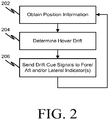
- FIG. 2 shows a flow chart of an example method for peripheral vision hover drift cueing in accordance with some implementations.
- Processing begins at 202, where position (or other) information is obtained.
- position information from one or more sensors e.g., 102
- the information can include flight information such as velocity, height above ground, groundspeed, ground track, wind direction, wind speed, location of a landing/hover zone, location of other aircraft, aircraft performance, or the like.
- Flight information such as velocity, height above ground, groundspeed, ground track, wind direction, wind speed, location of a landing/hover zone, location of other aircraft, aircraft performance, or the like.
- Processing continues to 204.
- the system determines if hover drift is occurring. For example, the system can compare current position information with previous position information. Processing continues to 206.
- the system sends a signal to each indicator (e.g., 106 - 110) according to the determined amount of drift. It will be appreciated that 202-206 can be repeated in whole or in part in order to accomplish a contemplated peripheral vision hover drift cueing task.
- FIG. 3 is a diagram of an example aircraft cockpit 300 having a peripheral vision hover drift cueing system in accordance with some implementations.
- the cockpit 300 includes a first fore/aft drift indicator 302 disposed on the port side door of the aircraft, a second fore/aft drift indicator 304 disposed on the starboard side door of the aircraft, a lateral drift indicator (306 or 308) disposed above or below the instrument panel 310.
- the indicators (302 - 308) can be controlled by a peripheral vision hover drift cueing system (e.g., 104) in accordance with a method or process for peripheral vision hover drift cueing (e.g., 202 - 206).
- a peripheral vision hover drift cueing system e.g., 104
- a method or process for peripheral vision hover drift cueing e.g., 202 - 206
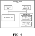
- FIG. 4 is a diagram of an example computing device for peripheral vision hover drift cueing in accordance with some implementations.
- the computing device 400 includes a processor 402, an operating system 404, a memory 406 and an I/O interface 408.
- the memory 406 can store a peripheral vision hover drift cueing application 410 and hover location, position and/or drift data 412.
- the processor 402 may execute the peripheral vision hover drift cueing application 410 stored in the memory 406.
- the peripheral vision hover drift cueing application 410 can include software instructions that, when executed by the processor 402, cause the processor 402 to perform operations for peripheral vision hover drift cueing in accordance with the present disclosure (e.g., the peripheral vision hover drift cueing application 410 can cause the processor to perform one or more of steps 202-206 described above and, in conjunction, can access the hover location, aircraft position and/or drift data 412).
- the peripheral vision hover drift cueing application 410 can also operate in conjunction with the operating system 404.
- the computer can include, but is not limited to, a single processor system, a multi-processor system (co-located or distributed), a cloud computing system, or a combination of the above.
- a network can connect the sensors, the peripheral vision hover drift cueing system and the indicators.
- the network can be a wired or wireless network, and can include, but is not limited to, an aircraft signal bus, a WiFi network, a local area network, a wide area network, the Internet, or a combination of the above.
- the data storage, memory and/or nontransitory computer readable medium can be a magnetic storage device (hard disk drive or the like), optical storage device (CD, DVD or the like), electronic storage device (RAM, ROM, flash, or the like).
- the software instructions can also be contained in, and provided as, an electronic signal, for example in the form of software as a service (SaaS) delivered from a server (e.g., a distributed system and/or a cloud computing system).
- SaaS software as a service
- some implementations of the disclosed method, system, and computer readable media can be implemented in software (e.g., as a computer program product and/or nontransitory computer readable media having stored instructions for performing one or more peripheral vision hover drift cueing tasks as described herein).
- the stored software instructions can be executed on a programmed general purpose computer, a special purpose computer, a microprocessor, or the like.
- the computing device 400 can be a standalone computing device or a device incorporated in another system, such as an avionics system or flight computer.
- the vehicle may be a rotary wing aircraft, a fixed wing aircraft, a vertical take off aircraft, or a ground vehicle.
- the vehicle may alternatively be a watercraft such as, for example, a surface ship, a submarine, or a hovercraft.
Description
- Some implementations relate generally to avionics and, more particularly, to methods, systems and computer readable media for peripheral vision hover drift cueing.
- Rotary wing aircraft (and tilt rotor aircraft such as the V-22 Osprey) are routinely required to approach and land at sites without navigation guidance and/or in limited visibility conditions. Often the topography, ground hazards, obstacles and weather in the area are unknown or changing. Upon arrival at a landing or hover site, the pilot typically makes critical judgments based on incomplete or inaccurate data in order to determine the proper procedure to approach and land. If the terrain condition is such that dust, snow, sand, or the like will be stirred by rotor downwash, the aircraft may become engulfed in a cloud of visually-restrictive material. This is commonly referred to as a degraded visual environment (DVE) or a "brownout/whiteout" situation.
- Spatial disorientation in a DVE is a common cause of incidents according to some literature reviews, pilot interviews, and military incident reports. During approach to hover and landing, the pilot may manipulate the aircraft controls to conduct a constant deceleration of longitudinal velocity while coordinating a rate of descent to the ground (or hover point) in such a way as to arrive with little or no forward velocity and a low rate of descent. In addition to controlling a rate of descent, the pilot must also typically compensate for forward, aft, lateral, and heading drift.
- In a DVE, such as instrument meteorological conditions (IMC) or brownout/whiteout situations, a pilot may be denied both his peripheral vision cues and relative speed and drift sensations provided by his/her subconscious vision channels. Some conventional instrument flight displays may require a pilot to use the central portion of his/her visual known as the fovea centralis. The fovea centralis occupies a small portion of the central field of view (e.g., 1% of the visual area of the retina), but may use 50% of the visual cortex in the brain. Thus, by presenting critical hover drift information to this area of a pilot's visual field, a mental processing bandwidth constraint is created in highly task loaded environments. Some implementations were conceived in light of the above-mentioned problems and limitations, among other things.
- Document
US 2009002220 discloses an imaging system for a rotary aircraft having a millimeter wave imager with visible or infrared overlay. The system includes an active millimeter wave imaging system comprising a millimeter wave transmitter and a millimeter wave phased array receiver for producing millimeter wave images of a landing region, a second imaging system operating at visible or infrared wavelengths to produce visible or infrared images of the landing region, and a processor programmed with a see and remember algorithm for overlaying the visible or infrared images and the millimeter wave images and to save at least one good high-resolution visible or infrared image in case of a brownout event begins to obscuring the visible or infrared images wherein in case of the brownout event the millimeter wave images are overlaid on the at least one good visible or infrared image and not obscured visible or infrared images. DocumentUS 2003/0127557 A1 discloses a visual indication system which extends on a side of an aircraft windshield. - The invention discloses a system comprising one or more sensors and a peripheral vision hover drift cueing controller coupled to the one or more sensors and configured to determine hover drift and to control a plurality of indicators in response to determined hover drift.
- The sensors/information sources can include one or more of a radar altimeter, an air data system, an inertial navigation system, a traffic alert and collision avoidance system, an Enhanced Ground Proximity Warning System (EGPWS)/Controlled Flight Into Terrain (CFIT) system, a digital map, a terrain database, a Global Positioning System (GPS) receiver, a Differential Global Positioning System (DGPS) receiver, a microwave radar, a forward looking infrared (FLIR) camera, and/or a video camera.
- The system can include a third hover drift indicator coupled to the controller. The first hover drift indicator can be configured to indicate fore/aft drift. The second hover drift indicator can be configured to indicate lateral drift. The first hover drift indicator is mounted on a door frame of the aircraft adjacent a pilot's seat so as to be visible in a peripheral vision field of the pilot. The second hover drift indicator can be mounted adjacent to a central instrument panel of the aircraft so as to be visible in a peripheral vision field of the pilot.
- Some implementations can include a method. The method can include receiving, at a processor, aircraft position information from one or more sensors disposed on the aircraft. The method can also include determining, at the processor, hover drift based on the received aircraft position information. The method can further include controlling, with the processor, one or more peripheral vision hover drift indicators based on the determined hover drift.
- The one or more sensors can include one or more of a radar altimeter, an air data system, an inertial navigation system, a traffic alert and collision avoidance system, an Enhanced Ground Proximity Warning System (EGPWS)/Controlled Flight Into Terrain (CFIT) system, a digital map, a terrain database, a Global Positioning System (GPS) receiver, a Differential Global Positioning System (DGPS) receiver, a microwave radar, a forward looking infrared (FLIR) camera, and/or a video camera.
- The one or more peripheral vision hover drift indicators can include a first hover drift indicator and a second hover drift indicator. The one or more peripheral vision hover drift indicators can further comprise a third hover drift indicator coupled to the processor.
- The first hover drift indicator can be configured to indicate fore/aft drift. The second hover drift indicator can be configured to indicate lateral drift. The first hover drift indicator can be mounted on a door frame of the aircraft adjacent a pilot's seat so as to be visible in a peripheral vision field of the pilot. The second hover drift indicator can be mounted adjacent to a central instrument panel of the aircraft so as to be visible in a peripheral vision field of the pilot.
- Some implementations can include a nontransitory computer readable medium having stored thereon software instructions that, when executed, cause a processor to perform operations. The operations can include receiving, at a processor, aircraft position information from one or more sensors disposed on the aircraft. The operations can also include determining, at the processor, hover drift based on the received aircraft position information. The operations can further include controlling, with the processor, one or more peripheral vision hover drift indicators based on the determined hover drift.
- The one or more sensors can include one or more of a radar altimeter, an air data system, an inertial navigation system, a traffic alert and collision avoidance system, an Enhanced Ground Proximity Warning System (EGPWS)/Controlled Flight Into Terrain (CFIT) system, a digital map, a terrain database, a Global Positioning System (GPS) receiver, a Differential Global Positioning System (DGPS) receiver, a microwave radar, a forward looking infrared (FLIR) camera, and/or a video camera.
- The one or more peripheral vision hover drift indicators can include a first hover drift indicator and a second hover drift indicator. The first hover drift indicator can be configured to indicate fore/aft drift and can be mounted on a door frame of the aircraft adjacent a pilot's seat so as to be visible in a peripheral vision field of the pilot. The second hover drift indicator can be configured to indicate lateral drift and can be mounted adjacent to a central instrument panel of the aircraft so as to be visible in a peripheral vision field of the pilot.
-
-
FIG. 1 shows a diagram of an example peripheral vision hover drift cueing system in accordance with some implementations. -
FIG. 2 shows a flow chart of an example method for peripheral vision hover drift cueing in accordance with some implementations. -
FIG. 3 is a diagram of an example aircraft cockpit having a peripheral vision hover drift cueing system in accordance with some implementations. -
FIG. 4 is a diagram of an example computing system for peripheral vision hover drift cueing in accordance with some implementations. -
FIG. 1 shows a diagram of an example peripheral vision hover drift cueing system in accordance with some implementations. Thesystem 100 includes one or moreposition information systems 102, a peripheral vision hover drift cueing system 104 (or controller), one or more fore/aft drift indicators 106, one or morelateral drift indicators 108 and, optionally, one or moreother drift indicators 110 for a parameter such as heading, altitude or the like. - In operation, the
position sensor systems 102 generate position information, which is transmitted to the peripheral vision hoverdrift cueing system 104. Thesensor systems 102 can include, for example, one or more of a radar altimeter, an air data system, an inertial navigation system, a traffic alert and collision avoidance system, an Enhanced Ground Proximity Warning System (EGPWS)/Controlled Flight Into Terrain (CFIT) system, a digital map, a terrain database, a Global Positioning System (GPS) receiver, a Differential Global Positioning System (DGPS) receiver, a microwave radar, a forward looking infrared (FLIR) camera, and/or a video camera. In addition to the above-mentioned example sensors, traditional avionics instruments (altimeter, vertical speed indicator, compass, air speed indicator or the like) could also be included in thesensor system 102. - The peripheral vision hover
drift cueing system 104 uses the received position information to determine if the aircraft is drifting from hover. For example, the peripheral vision hoverdrift cueing system 104 can compare the position information received over time to determine if the aircraft is drifting in hover. Drifting from hover can occur in one or more directions and/or axes such as fore/aft, lateral, heading, altitude, yaw, pitch and/or roll. - If the peripheral vision hover
drift cueing system 104 determines drift is occurring, the peripheral vision hoverdrift cueing system 104 can cause a signal to be sent to one or more peripheral vision indicators, such as the fore/aft drift indicator(s) 106, thelateral drift indicators 108 and/or the other drift indicator(s) 110. - The drift indicators (e.g., 106 - 110) include one or more light emitting diodes (LEDs). In order to provide a peripheral vision cue, the indicator causes the LEDs to appear to be moving (e.g., in a direction of the drift). For example, if the aircraft is drifting in an aft direction, the fore/aft indicator is used to show this drift by causing the LEDs to appear to move in a direction that would suggest aft movement in the pilot's peripheral vision.
- The indicators can be placed within the cockpit in locations for viewing by the pilot's peripheral vision. For example, the lateral drift indicator can be placed above or below the main instrument panel. The fore/aft indicator is placed on a door or doorframe of the aircraft to an outside side of a pilot's seat. An example placement of peripheral vision hover drift cueing indicators is shown in
FIG. 3 and described below. In addition to, or as an alternative to, using apparent motion, the indicators can use color change, brightness change, flashing or the like to indicate drift and/or amount or rate of drift. -
FIG. 2 shows a flow chart of an example method for peripheral vision hover drift cueing in accordance with some implementations. Processing begins at 202, where position (or other) information is obtained. For example, position information from one or more sensors (e.g., 102) can be obtained by a peripheral vision hover drift cueing system (e.g., 104). The information can include flight information such as velocity, height above ground, groundspeed, ground track, wind direction, wind speed, location of a landing/hover zone, location of other aircraft, aircraft performance, or the like. Processing continues to 204. - At 204, the system determines if hover drift is occurring. For example, the system can compare current position information with previous position information. Processing continues to 206.
- At 206, the system sends a signal to each indicator (e.g., 106 - 110) according to the determined amount of drift. It will be appreciated that 202-206 can be repeated in whole or in part in order to accomplish a contemplated peripheral vision hover drift cueing task.
-
FIG. 3 is a diagram of anexample aircraft cockpit 300 having a peripheral vision hover drift cueing system in accordance with some implementations. In particular, thecockpit 300 includes a first fore/aft drift indicator 302 disposed on the port side door of the aircraft, a second fore/aft drift indicator 304 disposed on the starboard side door of the aircraft, a lateral drift indicator (306 or 308) disposed above or below theinstrument panel 310. - In operation, the indicators (302 - 308) can be controlled by a peripheral vision hover drift cueing system (e.g., 104) in accordance with a method or process for peripheral vision hover drift cueing (e.g., 202 - 206).
-
FIG. 4 is a diagram of an example computing device for peripheral vision hover drift cueing in accordance with some implementations. Thecomputing device 400 includes aprocessor 402, anoperating system 404, amemory 406 and an I/O interface 408. Thememory 406 can store a peripheral vision hover drift cueing application 410 and hover location, position and/or driftdata 412. - In operation, the
processor 402 may execute the peripheral vision hover drift cueing application 410 stored in thememory 406. The peripheral vision hover drift cueing application 410 can include software instructions that, when executed by theprocessor 402, cause theprocessor 402 to perform operations for peripheral vision hover drift cueing in accordance with the present disclosure (e.g., the peripheral vision hover drift cueing application 410 can cause the processor to perform one or more of steps 202-206 described above and, in conjunction, can access the hover location, aircraft position and/or drift data 412). The peripheral vision hover drift cueing application 410 can also operate in conjunction with theoperating system 404. - The computer (e.g., 400) can include, but is not limited to, a single processor system, a multi-processor system (co-located or distributed), a cloud computing system, or a combination of the above.
- A network can connect the sensors, the peripheral vision hover drift cueing system and the indicators. The network can be a wired or wireless network, and can include, but is not limited to, an aircraft signal bus, a WiFi network, a local area network, a wide area network, the Internet, or a combination of the above.
- The data storage, memory and/or nontransitory computer readable medium can be a magnetic storage device (hard disk drive or the like), optical storage device (CD, DVD or the like), electronic storage device (RAM, ROM, flash, or the like). The software instructions can also be contained in, and provided as, an electronic signal, for example in the form of software as a service (SaaS) delivered from a server (e.g., a distributed system and/or a cloud computing system).
- Moreover, some implementations of the disclosed method, system, and computer readable media can be implemented in software (e.g., as a computer program product and/or nontransitory computer readable media having stored instructions for performing one or more peripheral vision hover drift cueing tasks as described herein). The stored software instructions can be executed on a programmed general purpose computer, a special purpose computer, a microprocessor, or the like.
- The
computing device 400 can be a standalone computing device or a device incorporated in another system, such as an avionics system or flight computer. - It is, therefore, apparent that there is provided, in accordance with the various implementations disclosed herein, methods, systems and computer readable media for peripheral vision hover drift cueing.
- While the invention has been described in various embodiments where the vehicle is an aircraft, the invention is also contemplated for use in alternative vehicles. For example, the vehicle may be a rotary wing aircraft, a fixed wing aircraft, a vertical take off aircraft, or a ground vehicle. The vehicle may alternatively be a watercraft such as, for example, a surface ship, a submarine, or a hovercraft.
Claims (15)
- A vehicle including a system for peripheral vision drift cueing, comprising:a cockpit including a door frame adjacent to a pilot seat;one or more sensors (102) configured to determine a position of the vehicle at different time intervals;a controller (104) coupled to the one or more sensors, the controller being configured to determine drift of the vehicle from hover and to control a plurality of indicators in response to the determined drift;at least one first drift indicator (106, 302, 304) coupled to the controller, characterized in that the at least one first drift indicator (106, 302, 304) is mounted on the door frame so as to be visible in a peripheral vision area of a pilot seated in the pilot seat,the at least one first drift indicator includes a plurality of light emitting diodes, andthe plurality of light emitting diodes indicate the determined drift by emitting light so as to appear to move in a direction of the determined drift.
- The vehicle of claim 1, wherein the sensors include one or more of a radar altimeter, an air data system, an inertial navigation system, a traffic alert and collision avoidance system, an Enhanced Ground Proximity Warning System (EGPWS)/Controlled Flight Into Terrain (CFIT) system, a digital map, a terrain database, a Global Positioning System (GPS) receiver, a Differential Global Positioning System (DGPS) receiver, a microwave radar, a forward looking infrared (FLIR) camera, and/or a video camera.
- The vehicle of claim 1, further comprising:
at least one second drift indicator (108, 306, 308) coupled to the controller. - The vehicle of claim 3, wherein
the at least one first drift indicator (106, 302, 304) is configured to indicate fore/aft drift, and
the at least one second drift indicator (108, 306, 308) is configured to indicate lateral drift. - The vehicle of claim 1, wherein the vehicle is an aircraft.
- The vehicle of claim 5, wherein the vehicle is a helicopter.
- The vehicle of claim 1, wherein the vehicle is a watercraft.
- The vehicle of claim 4, wherein
the second drift indicator (108, 306, 308) is mountable adjacent to a central instrument panel of the vehicle so as to be visible in the peripheral vision field of the pilot seated in the pilot seat. - A method of peripheral vision drift cueing, comprising:receiving, at a processor, vehicle position information for a vehicle at different time intervals from one or more sensors disposed on the vehicle (202);determining, at the processor, drift of the vehicle from hover based on the received vehicle position information (204);controlling, with the processor, one or more drift indicators based on the determined drift (206),wherein the one or more drift indicators each include a plurality of light emitting diodes,the one or more drift indicators include a first drift indicator (106, 302, 304) mounted to a door frame of the vehicle adjacent to an operator seat so as to be visible in a peripheral vision area of the operator seated in the operator seat; andindicating the determined drift by using the plurality of light emitting diodes to emit light so as to appear to move in a direction of the determined drift.
- The method of claim 9, wherein the one or more drift indicators includes a second drift indicator.
- The method of claim 9, wherein the vehicle is a watercraft.
- The method of claim 9, wherein the vehicle is an aircraft.
- The method of claim 10, wherein the first drift indicator (106, 302, 304) is configured to indicate fore/aft drift and the second drift indicator (108, 306, 308) is configured to indicate lateral drift.
- The method of claim 13, wherein the second drift indicator (108, 306, 308) is mounted adjacent to a central instrument panel of the vehicle so as to be visible in the peripheral vision field of the operator seated in the operator seat.
- A computer program product for peripheral vision drift cueing, the computer program product being stored on a record medium comprising instructions that, when executed, cause a processor to perform the method steps of claim 9.
Applications Claiming Priority (2)
| Application Number | Priority Date | Filing Date | Title |
|---|---|---|---|
| US14/107,518 US9542147B2 (en) | 2013-12-16 | 2013-12-16 | Peripheral vision hover drift cueing |
| PCT/US2014/070446 WO2015126513A2 (en) | 2013-12-16 | 2014-12-16 | Peripheral vision hover drift cueing |
Publications (3)
| Publication Number | Publication Date |
|---|---|
| EP3084751A2 EP3084751A2 (en) | 2016-10-26 |
| EP3084751A4 EP3084751A4 (en) | 2017-08-30 |
| EP3084751B1 true EP3084751B1 (en) | 2019-09-25 |
Family
ID=53368501
Family Applications (1)
| Application Number | Title | Priority Date | Filing Date |
|---|---|---|---|
| EP14883087.0A Not-in-force EP3084751B1 (en) | 2013-12-16 | 2014-12-16 | Peripheral vision hover drift cueing |
Country Status (3)
| Country | Link |
|---|---|
| US (1) | US9542147B2 (en) |
| EP (1) | EP3084751B1 (en) |
| WO (1) | WO2015126513A2 (en) |
Cited By (1)
| Publication number | Priority date | Publication date | Assignee | Title |
|---|---|---|---|---|
| WO2023174678A1 (en) | 2022-03-17 | 2023-09-21 | Thales | Device and method for improving a pilot's awareness of the situation and status of an aircraft |
Families Citing this family (6)
| Publication number | Priority date | Publication date | Assignee | Title |
|---|---|---|---|---|
| US9366546B2 (en) | 2014-02-24 | 2016-06-14 | Lockheed Martin Corporation | Projected synthetic vision |
| US9563276B2 (en) | 2014-03-26 | 2017-02-07 | Lockheed Martin Corporation | Tactile and peripheral vision combined modality hover drift cueing |
| US10399696B2 (en) * | 2016-08-31 | 2019-09-03 | The Boeing Company | Aircraft pilot display system and method of use |
| US10537705B2 (en) * | 2017-09-20 | 2020-01-21 | Boarding Ring | System and method for inhibiting motion sickness |
| JP6429347B1 (en) * | 2018-05-18 | 2018-11-28 | 豊 川口 | Visibility display system and moving body |
| FR3083524B1 (en) * | 2018-07-09 | 2022-07-22 | Airbus | IMMERSIVE ATTITUDE DISPLAY FOR AIRCRAFT |
Family Cites Families (48)
| Publication number | Priority date | Publication date | Assignee | Title |
|---|---|---|---|---|
| US4348186A (en) | 1979-12-17 | 1982-09-07 | The United States Of America As Represented By The Secretary Of The Navy | Pilot helmet mounted CIG display with eye coupled area of interest |
| US4667196A (en) * | 1984-06-13 | 1987-05-19 | Kaul Charles E | Active visual display system for remote three-axis flight path guidance of landing aircraft |
| JPH0435117U (en) | 1990-07-19 | 1992-03-24 | ||
| CA2060406C (en) | 1991-04-22 | 1998-12-01 | Bruce Edward Hamilton | Helicopter virtual image display system incorporating structural outlines |
| US5486821A (en) | 1994-05-26 | 1996-01-23 | The United States Of America As Represented By The Secretary Of The Navy | Artificial horizon altitude warning system |
| US5566073A (en) | 1994-07-11 | 1996-10-15 | Margolin; Jed | Pilot aid using a synthetic environment |
| US5920321A (en) * | 1996-09-30 | 1999-07-06 | Rockwell International Corporation | Flight management system with 3-dimensional flight path display |
| US6486799B1 (en) | 1999-07-19 | 2002-11-26 | The University Of West Florida | Computer based human-centered display system |
| US6421603B1 (en) * | 1999-08-11 | 2002-07-16 | Honeywell International Inc. | Hazard detection for a travel plan |
| US6285926B1 (en) | 2000-04-28 | 2001-09-04 | Rockwell Collins | Selected hover altitude deviation display and method |
| US6702229B2 (en) * | 2001-08-08 | 2004-03-09 | Norman G. Anderson | Method, apparatus and article to display flight information |
| US7010398B2 (en) * | 2001-10-11 | 2006-03-07 | The Boeing Company | Control system providing perspective flight guidance |
| US6814578B2 (en) | 2002-04-11 | 2004-11-09 | The Boeing Company | Visual display system and method for displaying images utilizing a holographic collimator |
| US6619220B1 (en) | 2002-04-23 | 2003-09-16 | The United States Of America As Represented By The Secretary Of The Navy | Hybrid SES/hovercraft with retractable skirt system |
| WO2004034373A2 (en) | 2002-10-09 | 2004-04-22 | Ohio University | Multi-view head-up synthetic vision display system |
| EP1616228A4 (en) * | 2003-03-31 | 2013-05-29 | Sikorsky Aircraft Corp | Technical design concepts to improve helicopter obstacle avoidance and operations in "brownout" conditions |
| US7091881B2 (en) | 2003-03-31 | 2006-08-15 | Sikorsky Aircraft Corporation | Integrated hover display with augmented approach to hover symbology cueing for degraded visual environmental conditions |
| FR2853978B1 (en) * | 2003-04-16 | 2006-02-03 | Eurocopter France | METHOD AND DEVICE FOR SECURING THE FLIGHT OF AN AIRCRAFT IN FLIGHT CONDITIONS TO INSTRUMENTS OUTSIDE INFRASTRUCTURE OF FLIGHT TO INSTRUMENTS |
| US7486291B2 (en) | 2003-07-08 | 2009-02-03 | Berson Barry L | Systems and methods using enhanced vision to provide out-the-window displays for a device |
| EP1673591A1 (en) * | 2003-10-03 | 2006-06-28 | Kurt Tschannen | Integrated air navigation and flight control system |
| EP1687590B1 (en) * | 2003-11-25 | 2013-11-27 | Honeywell International Inc. | Perspective vertical situation display system and method |
| US7289906B2 (en) * | 2004-04-05 | 2007-10-30 | Oregon Health & Science University | Navigation system applications of sigma-point Kalman filters for nonlinear estimation and sensor fusion |
| US8145511B2 (en) * | 2004-07-30 | 2012-03-27 | Passur Aerospace, Inc. | System and method for locating aircraft passengers |
| DE102004051625B4 (en) * | 2004-10-23 | 2006-08-17 | Eads Deutschland Gmbh | Pilot support procedure for helicopter landings in visual flight under brown-out or white-out conditions |
| US20080077284A1 (en) | 2006-04-19 | 2008-03-27 | Swope John M | System for position and velocity sense of an aircraft |
| US7693617B2 (en) * | 2006-09-19 | 2010-04-06 | The Boeing Company | Aircraft precision approach control |
| EP2084579A1 (en) | 2006-10-26 | 2009-08-05 | SeeReal Technologies S.A. | Compact holographic display device |
| US8509965B2 (en) | 2006-12-12 | 2013-08-13 | American Gnc Corporation | Integrated collision avoidance system for air vehicle |
| US10168179B2 (en) | 2007-01-26 | 2019-01-01 | Honeywell International Inc. | Vehicle display system and method with enhanced vision system and synthetic vision system image display |
| US7692571B2 (en) | 2007-06-29 | 2010-04-06 | Trex Enterprises Corp. | Millimeter wave imager with visible or infrared overlay for brownout assist |
| EP2167920B1 (en) | 2007-07-18 | 2013-09-18 | Elbit Systems Ltd. | Aircraft landing assistance |
| US8089375B1 (en) | 2008-06-09 | 2012-01-03 | Rockwell Collins, Inc. | Head-up display/synthetic vision system predicted flight path depiction |
| US8099234B1 (en) | 2008-07-03 | 2012-01-17 | Rockwell Collins, Inc. | System, apparatus, and method for generating location information on an aircraft display unit using location markers |
| FR2935792B1 (en) | 2008-09-05 | 2010-09-03 | Thales Sa | VISUALIZATION DEVICE FOR AIRCRAFT COMPRISING RADIONAVIGATION TAG DISPLAY MEANS AND ASSOCIATED METHOD |
| US7961117B1 (en) | 2008-09-16 | 2011-06-14 | Rockwell Collins, Inc. | System, module, and method for creating a variable FOV image presented on a HUD combiner unit |
| US20100266992A1 (en) | 2009-04-16 | 2010-10-21 | Redbird Flight Simulations, Inc. | Interchangeable instrument panel overlay system for a flight simulator |
| US8120548B1 (en) | 2009-09-29 | 2012-02-21 | Rockwell Collins, Inc. | System, module, and method for illuminating a target on an aircraft windshield |
| EP2361832B1 (en) | 2010-02-18 | 2013-05-29 | EUROCOPTER DEUTSCHLAND GmbH | Cockpit for an aircraft |
| JP5793639B2 (en) | 2010-04-20 | 2015-10-14 | パナソニックIpマネジメント株式会社 | See-through display and head-up display |
| EP2619749A4 (en) | 2010-09-21 | 2017-11-15 | 4IIII Innovations Inc. | Head-mounted peripheral vision display systems and methods |
| DE102010049175B4 (en) | 2010-10-21 | 2013-09-19 | Eads Deutschland Gmbh | Method for displaying the drift values of an aircraft |
| US9201567B2 (en) * | 2011-06-27 | 2015-12-01 | General Electric Company | Method for indicating a cursor location on a flight deck having multiple flight displays |
| US8831796B2 (en) | 2012-01-06 | 2014-09-09 | Honeywell International Inc. | System and method for indicating a perspective cockpit field-of-view on a vertical situation display |
| FR2991295B1 (en) * | 2012-06-04 | 2015-02-27 | Eurocopter France | AIRCRAFT WITH GREAT VISIBILITY |
| US8810435B2 (en) | 2012-06-28 | 2014-08-19 | Honeywell International Inc. | Apparatus and method for displaying a helicopter approach to an airport landing pad |
| US8742952B1 (en) | 2012-08-14 | 2014-06-03 | Rockwell Collins, Inc. | Traffic awareness systems and methods |
| US9366546B2 (en) | 2014-02-24 | 2016-06-14 | Lockheed Martin Corporation | Projected synthetic vision |
| US9563276B2 (en) | 2014-03-26 | 2017-02-07 | Lockheed Martin Corporation | Tactile and peripheral vision combined modality hover drift cueing |
-
2013
- 2013-12-16 US US14/107,518 patent/US9542147B2/en active Active
-
2014
- 2014-12-16 EP EP14883087.0A patent/EP3084751B1/en not_active Not-in-force
- 2014-12-16 WO PCT/US2014/070446 patent/WO2015126513A2/en active Application Filing
Non-Patent Citations (1)
| Title |
|---|
| None * |
Cited By (1)
| Publication number | Priority date | Publication date | Assignee | Title |
|---|---|---|---|---|
| WO2023174678A1 (en) | 2022-03-17 | 2023-09-21 | Thales | Device and method for improving a pilot's awareness of the situation and status of an aircraft |
Also Published As
| Publication number | Publication date |
|---|---|
| EP3084751A4 (en) | 2017-08-30 |
| US20150169273A1 (en) | 2015-06-18 |
| EP3084751A2 (en) | 2016-10-26 |
| US9542147B2 (en) | 2017-01-10 |
| WO2015126513A3 (en) | 2015-10-15 |
| WO2015126513A2 (en) | 2015-08-27 |
Similar Documents
| Publication | Publication Date | Title |
|---|---|---|
| EP3123463B1 (en) | Tactile and peripheral vision combined modality hover drift cueing | |
| EP3084751B1 (en) | Peripheral vision hover drift cueing | |
| EP2437234B1 (en) | Near-to-eye head tracking ground obstruction system and method | |
| US10119833B2 (en) | Projected synthetic vision | |
| US9997078B2 (en) | Obstacle determination and display system | |
| US9685090B2 (en) | Navigational aids | |
| US20040217883A1 (en) | Technical design concepts to improve helicopter obstacle avoidance and operations in "brownout" conditions | |
| EP1897081B1 (en) | Perspective view conformal traffic targets display | |
| EP2101155B1 (en) | Method and apparatus for displaying flight path information in rotorcraft | |
| US7982767B2 (en) | System and method for mounting sensors and cleaning sensor apertures for out-the-window displays | |
| JP5185141B2 (en) | Method and apparatus for automatically adjusting aircraft navigation screen images | |
| EP3309519B1 (en) | Aircraft system and corresponding method for displaying wind shear | |
| CN108983796B (en) | System and method for adjusting correlation between visual display viewing angle and flight path of aircraft | |
| US9864194B2 (en) | Systems and methods for displaying FOV boundaries on HUDs | |
| US10600328B2 (en) | Aircraft systems and methods for approach stabilization | |
| US20200307823A1 (en) | Intelligent and ergonomic flight deck workstation |
Legal Events
| Date | Code | Title | Description |
|---|---|---|---|
| PUAI | Public reference made under article 153(3) epc to a published international application that has entered the european phase |
Free format text: ORIGINAL CODE: 0009012 |
|
| 17P | Request for examination filed |
Effective date: 20160620 |
|
| AK | Designated contracting states |
Kind code of ref document: A2 Designated state(s): AL AT BE BG CH CY CZ DE DK EE ES FI FR GB GR HR HU IE IS IT LI LT LU LV MC MK MT NL NO PL PT RO RS SE SI SK SM TR |
|
| AX | Request for extension of the european patent |
Extension state: BA ME |
|
| DAX | Request for extension of the european patent (deleted) | ||
| A4 | Supplementary search report drawn up and despatched |
Effective date: 20170727 |
|
| RIC1 | Information provided on ipc code assigned before grant |
Ipc: G09G 5/00 20060101AFI20170721BHEP Ipc: B64D 43/00 20060101ALI20170721BHEP Ipc: B63B 49/00 20060101ALN20170721BHEP Ipc: B64D 45/04 20060101ALI20170721BHEP Ipc: B64D 45/00 20060101ALI20170721BHEP |
|
| STAA | Information on the status of an ep patent application or granted ep patent |
Free format text: STATUS: EXAMINATION IS IN PROGRESS |
|
| 17Q | First examination report despatched |
Effective date: 20180419 |
|
| REG | Reference to a national code |
Ref country code: DE Ref legal event code: R079 Ref document number: 602014054389 Country of ref document: DE Free format text: PREVIOUS MAIN CLASS: G09G0005000000 Ipc: B64D0045000000 |
|
| RIC1 | Information provided on ipc code assigned before grant |
Ipc: B64D 45/04 20060101ALI20190320BHEP Ipc: G09G 5/00 20060101AFI20190320BHEP Ipc: B64D 45/00 20060101ALI20190320BHEP Ipc: B64D 43/00 20060101ALI20190320BHEP Ipc: B63B 49/00 20060101ALN20190320BHEP |
|
| GRAP | Despatch of communication of intention to grant a patent |
Free format text: ORIGINAL CODE: EPIDOSNIGR1 |
|
| STAA | Information on the status of an ep patent application or granted ep patent |
Free format text: STATUS: GRANT OF PATENT IS INTENDED |
|
| RIC1 | Information provided on ipc code assigned before grant |
Ipc: B64D 43/00 20060101ALI20190329BHEP Ipc: B64D 45/04 20060101ALN20190329BHEP Ipc: G01C 21/36 20060101ALN20190329BHEP Ipc: B63B 49/00 20060101ALN20190329BHEP Ipc: B64D 45/00 20060101AFI20190329BHEP |
|
| RIC1 | Information provided on ipc code assigned before grant |
Ipc: B64D 43/00 20060101ALI20190410BHEP Ipc: B64D 45/04 20060101ALN20190410BHEP Ipc: B64D 45/00 20060101AFI20190410BHEP Ipc: B63B 49/00 20060101ALN20190410BHEP Ipc: G01C 21/36 20060101ALN20190410BHEP |
|
| INTG | Intention to grant announced |
Effective date: 20190430 |
|
| GRAS | Grant fee paid |
Free format text: ORIGINAL CODE: EPIDOSNIGR3 |
|
| GRAA | (expected) grant |
Free format text: ORIGINAL CODE: 0009210 |
|
| STAA | Information on the status of an ep patent application or granted ep patent |
Free format text: STATUS: THE PATENT HAS BEEN GRANTED |
|
| AK | Designated contracting states |
Kind code of ref document: B1 Designated state(s): AL AT BE BG CH CY CZ DE DK EE ES FI FR GB GR HR HU IE IS IT LI LT LU LV MC MK MT NL NO PL PT RO RS SE SI SK SM TR |
|
| REG | Reference to a national code |
Ref country code: GB Ref legal event code: FG4D |
|
| REG | Reference to a national code |
Ref country code: CH Ref legal event code: EP |
|
| REG | Reference to a national code |
Ref country code: DE Ref legal event code: R096 Ref document number: 602014054389 Country of ref document: DE |
|
| REG | Reference to a national code |
Ref country code: AT Ref legal event code: REF Ref document number: 1183599 Country of ref document: AT Kind code of ref document: T Effective date: 20191015 |
|
| REG | Reference to a national code |
Ref country code: IE Ref legal event code: FG4D |
|
| REG | Reference to a national code |
Ref country code: NL Ref legal event code: MP Effective date: 20190925 |
|
| PG25 | Lapsed in a contracting state [announced via postgrant information from national office to epo] |
Ref country code: NO Free format text: LAPSE BECAUSE OF FAILURE TO SUBMIT A TRANSLATION OF THE DESCRIPTION OR TO PAY THE FEE WITHIN THE PRESCRIBED TIME-LIMIT Effective date: 20191225 Ref country code: LT Free format text: LAPSE BECAUSE OF FAILURE TO SUBMIT A TRANSLATION OF THE DESCRIPTION OR TO PAY THE FEE WITHIN THE PRESCRIBED TIME-LIMIT Effective date: 20190925 Ref country code: BG Free format text: LAPSE BECAUSE OF FAILURE TO SUBMIT A TRANSLATION OF THE DESCRIPTION OR TO PAY THE FEE WITHIN THE PRESCRIBED TIME-LIMIT Effective date: 20191225 Ref country code: FI Free format text: LAPSE BECAUSE OF FAILURE TO SUBMIT A TRANSLATION OF THE DESCRIPTION OR TO PAY THE FEE WITHIN THE PRESCRIBED TIME-LIMIT Effective date: 20190925 Ref country code: HR Free format text: LAPSE BECAUSE OF FAILURE TO SUBMIT A TRANSLATION OF THE DESCRIPTION OR TO PAY THE FEE WITHIN THE PRESCRIBED TIME-LIMIT Effective date: 20190925 Ref country code: SE Free format text: LAPSE BECAUSE OF FAILURE TO SUBMIT A TRANSLATION OF THE DESCRIPTION OR TO PAY THE FEE WITHIN THE PRESCRIBED TIME-LIMIT Effective date: 20190925 |
|
| REG | Reference to a national code |
Ref country code: LT Ref legal event code: MG4D |
|
| PG25 | Lapsed in a contracting state [announced via postgrant information from national office to epo] |
Ref country code: GR Free format text: LAPSE BECAUSE OF FAILURE TO SUBMIT A TRANSLATION OF THE DESCRIPTION OR TO PAY THE FEE WITHIN THE PRESCRIBED TIME-LIMIT Effective date: 20191226 Ref country code: RS Free format text: LAPSE BECAUSE OF FAILURE TO SUBMIT A TRANSLATION OF THE DESCRIPTION OR TO PAY THE FEE WITHIN THE PRESCRIBED TIME-LIMIT Effective date: 20190925 Ref country code: LV Free format text: LAPSE BECAUSE OF FAILURE TO SUBMIT A TRANSLATION OF THE DESCRIPTION OR TO PAY THE FEE WITHIN THE PRESCRIBED TIME-LIMIT Effective date: 20190925 |
|
| REG | Reference to a national code |
Ref country code: AT Ref legal event code: MK05 Ref document number: 1183599 Country of ref document: AT Kind code of ref document: T Effective date: 20190925 |
|
| PG25 | Lapsed in a contracting state [announced via postgrant information from national office to epo] |
Ref country code: PT Free format text: LAPSE BECAUSE OF FAILURE TO SUBMIT A TRANSLATION OF THE DESCRIPTION OR TO PAY THE FEE WITHIN THE PRESCRIBED TIME-LIMIT Effective date: 20200127 Ref country code: RO Free format text: LAPSE BECAUSE OF FAILURE TO SUBMIT A TRANSLATION OF THE DESCRIPTION OR TO PAY THE FEE WITHIN THE PRESCRIBED TIME-LIMIT Effective date: 20190925 Ref country code: AL Free format text: LAPSE BECAUSE OF FAILURE TO SUBMIT A TRANSLATION OF THE DESCRIPTION OR TO PAY THE FEE WITHIN THE PRESCRIBED TIME-LIMIT Effective date: 20190925 Ref country code: AT Free format text: LAPSE BECAUSE OF FAILURE TO SUBMIT A TRANSLATION OF THE DESCRIPTION OR TO PAY THE FEE WITHIN THE PRESCRIBED TIME-LIMIT Effective date: 20190925 Ref country code: IT Free format text: LAPSE BECAUSE OF FAILURE TO SUBMIT A TRANSLATION OF THE DESCRIPTION OR TO PAY THE FEE WITHIN THE PRESCRIBED TIME-LIMIT Effective date: 20190925 Ref country code: EE Free format text: LAPSE BECAUSE OF FAILURE TO SUBMIT A TRANSLATION OF THE DESCRIPTION OR TO PAY THE FEE WITHIN THE PRESCRIBED TIME-LIMIT Effective date: 20190925 Ref country code: NL Free format text: LAPSE BECAUSE OF FAILURE TO SUBMIT A TRANSLATION OF THE DESCRIPTION OR TO PAY THE FEE WITHIN THE PRESCRIBED TIME-LIMIT Effective date: 20190925 Ref country code: ES Free format text: LAPSE BECAUSE OF FAILURE TO SUBMIT A TRANSLATION OF THE DESCRIPTION OR TO PAY THE FEE WITHIN THE PRESCRIBED TIME-LIMIT Effective date: 20190925 Ref country code: PL Free format text: LAPSE BECAUSE OF FAILURE TO SUBMIT A TRANSLATION OF THE DESCRIPTION OR TO PAY THE FEE WITHIN THE PRESCRIBED TIME-LIMIT Effective date: 20190925 |
|
| PG25 | Lapsed in a contracting state [announced via postgrant information from national office to epo] |
Ref country code: IS Free format text: LAPSE BECAUSE OF FAILURE TO SUBMIT A TRANSLATION OF THE DESCRIPTION OR TO PAY THE FEE WITHIN THE PRESCRIBED TIME-LIMIT Effective date: 20200224 Ref country code: SK Free format text: LAPSE BECAUSE OF FAILURE TO SUBMIT A TRANSLATION OF THE DESCRIPTION OR TO PAY THE FEE WITHIN THE PRESCRIBED TIME-LIMIT Effective date: 20190925 Ref country code: CZ Free format text: LAPSE BECAUSE OF FAILURE TO SUBMIT A TRANSLATION OF THE DESCRIPTION OR TO PAY THE FEE WITHIN THE PRESCRIBED TIME-LIMIT Effective date: 20190925 Ref country code: SM Free format text: LAPSE BECAUSE OF FAILURE TO SUBMIT A TRANSLATION OF THE DESCRIPTION OR TO PAY THE FEE WITHIN THE PRESCRIBED TIME-LIMIT Effective date: 20190925 |
|
| REG | Reference to a national code |
Ref country code: DE Ref legal event code: R097 Ref document number: 602014054389 Country of ref document: DE |
|
| PG2D | Information on lapse in contracting state deleted |
Ref country code: IS |
|
| PG25 | Lapsed in a contracting state [announced via postgrant information from national office to epo] |
Ref country code: DK Free format text: LAPSE BECAUSE OF FAILURE TO SUBMIT A TRANSLATION OF THE DESCRIPTION OR TO PAY THE FEE WITHIN THE PRESCRIBED TIME-LIMIT Effective date: 20190925 Ref country code: IS Free format text: LAPSE BECAUSE OF FAILURE TO SUBMIT A TRANSLATION OF THE DESCRIPTION OR TO PAY THE FEE WITHIN THE PRESCRIBED TIME-LIMIT Effective date: 20200126 |
|
| PLBE | No opposition filed within time limit |
Free format text: ORIGINAL CODE: 0009261 |
|
| REG | Reference to a national code |
Ref country code: CH Ref legal event code: PL |
|
| STAA | Information on the status of an ep patent application or granted ep patent |
Free format text: STATUS: NO OPPOSITION FILED WITHIN TIME LIMIT |
|
| REG | Reference to a national code |
Ref country code: BE Ref legal event code: MM Effective date: 20191231 |
|
| PG25 | Lapsed in a contracting state [announced via postgrant information from national office to epo] |
Ref country code: MC Free format text: LAPSE BECAUSE OF FAILURE TO SUBMIT A TRANSLATION OF THE DESCRIPTION OR TO PAY THE FEE WITHIN THE PRESCRIBED TIME-LIMIT Effective date: 20190925 |
|
| 26N | No opposition filed |
Effective date: 20200626 |
|
| PG25 | Lapsed in a contracting state [announced via postgrant information from national office to epo] |
Ref country code: LU Free format text: LAPSE BECAUSE OF NON-PAYMENT OF DUE FEES Effective date: 20191216 Ref country code: IE Free format text: LAPSE BECAUSE OF NON-PAYMENT OF DUE FEES Effective date: 20191216 |
|
| PG25 | Lapsed in a contracting state [announced via postgrant information from national office to epo] |
Ref country code: SI Free format text: LAPSE BECAUSE OF FAILURE TO SUBMIT A TRANSLATION OF THE DESCRIPTION OR TO PAY THE FEE WITHIN THE PRESCRIBED TIME-LIMIT Effective date: 20190925 Ref country code: CH Free format text: LAPSE BECAUSE OF NON-PAYMENT OF DUE FEES Effective date: 20191231 Ref country code: LI Free format text: LAPSE BECAUSE OF NON-PAYMENT OF DUE FEES Effective date: 20191231 Ref country code: BE Free format text: LAPSE BECAUSE OF NON-PAYMENT OF DUE FEES Effective date: 20191231 |
|
| PG25 | Lapsed in a contracting state [announced via postgrant information from national office to epo] |
Ref country code: CY Free format text: LAPSE BECAUSE OF FAILURE TO SUBMIT A TRANSLATION OF THE DESCRIPTION OR TO PAY THE FEE WITHIN THE PRESCRIBED TIME-LIMIT Effective date: 20190925 |
|
| PG25 | Lapsed in a contracting state [announced via postgrant information from national office to epo] |
Ref country code: MT Free format text: LAPSE BECAUSE OF FAILURE TO SUBMIT A TRANSLATION OF THE DESCRIPTION OR TO PAY THE FEE WITHIN THE PRESCRIBED TIME-LIMIT Effective date: 20190925 Ref country code: HU Free format text: LAPSE BECAUSE OF FAILURE TO SUBMIT A TRANSLATION OF THE DESCRIPTION OR TO PAY THE FEE WITHIN THE PRESCRIBED TIME-LIMIT; INVALID AB INITIO Effective date: 20141216 |
|
| PGFP | Annual fee paid to national office [announced via postgrant information from national office to epo] |
Ref country code: GB Payment date: 20211227 Year of fee payment: 8 Ref country code: DE Payment date: 20211227 Year of fee payment: 8 Ref country code: FR Payment date: 20211227 Year of fee payment: 8 |
|
| PG25 | Lapsed in a contracting state [announced via postgrant information from national office to epo] |
Ref country code: TR Free format text: LAPSE BECAUSE OF FAILURE TO SUBMIT A TRANSLATION OF THE DESCRIPTION OR TO PAY THE FEE WITHIN THE PRESCRIBED TIME-LIMIT Effective date: 20190925 |
|
| PG25 | Lapsed in a contracting state [announced via postgrant information from national office to epo] |
Ref country code: MK Free format text: LAPSE BECAUSE OF FAILURE TO SUBMIT A TRANSLATION OF THE DESCRIPTION OR TO PAY THE FEE WITHIN THE PRESCRIBED TIME-LIMIT Effective date: 20190925 |
|
| REG | Reference to a national code |
Ref country code: DE Ref legal event code: R119 Ref document number: 602014054389 Country of ref document: DE |
|
| GBPC | Gb: european patent ceased through non-payment of renewal fee |
Effective date: 20221216 |
|
| PG25 | Lapsed in a contracting state [announced via postgrant information from national office to epo] |
Ref country code: GB Free format text: LAPSE BECAUSE OF NON-PAYMENT OF DUE FEES Effective date: 20221216 Ref country code: DE Free format text: LAPSE BECAUSE OF NON-PAYMENT OF DUE FEES Effective date: 20230701 |
|
| PG25 | Lapsed in a contracting state [announced via postgrant information from national office to epo] |
Ref country code: FR Free format text: LAPSE BECAUSE OF NON-PAYMENT OF DUE FEES Effective date: 20221231 |