EP3084739B1 - Rohrleitungssteuerungssystem mit notsignal - Google Patents
Rohrleitungssteuerungssystem mit notsignal Download PDFInfo
- Publication number
- EP3084739B1 EP3084739B1 EP14872315.8A EP14872315A EP3084739B1 EP 3084739 B1 EP3084739 B1 EP 3084739B1 EP 14872315 A EP14872315 A EP 14872315A EP 3084739 B1 EP3084739 B1 EP 3084739B1
- Authority
- EP
- European Patent Office
- Prior art keywords
- distress
- plumbing
- indicator
- input
- signaling
- Prior art date
- Legal status (The legal status is an assumption and is not a legal conclusion. Google has not performed a legal analysis and makes no representation as to the accuracy of the status listed.)
- Active
Links
Images


Classifications
-
- G—PHYSICS
- G08—SIGNALLING
- G08B—SIGNALLING SYSTEMS, e.g. PERSONAL CALLING SYSTEMS; ORDER TELEGRAPHS; ALARM SYSTEMS
- G08B25/00—Alarm systems in which the location of the alarm condition is signalled to a central station, e.g. fire or police telegraphic systems
- G08B25/01—Alarm systems in which the location of the alarm condition is signalled to a central station, e.g. fire or police telegraphic systems characterised by the transmission medium
- G08B25/016—Personal emergency signalling and security systems
-
- E—FIXED CONSTRUCTIONS
- E03—WATER SUPPLY; SEWERAGE
- E03F—SEWERS; CESSPOOLS
- E03F7/00—Other installations or implements for operating sewer systems, e.g. for preventing or indicating stoppage; Emptying cesspools
- E03F7/02—Shut-off devices
-
- G—PHYSICS
- G01—MEASURING; TESTING
- G01L—MEASURING FORCE, STRESS, TORQUE, WORK, MECHANICAL POWER, MECHANICAL EFFICIENCY, OR FLUID PRESSURE
- G01L19/00—Details of, or accessories for, apparatus for measuring steady or quasi-steady pressure of a fluent medium insofar as such details or accessories are not special to particular types of pressure gauges
- G01L19/08—Means for indicating or recording, e.g. for remote indication
- G01L19/12—Alarms or signals
-
- G—PHYSICS
- G05—CONTROLLING; REGULATING
- G05D—SYSTEMS FOR CONTROLLING OR REGULATING NON-ELECTRIC VARIABLES
- G05D7/00—Control of flow
- G05D7/06—Control of flow characterised by the use of electric means
- G05D7/0617—Control of flow characterised by the use of electric means specially adapted for fluid materials
- G05D7/0629—Control of flow characterised by the use of electric means specially adapted for fluid materials characterised by the type of regulator means
- G05D7/0635—Control of flow characterised by the use of electric means specially adapted for fluid materials characterised by the type of regulator means by action on throttling means
-
- G—PHYSICS
- G08—SIGNALLING
- G08B—SIGNALLING SYSTEMS, e.g. PERSONAL CALLING SYSTEMS; ORDER TELEGRAPHS; ALARM SYSTEMS
- G08B21/00—Alarms responsive to a single specified undesired or abnormal condition and not otherwise provided for
- G08B21/02—Alarms for ensuring the safety of persons
-
- G—PHYSICS
- G08—SIGNALLING
- G08B—SIGNALLING SYSTEMS, e.g. PERSONAL CALLING SYSTEMS; ORDER TELEGRAPHS; ALARM SYSTEMS
- G08B21/00—Alarms responsive to a single specified undesired or abnormal condition and not otherwise provided for
- G08B21/02—Alarms for ensuring the safety of persons
- G08B21/04—Alarms for ensuring the safety of persons responsive to non-activity, e.g. of elderly persons
- G08B21/0438—Sensor means for detecting
- G08B21/0469—Presence detectors to detect unsafe condition, e.g. infrared sensor, microphone
-
- G—PHYSICS
- G08—SIGNALLING
- G08B—SIGNALLING SYSTEMS, e.g. PERSONAL CALLING SYSTEMS; ORDER TELEGRAPHS; ALARM SYSTEMS
- G08B21/00—Alarms responsive to a single specified undesired or abnormal condition and not otherwise provided for
- G08B21/02—Alarms for ensuring the safety of persons
- G08B21/08—Alarms for ensuring the safety of persons responsive to the presence of persons in a body of water, e.g. a swimming pool; responsive to an abnormal condition of a body of water
-
- G—PHYSICS
- G08—SIGNALLING
- G08B—SIGNALLING SYSTEMS, e.g. PERSONAL CALLING SYSTEMS; ORDER TELEGRAPHS; ALARM SYSTEMS
- G08B21/00—Alarms responsive to a single specified undesired or abnormal condition and not otherwise provided for
- G08B21/02—Alarms for ensuring the safety of persons
- G08B21/08—Alarms for ensuring the safety of persons responsive to the presence of persons in a body of water, e.g. a swimming pool; responsive to an abnormal condition of a body of water
- G08B21/084—Alarms for ensuring the safety of persons responsive to the presence of persons in a body of water, e.g. a swimming pool; responsive to an abnormal condition of a body of water by monitoring physical movement characteristics of the water
-
- G—PHYSICS
- G08—SIGNALLING
- G08B—SIGNALLING SYSTEMS, e.g. PERSONAL CALLING SYSTEMS; ORDER TELEGRAPHS; ALARM SYSTEMS
- G08B21/00—Alarms responsive to a single specified undesired or abnormal condition and not otherwise provided for
- G08B21/18—Status alarms
-
- G—PHYSICS
- G08—SIGNALLING
- G08B—SIGNALLING SYSTEMS, e.g. PERSONAL CALLING SYSTEMS; ORDER TELEGRAPHS; ALARM SYSTEMS
- G08B23/00—Alarms responsive to unspecified undesired or abnormal conditions
-
- G—PHYSICS
- G08—SIGNALLING
- G08B—SIGNALLING SYSTEMS, e.g. PERSONAL CALLING SYSTEMS; ORDER TELEGRAPHS; ALARM SYSTEMS
- G08B25/00—Alarm systems in which the location of the alarm condition is signalled to a central station, e.g. fire or police telegraphic systems
- G08B25/01—Alarm systems in which the location of the alarm condition is signalled to a central station, e.g. fire or police telegraphic systems characterised by the transmission medium
- G08B25/10—Alarm systems in which the location of the alarm condition is signalled to a central station, e.g. fire or police telegraphic systems characterised by the transmission medium using wireless transmission systems
-
- G—PHYSICS
- G08—SIGNALLING
- G08B—SIGNALLING SYSTEMS, e.g. PERSONAL CALLING SYSTEMS; ORDER TELEGRAPHS; ALARM SYSTEMS
- G08B5/00—Visible signalling systems, e.g. visible personal calling systems or remote indication of seats occupied
- G08B5/002—Distress signalling devices, e.g. rescue balloons
-
- G—PHYSICS
- G08—SIGNALLING
- G08B—SIGNALLING SYSTEMS, e.g. PERSONAL CALLING SYSTEMS; ORDER TELEGRAPHS; ALARM SYSTEMS
- G08B5/00—Visible signalling systems, e.g. visible personal calling systems or remote indication of seats occupied
- G08B5/22—Visible signalling systems, e.g. visible personal calling systems or remote indication of seats occupied using electric transmission; using electromagnetic transmission
- G08B5/36—Visible signalling systems, e.g. visible personal calling systems or remote indication of seats occupied using electric transmission; using electromagnetic transmission using visible light sources
Definitions
- the present invention relates generally to plumbing control systems and, in particular, a system and method for incorporating a distress signal in a plumbing control system.
- Federal, state, and/or local regulations may require correctional facilities to incorporate an inmate duress system to alert correctional staff to a situation.
- regulations may require a duress push button to be located in a prison cell and be in electrical communication with a light-emitting diode (LED) located in an area visible to staff. Therefore, when actuated, the push button will activate the LED and signal that an inmate is under duress.
- a reset station is used to de-activate the LED after the duress situation is acknowledged and addressed by correctional staff.
- duress system could present issues relating to inmate safety. For example, the visibility of an inmate signaling for duress may cause the inmate to be targeted by others. This safety concern may discourage prisoners that are in duress from calling for help. Accordingly, there is a need for improved duress systems that can be effectively and safely implemented.
- US 2003/0201018 A1 discloses a plumbing control system comprising an actuator in communication with a plumbing controller that may, under given actuation instances,trigger an alarm indicator.
- the distress signaling system may further comprise a reset device in communication with the plumbing controller, wherein the reset device configured to deactivate the at least one distress indicator.
- the reset device may be configured to deactivate the at least one distress indicator in response to a physical key being inserted into the reset device and turned.
- the distress signaling system may further comprise at least one management computer configured to display at least one graphical user interface, wherein the at least one distress indicator comprises an alert displayed on the at least one graphical user interface.
- the at least one management computer may be further configured to deactivate the at least one distress indicator.
- the at least one management computer may be further configured to deactivate the at least one distress indicator only during a predetermined time period.
- the at least one distress indicator comprises at least one light-emitting device.
- the at least one distress signaling device comprises at least one trigger device for the at least one plumbing appliance, and the at least one trigger device may be configured to activate the at least one plumbing appliance based on a first input, and to activate the at least one distress indicator based on a second input.
- the second input may comprise at least one of the following: repeated actuation of the at least one trigger device, actuation of the at least one trigger device for a predetermined time period, a predetermined number of inputs during a specified time, or any combination thereof.
- a distress signaling system for communicating distress signals through a plumbing control system of an institution, comprising: at least one distress signaling device; and a plumbing control system comprising at least one electronic plumbing controller configured to: control at least one plumbing appliance; receive input from the at least one distress signaling device; and activate at least one distress indicator based on the input.
- the distress signaling system may further comprise the at least one distress indicator, and the at least one distress indicator may comprise at least one of a light-emitting device and a portion of a graphical user interface.
- the distress signaling system may further comprise at least one reset device configured to communicate with the at least one electronic plumbing controller, wherein the at least one electronic plumbing controller is further configured to deactivate the at least one distress indicator based on input from the at least one reset device.
- the distress signaling system may further comprise at least one computer-readable medium comprising program instructions that, when executed by at least one processor of at least one computer, causes the at least one computer to: receive, from the at least one plumbing controller, at least one signal based on the input; and display, on at least one graphical user interface, the at least one distress indicator, wherein the at least one distress indicator comprises a visual alert on the at least one graphical user interface.
- the at least one distress signaling device may comprise at least one trigger device for the at least one plumbing appliance, and the at least one trigger device may be configured to activate the at least one plumbing appliance based on a first input, and to activate the at least one distress indicator based on a second input.
- the second input comprises at least one of the following: repeated actuation of the at least one trigger device, actuation of the at least one trigger device for a predetermined time period, a predetermined number of inputs during a specified time, or any combination thereof.
- the at least one plumbing appliance and the at least one distress signaling device are arranged in at least one unit of a correctional institution.
- the at least one electronic plumbing controller may activate the at least one distress indicator by communicating a signal wirelessly to the at least one distress indicator.
- the distress signaling system may include a management computer including at least one processor, wherein the management computer configured to display at least one graphical user interface configured to control a plurality of electronic plumbing controllers including the at least one electronic plumbing controller.
- the distress signaling system may include a local management computer including at least one processor, wherein the local management computer configured to display at least one second graphical user interface configured to control a subset of electronic controllers of the plurality of electronic plumbing controllers.
- a method for signaling distress with a plumbing controller in an institution comprising: providing, in the institution, a plumbing control system configured to operate at least one fixture; receiving, by the plumbing control system, input from at least one distress signaling device in at least one unit of the correctional institution; and activating, with the plumbing control system, at least one distress indicator in response to the input.
- the method for signaling distress with a plumbing controller in an institution may further comprise: receiving, by the plumbing control system, input from at least one reset device; and deactivating the at least one distress indicator in response to the input from the at least one reset device.
- the at least one distress signaling device may comprise at least one trigger device configured to operate the at least one fixture
- the method may further comprise determining, with at least one processor based at least partially on the input, whether to operate the at least one fixture or activate the at least one distress indicator.
- the at least one fixture may be operated if the at least one distress indicator is actuated once, and wherein the at least one distress indicator is activated in response to the input if the at least one distress indicator is actuated in at least one of the following ways: actuated repeatedly, actuated for a predetermined time period, actuated a predetermined number of instances during a specified time period, or any combination thereof.
- the terms “communication” and “communicate” refer to the receipt, transmission, or transfer of one or more signals, messages, commands, or other type of data.
- For one unit or device to be in communication with another unit or device means that the one unit or device is able to receive data from and/or transmit data to the other unit or device.
- a communication may use a direct or indirect connection, and may be wired and/or wireless in nature. Additionally, two units or devices may be in communication with each other even though the data transmitted may be modified, processed, routed, etc., between the first and second unit or device. It will be appreciated that numerous other arrangements are possible.
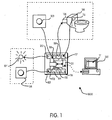
- the distress signaling system 1000 is shown according to a preferred and non-limiting embodiment of the present invention.
- the distress signaling system 1000 is configured for communicating distress signals through an electronic plumbing control system.
- the system 1000 includes an electronic plumbing controller 101, a distress signaling device 103, and a distress indicator 111.
- the electronic plumbing controller 101 may include one or more circuits and/or computing devices, including but not limited to one or more microprocessors 109 and input/output ports 113-120. It will be appreciated that the electronic plumbing controller 101 may also include any number of controllers, processors, computers, and/or the like, and that input to and output from the plumbing controller 101 may occur in any number of ways.
- a port may allow input and output, just input, or just output.
- input/output ports may also include one or more wired or wireless interfaces that allow for data to be inputted to and outputted by the controller 101. Other arrangements are possible.
- the electronic plumbing controller 101 may be used to operate and control one or more plumbing fixtures 106, such as an electronic plumbing fixture 106 associated with a plumbing appliance 105.
- a plumbing appliance 105 may include, for example, a toilet, shower, faucet, and/or the like, and a plumbing fixture 106 may include an electronic valve, regulator, and/or the like. It will be appreciated that any number of plumbing appliances 105 and fixtures 106 may be used with the system 1000.
- the electronic plumbing controller 101 may cause a toilet to be flushed, cause a shower or faucet to turn on, regulate the use of an appliance, restrict the use of an appliance to certain time periods or frequencies, and/or the like.
- the electronic plumbing controller 101 may flush a toilet in response to a signal from a trigger device on the toilet, or in response to a signal from a remote computer or controller. It will be appreciated by those skilled in the art that the electronic plumbing controller 101 may control various plumbing fixtures in various ways.
- a fixture 106 may include, for example, a solenoid-driven flush valve for flushing a toilet or a regulator valve for a shower or faucet.
- a fixture may also include any other device or system that regulates, controls, operates, and/or provides fluids to or from a plumbing appliance.
- a trigger device 112 is in communication with the plumbing controller 101 and is programmed, configured, and/or adapted to operate the plumbing fixture 106 (e.g., cause the fixture to flush, start, stop, and/or the like). In some non-limiting embodiments, multiple trigger devices 112 may provide various functions for plumbing fixtures 106.
- a trigger device may include, for example, a button, switch, lever, sensor, and/or the like, that can be activated based on physical actuation, touch, motion, proximity, and/or the like.
- a distress indicator 104 may include, but is not limited to, one or more light-emitting diodes (LED), light bulbs, audible alarms, alerts on a graphical user interface, and/or the like. Further, in non-limiting embodiments, the LEDs or bulbs may be any number of colors, and may be configured to flash when activated. In some examples, lights of different colors may be provided for different indications.
- the distress indicator 104 may also be a combination of visual and audible alarms. In some non-limiting embodiments, the distress indicator 104 may be in multiple forms. For example, the distress indicator 104 may be an LED mounted on a wall or control panel, and may also be a visual or audible alert displayed or emitted from a management computer. It will be appreciated that various other arrangements are possible.
- the I/O ports 113-120 on the plumbing controller 101 may be in electrical communication with a microprocessor 109 or other like control device.
- the plumbing controller 101 may also include a communication device for interfacing the I/O ports 113-120 with the trigger device 112, distress signaling device 103, distress indicator 104, fixture 106, appliance 105, and/or other systems and devices.
- separate electronic plumbing controllers 101 in communication with a common plumbing network, may be used to respectively operate the fixture 106 and the distress indicator 104.
- a single electronic plumbing controller 101 may be used to operate the fixture 106 and the distress indicator 104. It will be appreciated that various other arrangements are possible.
- the distress signaling device 103 and/or trigger device 112 may include a button or other like switching or sensing arrangement that activates or produces a signal based on actuation, touch, proximity, and/or the like. It will be appreciated that the distress signaling device 103 and/or trigger device 112 may be any type of input device or sensor such as, but not limited to, one or more accelerometers, capacitive touch sensors, pressure transducers, switches, buttons, infrared sensors, proximity sensors, and/or the like.
- the distress signaling device 103 may be located on a wall of a cell or unit, for example, or may be affixed to a floor, a piece of furniture, an appliance 105, a cell door, or the like.
- the trigger device 112 may be located adjacent to or on an associated appliance 105 or fixture 106, or may alternatively be located anywhere else that is accessible by a user of the appliance 105.
- a reset device 108 may be in communication with the electronic plumbing controller 101.
- the reset device 108 may be located adjacent the distress indicator 104, in a central control room, in a hallway, in a chase area, and/or the like.
- the reset device 108 is programmed and/or configured to, upon activation, cause the distress indicator 104 to turn off or deactivate once it has already been activated and is in an activated state.
- the reset device 108 may be a two-position key switch that requires a key to activate. Using a two-position key switch, a momentary position (e.g., turned to the right or left) may deactivate the distress indicator 104.
- the reset device 108 may be configured to allow verification and/or authentication to be provided with keypads, wireless signals (e.g., radio frequencies), biometrics, and/or the like. Further, the reset device 108 may include any type of input device or sensor such as, but not limited to, switches, buttons, accelerometers, capacitive touch sensors, pressure transducers, and/or the like. In non-limiting embodiments, the reset device 108 may be a computer, such as a workstation or mobile device, and a graphical user interface may present options that allow an operator to deactivate the distress indicator 104.
- the electronic plumbing controller 101 includes a communications port 131 that is configured to communicate with a management computer 135.
- the communications port 131 may communicate with the management computer 135 over a wired connection, local area network, wide area network, and/or other like communications network.
- a server may facilitate communication between the communications port 131 and the management computer 135, and in non-limiting embodiments the communication may occur directly without the use of a server.
- the management computer 135 may be any computing device such as, for example, a desktop or laptop computer, a mobile device, and/or the like.
- the management computer 135 includes software that is programmed and/or configured to communicate with the electronic plumbing controller 101.
- the software may be specially purposed for communication with the electronic plumbing controller 101, or a web browser that communicates with the electronic plumbing controller 101 through a web server.
- Various other implementations are possible.
- the management computer 135 may include a processor and a display device and be programmed, configured, and/or adapted to generate one or more graphical user interfaces 111 that display menu screens, facility or building maps, and various selectable options on the display device.
- the graphical user interface 111 may display a view of rooms and/or units in a building or facility, indicating the locations of distress signaling devices 103, appliances 105, and/or fixtures 106.
- the selectable options may allow users of the management computer 135 to operate and monitor the fixtures 106 associated with plumbing appliances 105, and may also allow users to view the rooms and/or units that have activated a distress signaling device 103.
- Selectable options may also be provided to reset (i.e., deactivate or turn off) distress indicators 104, set lockout times for the fixtures 106, and manage other aspects of the plumbing and distress systems.
- the selectable options on the user interface 111 may include, but are not limited to, drop-down boxes, radio buttons, check boxes, buttons, icons, input fields, and/or the like.
- the distress signaling system 1000 is adapted to be installed in an institutional environment, such as a correctional facility.
- the system 1000 allows for detainees to signal that they are distressed and in need of help from correctional staff.
- the distress signaling system 1000 may be used in any environment or facility in which a distress signal is desired.
- the system 1000 may be implemented in a medical facility where patients using a restroom may be at risk of slipping or otherwise injuring themselves.
- Various other arrangements and uses are possible.
- the plumbing controller 101 may be located in a chase area 120 outside of a unit or cell and is in communication with the trigger device 112, distress signaling device 103, and plumbing appliance 105 through wires, cables, wireless devices, and/or the like.
- the trigger device 112, plumbing appliance 105, and distress signaling device 103 may be arranged anywhere in the unit or cell. In the example shown in FIG. 2 , two cells share a common chase area 120 and a common controller 101.
- the distress indicator 104 may be located outside of the chase 120 and the cells, at a distance from or adjacent to each cell. Moreover, distress indicators 104 and a reset device 108 are positioned in an area accessible and visible to correctional staff.
- the electronic plumbing controller 101 includes a number of I/O ports that are used to control plumbing appliances (not shown) and distress indicators (not shown). In the example shown, the left-most ports are used for output, and the right-most ports are used for input. For example, one or more distress signaling devices (not shown) and trigger devices (not shown) may interface with the input ports of the controller 101, and one or more distress indicators (not shown) and plumbing fixtures (not shown) may interface with the output ports of the controller 101.
- the controller 101 depicted in FIG. 3 includes eight (8) input ports and eight (8) output ports, although it will be appreciated that several different types of controllers 101, with various types and numbers of ports, may be used.
- communication ports 131, 133 are used to network multiple plumbing controllers 101 together and to communicate with one or more management computers 135, 137.
- communications port 131 may interface with a first management computer 135 or a network in communication with the first management computer 135.
- Another communications port 133 may communicate with other plumbing controllers, allowing multiple controllers to be linked or chained together.
- a USB network interface 132 is used to interface between the communications port 131 of the controller 101 and the first management computer 135. It will be appreciated that various interfacing and communications arrangements may be used to effectuate communication between components of the system 1000.
- the first (e.g., local) management computer 135 may be used to manage a first group of controllers 101 that are situated in a particular region or area of a building.
- the local management computer 135 may include a display device 136 and an input device, as examples.
- Converters 139 e.g., fiber/Ethernet converters
- the management computers 135, 137 may be any computer, remote or local to the facility or building, programmed, configured, and/or adapted to communicate with the system 1000.
- a user's computer or device may become a central management computer 137 by logging into a network and receiving data configured to generate a user interface through, for example, a web browser or other software application.
- the central management computer 137 communicates with an existing fiber network via a converter 139.
- various arrangements may be used to communicate between the controller 101 and the management computers 135, 137 including, but not limited to, wireless communication over a network, direct controller-to-computer wireless communication, secure web-based communication, hardwired network connections, and/or the like.
- the central management computer 137 may be programmed and/or configured to communicate with all of the controllers 101 in a building or facility, or multiple facilities.
- the central management computer 137 may therefore be used to centrally and/or remotely control and manage plumbing fixtures and distress indicators.
- the central management computer 137 may have administrative rights over the other management computers 135 for a region or area, and may be configured to override and/or monitor the other management computers 135.
- the management computers 135, 137 may be configured, programmed, and/or adapted to display one or more graphical user interfaces on the displays 136, 138 that provide visual representations and various selectable options, as already described.
- the management computers 135, 137 may include display devices 136, 138 that are touch-sensitive and also serve as an input device.
- the user of the management computers 135, 137, through the user interfaces, may be able to view any rooms, units, or cells that have activated a distress signaling device.
- the user interfaces may also be configured to serve as a reset device, providing selectable options to disable or deactivate a distress indicator.
- the software executed by the management computers 135, 137 translates these commands into signals that are communicated to the electronic plumbing controller 101.
- Various other selectable options may, for example, enable or disable portions of the distress signaling system, enable or disable distress signaling devices in a particular room, unit, or cell, display statistics regarding the usage of the distress signaling devices and indicators, set lock-out times for all or some of the distress signaling devices, and/or the like.
- the management computer 135 may be limited to only reset or deactivate (e.g., turn off, silence, etc.) the distress indicators or alarm in certain conditions or situations.
- the management computer 135 may allow a user, through the user interface, to reset or deactivate the distress indicators or alarm only for a predetermined period of time (e.g., 90 seconds) after being activated. After this time, the distress indicator or alarm would have to be reset or deactivated at a physical reset device located near the distress indictor or elsewhere ( e.g ., in a chase area, hallway, room, etc.). It will be appreciated that various different periods of time may be used. Further, in other non-limiting embodiments, the management computer 135 may be able to always reset or deactivate the distress indicators, regardless of the time that has passed since being activated.
- the distress signaling device 103 may serve as a trigger device 112 for a fixture 106 associated with an appliance 105.
- the at least one distress signaling device 103 may be a trigger device 112 for a fixture 106, and may be programmed, configured, and/or adapted to activate the fixture 106 based on a first input, and to activate the distress indicator based on a second input that is different from the first input.
- a trigger device 112 for a plumbing fixture 106 may activate the fixture 106 if it is actuated once, and may activate the distress indicator 104 if repeatedly actuated, actuated for a predetermined time period, actuated with a predetermined force, and/or actuated a predetermined number of times during a predetermined time period, as examples. It will be appreciated that numerous other arrangements are possible in which a single trigger device 112 serves to operate or activate both a plumbing fixture 106 and a distress indicator 104 in response to different inputs.
Landscapes
- Physics & Mathematics (AREA)
- General Physics & Mathematics (AREA)
- Business, Economics & Management (AREA)
- Emergency Management (AREA)
- Engineering & Computer Science (AREA)
- Computer Security & Cryptography (AREA)
- Computer Networks & Wireless Communication (AREA)
- Health & Medical Sciences (AREA)
- Electromagnetism (AREA)
- Life Sciences & Earth Sciences (AREA)
- Public Health (AREA)
- Water Supply & Treatment (AREA)
- Hydrology & Water Resources (AREA)
- Human Computer Interaction (AREA)
- Gerontology & Geriatric Medicine (AREA)
- General Health & Medical Sciences (AREA)
- Automation & Control Theory (AREA)
- Alarm Systems (AREA)
- Selective Calling Equipment (AREA)
- Emergency Alarm Devices (AREA)
- Transmitters (AREA)
- Audible And Visible Signals (AREA)
Claims (8)
- Notfallsignalisierungssystem zur Kommunikation von Notsignalen durch ein elektronisches Sanitärsteuerungssystem, das aufweist:eine Sanitärsteuerungseinrichtung (101), die zum Betätigen mindestens einer Sanitäranwendung (105) ausgebildet ist;mindestens einen Notfallindikator (104) in Kommunikation mit der Sanitärsteuerungseinrichtung (101); undmindestens eine Notfallsignalisierungsvorrichtung (103) in Kommunikation mit der Sanitärsteuerungseinrichtung (101), wobei eine Aktivierung der mindestens einen Notfallsignalisierungsvorrichtung (103) eine Aktivierung des mindestens einen Notfallindikators (104) bewirkt,wobeisich die mindestens eine Notfallsignalisierungsvorrichtung (103) innerhalb mindestens einer Einheit oder Zelle befindet und für einen Häftling in der Einheit oder Zelle sichtbar ist, wobei sich der mindestens eine Notfallindikator (104) außerdem der mindestens einen Einheit oder Zelle befindet und für Justizvollzugspersonal zugänglich und sichtbar ist, wobei die mindestens eine Notfallsignalisierungsvorrichtung (103) mindestens eine Auslösevorrichtung (112) für die mindestens eine Sanitäranwendung (105) aufweist, wobei die mindestens eine Auslösevorrichtung (112) ausgebildet ist zum Aktivieren der mindestens einen Sanitäranwendung (105) basierend auf einer ersten Eingabe, die eine erste Betätigungsart der mindestens einen Auslösevorrichtung (112) umfasst, und zum Aktivieren des mindestens einen Notfallindikators (104) basierend auf einer zweite Eingabe, die eine zweite Betätigungsart der mindestens einen Auslösevorrichtung (112) umfasst, und wobei sich die erste Betätigungsart der mindestens einen Auslösevorrichtung (112) von der zweiten Betätigungsart der mindestens einen Auslösevorrichtung (112) unterscheidet.
- Notfallsignalisierungssystem nach Anspruch 1, ferner mit einer Rückstellvorrichtung in Kommunikation mit der Sanitärsteuerungseinrichtung (101), wobei die Rückstellvorrichtung zum Deaktivieren des mindestens einen Notfallindikators (104) ausgebildet ist.
- Notfallsignalisierungssystem nach Anspruch 2, wobei die Rückstellvorrichtung zum Deaktivieren des mindestens einen Notfallindikators (104) ausgebildet ist als Reaktion auf einen in die Rückstellvorrichtung eingesetzten und gedrehten physikalischen Schlüssel.
- Notfallsignalisierungssystem nach Anspruch 1, ferner mit mindestens einem Verwaltungscomputer, der zum Anzeigen mindestens einer graphischen Benutzeroberfläche ausgebildet ist, wobei der mindestens eine Notfallindikator (104) eine Warnung umfasst, die auf der mindestens einen graphischen Benutzeroberfläche angezeigt wird.
- Notfallsignalisierungssystem nach Anspruch 4, wobei der mindestens eine Verwaltungscomputerferner zum Deaktivieren des mindestens einen Notfallindikators (104) ausgebildet ist, vorzugsweise lediglich während eines vorbestimmten Zeitraums.
- Notfallsignalisierungssystem nach Anspruch 1, wobei der mindestens eine Notfallindikators (104) mindestens eine Lichtabgabevorrichtung aufweist.
- Verfahren zur Signalisierung eines Notfalls mit einer Sanitärsteuerungseinrichtung (101) in einer Vollzugsanstalt, mit folgenden Schritten:Bereitstellen, in der Vollzugsanstalt, eines Sanitärsteuerungssystems, das zum Betätigen mindestens einer Einrichtung (106) ausgebildet ist;Empfangen, mittels des Sanitärsteuerungssystems, einer Eingabe von mindestens einer Notfallsignalisierungsvorrichtung (103) in mindestens einer Einheit der Justizvollzugsanstalt und für einen Häftling in der mindestens einen Einheit oder Zelle sichtbar; undAktivieren, mit dem Sanitärsteuerungssystems, mindestens eines Notfallindikators (104) als Reaktion auf die Eingabe, wobei sich der mindestens eine Notfallindikator (104) außerhalb der mindestens einen Einheit oder Zelle befindet und für Justizvollzugspersonal zugänglich und sichtbar ist,wobei die mindestens eine Notfallsignalisierungsvorrichtung (103) mindestens eine Auslösevorrichtung (112) aufweist, die zum Betätigen der mindestens einen Einrichtung (106) ausgebildet ist, wobei das Verfahren ferner das Bestimmen umfasst, mit mindestens einem zumindest teilweise auf der Eingabe basierendem Prozessor, ob die mindestens eine Einrichtung (106) betätigt werden soll oder ob der mindestens eine Notfallindikator (104) aktiviert werden soll, undwobei die mindestens eine Einrichtung (106) betätigt wird, wenn die mindestens eine Auslösevorrichtung (112) einmal aktiviert wird, und wobei der mindestens eine Notfallindikator (104) als Reaktion auf die Eingabe aktiviert wird, wenn die mindestens eine Auslösevorrichtung (112) auf mindestens eine der folgenden Arten betätigt wird: wiederholt betätigt, für einen vorbestimmten Zeitraum betätigt, für eine vorbestimmte Anzahl von Fällen während eines bestimmten Zeitraums betätigt oder jegliche Kombinationen daraus.
- Verfahren nach Anspruch 7, ferner umfassend:Empfangen, mittels des Sanitärsteuerungssystems, einer Eingabe von der mindestens einen Rückstellvorrichtung; undDeaktivieren des mindestens einen Notfallindikators (104) als Reaktion auf die Eingabe von der mindestens einen Rückstellvorrichtung.
Priority Applications (2)
| Application Number | Priority Date | Filing Date | Title |
|---|---|---|---|
| HRP20201362TT HRP20201362T1 (hr) | 2013-12-18 | 2014-12-18 | Vodovodni sustav upravljanja sa signalom opasnosti |
| EP20175371.2A EP3731200B1 (de) | 2013-12-18 | 2014-12-18 | Rohrleitungssteuerungssystem mit notsignal |
Applications Claiming Priority (3)
| Application Number | Priority Date | Filing Date | Title |
|---|---|---|---|
| US201361917550P | 2013-12-18 | 2013-12-18 | |
| US14/573,608 US9728073B2 (en) | 2013-12-18 | 2014-12-17 | Plumbing control system with distress signal |
| PCT/US2014/071126 WO2015095505A1 (en) | 2013-12-18 | 2014-12-18 | Plumbing control system with distress signal |
Related Child Applications (2)
| Application Number | Title | Priority Date | Filing Date |
|---|---|---|---|
| EP20175371.2A Division EP3731200B1 (de) | 2013-12-18 | 2014-12-18 | Rohrleitungssteuerungssystem mit notsignal |
| EP20175371.2A Division-Into EP3731200B1 (de) | 2013-12-18 | 2014-12-18 | Rohrleitungssteuerungssystem mit notsignal |
Publications (3)
| Publication Number | Publication Date |
|---|---|
| EP3084739A1 EP3084739A1 (de) | 2016-10-26 |
| EP3084739A4 EP3084739A4 (de) | 2017-09-27 |
| EP3084739B1 true EP3084739B1 (de) | 2020-07-22 |
Family
ID=53403687
Family Applications (2)
| Application Number | Title | Priority Date | Filing Date |
|---|---|---|---|
| EP20175371.2A Active EP3731200B1 (de) | 2013-12-18 | 2014-12-18 | Rohrleitungssteuerungssystem mit notsignal |
| EP14872315.8A Active EP3084739B1 (de) | 2013-12-18 | 2014-12-18 | Rohrleitungssteuerungssystem mit notsignal |
Family Applications Before (1)
| Application Number | Title | Priority Date | Filing Date |
|---|---|---|---|
| EP20175371.2A Active EP3731200B1 (de) | 2013-12-18 | 2014-12-18 | Rohrleitungssteuerungssystem mit notsignal |
Country Status (7)
| Country | Link |
|---|---|
| US (2) | US9728073B2 (de) |
| EP (2) | EP3731200B1 (de) |
| CA (1) | CA2934329C (de) |
| ES (2) | ES3064189T3 (de) |
| HR (1) | HRP20201362T1 (de) |
| MX (2) | MX381282B (de) |
| WO (1) | WO2015095505A1 (de) |
Families Citing this family (8)
| Publication number | Priority date | Publication date | Assignee | Title |
|---|---|---|---|---|
| US20080201158A1 (en) | 2007-02-15 | 2008-08-21 | Johnson Mark D | System and method for visitation management in a controlled-access environment |
| US10572961B2 (en) | 2016-03-15 | 2020-02-25 | Global Tel*Link Corporation | Detection and prevention of inmate to inmate message relay |
| US9609121B1 (en) | 2016-04-07 | 2017-03-28 | Global Tel*Link Corporation | System and method for third party monitoring of voice and video calls |
| US9963863B2 (en) * | 2016-09-08 | 2018-05-08 | Sdb Ip Holdings, Llc | Plumbing control system, method, and apparatus and preventing repeated use of an appliance with feedback |
| US10187288B2 (en) * | 2017-03-09 | 2019-01-22 | Caterpillar Inc. | Communicating data link information using a light source |
| US10027797B1 (en) * | 2017-05-10 | 2018-07-17 | Global Tel*Link Corporation | Alarm control for inmate call monitoring |
| US10225396B2 (en) | 2017-05-18 | 2019-03-05 | Global Tel*Link Corporation | Third party monitoring of a activity within a monitoring platform |
| US10860786B2 (en) | 2017-06-01 | 2020-12-08 | Global Tel*Link Corporation | System and method for analyzing and investigating communication data from a controlled environment |
Family Cites Families (21)
| Publication number | Priority date | Publication date | Assignee | Title |
|---|---|---|---|---|
| US3803579A (en) * | 1972-12-29 | 1974-04-09 | M Compton | Automatic alarm system for bathroom |
| US6018827A (en) | 1989-07-20 | 2000-02-01 | Sloan Valve Company | Push button assembly for control of plumbing fixtures in prisons and the like |
| US5307524A (en) * | 1992-03-25 | 1994-05-03 | Veal Bennie N | Automatic toilet seat device |
| FI109843B (fi) * | 1998-04-09 | 2002-10-15 | Ist Oy | Ihmisen fysiologisilla signaaleilla ohjautuva kiinteistöautomaation ohjausjärjestelmä |
| US6453687B2 (en) * | 2000-01-07 | 2002-09-24 | Robertshaw Controls Company | Refrigeration monitor unit |
| US6769443B2 (en) | 2002-04-29 | 2004-08-03 | I-Con Systems, Inc. | Plumbing control system with signal recognition |
| WO2006042053A2 (en) * | 2004-10-07 | 2006-04-20 | Richard Quintana | Intelligent flow control unit and water management system |
| US8590067B2 (en) * | 2005-02-03 | 2013-11-26 | Danco, Inc. | Control of toilet bowl fill flow |
| US7304569B2 (en) | 2005-08-03 | 2007-12-04 | Sloan Valve Company | Networking of discrete plumbing devices |
| US7969318B2 (en) | 2007-06-15 | 2011-06-28 | Matt White | Flow detector with alarm features |
| KR20120081154A (ko) * | 2009-09-16 | 2012-07-18 | 라르스 포스베르그 | 사람들로 하여금 손을 씻도록 동기 부여 및/또는 유발하는 시스템 및 방법 |
| US8561626B2 (en) | 2010-04-20 | 2013-10-22 | Masco Corporation Of Indiana | Capacitive sensing system and method for operating a faucet |
| GB201100738D0 (en) * | 2011-01-17 | 2011-03-02 | Wallgate Ltd | Control apparatus |
| US9041534B2 (en) * | 2011-01-26 | 2015-05-26 | En-Gauge, Inc. | Fluid container resource management |
| US20130069675A1 (en) * | 2011-03-25 | 2013-03-21 | Dorlen Products, Inc. | Conductive fluid leak detector |
| US9371639B1 (en) * | 2011-07-02 | 2016-06-21 | Danco, Inc. | Toilet flush valve with bowl overflow prevention |
| GB2499837B (en) * | 2012-03-01 | 2018-02-21 | Phoenix Product Development Ltd | Toilet Systems |
| US9123230B2 (en) * | 2012-05-21 | 2015-09-01 | Frank T. Rogers | Sewer backup alarm |
| US10760255B2 (en) * | 2013-07-15 | 2020-09-01 | As America, Inc. | Self cleaning toilet assembly and system |
| US9127445B2 (en) * | 2013-11-19 | 2015-09-08 | Tristram C. Dunn | Sewer alarm apparatus with probe extending through a monitored pipe |
| CN105608838B (zh) * | 2016-03-04 | 2018-11-09 | 京东方科技集团股份有限公司 | 一种监护系统及方法 |
-
2014
- 2014-12-17 US US14/573,608 patent/US9728073B2/en active Active
- 2014-12-18 ES ES20175371T patent/ES3064189T3/es active Active
- 2014-12-18 ES ES14872315T patent/ES2820748T3/es active Active
- 2014-12-18 WO PCT/US2014/071126 patent/WO2015095505A1/en not_active Ceased
- 2014-12-18 EP EP20175371.2A patent/EP3731200B1/de active Active
- 2014-12-18 EP EP14872315.8A patent/EP3084739B1/de active Active
- 2014-12-18 MX MX2018015166A patent/MX381282B/es unknown
- 2014-12-18 CA CA2934329A patent/CA2934329C/en active Active
- 2014-12-18 HR HRP20201362TT patent/HRP20201362T1/hr unknown
- 2014-12-18 MX MX2016007886A patent/MX361492B/es active IP Right Grant
-
2017
- 2017-06-30 US US15/639,057 patent/US10186141B2/en active Active
Non-Patent Citations (1)
| Title |
|---|
| None * |
Also Published As
| Publication number | Publication date |
|---|---|
| ES3064189T3 (en) | 2026-04-23 |
| MX2016007886A (es) | 2016-09-13 |
| US20150206417A1 (en) | 2015-07-23 |
| ES2820748T3 (es) | 2021-04-22 |
| EP3731200A1 (de) | 2020-10-28 |
| MX361492B (es) | 2018-12-07 |
| US9728073B2 (en) | 2017-08-08 |
| US20170301219A1 (en) | 2017-10-19 |
| US10186141B2 (en) | 2019-01-22 |
| MX381282B (es) | 2025-03-12 |
| EP3731200B1 (de) | 2026-02-11 |
| CA2934329A1 (en) | 2015-06-25 |
| EP3084739A4 (de) | 2017-09-27 |
| EP3084739A1 (de) | 2016-10-26 |
| WO2015095505A1 (en) | 2015-06-25 |
| CA2934329C (en) | 2020-11-17 |
| HRP20201362T1 (hr) | 2020-11-27 |
Similar Documents
| Publication | Publication Date | Title |
|---|---|---|
| US10186141B2 (en) | Plumbing control system with distress signal | |
| EP3494262B1 (de) | Rohrleitungssteuerungssystem, -verfahren und -vorrichtung zur verhinderung einer wiederholten verwendung eines geräts mit rückmeldung | |
| US11847905B2 (en) | Cloud-connected occupancy lights and status indication | |
| US11016639B2 (en) | Multiple outlet shower control | |
| US20160376773A1 (en) | Method for Automatic Water Leak Detection and Mitigation of Residential and Commercial Water Supply Systems | |
| US20130002440A1 (en) | Illuminated fire extinguisher cabinet | |
| US12006731B2 (en) | Touchless, pushbutton exit devices, systems and methods thereof | |
| KR101871063B1 (ko) | 모듈러 주택의 내부관리 스마트 시스템 | |
| WO2010111981A3 (en) | Modular control and indicating panel, its use and a method of controlling building alarm systems | |
| CN103365219B (zh) | 用于监视和控制过程控制系统的目标操作设备的系统和方法 | |
| ES2826564T3 (es) | Control para iluminación de edificios y otras instalaciones técnicas domésticas | |
| EP2575114A2 (de) | Alarmsteuerung | |
| TWI578851B (zh) | 照明設備控制系統及方法 | |
| KR20160033323A (ko) | 화장실 안내 및 관리 장치 | |
| EP3047825A1 (de) | Direktionale Führungsvorrichtung | |
| WO2025046211A1 (en) | Elevator safety systems | |
| JP2015095013A (ja) | 防災監視制御盤 | |
| US20160311651A1 (en) | Passenger conveyor system monitoring device and method for installing the same | |
| KR20160066882A (ko) | 문열림 알림장치 |
Legal Events
| Date | Code | Title | Description |
|---|---|---|---|
| PUAI | Public reference made under article 153(3) epc to a published international application that has entered the european phase |
Free format text: ORIGINAL CODE: 0009012 |
|
| 17P | Request for examination filed |
Effective date: 20160713 |
|
| AK | Designated contracting states |
Kind code of ref document: A1 Designated state(s): AL AT BE BG CH CY CZ DE DK EE ES FI FR GB GR HR HU IE IS IT LI LT LU LV MC MK MT NL NO PL PT RO RS SE SI SK SM TR |
|
| AX | Request for extension of the european patent |
Extension state: BA ME |
|
| DAX | Request for extension of the european patent (deleted) | ||
| A4 | Supplementary search report drawn up and despatched |
Effective date: 20170828 |
|
| RIC1 | Information provided on ipc code assigned before grant |
Ipc: G08B 21/00 20060101AFI20170822BHEP Ipc: G05D 7/06 20060101ALI20170822BHEP |
|
| STAA | Information on the status of an ep patent application or granted ep patent |
Free format text: STATUS: EXAMINATION IS IN PROGRESS |
|
| 17Q | First examination report despatched |
Effective date: 20190214 |
|
| GRAP | Despatch of communication of intention to grant a patent |
Free format text: ORIGINAL CODE: EPIDOSNIGR1 |
|
| STAA | Information on the status of an ep patent application or granted ep patent |
Free format text: STATUS: GRANT OF PATENT IS INTENDED |
|
| INTG | Intention to grant announced |
Effective date: 20200221 |
|
| RIN1 | Information on inventor provided before grant (corrected) |
Inventor name: BUSH, SHAWN, D. Inventor name: ELLIOTT, DONALD, RAY |
|
| GRAS | Grant fee paid |
Free format text: ORIGINAL CODE: EPIDOSNIGR3 |
|
| GRAA | (expected) grant |
Free format text: ORIGINAL CODE: 0009210 |
|
| STAA | Information on the status of an ep patent application or granted ep patent |
Free format text: STATUS: THE PATENT HAS BEEN GRANTED |
|
| AK | Designated contracting states |
Kind code of ref document: B1 Designated state(s): AL AT BE BG CH CY CZ DE DK EE ES FI FR GB GR HR HU IE IS IT LI LT LU LV MC MK MT NL NO PL PT RO RS SE SI SK SM TR |
|
| REG | Reference to a national code |
Ref country code: GB Ref legal event code: FG4D |
|
| REG | Reference to a national code |
Ref country code: CH Ref legal event code: EP |
|
| REG | Reference to a national code |
Ref country code: DE Ref legal event code: R096 Ref document number: 602014068140 Country of ref document: DE |
|
| REG | Reference to a national code |
Ref country code: AT Ref legal event code: REF Ref document number: 1294145 Country of ref document: AT Kind code of ref document: T Effective date: 20200815 |
|
| REG | Reference to a national code |
Ref country code: IE Ref legal event code: FG4D |
|
| REG | Reference to a national code |
Ref country code: HR Ref legal event code: TUEP Ref document number: P20201362T Country of ref document: HR |
|
| REG | Reference to a national code |
Ref country code: HR Ref legal event code: T1PR Ref document number: P20201362 Country of ref document: HR |
|
| REG | Reference to a national code |
Ref country code: LT Ref legal event code: MG4D |
|
| REG | Reference to a national code |
Ref country code: HR Ref legal event code: ODRP Ref document number: P20201362 Country of ref document: HR Payment date: 20201210 Year of fee payment: 7 |
|
| REG | Reference to a national code |
Ref country code: AT Ref legal event code: MK05 Ref document number: 1294145 Country of ref document: AT Kind code of ref document: T Effective date: 20200722 |
|
| PG25 | Lapsed in a contracting state [announced via postgrant information from national office to epo] |
Ref country code: FI Free format text: LAPSE BECAUSE OF FAILURE TO SUBMIT A TRANSLATION OF THE DESCRIPTION OR TO PAY THE FEE WITHIN THE PRESCRIBED TIME-LIMIT Effective date: 20200722 Ref country code: NO Free format text: LAPSE BECAUSE OF FAILURE TO SUBMIT A TRANSLATION OF THE DESCRIPTION OR TO PAY THE FEE WITHIN THE PRESCRIBED TIME-LIMIT Effective date: 20201022 Ref country code: LT Free format text: LAPSE BECAUSE OF FAILURE TO SUBMIT A TRANSLATION OF THE DESCRIPTION OR TO PAY THE FEE WITHIN THE PRESCRIBED TIME-LIMIT Effective date: 20200722 Ref country code: GR Free format text: LAPSE BECAUSE OF FAILURE TO SUBMIT A TRANSLATION OF THE DESCRIPTION OR TO PAY THE FEE WITHIN THE PRESCRIBED TIME-LIMIT Effective date: 20201023 Ref country code: PT Free format text: LAPSE BECAUSE OF FAILURE TO SUBMIT A TRANSLATION OF THE DESCRIPTION OR TO PAY THE FEE WITHIN THE PRESCRIBED TIME-LIMIT Effective date: 20201123 Ref country code: BG Free format text: LAPSE BECAUSE OF FAILURE TO SUBMIT A TRANSLATION OF THE DESCRIPTION OR TO PAY THE FEE WITHIN THE PRESCRIBED TIME-LIMIT Effective date: 20201022 Ref country code: SE Free format text: LAPSE BECAUSE OF FAILURE TO SUBMIT A TRANSLATION OF THE DESCRIPTION OR TO PAY THE FEE WITHIN THE PRESCRIBED TIME-LIMIT Effective date: 20200722 Ref country code: AT Free format text: LAPSE BECAUSE OF FAILURE TO SUBMIT A TRANSLATION OF THE DESCRIPTION OR TO PAY THE FEE WITHIN THE PRESCRIBED TIME-LIMIT Effective date: 20200722 |
|
| PG25 | Lapsed in a contracting state [announced via postgrant information from national office to epo] |
Ref country code: IS Free format text: LAPSE BECAUSE OF FAILURE TO SUBMIT A TRANSLATION OF THE DESCRIPTION OR TO PAY THE FEE WITHIN THE PRESCRIBED TIME-LIMIT Effective date: 20201122 Ref country code: PL Free format text: LAPSE BECAUSE OF FAILURE TO SUBMIT A TRANSLATION OF THE DESCRIPTION OR TO PAY THE FEE WITHIN THE PRESCRIBED TIME-LIMIT Effective date: 20200722 Ref country code: RS Free format text: LAPSE BECAUSE OF FAILURE TO SUBMIT A TRANSLATION OF THE DESCRIPTION OR TO PAY THE FEE WITHIN THE PRESCRIBED TIME-LIMIT Effective date: 20200722 Ref country code: LV Free format text: LAPSE BECAUSE OF FAILURE TO SUBMIT A TRANSLATION OF THE DESCRIPTION OR TO PAY THE FEE WITHIN THE PRESCRIBED TIME-LIMIT Effective date: 20200722 |
|
| PG25 | Lapsed in a contracting state [announced via postgrant information from national office to epo] |
Ref country code: NL Free format text: LAPSE BECAUSE OF FAILURE TO SUBMIT A TRANSLATION OF THE DESCRIPTION OR TO PAY THE FEE WITHIN THE PRESCRIBED TIME-LIMIT Effective date: 20200722 |
|
| REG | Reference to a national code |
Ref country code: ES Ref legal event code: FG2A Ref document number: 2820748 Country of ref document: ES Kind code of ref document: T3 Effective date: 20210422 |
|
| REG | Reference to a national code |
Ref country code: DE Ref legal event code: R097 Ref document number: 602014068140 Country of ref document: DE |
|
| PG25 | Lapsed in a contracting state [announced via postgrant information from national office to epo] |
Ref country code: CZ Free format text: LAPSE BECAUSE OF FAILURE TO SUBMIT A TRANSLATION OF THE DESCRIPTION OR TO PAY THE FEE WITHIN THE PRESCRIBED TIME-LIMIT Effective date: 20200722 Ref country code: DK Free format text: LAPSE BECAUSE OF FAILURE TO SUBMIT A TRANSLATION OF THE DESCRIPTION OR TO PAY THE FEE WITHIN THE PRESCRIBED TIME-LIMIT Effective date: 20200722 Ref country code: RO Free format text: LAPSE BECAUSE OF FAILURE TO SUBMIT A TRANSLATION OF THE DESCRIPTION OR TO PAY THE FEE WITHIN THE PRESCRIBED TIME-LIMIT Effective date: 20200722 Ref country code: SM Free format text: LAPSE BECAUSE OF FAILURE TO SUBMIT A TRANSLATION OF THE DESCRIPTION OR TO PAY THE FEE WITHIN THE PRESCRIBED TIME-LIMIT Effective date: 20200722 Ref country code: EE Free format text: LAPSE BECAUSE OF FAILURE TO SUBMIT A TRANSLATION OF THE DESCRIPTION OR TO PAY THE FEE WITHIN THE PRESCRIBED TIME-LIMIT Effective date: 20200722 |
|
| PLBE | No opposition filed within time limit |
Free format text: ORIGINAL CODE: 0009261 |
|
| STAA | Information on the status of an ep patent application or granted ep patent |
Free format text: STATUS: NO OPPOSITION FILED WITHIN TIME LIMIT |
|
| PG25 | Lapsed in a contracting state [announced via postgrant information from national office to epo] |
Ref country code: AL Free format text: LAPSE BECAUSE OF FAILURE TO SUBMIT A TRANSLATION OF THE DESCRIPTION OR TO PAY THE FEE WITHIN THE PRESCRIBED TIME-LIMIT Effective date: 20200722 |
|
| 26N | No opposition filed |
Effective date: 20210423 |
|
| PG25 | Lapsed in a contracting state [announced via postgrant information from national office to epo] |
Ref country code: SK Free format text: LAPSE BECAUSE OF FAILURE TO SUBMIT A TRANSLATION OF THE DESCRIPTION OR TO PAY THE FEE WITHIN THE PRESCRIBED TIME-LIMIT Effective date: 20200722 |
|
| REG | Reference to a national code |
Ref country code: CH Ref legal event code: PL |
|
| PG25 | Lapsed in a contracting state [announced via postgrant information from national office to epo] |
Ref country code: MC Free format text: LAPSE BECAUSE OF FAILURE TO SUBMIT A TRANSLATION OF THE DESCRIPTION OR TO PAY THE FEE WITHIN THE PRESCRIBED TIME-LIMIT Effective date: 20200722 Ref country code: SI Free format text: LAPSE BECAUSE OF FAILURE TO SUBMIT A TRANSLATION OF THE DESCRIPTION OR TO PAY THE FEE WITHIN THE PRESCRIBED TIME-LIMIT Effective date: 20200722 |
|
| REG | Reference to a national code |
Ref country code: BE Ref legal event code: MM Effective date: 20201231 |
|
| REG | Reference to a national code |
Ref country code: NL Ref legal event code: MP Effective date: 20200722 |
|
| PG25 | Lapsed in a contracting state [announced via postgrant information from national office to epo] |
Ref country code: IE Free format text: LAPSE BECAUSE OF NON-PAYMENT OF DUE FEES Effective date: 20201218 Ref country code: LU Free format text: LAPSE BECAUSE OF NON-PAYMENT OF DUE FEES Effective date: 20201218 |
|
| PG25 | Lapsed in a contracting state [announced via postgrant information from national office to epo] |
Ref country code: CH Free format text: LAPSE BECAUSE OF NON-PAYMENT OF DUE FEES Effective date: 20201231 Ref country code: LI Free format text: LAPSE BECAUSE OF NON-PAYMENT OF DUE FEES Effective date: 20201231 |
|
| REG | Reference to a national code |
Ref country code: HR Ref legal event code: ODRP Ref document number: P20201362 Country of ref document: HR Payment date: 20211215 Year of fee payment: 8 |
|
| PG25 | Lapsed in a contracting state [announced via postgrant information from national office to epo] |
Ref country code: TR Free format text: LAPSE BECAUSE OF FAILURE TO SUBMIT A TRANSLATION OF THE DESCRIPTION OR TO PAY THE FEE WITHIN THE PRESCRIBED TIME-LIMIT Effective date: 20200722 Ref country code: MT Free format text: LAPSE BECAUSE OF FAILURE TO SUBMIT A TRANSLATION OF THE DESCRIPTION OR TO PAY THE FEE WITHIN THE PRESCRIBED TIME-LIMIT Effective date: 20200722 Ref country code: CY Free format text: LAPSE BECAUSE OF FAILURE TO SUBMIT A TRANSLATION OF THE DESCRIPTION OR TO PAY THE FEE WITHIN THE PRESCRIBED TIME-LIMIT Effective date: 20200722 |
|
| PG25 | Lapsed in a contracting state [announced via postgrant information from national office to epo] |
Ref country code: MK Free format text: LAPSE BECAUSE OF FAILURE TO SUBMIT A TRANSLATION OF THE DESCRIPTION OR TO PAY THE FEE WITHIN THE PRESCRIBED TIME-LIMIT Effective date: 20200722 |
|
| PG25 | Lapsed in a contracting state [announced via postgrant information from national office to epo] |
Ref country code: BE Free format text: LAPSE BECAUSE OF NON-PAYMENT OF DUE FEES Effective date: 20201231 |
|
| REG | Reference to a national code |
Ref country code: HR Ref legal event code: ODRP Ref document number: P20201362 Country of ref document: HR Payment date: 20221214 Year of fee payment: 9 |
|
| REG | Reference to a national code |
Ref country code: HR Ref legal event code: ODRP Ref document number: P20201362 Country of ref document: HR Payment date: 20231102 Year of fee payment: 10 |
|
| REG | Reference to a national code |
Ref country code: HR Ref legal event code: ODRP Ref document number: P20201362 Country of ref document: HR Payment date: 20241025 Year of fee payment: 11 |
|
| PGFP | Annual fee paid to national office [announced via postgrant information from national office to epo] |
Ref country code: GB Payment date: 20251229 Year of fee payment: 12 |
|
| PGFP | Annual fee paid to national office [announced via postgrant information from national office to epo] |
Ref country code: IT Payment date: 20251219 Year of fee payment: 12 |
|
| PGFP | Annual fee paid to national office [announced via postgrant information from national office to epo] |
Ref country code: HR Payment date: 20251205 Year of fee payment: 12 Ref country code: FR Payment date: 20251226 Year of fee payment: 12 |
|
| REG | Reference to a national code |
Ref country code: HR Ref legal event code: ODRP Ref document number: P20201362 Country of ref document: HR Payment date: 20251205 Year of fee payment: 12 |
|
| PGFP | Annual fee paid to national office [announced via postgrant information from national office to epo] |
Ref country code: ES Payment date: 20260102 Year of fee payment: 12 |
|
| PGFP | Annual fee paid to national office [announced via postgrant information from national office to epo] |
Ref country code: DE Payment date: 20251229 Year of fee payment: 12 |