EP3084264B1 - A belt tensioner for a belt drive - Google Patents
A belt tensioner for a belt drive Download PDFInfo
- Publication number
- EP3084264B1 EP3084264B1 EP14830701.0A EP14830701A EP3084264B1 EP 3084264 B1 EP3084264 B1 EP 3084264B1 EP 14830701 A EP14830701 A EP 14830701A EP 3084264 B1 EP3084264 B1 EP 3084264B1
- Authority
- EP
- European Patent Office
- Prior art keywords
- arm
- fixed part
- tensioner according
- pivot
- bushing
- Prior art date
- Legal status (The legal status is an assumption and is not a legal conclusion. Google has not performed a legal analysis and makes no representation as to the accuracy of the status listed.)
- Active
Links
- 238000013016 damping Methods 0.000 claims description 26
- 238000005096 rolling process Methods 0.000 claims description 6
- 230000010355 oscillation Effects 0.000 claims description 3
- 238000004873 anchoring Methods 0.000 claims 1
- 230000001419 dependent effect Effects 0.000 claims 1
- 230000002452 interceptive effect Effects 0.000 claims 1
- 239000000463 material Substances 0.000 description 2
- 239000002131 composite material Substances 0.000 description 1
- 230000017525 heat dissipation Effects 0.000 description 1
- 230000002028 premature Effects 0.000 description 1
- 230000000750 progressive effect Effects 0.000 description 1
- 230000000284 resting effect Effects 0.000 description 1
Images


Classifications
-
- F—MECHANICAL ENGINEERING; LIGHTING; HEATING; WEAPONS; BLASTING
- F16—ENGINEERING ELEMENTS AND UNITS; GENERAL MEASURES FOR PRODUCING AND MAINTAINING EFFECTIVE FUNCTIONING OF MACHINES OR INSTALLATIONS; THERMAL INSULATION IN GENERAL
- F16H—GEARING
- F16H7/00—Gearings for conveying rotary motion by endless flexible members
- F16H7/08—Means for varying tension of belts, ropes, or chains
- F16H7/10—Means for varying tension of belts, ropes, or chains by adjusting the axis of a pulley
- F16H7/12—Means for varying tension of belts, ropes, or chains by adjusting the axis of a pulley of an idle pulley
- F16H7/1209—Means for varying tension of belts, ropes, or chains by adjusting the axis of a pulley of an idle pulley with vibration damping means
- F16H7/1218—Means for varying tension of belts, ropes, or chains by adjusting the axis of a pulley of an idle pulley with vibration damping means of the dry friction type
-
- F—MECHANICAL ENGINEERING; LIGHTING; HEATING; WEAPONS; BLASTING
- F16—ENGINEERING ELEMENTS AND UNITS; GENERAL MEASURES FOR PRODUCING AND MAINTAINING EFFECTIVE FUNCTIONING OF MACHINES OR INSTALLATIONS; THERMAL INSULATION IN GENERAL
- F16H—GEARING
- F16H7/00—Gearings for conveying rotary motion by endless flexible members
- F16H7/08—Means for varying tension of belts, ropes, or chains
- F16H7/10—Means for varying tension of belts, ropes, or chains by adjusting the axis of a pulley
- F16H7/12—Means for varying tension of belts, ropes, or chains by adjusting the axis of a pulley of an idle pulley
- F16H7/1209—Means for varying tension of belts, ropes, or chains by adjusting the axis of a pulley of an idle pulley with vibration damping means
-
- F—MECHANICAL ENGINEERING; LIGHTING; HEATING; WEAPONS; BLASTING
- F16—ENGINEERING ELEMENTS AND UNITS; GENERAL MEASURES FOR PRODUCING AND MAINTAINING EFFECTIVE FUNCTIONING OF MACHINES OR INSTALLATIONS; THERMAL INSULATION IN GENERAL
- F16H—GEARING
- F16H7/00—Gearings for conveying rotary motion by endless flexible members
- F16H7/08—Means for varying tension of belts, ropes, or chains
- F16H7/0829—Means for varying tension of belts, ropes, or chains with vibration damping means
-
- F—MECHANICAL ENGINEERING; LIGHTING; HEATING; WEAPONS; BLASTING
- F16—ENGINEERING ELEMENTS AND UNITS; GENERAL MEASURES FOR PRODUCING AND MAINTAINING EFFECTIVE FUNCTIONING OF MACHINES OR INSTALLATIONS; THERMAL INSULATION IN GENERAL
- F16H—GEARING
- F16H7/00—Gearings for conveying rotary motion by endless flexible members
- F16H7/08—Means for varying tension of belts, ropes, or chains
- F16H2007/0802—Actuators for final output members
- F16H2007/081—Torsion springs
-
- F—MECHANICAL ENGINEERING; LIGHTING; HEATING; WEAPONS; BLASTING
- F16—ENGINEERING ELEMENTS AND UNITS; GENERAL MEASURES FOR PRODUCING AND MAINTAINING EFFECTIVE FUNCTIONING OF MACHINES OR INSTALLATIONS; THERMAL INSULATION IN GENERAL
- F16H—GEARING
- F16H7/00—Gearings for conveying rotary motion by endless flexible members
- F16H7/08—Means for varying tension of belts, ropes, or chains
- F16H7/0829—Means for varying tension of belts, ropes, or chains with vibration damping means
- F16H2007/084—Means for varying tension of belts, ropes, or chains with vibration damping means having vibration damping characteristics dependent on the moving direction of the tensioner
-
- F—MECHANICAL ENGINEERING; LIGHTING; HEATING; WEAPONS; BLASTING
- F16—ENGINEERING ELEMENTS AND UNITS; GENERAL MEASURES FOR PRODUCING AND MAINTAINING EFFECTIVE FUNCTIONING OF MACHINES OR INSTALLATIONS; THERMAL INSULATION IN GENERAL
- F16H—GEARING
- F16H7/00—Gearings for conveying rotary motion by endless flexible members
- F16H7/08—Means for varying tension of belts, ropes, or chains
- F16H2007/0863—Finally actuated members, e.g. constructional details thereof
- F16H2007/0865—Pulleys
-
- F—MECHANICAL ENGINEERING; LIGHTING; HEATING; WEAPONS; BLASTING
- F16—ENGINEERING ELEMENTS AND UNITS; GENERAL MEASURES FOR PRODUCING AND MAINTAINING EFFECTIVE FUNCTIONING OF MACHINES OR INSTALLATIONS; THERMAL INSULATION IN GENERAL
- F16H—GEARING
- F16H7/00—Gearings for conveying rotary motion by endless flexible members
- F16H7/08—Means for varying tension of belts, ropes, or chains
- F16H2007/0889—Path of movement of the finally actuated member
- F16H2007/0893—Circular path
Definitions
- the present invention relates to a belt tensioner for a belt drive, and particularly, but not exclusively, for an accessory drive of an industrial vehicle.
- tensioners for accessory drives comprise a fixed part configured to be fastened to the engine and defining a rotational pivot, an arm rotatably supported on the rotational pivot and carrying, at one end, a pulley suitable for cooperating with a drive belt and a spring acting on the arm to tension the belt.
- the alignment function is normally delegated to one or more bushings, made of a plastic or composite material, having the function of a sliding bearing for the radial and axial support of the arm on the pivot.
- Hydraulic tensioners have been developed to solve this problem, wherein the force acting on the arm is generated by a hydraulic piston. Since the piston can be oriented to minimize the resultant of the forces acting on the pivot, hydraulic tensioners are normally components not subject to replacement during the life of the vehicle. However, hydraulic tensioners are more complex and expensive than conventional mechanical tensioners.
- EP0425246 A1 discloses a tensioner according to the preamble of claim 1.
- the object of the present invention is to provide a mechanical tensioner that overcomes the above-described problems of the known art.
- a tensioner for an accessory drive of an industrial vehicle in indicated, as a whole, by reference numeral 1.
- the tensioner basically comprises a fixed part 2 suitable for being fastened to the engine, an arm 3 that is rotatable with respect to the fixed part 2 about an axis A, a pulley 4 rotatably carried by the arm 3 and suitable for cooperating with a belt (not shown) and a spring 5 constrained to the fixed part 2 and to the arm 3 to exert an elastic load on the latter such as to push the pulley 4 into contact with the belt.
- the fixed part 2 comprises a base plate 6 suitable for resting on a surface of the engine and a hollow, substantially cylindrical pivot 7, aligned along axis A, embedded in a central hole 8 of the base plate 6 and projecting from the latter.
- the fixed part 2 can be fastened to the engine by a screw 9 that passes through the pivot 7.
- the arm 3 includes a hollow, substantially cylindrical connection portion 10, comprising an outer wall 11 and an inner wall 12, forming between them a cavity 13 open towards the base plate 6, which is at least partially housed inside a front edge of the outer wall 11.
- the arm 3 is supported on the fixed part 2 by a pair of rolling bearings 14 and 15, preferably ball bearings, radially interposed between the inner wall 12 of the connection portion 10 of the arm 3 and the pivot 7.
- Each one of the bearings 14 and 15 conveniently has an inner race 16 embedded on the pivot 7 and an outer race 17 embedded on the inner wall 12.
- the bearings 14 and 15 axially abut against each other; the outer race 17 of bearing 15 axially abuts against the inner shoulder 18 of the inner wall 12.
- the inner race 16 of bearing 14 axially abuts against an annular shoulder 19 of the base plate 6 surrounding the pivot 7.
- the bearings 14 and 15 balance the tilting torques acting on the arm 3 due to the contact between the pulley 4 and the belt, ensuring perfect alignment of the arm throughout the life of the tensioner 1.
- a dust-protection ring 20 is mounted between the inner race 16 of the bearing 15 and an end shoulder 24 of the pivot 7, upon which the head 25 of the screw 9 acts.
- the ring 20 conveniently comprises an outer rim 26 axially folded in the direction opposite to the bearing 15, which engages, with play, an annular cavity 27 formed between the inner wall 12 and an inner projection 28 of the 12, so as to form a labyrinth seal.
- the spring 5 is housed inside cavity 13 and has a first end coil 29 constrained to the fixed part 2 as described hereinafter, and a second end coil 30 constrained to arm 3 in a conventional manner.
- the tensioner 1 also comprises a damping device 34 suitable for damping the relative oscillations between the arm 3 and the fixed part 2.
- the damping device 34 is arranged overlapping the bearings 14 and 15 in a radial direction.
- the damping device 34 comprises an open C-shaped cylindrical bushing 35, made of a plastic material, housed in cavity 13 in contact with the outer wall 11, and a blade spring 36, of similar shape, housed inside the bushing 35 in a forced manner, so as to exert an elastic load on the bushing and keep it in contact with the outer wall 11 in a forced manner.
- the bushing 35 and the spring 36 have respective notches 37 and 38, which are engaged by a projection 39 extending from the base plate 6 and are therefore rotationally locked. Projection 39 also functions as a rest for the spring 5.
- the spring 36 has a portion 40 folded radially inwards, which rests against a further projection 41 of the base plate 6 and acts as a stop for the end of the first coil 29 of the spring 5.
- the pulley 4 is rotatably mounted on an end 42 of the arm 3 opposite to the connection portion 10 in a conventional manner that is not shown.
- the operation of the tensioner 1 is as follows.
- the arm 3 is supported on the pivot 7 by the bearings 14 and 15, which provide the alignment function, i.e. they ensure that the rotation of the arm 3 takes place parallel to a plane perpendicular to axis A. As rolling bearings are used, their wear is negligible and the alignment of the arm is therefore assured for the entire life of the vehicle.
- the damping function is provided by device 34, which behaves asymmetrically: when the arm 3 turns in a first direction towards the belt, the friction contact between the outer wall 11 and the bushing 35 tends to radially contract the spring 36, reducing the contact pressure and consequently the damping. Vice versa, when the arm 3 turns in the opposite direction, the spring 36 tends to expand, increasing the contact pressure between the outer wall 11 and the bushing 35.
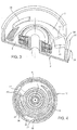
- FIGS 5 to 7 illustrate a tensioner 50 that differs from the described tensioner 1 mainly in a different embodiment of the damping device, in this case indicated by reference numeral 51.
- the damping device 51 still comprises a bushing 35 made of a plastic material and a blade spring 36; the latter comprises a shaped end 52 formed by a portion 53 inclined in the axial direction and by an end portion 54 prismatically engaging a slot 55 made in the base plate 6.
- Portion 53 is inclined towards the base plate 6 and has the purpose of connecting end portion 54, arranged at the level of the base plate 6, with the main annular portion of spring 36, placed around spring 5, avoiding interference with the first coil of this spring, which in this case rests directly against a projection 56 of the base plate 6.
- the bushing 35 externally surrounds spring 36, up to and including the opposite axial ends, and is preferably over-pressed on spring 36.
- the damping device 54 is mounted with radial interference inside the outer wall 11 of the connection portion 10 of the arm 3.
- rolling bearings 14 and 15 for the support and alignment of the arm 3 enable achieving a substantially wear-free product, and therefore not subject to replacement for the entire life of the vehicle, and with much lower costs with respect to hydraulic tensioners of the known art.
- the bearings 14 and 15 balance the tilting torques acting on the arm 3 due to the contact between the pulley 4 and the belt, ensuring perfect alignment of the arm throughout the life of the tensioner 1 and preventing the tilting torques from interacting with the damping device and causing a progressive change in the damping provided over time.
- the various functions of the tensioner are performed independently of each other by dedicated members or devices that do not functionally interact with one another.
- the damping device 34 is placed in contact with the outer wall 11.
- this arrangement is advantageous from the heat dissipation viewpoint, it would be possible to place the damping device 34 inside spring 5, in contact with the inner wall 12.
- spring 36 should enclose the bushing 35 from the outside.
Description
- The present invention relates to a belt tensioner for a belt drive, and particularly, but not exclusively, for an accessory drive of an industrial vehicle.
- As is known, tensioners for accessory drives comprise a fixed part configured to be fastened to the engine and defining a rotational pivot, an arm rotatably supported on the rotational pivot and carrying, at one end, a pulley suitable for cooperating with a drive belt and a spring acting on the arm to tension the belt.
- Known tensioners of the above-stated type must meet certain functional requirements aimed at optimizing the life of the tensioner and of the belt. In particular, it is necessary that the arm is kept in perfect alignment, i.e. it rotates on a plane orthogonal to the axis of the pivot and is not subjected to oscillations outside the plane that might result in noise, premature wear and, eventually, belt slippage.
- The alignment function is normally delegated to one or more bushings, made of a plastic or composite material, having the function of a sliding bearing for the radial and axial support of the arm on the pivot.
- These bushings are subject to wear; in consequence, the tensioner has a limited life, in any case shorter than that of the vehicle.
- Hydraulic tensioners have been developed to solve this problem, wherein the force acting on the arm is generated by a hydraulic piston. Since the piston can be oriented to minimize the resultant of the forces acting on the pivot, hydraulic tensioners are normally components not subject to replacement during the life of the vehicle. However, hydraulic tensioners are more complex and expensive than conventional mechanical tensioners.
-
EP0425246 A1 discloses a tensioner according to the preamble ofclaim 1. - The object of the present invention is to provide a mechanical tensioner that overcomes the above-described problems of the known art.
- The above-stated object is achieved by a tensioner according to
claim 1. - For a better understanding of the present invention, a preferred embodiment is described below by way of non-limitative example and with reference to the accompanying drawings, where:
-
Figure 1 is an exploded perspective view of a tensioner according to the present invention; -
Figure 2 is a cross-section of the tensioner along a median plane of the arm; -
Figure 3 is a partial perspective view of a fixed part of the tensioner inFigures 1 and2 ; -
Figure 4 is a cross-section along line IV-IV inFigure 1 ; -
Figure 5 is an exploded perspective view of a second embodiment of a tensioner according to the present invention; -
Figure 6 is a cross-section of the tensioner along a median plane of the arm; and -
Figure 7 is an exploded perspective view, on an enlarged scale, of a damping device of the tensioner inFigure 5 . - With reference to the figures, a tensioner for an accessory drive of an industrial vehicle in indicated, as a whole, by
reference numeral 1. - The tensioner basically comprises a
fixed part 2 suitable for being fastened to the engine, anarm 3 that is rotatable with respect to thefixed part 2 about an axis A, apulley 4 rotatably carried by thearm 3 and suitable for cooperating with a belt (not shown) and aspring 5 constrained to thefixed part 2 and to thearm 3 to exert an elastic load on the latter such as to push thepulley 4 into contact with the belt. - More specifically, the
fixed part 2 comprises abase plate 6 suitable for resting on a surface of the engine and a hollow, substantiallycylindrical pivot 7, aligned along axis A, embedded in a central hole 8 of thebase plate 6 and projecting from the latter. - The
fixed part 2 can be fastened to the engine by ascrew 9 that passes through thepivot 7. - The
arm 3 includes a hollow, substantiallycylindrical connection portion 10, comprising anouter wall 11 and aninner wall 12, forming between them acavity 13 open towards thebase plate 6, which is at least partially housed inside a front edge of theouter wall 11. - The
arm 3 is supported on thefixed part 2 by a pair ofrolling bearings inner wall 12 of theconnection portion 10 of thearm 3 and thepivot 7. Each one of thebearings pivot 7 and anouter race 17 embedded on theinner wall 12. - The
bearings outer race 17 of bearing 15 axially abuts against theinner shoulder 18 of theinner wall 12. The inner race 16 of bearing 14 axially abuts against anannular shoulder 19 of thebase plate 6 surrounding thepivot 7. - The
bearings arm 3 due to the contact between thepulley 4 and the belt, ensuring perfect alignment of the arm throughout the life of thetensioner 1. - Conveniently, a dust-
protection ring 20 is mounted between the inner race 16 of thebearing 15 and anend shoulder 24 of thepivot 7, upon which thehead 25 of thescrew 9 acts. Thering 20 conveniently comprises anouter rim 26 axially folded in the direction opposite to thebearing 15, which engages, with play, anannular cavity 27 formed between theinner wall 12 and aninner projection 28 of the 12, so as to form a labyrinth seal. - The
spring 5 is housed insidecavity 13 and has afirst end coil 29 constrained to thefixed part 2 as described hereinafter, and asecond end coil 30 constrained toarm 3 in a conventional manner. - The
tensioner 1 also comprises adamping device 34 suitable for damping the relative oscillations between thearm 3 and thefixed part 2. Thedamping device 34 is arranged overlapping thebearings damping device 34 comprises an open C-shapedcylindrical bushing 35, made of a plastic material, housed incavity 13 in contact with theouter wall 11, and ablade spring 36, of similar shape, housed inside thebushing 35 in a forced manner, so as to exert an elastic load on the bushing and keep it in contact with theouter wall 11 in a forced manner. - The
bushing 35 and thespring 36 haverespective notches projection 39 extending from thebase plate 6 and are therefore rotationally locked.Projection 39 also functions as a rest for thespring 5. - At one end, the
spring 36 has aportion 40 folded radially inwards, which rests against afurther projection 41 of thebase plate 6 and acts as a stop for the end of thefirst coil 29 of thespring 5. - The
pulley 4 is rotatably mounted on anend 42 of thearm 3 opposite to theconnection portion 10 in a conventional manner that is not shown. - The operation of the
tensioner 1 is as follows. - The
arm 3 is supported on thepivot 7 by thebearings arm 3 takes place parallel to a plane perpendicular to axis A. As rolling bearings are used, their wear is negligible and the alignment of the arm is therefore assured for the entire life of the vehicle. The damping function is provided bydevice 34, which behaves asymmetrically: when thearm 3 turns in a first direction towards the belt, the friction contact between theouter wall 11 and thebushing 35 tends to radially contract thespring 36, reducing the contact pressure and consequently the damping. Vice versa, when thearm 3 turns in the opposite direction, thespring 36 tends to expand, increasing the contact pressure between theouter wall 11 and thebushing 35. -
Figures 5 to 7 illustrate atensioner 50 that differs from the describedtensioner 1 mainly in a different embodiment of the damping device, in this case indicated byreference numeral 51. - The
damping device 51 still comprises a bushing 35 made of a plastic material and ablade spring 36; the latter comprises ashaped end 52 formed by aportion 53 inclined in the axial direction and by anend portion 54 prismatically engaging aslot 55 made in thebase plate 6.Portion 53 is inclined towards thebase plate 6 and has the purpose of connectingend portion 54, arranged at the level of thebase plate 6, with the main annular portion ofspring 36, placed aroundspring 5, avoiding interference with the first coil of this spring, which in this case rests directly against aprojection 56 of thebase plate 6. - The bushing 35 externally surrounds
spring 36, up to and including the opposite axial ends, and is preferably over-pressed onspring 36. - The
damping device 54 is mounted with radial interference inside theouter wall 11 of theconnection portion 10 of thearm 3. - From examination of the characteristics of the
tensioner 1 provided according to the present invention, the advantages that may be achieved therewith are evident. - The use of
rolling bearings arm 3 enable achieving a substantially wear-free product, and therefore not subject to replacement for the entire life of the vehicle, and with much lower costs with respect to hydraulic tensioners of the known art. - The
bearings arm 3 due to the contact between thepulley 4 and the belt, ensuring perfect alignment of the arm throughout the life of thetensioner 1 and preventing the tilting torques from interacting with the damping device and causing a progressive change in the damping provided over time. - The various functions of the tensioner (tensioning of the belt via the
spring 5, support of the arm via thebearings damping device 34 is placed in contact with theouter wall 11. Although this arrangement is advantageous from the heat dissipation viewpoint, it would be possible to place thedamping device 34 insidespring 5, in contact with theinner wall 12. Obviously, in thiscase spring 36 should enclose thebushing 35 from the outside. - Furthermore, it is possible to use a radial or axial action symmetric damping device in addition to or as a replacement for the described
asymmetric damping device 34.
Claims (11)
- A belt tensioner for a belt drive of a motor vehicle engine, comprising:- a fixed part (2) configured to be fixed with respect to the engine and provided with a pivot (7) defining a rotation axis (A) ;- an arm (3) having a connection portion (10) hinged to the pivot (7) and rotatable about the rotation axis (A) and an opposite portion (42) rotatably supporting a pulley (4) configured to cooperate with a belt of the drive;- a main spring (5) interposed between the fixed part (2) and the arm (3) to exert thrust on said arm (3) such as to rotate said arm towards the belt; and- at least one support member (14, 15) interposed between the arm (3) and the pivot (7), said support member (14, 15) including at least one rolling bearing;characterized by comprising a damping device (34) for damping oscillations of the arm (3) with respect to the fixed part (2) arranged at least partially overlapping said at least one rolling bearing (14, 15) in a radial direction, said at least one rolling bearing (14, 15) supports the tilting loads on the arm (3), preventing said loads from interfering with said damping device (34).
- A tensioner according to claim 1, characterized by comprising two support members (14, 15) constituted by respective ball bearings interposed between the connection portion (10) and said pivot (7).
- A tensioner according to claim 2, characterized in that the connection portion (10) comprises an outer cylindrical wall (11) and an inner cylindrical wall (12) delimiting between them an annular cavity (13) housing said main spring (5), said bearings (14, 15) being radially set between said pivot (7) and said inner cylindrical wall (12).
- A tensioner according to claim 1, characterized in that said damping device (34) acts radially.
- A tensioner according to any of the preceding claims, characterized in that said damping device (34) has a damping intensity dependent on the direction of rotation of the arm (3).
- A tensioner according to any of the preceding claims, characterized in that the damping device (34) comprises a bushing (35) rotationally integral with one of the fixed part(2) and the connection portion (10) of the arm (3), and a cylindrical surface (11) carried by the other of the fixed part (2) and the connection portion (10) of the arm (3), said bushing (35) cooperating in an interference-fitted manner with said cylindrical surface (11).
- A tensioner according to claim 6, characterized in that said bushing (35) has an open C-shape and in that said damping device (34) comprises a C-shaped blade spring (36) exerting a radial load on said bushing (35) to force it against said cylindrical surface (11).
- A tensioner according to claim 6 or 7, characterized in that said fixed part (2) comprises a base plate (6) to which said pivot (7) is fastened, said bushing (35) and said blade spring (36) being anchored to said base plate (6).
- A tensioner according to claim 8, characterized in that said base plate (6) has a first projection (39) for anchoring said bushing (35) and said blade spring (36) to said fixed part (2), and a second projection (40) for constraining one end of said main spring (5) to said fixed part (2).
- A tensioner according to claim 8, characterized in that said base plate (6) comprises a projection (56) for constraining one end of said main spring (5) to said fixed part (2) and a slot (55) prismatically engaged by an end portion (54) of the blade spring (36).
- A tensioner according to claim 9 or 10, characterized by comprising a dust-protection ring (20) interposed between one of the bearings (15) and a shoulder (24) of the pivot (7) and forming a labyrinth seal with a cavity (27) of the connection portion (10).
Applications Claiming Priority (2)
| Application Number | Priority Date | Filing Date | Title |
|---|---|---|---|
| IT001032A ITTO20131032A1 (en) | 2013-12-17 | 2013-12-17 | TENSIONER FOR A BELT DRIVE |
| PCT/IB2014/067040 WO2015092718A1 (en) | 2013-12-17 | 2014-12-17 | A belt tensioner for a belt drive |
Publications (2)
| Publication Number | Publication Date |
|---|---|
| EP3084264A1 EP3084264A1 (en) | 2016-10-26 |
| EP3084264B1 true EP3084264B1 (en) | 2019-09-18 |
Family
ID=50190601
Family Applications (1)
| Application Number | Title | Priority Date | Filing Date |
|---|---|---|---|
| EP14830701.0A Active EP3084264B1 (en) | 2013-12-17 | 2014-12-17 | A belt tensioner for a belt drive |
Country Status (7)
| Country | Link |
|---|---|
| US (1) | US10718410B2 (en) |
| EP (1) | EP3084264B1 (en) |
| JP (1) | JP6510530B2 (en) |
| CN (1) | CN105829764B (en) |
| BR (1) | BR112016013978B1 (en) |
| IT (1) | ITTO20131032A1 (en) |
| WO (1) | WO2015092718A1 (en) |
Families Citing this family (4)
| Publication number | Priority date | Publication date | Assignee | Title |
|---|---|---|---|---|
| IT201900011160A1 (en) * | 2019-07-08 | 2021-01-08 | Dayco Europe Srl | TENSIONER FOR AN ACCESSORY TRANSMISSION OF AN INTERNAL COMBUSTION ENGINE |
| US11333223B2 (en) * | 2019-08-06 | 2022-05-17 | Gates Corporation | Orbital tensioner |
| CN113819174B (en) * | 2021-09-22 | 2023-02-10 | 安徽恒均粉末冶金科技股份有限公司 | Damping block for belt tensioner spring based on powder metallurgy technology and preparation method |
| CA3236871A1 (en) * | 2021-10-29 | 2023-05-04 | Gates Corporation | Bearing pivot tensioner assembly |
Family Cites Families (36)
| Publication number | Priority date | Publication date | Assignee | Title |
|---|---|---|---|---|
| US4725260A (en) * | 1987-03-24 | 1988-02-16 | Litens Automotive Inc. | Belt tensioner with spring actuated band brake damping |
| JPH0445A (en) * | 1989-10-23 | 1992-01-06 | Mitsuboshi Belting Ltd | Auto-tensioner |
| US5083983A (en) * | 1989-10-23 | 1992-01-28 | Mitsuboshi Belting Ltd. | Belt tensioner |
| JPH0530595U (en) | 1991-09-30 | 1993-04-23 | 三ツ星ベルト株式会社 | Auto tensioner |
| JP3195867B2 (en) * | 1993-10-05 | 2001-08-06 | バンドー化学株式会社 | Auto tensioner |
| JP2981415B2 (en) * | 1995-06-14 | 1999-11-22 | ユニッタ株式会社 | Belt tensioner |
| US5803849A (en) * | 1995-06-14 | 1998-09-08 | Unitta Company | Belt tensioner |
| DE19926615A1 (en) * | 1999-06-11 | 2000-12-14 | Schaeffler Waelzlager Ohg | Tensioning device for traction devices such as belts or chains |
| JP2002039297A (en) * | 2000-07-19 | 2002-02-06 | Unitta Co Ltd | Auto-tensioner |
| JP2002130402A (en) * | 2000-10-27 | 2002-05-09 | Koyo Seiko Co Ltd | Automatic tensioner |
| US7588507B2 (en) * | 2001-04-13 | 2009-09-15 | Unitta Company | Thin autotensioner |
| US6609988B1 (en) * | 2001-05-24 | 2003-08-26 | The Gates Corporation | Asymmetric damping tensioner belt drive system |
| US7004863B2 (en) * | 2002-05-15 | 2006-02-28 | The Gates Corporation | Damping mechanism |
| BR8202522U (en) | 2002-07-15 | 2004-06-01 | Ivan Gondim Leichsenring | Unpredictably keyboard |
| DE10338530A1 (en) | 2003-08-19 | 2005-03-17 | Ina-Schaeffler Kg | seal |
| DE102004047422A1 (en) * | 2004-09-28 | 2006-04-13 | Muhr Und Bender Kg | Belt tensioning device with high damping |
| JP4949376B2 (en) * | 2005-03-21 | 2012-06-06 | ライテンズ オートモーティブ パートナーシップ | Belt tensioner with wear compensation |
| WO2006111988A1 (en) * | 2005-04-20 | 2006-10-26 | Dayco Europe S.R.L. Con Unico Socio | Tightener for a belt drive operating in the presence of oil |
| US8075433B2 (en) * | 2005-06-28 | 2011-12-13 | Dayco Products, Llc | Belt tensioner with damping member |
| DE102005057297A1 (en) * | 2005-12-01 | 2007-06-21 | Schaeffler Kg | Deflection pulley for a traction device |
| KR101322173B1 (en) * | 2006-03-22 | 2013-10-25 | 리텐스 오토모티브 파트너쉽 | Tensioner for flexible drives |
| DE102006014942A1 (en) * | 2006-03-31 | 2007-10-04 | Schaeffler Kg | Clamping device for use in traction mechanism drive, has coil spring, where tilting moment of spring force of spring and resultant reaction force of drive mutually suspend rotary axis of swivel bearing around imaginary slide tilting axis |
| DE102006017287B4 (en) * | 2006-04-12 | 2021-03-25 | Litens Automotive Gmbh | Tensioner for an endless drive |
| JP4922667B2 (en) * | 2006-05-30 | 2012-04-25 | 日産自動車株式会社 | Tensioner |
| US8038555B2 (en) * | 2006-08-31 | 2011-10-18 | Dayco Products, Llc | One-way clutched damper for automatic belt tensioner |
| DE102006042105A1 (en) * | 2006-09-07 | 2008-03-27 | Schaeffler Kg | Clamping device for a traction mechanism drive |
| ATE520900T1 (en) * | 2007-05-01 | 2011-09-15 | Litens Automotive Inc | TENSIONER WITH WEAR COMPENSATION |
| DE102007039133A1 (en) * | 2007-08-18 | 2009-02-19 | Schaeffler Kg | tensioner |
| DE102008050384A1 (en) * | 2008-10-02 | 2010-04-08 | Schaeffler Kg | Clamping and damping device for traction drives |
| PL2331844T3 (en) * | 2008-10-02 | 2014-05-30 | Litens Automotive Inc | Compact tensioner with sustainable damping |
| JP5276520B2 (en) * | 2008-10-10 | 2013-08-28 | 智和 石田 | Auto tensioner |
| US20110177897A1 (en) | 2010-01-20 | 2011-07-21 | Peter Ward | Tensioner |
| US8613680B2 (en) * | 2010-04-20 | 2013-12-24 | Litens Automotive Partnership | Tensioner with spring damper |
| US8439781B2 (en) * | 2010-06-22 | 2013-05-14 | Dayco Ip Holdings, Llc | Radial damping mechanism and use for belt tensioning |
| US9212731B2 (en) * | 2013-07-26 | 2015-12-15 | Dayco Ip Holdings, Llc | Tensioner with multiple nested torsion springs |
| EP2955414A1 (en) * | 2014-06-13 | 2015-12-16 | Aktiebolaget SKF | Tensioning device and method for assembling such a tensioning device |
-
2013
- 2013-12-17 IT IT001032A patent/ITTO20131032A1/en unknown
-
2014
- 2014-12-17 CN CN201480069040.XA patent/CN105829764B/en active Active
- 2014-12-17 BR BR112016013978-0A patent/BR112016013978B1/en active IP Right Grant
- 2014-12-17 WO PCT/IB2014/067040 patent/WO2015092718A1/en active Application Filing
- 2014-12-17 EP EP14830701.0A patent/EP3084264B1/en active Active
- 2014-12-17 US US15/104,646 patent/US10718410B2/en active Active
- 2014-12-17 JP JP2016540654A patent/JP6510530B2/en active Active
Non-Patent Citations (1)
| Title |
|---|
| None * |
Also Published As
| Publication number | Publication date |
|---|---|
| BR112016013978A2 (en) | 2017-08-08 |
| JP6510530B2 (en) | 2019-05-08 |
| CN105829764B (en) | 2021-02-12 |
| US20170002902A1 (en) | 2017-01-05 |
| JP2016540945A (en) | 2016-12-28 |
| BR112016013978B1 (en) | 2022-04-12 |
| EP3084264A1 (en) | 2016-10-26 |
| WO2015092718A1 (en) | 2015-06-25 |
| US10718410B2 (en) | 2020-07-21 |
| ITTO20131032A1 (en) | 2015-06-18 |
| CN105829764A (en) | 2016-08-03 |
Similar Documents
| Publication | Publication Date | Title |
|---|---|---|
| EP3084264B1 (en) | A belt tensioner for a belt drive | |
| US4551120A (en) | Belt tensioner | |
| KR101601385B1 (en) | Tensioner with expanding spring for radial frictional asymmetric damping | |
| JP2010529380A (en) | Pulley tensioner for oil lubrication belt drive | |
| JPH09189347A (en) | Tensioner furnished with damping mechanism | |
| EP2971855B1 (en) | Tensioner with expanding spring for radial frictional asymmetric damping | |
| JPH0861444A (en) | Belt tension device with sliding bearing ring with rib | |
| US11913549B2 (en) | Tensioner for an accessory transmission of an internal combustion engine | |
| CN103288016B (en) | Tensioning device for a traction element and method of installation of such a device | |
| JP2011140972A (en) | Tension adjusting device of wrapping transmission member in wrapping transmission device | |
| CN109690134B (en) | V-shaped tensioner and annular transmission device | |
| US4051739A (en) | Drive clutch for the v-belt type automatic transmission | |
| JPH04244644A (en) | Auto tensioner | |
| JP6737907B2 (en) | Tensioner | |
| CN107250612B (en) | Tensioner with improved damping device | |
| CN117722474A (en) | Asymmetric high damping ratio tensioner | |
| JP2016151288A (en) | Electric actuator and v-belt type continuously variable transmission using the same | |
| JP5986965B2 (en) | Tensioner | |
| KR20090115506A (en) | Tention Pulley Device | |
| KR20200076253A (en) | Auto tensioner for vehicle | |
| JP2006138433A (en) | Automatic tensioner | |
| JP2015224741A (en) | Auto tensioner |
Legal Events
| Date | Code | Title | Description |
|---|---|---|---|
| PUAI | Public reference made under article 153(3) epc to a published international application that has entered the european phase |
Free format text: ORIGINAL CODE: 0009012 |
|
| 17P | Request for examination filed |
Effective date: 20160620 |
|
| AK | Designated contracting states |
Kind code of ref document: A1 Designated state(s): AL AT BE BG CH CY CZ DE DK EE ES FI FR GB GR HR HU IE IS IT LI LT LU LV MC MK MT NL NO PL PT RO RS SE SI SK SM TR |
|
| AX | Request for extension of the european patent |
Extension state: BA ME |
|
| DAX | Request for extension of the european patent (deleted) | ||
| STAA | Information on the status of an ep patent application or granted ep patent |
Free format text: STATUS: EXAMINATION IS IN PROGRESS |
|
| 17Q | First examination report despatched |
Effective date: 20181205 |
|
| GRAP | Despatch of communication of intention to grant a patent |
Free format text: ORIGINAL CODE: EPIDOSNIGR1 |
|
| STAA | Information on the status of an ep patent application or granted ep patent |
Free format text: STATUS: GRANT OF PATENT IS INTENDED |
|
| INTG | Intention to grant announced |
Effective date: 20190410 |
|
| GRAS | Grant fee paid |
Free format text: ORIGINAL CODE: EPIDOSNIGR3 |
|
| GRAA | (expected) grant |
Free format text: ORIGINAL CODE: 0009210 |
|
| STAA | Information on the status of an ep patent application or granted ep patent |
Free format text: STATUS: THE PATENT HAS BEEN GRANTED |
|
| AK | Designated contracting states |
Kind code of ref document: B1 Designated state(s): AL AT BE BG CH CY CZ DE DK EE ES FI FR GB GR HR HU IE IS IT LI LT LU LV MC MK MT NL NO PL PT RO RS SE SI SK SM TR |
|
| REG | Reference to a national code |
Ref country code: GB Ref legal event code: FG4D |
|
| REG | Reference to a national code |
Ref country code: CH Ref legal event code: EP |
|
| REG | Reference to a national code |
Ref country code: DE Ref legal event code: R096 Ref document number: 602014053986 Country of ref document: DE |
|
| REG | Reference to a national code |
Ref country code: AT Ref legal event code: REF Ref document number: 1181698 Country of ref document: AT Kind code of ref document: T Effective date: 20191015 |
|
| REG | Reference to a national code |
Ref country code: IE Ref legal event code: FG4D |
|
| REG | Reference to a national code |
Ref country code: NL Ref legal event code: MP Effective date: 20190918 |
|
| PG25 | Lapsed in a contracting state [announced via postgrant information from national office to epo] |
Ref country code: SE Free format text: LAPSE BECAUSE OF FAILURE TO SUBMIT A TRANSLATION OF THE DESCRIPTION OR TO PAY THE FEE WITHIN THE PRESCRIBED TIME-LIMIT Effective date: 20190918 Ref country code: BG Free format text: LAPSE BECAUSE OF FAILURE TO SUBMIT A TRANSLATION OF THE DESCRIPTION OR TO PAY THE FEE WITHIN THE PRESCRIBED TIME-LIMIT Effective date: 20191218 Ref country code: HR Free format text: LAPSE BECAUSE OF FAILURE TO SUBMIT A TRANSLATION OF THE DESCRIPTION OR TO PAY THE FEE WITHIN THE PRESCRIBED TIME-LIMIT Effective date: 20190918 Ref country code: FI Free format text: LAPSE BECAUSE OF FAILURE TO SUBMIT A TRANSLATION OF THE DESCRIPTION OR TO PAY THE FEE WITHIN THE PRESCRIBED TIME-LIMIT Effective date: 20190918 Ref country code: NO Free format text: LAPSE BECAUSE OF FAILURE TO SUBMIT A TRANSLATION OF THE DESCRIPTION OR TO PAY THE FEE WITHIN THE PRESCRIBED TIME-LIMIT Effective date: 20191218 Ref country code: LT Free format text: LAPSE BECAUSE OF FAILURE TO SUBMIT A TRANSLATION OF THE DESCRIPTION OR TO PAY THE FEE WITHIN THE PRESCRIBED TIME-LIMIT Effective date: 20190918 |
|
| REG | Reference to a national code |
Ref country code: LT Ref legal event code: MG4D |
|
| PG25 | Lapsed in a contracting state [announced via postgrant information from national office to epo] |
Ref country code: LV Free format text: LAPSE BECAUSE OF FAILURE TO SUBMIT A TRANSLATION OF THE DESCRIPTION OR TO PAY THE FEE WITHIN THE PRESCRIBED TIME-LIMIT Effective date: 20190918 Ref country code: GR Free format text: LAPSE BECAUSE OF FAILURE TO SUBMIT A TRANSLATION OF THE DESCRIPTION OR TO PAY THE FEE WITHIN THE PRESCRIBED TIME-LIMIT Effective date: 20191219 Ref country code: RS Free format text: LAPSE BECAUSE OF FAILURE TO SUBMIT A TRANSLATION OF THE DESCRIPTION OR TO PAY THE FEE WITHIN THE PRESCRIBED TIME-LIMIT Effective date: 20190918 Ref country code: AL Free format text: LAPSE BECAUSE OF FAILURE TO SUBMIT A TRANSLATION OF THE DESCRIPTION OR TO PAY THE FEE WITHIN THE PRESCRIBED TIME-LIMIT Effective date: 20190918 |
|
| REG | Reference to a national code |
Ref country code: AT Ref legal event code: MK05 Ref document number: 1181698 Country of ref document: AT Kind code of ref document: T Effective date: 20190918 |
|
| PG25 | Lapsed in a contracting state [announced via postgrant information from national office to epo] |
Ref country code: ES Free format text: LAPSE BECAUSE OF FAILURE TO SUBMIT A TRANSLATION OF THE DESCRIPTION OR TO PAY THE FEE WITHIN THE PRESCRIBED TIME-LIMIT Effective date: 20190918 Ref country code: PT Free format text: LAPSE BECAUSE OF FAILURE TO SUBMIT A TRANSLATION OF THE DESCRIPTION OR TO PAY THE FEE WITHIN THE PRESCRIBED TIME-LIMIT Effective date: 20200120 Ref country code: PL Free format text: LAPSE BECAUSE OF FAILURE TO SUBMIT A TRANSLATION OF THE DESCRIPTION OR TO PAY THE FEE WITHIN THE PRESCRIBED TIME-LIMIT Effective date: 20190918 Ref country code: RO Free format text: LAPSE BECAUSE OF FAILURE TO SUBMIT A TRANSLATION OF THE DESCRIPTION OR TO PAY THE FEE WITHIN THE PRESCRIBED TIME-LIMIT Effective date: 20190918 Ref country code: NL Free format text: LAPSE BECAUSE OF FAILURE TO SUBMIT A TRANSLATION OF THE DESCRIPTION OR TO PAY THE FEE WITHIN THE PRESCRIBED TIME-LIMIT Effective date: 20190918 Ref country code: IT Free format text: LAPSE BECAUSE OF FAILURE TO SUBMIT A TRANSLATION OF THE DESCRIPTION OR TO PAY THE FEE WITHIN THE PRESCRIBED TIME-LIMIT Effective date: 20190918 Ref country code: AT Free format text: LAPSE BECAUSE OF FAILURE TO SUBMIT A TRANSLATION OF THE DESCRIPTION OR TO PAY THE FEE WITHIN THE PRESCRIBED TIME-LIMIT Effective date: 20190918 Ref country code: EE Free format text: LAPSE BECAUSE OF FAILURE TO SUBMIT A TRANSLATION OF THE DESCRIPTION OR TO PAY THE FEE WITHIN THE PRESCRIBED TIME-LIMIT Effective date: 20190918 |
|
| PG25 | Lapsed in a contracting state [announced via postgrant information from national office to epo] |
Ref country code: IS Free format text: LAPSE BECAUSE OF FAILURE TO SUBMIT A TRANSLATION OF THE DESCRIPTION OR TO PAY THE FEE WITHIN THE PRESCRIBED TIME-LIMIT Effective date: 20200224 Ref country code: SM Free format text: LAPSE BECAUSE OF FAILURE TO SUBMIT A TRANSLATION OF THE DESCRIPTION OR TO PAY THE FEE WITHIN THE PRESCRIBED TIME-LIMIT Effective date: 20190918 Ref country code: CZ Free format text: LAPSE BECAUSE OF FAILURE TO SUBMIT A TRANSLATION OF THE DESCRIPTION OR TO PAY THE FEE WITHIN THE PRESCRIBED TIME-LIMIT Effective date: 20190918 Ref country code: SK Free format text: LAPSE BECAUSE OF FAILURE TO SUBMIT A TRANSLATION OF THE DESCRIPTION OR TO PAY THE FEE WITHIN THE PRESCRIBED TIME-LIMIT Effective date: 20190918 |
|
| REG | Reference to a national code |
Ref country code: DE Ref legal event code: R097 Ref document number: 602014053986 Country of ref document: DE |
|
| PLBE | No opposition filed within time limit |
Free format text: ORIGINAL CODE: 0009261 |
|
| STAA | Information on the status of an ep patent application or granted ep patent |
Free format text: STATUS: NO OPPOSITION FILED WITHIN TIME LIMIT |
|
| PG2D | Information on lapse in contracting state deleted |
Ref country code: IS |
|
| PG25 | Lapsed in a contracting state [announced via postgrant information from national office to epo] |
Ref country code: DK Free format text: LAPSE BECAUSE OF FAILURE TO SUBMIT A TRANSLATION OF THE DESCRIPTION OR TO PAY THE FEE WITHIN THE PRESCRIBED TIME-LIMIT Effective date: 20190918 Ref country code: IS Free format text: LAPSE BECAUSE OF FAILURE TO SUBMIT A TRANSLATION OF THE DESCRIPTION OR TO PAY THE FEE WITHIN THE PRESCRIBED TIME-LIMIT Effective date: 20200119 |
|
| REG | Reference to a national code |
Ref country code: CH Ref legal event code: PL |
|
| 26N | No opposition filed |
Effective date: 20200619 |
|
| REG | Reference to a national code |
Ref country code: BE Ref legal event code: MM Effective date: 20191231 |
|
| PG25 | Lapsed in a contracting state [announced via postgrant information from national office to epo] |
Ref country code: MC Free format text: LAPSE BECAUSE OF FAILURE TO SUBMIT A TRANSLATION OF THE DESCRIPTION OR TO PAY THE FEE WITHIN THE PRESCRIBED TIME-LIMIT Effective date: 20190918 Ref country code: SI Free format text: LAPSE BECAUSE OF FAILURE TO SUBMIT A TRANSLATION OF THE DESCRIPTION OR TO PAY THE FEE WITHIN THE PRESCRIBED TIME-LIMIT Effective date: 20190918 |
|
| GBPC | Gb: european patent ceased through non-payment of renewal fee |
Effective date: 20191218 |
|
| PG25 | Lapsed in a contracting state [announced via postgrant information from national office to epo] |
Ref country code: LU Free format text: LAPSE BECAUSE OF NON-PAYMENT OF DUE FEES Effective date: 20191217 Ref country code: FR Free format text: LAPSE BECAUSE OF NON-PAYMENT OF DUE FEES Effective date: 20191231 Ref country code: IE Free format text: LAPSE BECAUSE OF NON-PAYMENT OF DUE FEES Effective date: 20191217 Ref country code: GB Free format text: LAPSE BECAUSE OF NON-PAYMENT OF DUE FEES Effective date: 20191218 |
|
| PG25 | Lapsed in a contracting state [announced via postgrant information from national office to epo] |
Ref country code: BE Free format text: LAPSE BECAUSE OF NON-PAYMENT OF DUE FEES Effective date: 20191231 Ref country code: LI Free format text: LAPSE BECAUSE OF NON-PAYMENT OF DUE FEES Effective date: 20191231 Ref country code: CH Free format text: LAPSE BECAUSE OF NON-PAYMENT OF DUE FEES Effective date: 20191231 |
|
| PG25 | Lapsed in a contracting state [announced via postgrant information from national office to epo] |
Ref country code: CY Free format text: LAPSE BECAUSE OF FAILURE TO SUBMIT A TRANSLATION OF THE DESCRIPTION OR TO PAY THE FEE WITHIN THE PRESCRIBED TIME-LIMIT Effective date: 20190918 |
|
| PG25 | Lapsed in a contracting state [announced via postgrant information from national office to epo] |
Ref country code: HU Free format text: LAPSE BECAUSE OF FAILURE TO SUBMIT A TRANSLATION OF THE DESCRIPTION OR TO PAY THE FEE WITHIN THE PRESCRIBED TIME-LIMIT; INVALID AB INITIO Effective date: 20141217 Ref country code: MT Free format text: LAPSE BECAUSE OF FAILURE TO SUBMIT A TRANSLATION OF THE DESCRIPTION OR TO PAY THE FEE WITHIN THE PRESCRIBED TIME-LIMIT Effective date: 20190918 |
|
| PG25 | Lapsed in a contracting state [announced via postgrant information from national office to epo] |
Ref country code: TR Free format text: LAPSE BECAUSE OF FAILURE TO SUBMIT A TRANSLATION OF THE DESCRIPTION OR TO PAY THE FEE WITHIN THE PRESCRIBED TIME-LIMIT Effective date: 20190918 |
|
| PG25 | Lapsed in a contracting state [announced via postgrant information from national office to epo] |
Ref country code: MK Free format text: LAPSE BECAUSE OF FAILURE TO SUBMIT A TRANSLATION OF THE DESCRIPTION OR TO PAY THE FEE WITHIN THE PRESCRIBED TIME-LIMIT Effective date: 20190918 |
|
| P01 | Opt-out of the competence of the unified patent court (upc) registered |
Effective date: 20230505 |
|
| REG | Reference to a national code |
Ref country code: DE Ref legal event code: R081 Ref document number: 602014053986 Country of ref document: DE Owner name: PROPULSION SOLUTIONS S.R.L., IVREA, IT Free format text: FORMER OWNER: DAYCO EUROPE S.R.L. CON UNICO SOCIO, CHIETI, IT |
|
| PGFP | Annual fee paid to national office [announced via postgrant information from national office to epo] |
Ref country code: DE Payment date: 20231227 Year of fee payment: 10 |