EP3083027B1 - Vessel for separating components of a reaction mixture obtained by high-pressure polymerization of ethylenically unsaturated monomers with integrated bursting discs - Google Patents
Vessel for separating components of a reaction mixture obtained by high-pressure polymerization of ethylenically unsaturated monomers with integrated bursting discs Download PDFInfo
- Publication number
- EP3083027B1 EP3083027B1 EP14812492.8A EP14812492A EP3083027B1 EP 3083027 B1 EP3083027 B1 EP 3083027B1 EP 14812492 A EP14812492 A EP 14812492A EP 3083027 B1 EP3083027 B1 EP 3083027B1
- Authority
- EP
- European Patent Office
- Prior art keywords
- separation vessel
- separation
- vessel
- mpa
- pressure
- Prior art date
- Legal status (The legal status is an assumption and is not a legal conclusion. Google has not performed a legal analysis and makes no representation as to the accuracy of the status listed.)
- Active
Links
- 230000009172 bursting Effects 0.000 title claims description 69
- 238000006116 polymerization reaction Methods 0.000 title claims description 58
- 239000011541 reaction mixture Substances 0.000 title claims description 34
- 239000000178 monomer Substances 0.000 title claims description 30
- 238000000926 separation method Methods 0.000 claims description 189
- 239000000203 mixture Substances 0.000 claims description 34
- 239000007788 liquid Substances 0.000 claims description 33
- VGGSQFUCUMXWEO-UHFFFAOYSA-N Ethene Chemical compound C=C VGGSQFUCUMXWEO-UHFFFAOYSA-N 0.000 claims description 27
- 239000005977 Ethylene Substances 0.000 claims description 27
- 238000000034 method Methods 0.000 claims description 13
- 239000007870 radical polymerization initiator Substances 0.000 claims description 9
- 238000010526 radical polymerization reaction Methods 0.000 claims description 9
- 229920001519 homopolymer Polymers 0.000 claims description 7
- 229920001577 copolymer Polymers 0.000 claims description 5
- 238000004519 manufacturing process Methods 0.000 claims description 5
- 230000000379 polymerizing effect Effects 0.000 claims description 3
- 239000003999 initiator Substances 0.000 description 31
- 239000007789 gas Substances 0.000 description 29
- 238000006243 chemical reaction Methods 0.000 description 28
- 229920000642 polymer Polymers 0.000 description 12
- 229910000831 Steel Inorganic materials 0.000 description 9
- 238000000746 purification Methods 0.000 description 9
- 239000010959 steel Substances 0.000 description 9
- VXNZUUAINFGPBY-UHFFFAOYSA-N 1-Butene Chemical compound CCC=C VXNZUUAINFGPBY-UHFFFAOYSA-N 0.000 description 8
- LIKMAJRDDDTEIG-UHFFFAOYSA-N 1-hexene Chemical compound CCCCC=C LIKMAJRDDDTEIG-UHFFFAOYSA-N 0.000 description 8
- QQONPFPTGQHPMA-UHFFFAOYSA-N Propene Chemical compound CC=C QQONPFPTGQHPMA-UHFFFAOYSA-N 0.000 description 8
- -1 Polyethylene Polymers 0.000 description 7
- 238000009434 installation Methods 0.000 description 7
- 238000001816 cooling Methods 0.000 description 6
- 229920001684 low density polyethylene Polymers 0.000 description 6
- QVGXLLKOCUKJST-UHFFFAOYSA-N atomic oxygen Chemical compound [O] QVGXLLKOCUKJST-UHFFFAOYSA-N 0.000 description 5
- 239000004702 low-density polyethylene Substances 0.000 description 5
- 239000001301 oxygen Substances 0.000 description 5
- 229910052760 oxygen Inorganic materials 0.000 description 5
- ATUOYWHBWRKTHZ-UHFFFAOYSA-N Propane Chemical compound CCC ATUOYWHBWRKTHZ-UHFFFAOYSA-N 0.000 description 4
- NBBJYMSMWIIQGU-UHFFFAOYSA-N Propionic aldehyde Chemical compound CCC=O NBBJYMSMWIIQGU-UHFFFAOYSA-N 0.000 description 4
- 230000007423 decrease Effects 0.000 description 4
- 150000001451 organic peroxides Chemical class 0.000 description 4
- YWAKXRMUMFPDSH-UHFFFAOYSA-N pentene Chemical compound CCCC=C YWAKXRMUMFPDSH-UHFFFAOYSA-N 0.000 description 4
- 239000012495 reaction gas Substances 0.000 description 4
- XLYOFNOQVPJJNP-UHFFFAOYSA-N water Substances O XLYOFNOQVPJJNP-UHFFFAOYSA-N 0.000 description 4
- NIXOWILDQLNWCW-UHFFFAOYSA-N 2-Propenoic acid Natural products OC(=O)C=C NIXOWILDQLNWCW-UHFFFAOYSA-N 0.000 description 3
- CARSMBZECAABMO-UHFFFAOYSA-N 3-chloro-2,6-dimethylbenzoic acid Chemical compound CC1=CC=C(Cl)C(C)=C1C(O)=O CARSMBZECAABMO-UHFFFAOYSA-N 0.000 description 3
- OKKJLVBELUTLKV-UHFFFAOYSA-N Methanol Chemical compound OC OKKJLVBELUTLKV-UHFFFAOYSA-N 0.000 description 3
- 239000004698 Polyethylene Substances 0.000 description 3
- 230000006835 compression Effects 0.000 description 3
- 238000007906 compression Methods 0.000 description 3
- 238000000354 decomposition reaction Methods 0.000 description 3
- 238000002347 injection Methods 0.000 description 3
- 239000007924 injection Substances 0.000 description 3
- 239000007791 liquid phase Substances 0.000 description 3
- 238000005259 measurement Methods 0.000 description 3
- 239000003607 modifier Substances 0.000 description 3
- VLKZOEOYAKHREP-UHFFFAOYSA-N n-Hexane Chemical compound CCCCCC VLKZOEOYAKHREP-UHFFFAOYSA-N 0.000 description 3
- OFBQJSOFQDEBGM-UHFFFAOYSA-N n-pentane Natural products CCCCC OFBQJSOFQDEBGM-UHFFFAOYSA-N 0.000 description 3
- 238000012354 overpressurization Methods 0.000 description 3
- 229920000573 polyethylene Polymers 0.000 description 3
- 150000003254 radicals Chemical class 0.000 description 3
- 229920006395 saturated elastomer Polymers 0.000 description 3
- 239000002904 solvent Substances 0.000 description 3
- 239000000126 substance Substances 0.000 description 3
- 239000001993 wax Substances 0.000 description 3
- HSLFISVKRDQEBY-UHFFFAOYSA-N 1,1-bis(tert-butylperoxy)cyclohexane Chemical compound CC(C)(C)OOC1(OOC(C)(C)C)CCCCC1 HSLFISVKRDQEBY-UHFFFAOYSA-N 0.000 description 2
- AFFLGGQVNFXPEV-UHFFFAOYSA-N 1-decene Chemical compound CCCCCCCCC=C AFFLGGQVNFXPEV-UHFFFAOYSA-N 0.000 description 2
- KWKAKUADMBZCLK-UHFFFAOYSA-N 1-octene Chemical compound CCCCCCC=C KWKAKUADMBZCLK-UHFFFAOYSA-N 0.000 description 2
- HQOVXPHOJANJBR-UHFFFAOYSA-N 2,2-bis(tert-butylperoxy)butane Chemical compound CC(C)(C)OOC(C)(CC)OOC(C)(C)C HQOVXPHOJANJBR-UHFFFAOYSA-N 0.000 description 2
- ODBCKCWTWALFKM-UHFFFAOYSA-N 2,5-bis(tert-butylperoxy)-2,5-dimethylhex-3-yne Chemical compound CC(C)(C)OOC(C)(C)C#CC(C)(C)OOC(C)(C)C ODBCKCWTWALFKM-UHFFFAOYSA-N 0.000 description 2
- OZAIFHULBGXAKX-UHFFFAOYSA-N 2-(2-cyanopropan-2-yldiazenyl)-2-methylpropanenitrile Chemical compound N#CC(C)(C)N=NC(C)(C)C#N OZAIFHULBGXAKX-UHFFFAOYSA-N 0.000 description 2
- SMZOUWXMTYCWNB-UHFFFAOYSA-N 2-(2-methoxy-5-methylphenyl)ethanamine Chemical compound COC1=CC=C(C)C=C1CCN SMZOUWXMTYCWNB-UHFFFAOYSA-N 0.000 description 2
- GOXQRTZXKQZDDN-UHFFFAOYSA-N 2-Ethylhexyl acrylate Chemical compound CCCCC(CC)COC(=O)C=C GOXQRTZXKQZDDN-UHFFFAOYSA-N 0.000 description 2
- KRDXTHSSNCTAGY-UHFFFAOYSA-N 2-cyclohexylpyrrolidine Chemical compound C1CCNC1C1CCCCC1 KRDXTHSSNCTAGY-UHFFFAOYSA-N 0.000 description 2
- ZACVGCNKGYYQHA-UHFFFAOYSA-N 2-ethylhexoxycarbonyloxy 2-ethylhexyl carbonate Chemical compound CCCCC(CC)COC(=O)OOC(=O)OCC(CC)CCCC ZACVGCNKGYYQHA-UHFFFAOYSA-N 0.000 description 2
- FFWSICBKRCICMR-UHFFFAOYSA-N 5-methyl-2-hexanone Chemical compound CC(C)CCC(C)=O FFWSICBKRCICMR-UHFFFAOYSA-N 0.000 description 2
- IKHGUXGNUITLKF-UHFFFAOYSA-N Acetaldehyde Chemical compound CC=O IKHGUXGNUITLKF-UHFFFAOYSA-N 0.000 description 2
- CSCPPACGZOOCGX-UHFFFAOYSA-N Acetone Chemical compound CC(C)=O CSCPPACGZOOCGX-UHFFFAOYSA-N 0.000 description 2
- SOGAXMICEFXMKE-UHFFFAOYSA-N Butylmethacrylate Chemical compound CCCCOC(=O)C(C)=C SOGAXMICEFXMKE-UHFFFAOYSA-N 0.000 description 2
- LFQSCWFLJHTTHZ-UHFFFAOYSA-N Ethanol Chemical compound CCO LFQSCWFLJHTTHZ-UHFFFAOYSA-N 0.000 description 2
- VZCYOOQTPOCHFL-OWOJBTEDSA-N Fumaric acid Chemical compound OC(=O)\C=C\C(O)=O VZCYOOQTPOCHFL-OWOJBTEDSA-N 0.000 description 2
- KFZMGEQAYNKOFK-UHFFFAOYSA-N Isopropanol Chemical compound CC(C)O KFZMGEQAYNKOFK-UHFFFAOYSA-N 0.000 description 2
- BAPJBEWLBFYGME-UHFFFAOYSA-N Methyl acrylate Chemical compound COC(=O)C=C BAPJBEWLBFYGME-UHFFFAOYSA-N 0.000 description 2
- LRHPLDYGYMQRHN-UHFFFAOYSA-N N-Butanol Chemical compound CCCCO LRHPLDYGYMQRHN-UHFFFAOYSA-N 0.000 description 2
- XTXRWKRVRITETP-UHFFFAOYSA-N Vinyl acetate Chemical compound CC(=O)OC=C XTXRWKRVRITETP-UHFFFAOYSA-N 0.000 description 2
- 150000001338 aliphatic hydrocarbons Chemical class 0.000 description 2
- 125000005603 azodicarboxylic group Chemical group 0.000 description 2
- CQEYYJKEWSMYFG-UHFFFAOYSA-N butyl acrylate Chemical compound CCCCOC(=O)C=C CQEYYJKEWSMYFG-UHFFFAOYSA-N 0.000 description 2
- ZTQSAGDEMFDKMZ-UHFFFAOYSA-N butyric aldehyde Natural products CCCC=O ZTQSAGDEMFDKMZ-UHFFFAOYSA-N 0.000 description 2
- 239000002826 coolant Substances 0.000 description 2
- 238000007334 copolymerization reaction Methods 0.000 description 2
- DIOQZVSQGTUSAI-UHFFFAOYSA-N decane Chemical compound CCCCCCCCCC DIOQZVSQGTUSAI-UHFFFAOYSA-N 0.000 description 2
- LSXWFXONGKSEMY-UHFFFAOYSA-N di-tert-butyl peroxide Chemical compound CC(C)(C)OOC(C)(C)C LSXWFXONGKSEMY-UHFFFAOYSA-N 0.000 description 2
- 229920001038 ethylene copolymer Polymers 0.000 description 2
- 238000010438 heat treatment Methods 0.000 description 2
- 229930195733 hydrocarbon Natural products 0.000 description 2
- 150000002430 hydrocarbons Chemical class 0.000 description 2
- 239000012535 impurity Substances 0.000 description 2
- 230000000977 initiatory effect Effects 0.000 description 2
- 150000002576 ketones Chemical class 0.000 description 2
- 239000000463 material Substances 0.000 description 2
- TVMXDCGIABBOFY-UHFFFAOYSA-N n-Octanol Natural products CCCCCCCC TVMXDCGIABBOFY-UHFFFAOYSA-N 0.000 description 2
- FDPIMTJIUBPUKL-UHFFFAOYSA-N pentan-3-one Chemical compound CCC(=O)CC FDPIMTJIUBPUKL-UHFFFAOYSA-N 0.000 description 2
- 125000000864 peroxy group Chemical group O(O*)* 0.000 description 2
- 229920002959 polymer blend Polymers 0.000 description 2
- 239000003505 polymerization initiator Substances 0.000 description 2
- 238000002360 preparation method Methods 0.000 description 2
- 239000001294 propane Substances 0.000 description 2
- 238000004064 recycling Methods 0.000 description 2
- 230000000630 rising effect Effects 0.000 description 2
- 239000000243 solution Substances 0.000 description 2
- WYKYCHHWIJXDAO-UHFFFAOYSA-N tert-butyl 2-ethylhexaneperoxoate Chemical compound CCCCC(CC)C(=O)OOC(C)(C)C WYKYCHHWIJXDAO-UHFFFAOYSA-N 0.000 description 2
- GJBRNHKUVLOCEB-UHFFFAOYSA-N tert-butyl benzenecarboperoxoate Chemical compound CC(C)(C)OOC(=O)C1=CC=CC=C1 GJBRNHKUVLOCEB-UHFFFAOYSA-N 0.000 description 2
- ISXSCDLOGDJUNJ-UHFFFAOYSA-N tert-butyl prop-2-enoate Chemical compound CC(C)(C)OC(=O)C=C ISXSCDLOGDJUNJ-UHFFFAOYSA-N 0.000 description 2
- CIHOLLKRGTVIJN-UHFFFAOYSA-N tert‐butyl hydroperoxide Chemical compound CC(C)(C)OO CIHOLLKRGTVIJN-UHFFFAOYSA-N 0.000 description 2
- VZCYOOQTPOCHFL-UHFFFAOYSA-N trans-butenedioic acid Natural products OC(=O)C=CC(O)=O VZCYOOQTPOCHFL-UHFFFAOYSA-N 0.000 description 2
- HGXJDMCMYLEZMJ-UHFFFAOYSA-N (2-methylpropan-2-yl)oxy 2,2-dimethylpropaneperoxoate Chemical compound CC(C)(C)OOOC(=O)C(C)(C)C HGXJDMCMYLEZMJ-UHFFFAOYSA-N 0.000 description 1
- KDGNCLDCOVTOCS-UHFFFAOYSA-N (2-methylpropan-2-yl)oxy propan-2-yl carbonate Chemical compound CC(C)OC(=O)OOC(C)(C)C KDGNCLDCOVTOCS-UHFFFAOYSA-N 0.000 description 1
- RQHGZNBWBKINOY-PLNGDYQASA-N (z)-4-tert-butylperoxy-4-oxobut-2-enoic acid Chemical compound CC(C)(C)OOC(=O)\C=C/C(O)=O RQHGZNBWBKINOY-PLNGDYQASA-N 0.000 description 1
- NALFRYPTRXKZPN-UHFFFAOYSA-N 1,1-bis(tert-butylperoxy)-3,3,5-trimethylcyclohexane Chemical compound CC1CC(C)(C)CC(OOC(C)(C)C)(OOC(C)(C)C)C1 NALFRYPTRXKZPN-UHFFFAOYSA-N 0.000 description 1
- ZFFMLCVRJBZUDZ-UHFFFAOYSA-N 2,3-dimethylbutane Chemical class CC(C)C(C)C ZFFMLCVRJBZUDZ-UHFFFAOYSA-N 0.000 description 1
- DMWVYCCGCQPJEA-UHFFFAOYSA-N 2,5-bis(tert-butylperoxy)-2,5-dimethylhexane Chemical compound CC(C)(C)OOC(C)(C)CCC(C)(C)OOC(C)(C)C DMWVYCCGCQPJEA-UHFFFAOYSA-N 0.000 description 1
- XMNIXWIUMCBBBL-UHFFFAOYSA-N 2-(2-phenylpropan-2-ylperoxy)propan-2-ylbenzene Chemical compound C=1C=CC=CC=1C(C)(C)OOC(C)(C)C1=CC=CC=C1 XMNIXWIUMCBBBL-UHFFFAOYSA-N 0.000 description 1
- JAHNSTQSQJOJLO-UHFFFAOYSA-N 2-(3-fluorophenyl)-1h-imidazole Chemical compound FC1=CC=CC(C=2NC=CN=2)=C1 JAHNSTQSQJOJLO-UHFFFAOYSA-N 0.000 description 1
- JJRDRFZYKKFYMO-UHFFFAOYSA-N 2-methyl-2-(2-methylbutan-2-ylperoxy)butane Chemical compound CCC(C)(C)OOC(C)(C)CC JJRDRFZYKKFYMO-UHFFFAOYSA-N 0.000 description 1
- RAWISQFSQWIXCW-UHFFFAOYSA-N 2-methylbutan-2-yl 2,2-dimethyloctaneperoxoate Chemical compound CCCCCCC(C)(C)C(=O)OOC(C)(C)CC RAWISQFSQWIXCW-UHFFFAOYSA-N 0.000 description 1
- AQKYLAIZOGOPAW-UHFFFAOYSA-N 2-methylbutan-2-yl 2,2-dimethylpropaneperoxoate Chemical compound CCC(C)(C)OOC(=O)C(C)(C)C AQKYLAIZOGOPAW-UHFFFAOYSA-N 0.000 description 1
- IFXDUNDBQDXPQZ-UHFFFAOYSA-N 2-methylbutan-2-yl 2-ethylhexaneperoxoate Chemical compound CCCCC(CC)C(=O)OOC(C)(C)CC IFXDUNDBQDXPQZ-UHFFFAOYSA-N 0.000 description 1
- GTJOHISYCKPIMT-UHFFFAOYSA-N 2-methylundecane Chemical compound CCCCCCCCCC(C)C GTJOHISYCKPIMT-UHFFFAOYSA-N 0.000 description 1
- FRIBMENBGGCKPD-UHFFFAOYSA-N 3-(2,3-dimethoxyphenyl)prop-2-enal Chemical compound COC1=CC=CC(C=CC=O)=C1OC FRIBMENBGGCKPD-UHFFFAOYSA-N 0.000 description 1
- XYFRHHAYSXIKGH-UHFFFAOYSA-N 3-(5-methoxy-2-methoxycarbonyl-1h-indol-3-yl)prop-2-enoic acid Chemical compound C1=C(OC)C=C2C(C=CC(O)=O)=C(C(=O)OC)NC2=C1 XYFRHHAYSXIKGH-UHFFFAOYSA-N 0.000 description 1
- OFNISBHGPNMTMS-UHFFFAOYSA-N 3-methylideneoxolane-2,5-dione Chemical compound C=C1CC(=O)OC1=O OFNISBHGPNMTMS-UHFFFAOYSA-N 0.000 description 1
- NGCFVIRRWORSML-UHFFFAOYSA-N 3-phenylbutan-2-ylbenzene Chemical class C=1C=CC=CC=1C(C)C(C)C1=CC=CC=C1 NGCFVIRRWORSML-UHFFFAOYSA-N 0.000 description 1
- ZPQAKYPOZRXKFA-UHFFFAOYSA-N 6-Undecanone Chemical compound CCCCCC(=O)CCCCC ZPQAKYPOZRXKFA-UHFFFAOYSA-N 0.000 description 1
- OMPJBNCRMGITSC-UHFFFAOYSA-N Benzoylperoxide Chemical compound C=1C=CC=CC=1C(=O)OOC(=O)C1=CC=CC=C1 OMPJBNCRMGITSC-UHFFFAOYSA-N 0.000 description 1
- XDTMQSROBMDMFD-UHFFFAOYSA-N Cyclohexane Chemical compound C1CCCCC1 XDTMQSROBMDMFD-UHFFFAOYSA-N 0.000 description 1
- JIGUQPWFLRLWPJ-UHFFFAOYSA-N Ethyl acrylate Chemical compound CCOC(=O)C=C JIGUQPWFLRLWPJ-UHFFFAOYSA-N 0.000 description 1
- SGVYKUFIHHTIFL-UHFFFAOYSA-N Isobutylhexyl Natural products CCCCCCCC(C)C SGVYKUFIHHTIFL-UHFFFAOYSA-N 0.000 description 1
- CERQOIWHTDAKMF-UHFFFAOYSA-N Methacrylic acid Chemical compound CC(=C)C(O)=O CERQOIWHTDAKMF-UHFFFAOYSA-N 0.000 description 1
- NTIZESTWPVYFNL-UHFFFAOYSA-N Methyl isobutyl ketone Chemical compound CC(C)CC(C)=O NTIZESTWPVYFNL-UHFFFAOYSA-N 0.000 description 1
- UIHCLUNTQKBZGK-UHFFFAOYSA-N Methyl isobutyl ketone Natural products CCC(C)C(C)=O UIHCLUNTQKBZGK-UHFFFAOYSA-N 0.000 description 1
- VVQNEPGJFQJSBK-UHFFFAOYSA-N Methyl methacrylate Chemical compound COC(=O)C(C)=C VVQNEPGJFQJSBK-UHFFFAOYSA-N 0.000 description 1
- OFOBLEOULBTSOW-UHFFFAOYSA-N Propanedioic acid Natural products OC(=O)CC(O)=O OFOBLEOULBTSOW-UHFFFAOYSA-N 0.000 description 1
- JUIBLDFFVYKUAC-UHFFFAOYSA-N [5-(2-ethylhexanoylperoxy)-2,5-dimethylhexan-2-yl] 2-ethylhexaneperoxoate Chemical compound CCCCC(CC)C(=O)OOC(C)(C)CCC(C)(C)OOC(=O)C(CC)CCCC JUIBLDFFVYKUAC-UHFFFAOYSA-N 0.000 description 1
- JEAIVVDKUUARLF-UHFFFAOYSA-N acetyloxycarbonylperoxycarbonyl acetate Chemical compound CC(=O)OC(=O)OOC(=O)OC(C)=O JEAIVVDKUUARLF-UHFFFAOYSA-N 0.000 description 1
- 239000000654 additive Substances 0.000 description 1
- 150000001299 aldehydes Chemical class 0.000 description 1
- 125000001931 aliphatic group Chemical group 0.000 description 1
- 150000008064 anhydrides Chemical class 0.000 description 1
- 239000012298 atmosphere Substances 0.000 description 1
- 235000019400 benzoyl peroxide Nutrition 0.000 description 1
- 230000000903 blocking effect Effects 0.000 description 1
- RFAZFSACZIVZDV-UHFFFAOYSA-N butan-2-one Chemical compound CCC(C)=O.CCC(C)=O RFAZFSACZIVZDV-UHFFFAOYSA-N 0.000 description 1
- NSGQRLUGQNBHLD-UHFFFAOYSA-N butan-2-yl butan-2-yloxycarbonyloxy carbonate Chemical compound CCC(C)OC(=O)OOC(=O)OC(C)CC NSGQRLUGQNBHLD-UHFFFAOYSA-N 0.000 description 1
- 239000001273 butane Substances 0.000 description 1
- 239000003795 chemical substances by application Substances 0.000 description 1
- 150000001875 compounds Chemical class 0.000 description 1
- 239000000470 constituent Substances 0.000 description 1
- LDHQCZJRKDOVOX-NSCUHMNNSA-N crotonic acid Chemical compound C\C=C\C(O)=O LDHQCZJRKDOVOX-NSCUHMNNSA-N 0.000 description 1
- SPTHWAJJMLCAQF-UHFFFAOYSA-M ctk4f8481 Chemical compound [O-]O.CC(C)C1=CC=CC=C1C(C)C SPTHWAJJMLCAQF-UHFFFAOYSA-M 0.000 description 1
- BLCKNMAZFRMCJJ-UHFFFAOYSA-N cyclohexyl cyclohexyloxycarbonyloxy carbonate Chemical compound C1CCCCC1OC(=O)OOC(=O)OC1CCCCC1 BLCKNMAZFRMCJJ-UHFFFAOYSA-N 0.000 description 1
- XJOBOFWTZOKMOH-UHFFFAOYSA-N decanoyl decaneperoxoate Chemical compound CCCCCCCCCC(=O)OOC(=O)CCCCCCCCC XJOBOFWTZOKMOH-UHFFFAOYSA-N 0.000 description 1
- 230000006837 decompression Effects 0.000 description 1
- 150000002148 esters Chemical class 0.000 description 1
- UIWXSTHGICQLQT-UHFFFAOYSA-N ethenyl propanoate Chemical compound CCC(=O)OC=C UIWXSTHGICQLQT-UHFFFAOYSA-N 0.000 description 1
- SUPCQIBBMFXVTL-UHFFFAOYSA-N ethyl 2-methylprop-2-enoate Chemical compound CCOC(=O)C(C)=C SUPCQIBBMFXVTL-UHFFFAOYSA-N 0.000 description 1
- 239000001530 fumaric acid Substances 0.000 description 1
- 239000001257 hydrogen Substances 0.000 description 1
- 229910052739 hydrogen Inorganic materials 0.000 description 1
- 125000004435 hydrogen atom Chemical class [H]* 0.000 description 1
- AQIRXGQDSUUKQA-UHFFFAOYSA-N hydrogen peroxide;4-methylpentan-2-one Chemical compound OO.CC(C)CC(C)=O AQIRXGQDSUUKQA-UHFFFAOYSA-N 0.000 description 1
- VKPSKYDESGTTFR-UHFFFAOYSA-N isododecane Natural products CC(C)(C)CC(C)CC(C)(C)C VKPSKYDESGTTFR-UHFFFAOYSA-N 0.000 description 1
- VZCYOOQTPOCHFL-UPHRSURJSA-N maleic acid Chemical compound OC(=O)\C=C/C(O)=O VZCYOOQTPOCHFL-UPHRSURJSA-N 0.000 description 1
- 239000011976 maleic acid Substances 0.000 description 1
- FPYJFEHAWHCUMM-UHFFFAOYSA-N maleic anhydride Chemical compound O=C1OC(=O)C=C1 FPYJFEHAWHCUMM-UHFFFAOYSA-N 0.000 description 1
- DCUFMVPCXCSVNP-UHFFFAOYSA-N methacrylic anhydride Chemical compound CC(=C)C(=O)OC(=O)C(C)=C DCUFMVPCXCSVNP-UHFFFAOYSA-N 0.000 description 1
- WSFSSNUMVMOOMR-NJFSPNSNSA-N methanone Chemical compound O=[14CH2] WSFSSNUMVMOOMR-NJFSPNSNSA-N 0.000 description 1
- LVHBHZANLOWSRM-UHFFFAOYSA-N methylenebutanedioic acid Natural products OC(=O)CC(=C)C(O)=O LVHBHZANLOWSRM-UHFFFAOYSA-N 0.000 description 1
- IJDNQMDRQITEOD-UHFFFAOYSA-N n-butane Chemical compound CCCC IJDNQMDRQITEOD-UHFFFAOYSA-N 0.000 description 1
- 238000005453 pelletization Methods 0.000 description 1
- PNJWIWWMYCMZRO-UHFFFAOYSA-N pent‐4‐en‐2‐one Natural products CC(=O)CC=C PNJWIWWMYCMZRO-UHFFFAOYSA-N 0.000 description 1
- 150000002978 peroxides Chemical class 0.000 description 1
- 150000004978 peroxycarbonates Chemical class 0.000 description 1
- BDERNNFJNOPAEC-UHFFFAOYSA-N propan-1-ol Chemical compound CCCO BDERNNFJNOPAEC-UHFFFAOYSA-N 0.000 description 1
- 150000003384 small molecules Chemical class 0.000 description 1
- KXYJPVZMZBJJBZ-UHFFFAOYSA-N tert-butyl 2-ethylbutaneperoxoate Chemical compound CCC(CC)C(=O)OOC(C)(C)C KXYJPVZMZBJJBZ-UHFFFAOYSA-N 0.000 description 1
- SJMYWORNLPSJQO-UHFFFAOYSA-N tert-butyl 2-methylprop-2-enoate Chemical compound CC(=C)C(=O)OC(C)(C)C SJMYWORNLPSJQO-UHFFFAOYSA-N 0.000 description 1
- NMOALOSNPWTWRH-UHFFFAOYSA-N tert-butyl 7,7-dimethyloctaneperoxoate Chemical compound CC(C)(C)CCCCCC(=O)OOC(C)(C)C NMOALOSNPWTWRH-UHFFFAOYSA-N 0.000 description 1
- ZUSDEBDNDIJDMZ-UHFFFAOYSA-N tert-butyl 7-methyloctaneperoxoate Chemical compound CC(C)CCCCCC(=O)OOC(C)(C)C ZUSDEBDNDIJDMZ-UHFFFAOYSA-N 0.000 description 1
- 125000000999 tert-butyl group Chemical group [H]C([H])([H])C(*)(C([H])([H])[H])C([H])([H])[H] 0.000 description 1
- LDHQCZJRKDOVOX-UHFFFAOYSA-N trans-crotonic acid Natural products CC=CC(O)=O LDHQCZJRKDOVOX-UHFFFAOYSA-N 0.000 description 1
Images


Classifications
-
- C—CHEMISTRY; METALLURGY
- C08—ORGANIC MACROMOLECULAR COMPOUNDS; THEIR PREPARATION OR CHEMICAL WORKING-UP; COMPOSITIONS BASED THEREON
- C08F—MACROMOLECULAR COMPOUNDS OBTAINED BY REACTIONS ONLY INVOLVING CARBON-TO-CARBON UNSATURATED BONDS
- C08F6/00—Post-polymerisation treatments
- C08F6/06—Treatment of polymer solutions
- C08F6/10—Removal of volatile materials, e.g. solvents
-
- B—PERFORMING OPERATIONS; TRANSPORTING
- B01—PHYSICAL OR CHEMICAL PROCESSES OR APPARATUS IN GENERAL
- B01J—CHEMICAL OR PHYSICAL PROCESSES, e.g. CATALYSIS OR COLLOID CHEMISTRY; THEIR RELEVANT APPARATUS
- B01J3/00—Processes of utilising sub-atmospheric or super-atmospheric pressure to effect chemical or physical change of matter; Apparatus therefor
- B01J3/002—Component parts of these vessels not mentioned in B01J3/004, B01J3/006, B01J3/02 - B01J3/08; Measures taken in conjunction with the process to be carried out, e.g. safety measures
-
- B—PERFORMING OPERATIONS; TRANSPORTING
- B01—PHYSICAL OR CHEMICAL PROCESSES OR APPARATUS IN GENERAL
- B01D—SEPARATION
- B01D19/00—Degasification of liquids
- B01D19/0036—Flash degasification
-
- B—PERFORMING OPERATIONS; TRANSPORTING
- B01—PHYSICAL OR CHEMICAL PROCESSES OR APPARATUS IN GENERAL
- B01D—SEPARATION
- B01D19/00—Degasification of liquids
- B01D19/0063—Regulation, control including valves and floats
-
- B—PERFORMING OPERATIONS; TRANSPORTING
- B01—PHYSICAL OR CHEMICAL PROCESSES OR APPARATUS IN GENERAL
- B01J—CHEMICAL OR PHYSICAL PROCESSES, e.g. CATALYSIS OR COLLOID CHEMISTRY; THEIR RELEVANT APPARATUS
- B01J19/00—Chemical, physical or physico-chemical processes in general; Their relevant apparatus
- B01J19/24—Stationary reactors without moving elements inside
- B01J19/2415—Tubular reactors
-
- B—PERFORMING OPERATIONS; TRANSPORTING
- B01—PHYSICAL OR CHEMICAL PROCESSES OR APPARATUS IN GENERAL
- B01J—CHEMICAL OR PHYSICAL PROCESSES, e.g. CATALYSIS OR COLLOID CHEMISTRY; THEIR RELEVANT APPARATUS
- B01J3/00—Processes of utilising sub-atmospheric or super-atmospheric pressure to effect chemical or physical change of matter; Apparatus therefor
-
- C—CHEMISTRY; METALLURGY
- C08—ORGANIC MACROMOLECULAR COMPOUNDS; THEIR PREPARATION OR CHEMICAL WORKING-UP; COMPOSITIONS BASED THEREON
- C08F—MACROMOLECULAR COMPOUNDS OBTAINED BY REACTIONS ONLY INVOLVING CARBON-TO-CARBON UNSATURATED BONDS
- C08F10/00—Homopolymers and copolymers of unsaturated aliphatic hydrocarbons having only one carbon-to-carbon double bond
- C08F10/02—Ethene
-
- C—CHEMISTRY; METALLURGY
- C08—ORGANIC MACROMOLECULAR COMPOUNDS; THEIR PREPARATION OR CHEMICAL WORKING-UP; COMPOSITIONS BASED THEREON
- C08F—MACROMOLECULAR COMPOUNDS OBTAINED BY REACTIONS ONLY INVOLVING CARBON-TO-CARBON UNSATURATED BONDS
- C08F2/00—Processes of polymerisation
- C08F2/38—Polymerisation using regulators, e.g. chain terminating agents, e.g. telomerisation
-
- C—CHEMISTRY; METALLURGY
- C08—ORGANIC MACROMOLECULAR COMPOUNDS; THEIR PREPARATION OR CHEMICAL WORKING-UP; COMPOSITIONS BASED THEREON
- C08F—MACROMOLECULAR COMPOUNDS OBTAINED BY REACTIONS ONLY INVOLVING CARBON-TO-CARBON UNSATURATED BONDS
- C08F6/00—Post-polymerisation treatments
- C08F6/04—Fractionation
-
- C—CHEMISTRY; METALLURGY
- C08—ORGANIC MACROMOLECULAR COMPOUNDS; THEIR PREPARATION OR CHEMICAL WORKING-UP; COMPOSITIONS BASED THEREON
- C08F—MACROMOLECULAR COMPOUNDS OBTAINED BY REACTIONS ONLY INVOLVING CARBON-TO-CARBON UNSATURATED BONDS
- C08F6/00—Post-polymerisation treatments
- C08F6/26—Treatment of polymers prepared in bulk also solid polymers or polymer melts
- C08F6/28—Purification
-
- B—PERFORMING OPERATIONS; TRANSPORTING
- B01—PHYSICAL OR CHEMICAL PROCESSES OR APPARATUS IN GENERAL
- B01J—CHEMICAL OR PHYSICAL PROCESSES, e.g. CATALYSIS OR COLLOID CHEMISTRY; THEIR RELEVANT APPARATUS
- B01J2219/00—Chemical, physical or physico-chemical processes in general; Their relevant apparatus
- B01J2219/18—Details relating to the spatial orientation of the reactor
- B01J2219/185—Details relating to the spatial orientation of the reactor vertical
-
- B—PERFORMING OPERATIONS; TRANSPORTING
- B01—PHYSICAL OR CHEMICAL PROCESSES OR APPARATUS IN GENERAL
- B01J—CHEMICAL OR PHYSICAL PROCESSES, e.g. CATALYSIS OR COLLOID CHEMISTRY; THEIR RELEVANT APPARATUS
- B01J2219/00—Chemical, physical or physico-chemical processes in general; Their relevant apparatus
- B01J2219/19—Details relating to the geometry of the reactor
- B01J2219/194—Details relating to the geometry of the reactor round
- B01J2219/1941—Details relating to the geometry of the reactor round circular or disk-shaped
- B01J2219/1943—Details relating to the geometry of the reactor round circular or disk-shaped cylindrical
-
- B—PERFORMING OPERATIONS; TRANSPORTING
- B01—PHYSICAL OR CHEMICAL PROCESSES OR APPARATUS IN GENERAL
- B01J—CHEMICAL OR PHYSICAL PROCESSES, e.g. CATALYSIS OR COLLOID CHEMISTRY; THEIR RELEVANT APPARATUS
- B01J2219/00—Chemical, physical or physico-chemical processes in general; Their relevant apparatus
- B01J2219/19—Details relating to the geometry of the reactor
- B01J2219/194—Details relating to the geometry of the reactor round
- B01J2219/1941—Details relating to the geometry of the reactor round circular or disk-shaped
- B01J2219/1946—Details relating to the geometry of the reactor round circular or disk-shaped conical
-
- Y—GENERAL TAGGING OF NEW TECHNOLOGICAL DEVELOPMENTS; GENERAL TAGGING OF CROSS-SECTIONAL TECHNOLOGIES SPANNING OVER SEVERAL SECTIONS OF THE IPC; TECHNICAL SUBJECTS COVERED BY FORMER USPC CROSS-REFERENCE ART COLLECTIONS [XRACs] AND DIGESTS
- Y02—TECHNOLOGIES OR APPLICATIONS FOR MITIGATION OR ADAPTATION AGAINST CLIMATE CHANGE
- Y02P—CLIMATE CHANGE MITIGATION TECHNOLOGIES IN THE PRODUCTION OR PROCESSING OF GOODS
- Y02P20/00—Technologies relating to chemical industry
- Y02P20/50—Improvements relating to the production of bulk chemicals
- Y02P20/582—Recycling of unreacted starting or intermediate materials
Definitions
- the present invention relates to a vessel for separating, at a pressure of from 10 MPa to 50 MPa, a composition comprising liquid components and gaseous components into a liquid fraction and a gaseous fraction, it relates to processes for separating, at a pressure of from 10 MPa to 50 MPa, a composition comprising liquid components and gaseous components into a liquid fraction and a gaseous fraction, and it relates to processes for preparing ethylene homopolymers or copolymers from ethylenically unsaturated monomers in the presence of free-radical polymerization initiators, wherein the separation of the reaction mixture obtained by the polymerization is carried out in such a separation vessel.
- Polyethylene is the most widely used commercial polymer. It can be prepared by a couple of different processes. Polymerization in the presence of free-radical initiators at elevated pressures was the method first discovered to obtain polyethylene and continues to be a valued process with high commercial relevance for the preparation of low density polyethylene (LDPE).
- LDPE low density polyethylene
- a normal set-up of a plant for preparing low density polyethylene comprises, beside a polymerization reactor which can be an autoclave or a tubular reactor or a combination of such reactors, further equipment.
- a polymerization reactor which can be an autoclave or a tubular reactor or a combination of such reactors, further equipment.
- a high-pressure polymerization unit normally further includes apparatuses like extruders and granulators for pelletizing the obtained polymer.
- such a polymerization unit generally also comprises means for feeding monomers and comonomers, free-radical initiators, modifiers or other substances at one or more positions to the polymerization reaction.
- a characteristic of the radically initiated polymerization of ethylenically unsaturated monomers under high pressure is that the conversion of the monomers is by far not complete. Per pass of the reactor, only about 10% to 50% of the dosed monomers are converted in case of a polymerization in a tubular reactor and from 8% to 30 % of the dosed monomers are converted in case of a polymerization in an autoclave reactor. Accordingly, it is common practice to separate the discharged reaction mixture into polymeric and gaseous components and recycle the monomers. To avoid unnecessary decompression and compression steps, the separation into polymeric and gaseous components is usually carried out in two stages.
- the monomer-polymer mixture leaving the reactor is transferred to a first separating vessel, frequently called high-pressure product separator, in which the separation in polymeric and gaseous components is carried out at a pressure that allows recycling the ethylene and comonomers separated from the monomer-polymer mixture to the reaction mixture at a position between the primary compressor and the secondary compressor.
- a first separating vessel frequently called high-pressure product separator
- the separation in polymeric and gaseous components is carried out at a pressure that allows recycling the ethylene and comonomers separated from the monomer-polymer mixture to the reaction mixture at a position between the primary compressor and the secondary compressor.
- the polymeric components within the separating vessel are in liquid state.
- the level of the liquid phase in the first separating vessel is generally measured by radiometric level measurement and is controlled automatically by a product discharge valve.
- the liquid phase obtained in the first separating vessel is transferred to a second separation vessel, frequently called low-pressure product separator, in which a further separation in polymeric and gaseous
- the ethylene and comonomers separated from the mixture in the second separation vessel are fed to the primary compressor where they are compressed to the pressure of the fresh ethylene feed, combined with the fresh ethylene feed and the joined streams are further pressurized to the pressure of the high-pressure gas recycle stream.
- the first separation vessel which generally operates at a pressure in the range of from 10 MPa to 50 MPa, is usually equipped with safety devices for protecting the vessel from over-pressurization.
- the commonly utilized devices are bursting discs.
- the bursting discs are usually installed at the exit lines of the separation vessels through which the gaseous fraction exits the separation vessel for being recycled to the secondary compressor. To prevent blocking of the bursting discs by polymer entrained by the recycle gas, dead space in front of the bursting discs should be avoided. For safety reasons, the bursting discs are very often installed within a massive steel block.
- New modern world scale plants are designed with a much higher capacity of a single production line than in the past. Due to the higher throughput, is it necessary to use separating vessels of a larger dimension and accordingly the volume which has to be depressurized by failing bursting discs increases. Since the diameter of available bursting discs is limited, this requires the installation of more than one bursting disc to allow a sufficiently fast pressure release. Moreover, since the installation of a bursting disc unit requires a certain assembling volume and, to avoid dead space, the bursting discs should be installed directly at lines with permanent gas flow, it has become necessary to convey the gas exiting the separation vessel through more than one exit line to establish enough capability for installing bursting discs in the proximity of the first separation vessel.
- a vessel for separating, at a pressure of from 10 MPa to 50 MPa, a composition comprising liquid components and gaseous components into a liquid fraction and a gaseous fraction wherein the separation vessel has a cylindrical shape and is vertically arranged, the separation vessel has at its top a manhole, which is surrounded by a thickened part of the separation vessel wall; the separation vessel is equipped with means for introducing the composition into the separation vessel, with means for withdrawing a gaseous fraction from the top of the separation vessel, and with means for withdrawing a liquid fraction from the bottom of the separation vessel; and the separation vessel bears at least one bursting disc which is held by a bursting disc holder which is installed pressure-tight within a boring in the thickened part of the separation vessel wall.
- the present invention refers to a vessel for separating, at a pressure of from 10 MPa to 50 MPa and preferably of from 20 MPa to 30 MPa, a composition comprising liquid components and gaseous components into a liquid fraction and a gaseous fraction.
- the separation vessel is equipped with means for introducing the composition into the separation vessel, with means for withdrawing a gaseous fraction from the top of the separation vessel, and with means for withdrawing a liquid fraction from the bottom of the separation vessel.
- the means for withdrawing a gaseous fraction from the top of the separation vessel is preferably a gas outlet at the top of the separation vessel.
- the means for withdrawing the liquid fraction from the bottom of the separation vessel is preferably an outlet for a liquid phase at the bottom of the separation vessel.
- the lower end of the separation vessel is formed as cone.
- the separation vessel according to the present invention has a cylindrical shape and is vertically arranged.
- the separation vessel has a ratio of length to diameter L/D of from 4 to 10, more preferably from 5 to 8.
- the values for the vessel length and the vessel diameter refer to the inner dimensions.
- the length of the separation vessel is in the range of from 3 meter to 20 meter and more preferably in the range of from 5 meter to 15 meter.
- the vessel diameter is preferably in the range of from 0.5 meter to 2.5 meter and more preferably in the range of from 1 meter to 2 meter. If the lower end of the separation vessel is formed as cone, the height of the cone is included in the vessel length.
- the separation vessel has at its top a manhole, which is surrounded by a thickened part of the separation vessel wall.
- the diameter of the manhole is at least 0.4 meter and more preferably the diameter of the manhole is in the range of from 0.5 meter to 0.8 meter.
- the thickened part of the separation vessel wall at the top of the separation vessel comes from a design that the diameter of the manhole is smaller than the inner diameter of the separation vessel in its cylindrical part while the outer diameter of the separation vessel in the region of the manhole is not reduced by the same ratio.
- the separation vessel is constructed in a way that the outer diameter of the separation vessel remains constant at the top of the vessel, that means that the outer diameter of the separation vessel at its top is identical to the outer diameter of the separation vessel in its cylindrical part and the separation vessel accordingly does not taper to its top, while the inner diameter of the separation vessel in its cylindrical part is larger than the diameter of the manhole.
- the manhole is closed by a cover, which is usually connected pressure tight to the separation vessel body, preferably by screws.
- the screws for connecting the cover with the separation vessel body are mounted to the top of the thickened part of the separation vessel wall.
- Typical volumes for separation vessels according to the present invention are in the range from 4 m 3 to 20 m 3 .
- Such separation vessels are for example used as high-pressure product separators in high-pressure polymerization plants with an annual capacity of 80,000 to 500,000 tons of LDPE.
- the means for introducing the composition into the separation vessel can be an inlet in the wall of the separation vessel.
- the means for introducing the composition into the separation vessel is an inlet pipe, commonly also called dip tube, which extends vertically from the top into the separation vessel.
- Such an inlet pipe is preferably centrally arranged in the separation vessel and integrated into the cover of the manhole.
- the inlet pipe is connected to the cover via a removable flange.
- the ratio of the inner diameter of the inlet pipe at its lower end, i.e. at the outlet of the pipe, and the inner diameter of the separating vessel in its cylindrical part is in the range of from 0.2 to 0.4 and more preferably in the range of from 0.22 to 0.35.
- the realization of the preferred ratio of the inner diameter of the inlet pipe at its lower end to the inner diameter of the separating vessel in its cylindrical part is preferably achieved by utilizing, as inlet pipe, a tube which widens in its lower part.
- the inlet pipe can preferably be remounted, i.e. pulled out of the separation vessel, by disconnecting a special manhole flange on top of the vessel.
- the inlet pipe extends for a distance into the separation vessel which is from 25% to 50% of the length of the separation vessel and more preferably from 30% to 40% of the length of the separation vessel.
- the separation vessel according to the present invention is characterized in that the separation vessel bears at least one bursting disc which is held by a bursting disc holder which is installed pressure-tight within a boring in the thickened part of the separation vessel wall.
- Bursting discs frequently also designated as burst discs or rupture discs, are non-reclosing pressure relief devices which protect pressure vessels or pressure systems as final protection elements from over-pressurization. Bursting discs provide instant response to a pressure increase, but once the disc has ruptured it will not reseal.
- the busting disc as such which is intended to fail if an over- pressurization occurs, has to be integrated in a way into the vessel or system to be protected that a not too complicated possibility for replacing failed busting discs exists.
- the bursting disc is held by a holder to which the bursting disc is fixed, preferably by an assembly nut or screw, in this way forming a bursting disc assembly.
- the bursting disc holder is connected pressure-tight to the separation vessel body.
- the bursting disc holder is fixed to the separation vessel wall by flange connection from the outside.
- the bursting disc holder is preferably connected to a vent line which allows conveying, in such an emergency situation, the content of the separation vessel to a safe location such as a flare or to atmosphere, for example via a blowdown vessel.
- a vent line which allows conveying, in such an emergency situation, the content of the separation vessel to a safe location such as a flare or to atmosphere, for example via a blowdown vessel.
- devices for adsorbing the kinetic energy so-called catchers, are installed at suitable positions in the vent lines in a way that the parts of the failing bursting discs neither plug nor leave the vent lines.
- Such devices for adsorbing the kinetic energy are for example piping ends which are filed with lead.
- the bursting disc holder is installed in a boring in the thickened part of the separation vessel wall.
- This region of the separation vessel has sufficient stability that one or more holes can be drilled without compromising the pressure resistance of the separation vessel.
- the thickened part at the top of the separation vessel wall has at least two borings, one boring which acts as outlet for withdrawing a gaseous fraction from the top of the separation vessel and at least one boring for installing the bursting disc holder. Since up to eight holes can easily be drilled at the same height level into the thickened part of the separation vessel wall, preferred separation vessels have one boring, which acts as outlet for withdrawing a gaseous fraction from the top of the separation vessel, and from 1 to 7 borings for installing bursting disc holders. Especially preferred separation vessel have one boring, which acts as outlet for withdrawing a gaseous fraction from the top of the separation vessel, and from 1 to 3 boring for installing bursting disc holders.
- the bursting discs are arranged dead-space-free, i.e. in a way that there exists no or essentially no space for build-up of a plugging in front of the bursting disc, at a position which is in contact with the gaseous fraction within the separation vessel.
- the bursting discs are consequently preferably arranged at the inner end of the boring in the thickened part of the separation vessel wall in a way that the surface of the bursting disc assembly in contact with the gaseous fraction within the separation vessel and the wall surface of the manhole are arranged in one plane. It has to be understood that because of constructional reasons the outer surface of the bursting disc is commonly not exactly at the level of the outer surface of the bursting disc assembly.
- a clamping nut which embraces the bursting disc at its outer edge and leaves the central part uncovered.
- Such a gap between the bursting disc and the wall surface of the manhole i.e. the distance between the plane of the outer surface of the bursting disc and the plane of the wall surface of the manhole, is commonly in the magnitude of several millimeters and often in the range of from 2 to 10 mm.
- the separation vessels of the present invention are preferably employed as high-pressure product separators in a high-pressure polymerization of ethylenically unsaturated monomers in the presence of free-radical polymerization initiators.
- the high-pressure polymerization is preferably a homopolymerization of ethylene or a copolymerization of ethylene with one or more other monomers, provided that these monomers are free-radically copolymerizable with ethylene under high pressure.
- Suitable copolymerizable monomers are ⁇ , ⁇ -unsaturated C 3 -C 8 -carboxylic acids, in particular maleic acid, fumaric acid, itaconic acid, acrylic acid, methacrylic acid and crotonic acid, derivatives of ⁇ , ⁇ -unsaturated C 3 -C 8 -carboxylic acids, e.g.
- unsaturated C 3 -C 15 -carboxylic esters in particular esters of C 1 -C 6 -alkanols, or anhydrides, in particular methyl methacrylate, ethyl methacrylate, n-butyl methacrylate or tert-butyl methacrylate, methyl acrylate, ethyl acrylate, n-butyl acrylate, 2-ethylhexyl acrylate, tert-butyl acrylate, methacrylic anhydride, maleic anhydride or itaconic anhydride, and 1-olefins such as propene, 1-butene, 1-pentene, 1-hexene, 1-octene or 1-decene.
- 1-olefins such as propene, 1-butene, 1-pentene, 1-hexene, 1-octene or 1-decene.
- vinyl carboxylates particularly preferably vinyl acetate
- Propene, 1-butene, 1-hexene, acrylic acid, n-butyl acrylate, tert-butyl acrylate, 2-ethylhexyl acrylate, vinyl acetate or vinyl propionate are particularly suitable as comonomer.
- the proportion of comonomer or comonomers in the reaction mixture is from 1 to 50% by weight, preferably from 3 to 40% by weight, based on the amount of monomers, i.e. the sum of ethylene and other monomers.
- the comonomers are fed to the suction side of the secondary compressor.
- polymers or polymeric materials are all substances which are made up of at least two monomer units. They are preferably low density polyethylenes having an average molecular weight M n of more than 20 000 g/mole.
- low density polyethylene is meant to include ethylene homopolymers and ethylene copolymers.
- the process of the present invention can also be advantageously employed in the preparation of oligomers, waxes and polymers having a molecular weight M n of less than 20 000 g/mole.
- Possible initiators for starting the free-radical polymerization in the respective reaction zones are in general all substances that can produce radical species under the conditions in the polymerization reactor, for example, oxygen, air, azo compounds or peroxidic polymerization initiators.
- the polymerizations is carried out by using oxygen, either fed in the form of pure O 2 or as air.
- the initiator is normally first mixed with the ethylene feed and then fed to the reactor. In such a case it is not only possible to feed a stream comprising monomer and oxygen to the beginning of the polymerization reactor but also to one or more points along the reactor creating two or more reaction zones.
- organic peroxides or azo compounds also represents a preferred embodiment of the present invention.
- suitable organic peroxides are peroxy esters, peroxy ketals, peroxy ketones and peroxycarbonates, e.g. di(2-ethylhexyl) peroxydicarbonate, dicyclohexyl peroxydicarbonate, diacetyl peroxydicarbonate, tert-butyl peroxyisopropylcarbonate, di-sec-butyl peroxydicarbonate, di-tert-butyl peroxide, di-tert-amyl peroxide, dicumyl peroxide, 2,5-dimethyl-2,5-di-tert-butylperoxyhexane, tert-butyl cumyl peroxide, 2,5-dimethyl-2,5-di(tert-butylperoxy)hex-3-yne, 1,3-diisopropyl monohydroperoxide or
- Azoalkanes (diazenes), azodicarboxylic esters, azodicarboxylic dinitriles such as azobisisobutyronitrile and hydrocarbons which decompose into free radicals and are also referred as C-C initiators, e.g. 1,2-diphenyl-1,2-dimethylethane derivatives and 1,1,2,2-tetramethylethane derivatives, are also suitable. It is possible to use either individual initiators or preferably mixtures of various initiators. A large range of initiators, in particular peroxides, are commercially available, for example the products of Akzo Nobel offered under the trade names Trigonox ® or Perkadox ® .
- Suitable peroxidic polymerization initiators include, for example, 1,1-di(tert-butylperoxy)cyclohexane, 2,2-di(tert-butylperoxy)butane, tert-butyl peroxy-3,5,5-trimethylhexanoate, tert-butyl peroxybenzoate, 2,5-dimethyl-2,5-di(tert-butylperoxy)hexane, tert-butyl cumyl peroxide, di-tert-butyl peroxide and 2,5-dimethyl-2,5-di(tert-butylperoxy)hex-3-yne, and particular preference is given to using tert-butyl peroxy-3,5,5-trimethylhexanoate, di-(2-ethylhexyl)peroxydicarbonate or tert-butyl peroxy-2-ethylhexanoate.
- the initiators can be employed individually or as a mixture in concentrations of from 0.1 mol/t to 50 mol/t of polyethylene produced, in particular from 0.2 mol/t to 20 mol/t, in each reaction zone.
- the free-radical polymerization initiator which is fed to a reaction zone, is a mixture of at least two different azo compounds or organic peroxides. If such initiator mixtures are used it is preferred that these are fed to all reaction zones. There is no limit for the number of different initiators in such a mixture, however preferably the mixtures are composed of from two to six and in particular of two, three or four different initiators. Particular preference is given to using mixtures of initiators which have different decomposition temperatures.
- the solutions comprise the initiators or initiator mixtures in proportions of from 2 to 65% by weight, preferably from 5 to 40% by weight and particularly preferably from 8 to 30% by weight.
- the molecular weight of the polymers to be prepared can as usual be altered by addition of modifiers which act as chain-transfers agents.
- suitable modifiers are hydrogen, aliphatic and olefinic hydrocarbons, e.g.
- aldehydes such as formaldehyde, acetaldehyde or propionaldehyde and saturated aliphatic alcohols such as methanol, ethanol, propanol, isopropanol or butanol.
- saturated aliphatic aldehydes in particular propionaldehyde or 1-olefins such as propene, 1-butene or 1-hexene, or aliphatic hydrocarbons such as propane.
- the high-pressure polymerization is preferably carried out at pressures of from 110 MPa to 500 MPa, with pressures of from 160 MPa to 350 MPa being preferred and pressures of from 200 MPa to 330 MPa being particularly preferred for polymerization in a tubular reactor and with pressures of from 110 MPa to 300 MPa being preferred and pressures of from 120 MPa to 280 MPa being particularly preferred for polymerization in an autoclave reactor.
- the polymerization temperatures are usually in the range of from 100°C to 350°C and preferably in the range of from 180°C to 340°C and more preferably from 200°C to 330°C for polymerization in a tubular reactor and preferably in the range of from 110°C to 320°C and more preferably from 120°C to 310°C for polymerization in an autoclave reactor.
- the polymerization can be carried out with all types of high-pressure reactors appropriate for high-pressure polymerization.
- Suitable high-pressure reactors are, for example, tubular reactors or autoclave reactors or combinations of such reactors.
- the high-pressure reactors are tubular reactors or autoclave reactors and in particular tubular reactors.
- Common high-pressure autoclave reactors are stirred reactors and have a length-to-diameter ratio of in the range from 2 to 30, preferably from 2 to 20.
- Such autoclave reactors have one or more reaction zones, preferably from 1 to 6 reaction zones and more preferably from 1 to 4 reaction zones. The number of reaction zones depends from the number of agitator baffles which separate individual mixed zones within the autoclave reactor.
- Appropriate tubular reactors are basically long, thick-walled pipes, which are usually from about 0.5 km to 4 km, preferably from 1 km to 3 km and especially from 1.5 km to 2.5 km long.
- the inner diameter of the pipes is usually in the range of from about 30 mm to 120 mm and preferably from 60 mm to 100 mm.
- Such tubular reactors have preferably a length-to-diameter ratio of greater than 1000, preferably from 10000 to 40000 and especially from 25000 to 35000.
- Preferred tubular reactors have at least two reaction zones, preferably from 2 to 6 reaction zones and more preferably from 2 to 5 reaction zones.
- the number of reaction zones is given by the number of feeding points for the initiator.
- a feeding point can, for example, be an injection point for a solution of azo compounds or organic peroxides.
- Fresh initiator is added to the reactor, where it decomposes into free radicals and initiates further polymerization.
- the generated heat of the reaction rises the temperature of the reaction mixture, since more heat is generated than can be removed through the walls of the tubular reactor.
- the rising temperature increases the rate of decomposition of the free-radical initiators and accelerates polymerization until essentially all free-radical initiator is consumed.
- the part of the tubular reactor downstream of an initiator feeding point in which the temperature rises is the reaction zone, while the part thereafter, in which the temperature decreases again, is predominantly a cooling zone.
- the amount and nature of added free-radical initiators determines how much the temperature rises and accordingly allows adjusting that value.
- the temperature rise is set to be in the range of from 70°C to 170°C in the first reaction zone and 50°C to 130°C for the subsequent reaction zones depending on the product specifications and the reactor configuration.
- the compression of the reaction gas composition to the polymerization pressure is preferably carried out by at least two sequentially operating compressors of which a primary compressor first compresses the reaction gas composition to a pressure of from 10 MPa to 50 MPa and a secondary compressor, which is sometimes designated as hyper compressor, then further compresses the reaction gas composition to the polymerization pressure of from 110 MPa to 500 MPa.
- a primary compressor first compresses the reaction gas composition to a pressure of from 10 MPa to 50 MPa and a secondary compressor, which is sometimes designated as hyper compressor, then further compresses the reaction gas composition to the polymerization pressure of from 110 MPa to 500 MPa.
- the primary compressor and the secondary compressor are multistage compressors. It is further possible to separate one or more stages of one or both of these compressors and divide them into separated compressors. However, usually a series of one primary compressor and one secondary compressor is used for compressing the reaction gas composition to the polymerization pressure. In such cases, sometimes the whole primary compressor is designated as primary compressor.
- the primary compressor which compress the recycle gas from the low-pressure product separator to the pressure of the fresh ethylene feed, as booster compressor and then only the one or more subsequent stages as primary compressor although they are all part of one apparatus.
- the polymerization apparatus comprises, beside the polymerization reactor, a high-pressure gas recycle line and a low-pressure gas recycle line for recycling not reacted monomers to the polymerization process.
- the reaction mixture obtained in the polymerization reactor is transferred to a first separation vessel, frequently called high-pressure product separator, which is according to the present invention a separation vessel, which bears at least one bursting disc which is held by a bursting disc holder which is installed pressure-tight within a boring in the thickened part of the separation vessel wall, and therein separated into a gaseous fraction and a liquid fraction at a pressure of from 10 MPa to 50 MPa.
- the gaseous fraction withdrawn from this separation vessel is fed via the high-pressure gas recycle line to the suction side of the secondary compressor.
- the gas is usually purified by several purifications steps from undesired components such as entrained polymer or oligomers.
- the liquid fraction withdrawn from the first separation vessel which usually still comprises dissolved monomers such as ethylene and comonomers in an amount of 20 to 40% of weight, is transferred to a second separation vessel, frequently called low-pressure product separator, and further separated, at reduced pressure, usually at an absolute pressure in the range of from 0.1 to 0.5 MPa, in polymeric and gaseous components.
- the gaseous fraction withdrawn from the second separation vessel is fed via the low-pressure gas recycle line to the primary compressor, preferably to the foremost of the stages.
- the low-pressure gas recycle line usually comprises several purifications steps for purifying the gas from undesired components.
- the recycled gas coming from the low-pressure gas recycle line is compressed by first stages of the primary compressor to the pressure of the fresh feed of ethylenically unsaturated monomers, preferably ethylene, thereafter combined with the fresh gas feed and the combined gases are further compressed in the primary compressor to the pressure of from 10 MPa to 50 MPa.
- the primary compressor comprises five or six compression stages, two or three before adding the fresh gas and two or three after adding the fresh gas.
- the secondary compressor has preferably two stages; a first stage, which compresses the gas from about 30 MPa to about 120 MPa, and a second stage, which further compresses the gas from about 120 MPa to the final polymerization pressure.
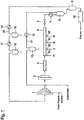
- Figure 1 shows schematically a typical set-up for a suitable tubular polymerization reactor without however restricting the invention to the embodiments described therein.
- the fresh ethylene which is usually under a pressure of 1.7 MPa, is firstly compressed to a pressure of about 30 MPa by means of a primary compressor (1) and then compressed to the reaction pressure of about 300 MPa using a secondary compressor (2).
- the molecular weight regulator is added to primary compressor (1).
- the reaction mixture leaving the primary compressor (2) is fed to pre-heater (3), where the reaction mixture is preheated to the reaction start temperature of from about 120°C to 220°C, and then conveyed to the tubular reactor (4).
- the tubular reactor (4) is basically a long, thick-walled pipe with cooling jackets to remove the liberated heat of reaction from the reaction mixture by means of a coolant circuit (not shown). It is usually from about 0.5 km to 4 km, preferably from 1.5 km to 3 km and especially from 2 km to 2.5 km long.
- the inner diameter of the pipe is usually in the range of from about 30 mm to 120 mm and preferably from 60 mm to 100 mm.
- the tubular reactor (4) shown in Figure 1 has four spatially separated initiator injection points (5a) to (5d) for feeding initiators or initiator mixtures I1 to I4 to the reactor and accordingly also four reaction zones.
- suitable free-radical initiators which decompose at the temperature of the reaction mixture
- the generated heat of the reaction rises the temperature of the reaction mixture, since more heat is generated than can be removed through the walls of the tubular reactor.
- the rising temperature increases the rate of decomposition of the free-radical initiators and accelerates polymerization until all free-radical initiators are consumed. Thereafter no further heat is generated and the temperature decreases again since the temperature of the reactor walls is lower than that of the reaction mixture.
- the part of the tubular reactor downstream of an initiator injection point, in which the temperature rises, is the reaction zone, while the part thereafter, in which the temperature decreases again, is predominantly a cooling zone.
- the amount and nature of added free-radical initiators determines how much the temperature rises and accordingly allows adjusting that value.
- the temperature rise in the first reaction zone is set to be in the range of from 70°C to 170°C and 50°C to 130°C for the subsequent reaction zones depending on the product specifications and reactor configuration.
- the reaction mixture leaves the tubular reactor (4) through a high-pressure let-down valve (6) and passes a post reactor cooler (7). Thereafter, the resulting polymer is separated off from unreacted ethylene and other low molecular weight compounds (monomers, oligomers, polymers, additives, solvent, etc.) by means of a first separation vessel (8) and a second separation vessel (9), discharged and pelletized via an extruder and granulator (10).
- the ethylene and comonomers which have been separated off in the first separation vessel (8) are fed back to the inlet end of the tube reactor (4) in the high-pressure circuit (11) at 30 MPa. They are first freed from other constituents in at least one purification stage and then added to the monomer stream between primary compressor (1) and secondary compressor (2).
- Figure 1 shows one purification stage consisting of a heat exchanger (12) and a separator (13). It is however also possible to use a plurality of purification stages.
- the high-pressure circuit (11) usually separates waxes.
- Figure 1 shows two purification stages consisting of heat exchangers (15) and (17) and separators (16) and (18). It is however also possible to use only one purification stages or preferably more than two purification stages.
- the low-pressure circuit (14) usually separates oil and waxes.
- the composition to separate in the separation vessel is a reaction mixture obtained by polymerizing ethylenically unsaturated monomers in the presence of free-radical polymerization initiators at temperatures from 100°C to 350°C and pressures in the range of from 110 MPa to 500 MPa.
- the steps of entering the reaction mixture into the separation vessel; separating the reaction mixture into in a gaseous fraction and a liquid fraction; and withdrawing the gaseous fraction from the top of the separation vessel and withdrawing the liquid fraction from the bottom of the separation vessel are performed.
- the separation is preferably carried out at a pressure of from 10 MPa to 50 MPa, more preferably from 20 MPa to 30 MPa, and preferably at a temperature of from 120°C to 300°C and more preferably from 220°C to 290°C for ethylene homopolymers and from 130°C to 260°C for ethylene copolymer.
- the polymeric components within the separating vessel are in liquid state.
- the pressure of the reaction mixture obtained in the high-pressure polymerization is usually reduced by passing the mixture through the high-pressure let-down valve arranged downstream of the polymerization reactor.
- the reaction mixture then usually passes an aftercooler or product cooler, which is supplied with hot water as cooling medium, and fed to the separation vessel for being separated in a liquid fraction and a gaseous fraction.
- an aftercooler or product cooler which is supplied with hot water as cooling medium, and fed to the separation vessel for being separated in a liquid fraction and a gaseous fraction.
- cold ethylene is added to the reaction mixture prior to entering the first separating vessel. It is also possible to separately feed cold ethylene to the separating vessel.
- the reaction mixture is fed into the separation vessel as obtained by the high-pressure polymerization, i.e. without having added to the reaction mixture any further components such as cold ethylene.
- the gaseous fraction of the reaction mixture withdrawn from the top of the separating vessel is usually fed to the high pressure recycle and, after purification and cooling, returned to the suction side of the secondary compressor.
- the gas exiting the separation vessel is preferably first fed to an heat exchanger in which the gas is cooled by hot water and thereafter to a further separator, in which most of the carried over polymeric and oligomeric materials and impurities are separated from the gas. By passing additional cooling and separating steps, the gas is usually further purified.
- the liquid fraction of the reaction mixture withdrawn from the bottom of the separating vessel is customarily transferred to a second separation vessel, where still dissolved low molecular compounds, mainly ethylene, is further separated off at reduced pressure.
- the cylindrical part of the separation vessel is efficiently heated by means of coils or a jacket or heating panels, through which high or medium pressure saturated steam or pressurized water at a temperature of from 120 to 300°C is passed, and the cone is more intensively heated also by means of coils or a jacket or heating panels, through which high or medium pressure saturated steam or pressurized water at a temperature of from 120 to 300°C is passed.
- the filling level of the liquid fraction in the separation vessel is measured by radiometric level measurement and is controlled by a product discharge valve which operates based on data coming from the level measurement.
- the separation vessel according to the present invention have the advantage that they allow a dead-space-free installation of the required busting discs by a relatively simple design and they can be constructed economically. It is not required to split the gas leaving the separation vessel and pass it through more than one exit line. Furthermore, a safe installation of the bursting discs is possible without employing separate massive steel blocks.
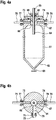
- Figure 2a shows schematically a vertical cross-section of a separation vessel according to the prior art.
- Figure 2b depicts a schematic horizontal cross-section of this separation vessel according to the prior art.
- Separation vessel (21) has a cylindrical shape and is vertically arranged. The lower end of the separation vessel is formed as cone (22).
- the composition to separate enters the separation vessel (21) from the top through a piping (23) which transforms in an inlet pipe (24).
- Separation vessel (21) is partly filled with a liquid fraction, for example with molten polymer containing dissolved gaseous components.
- the liquid fraction exits the separation vessel at the bottom through piping (25).
- the separation vessel has a manhole (26), which is surrounded by a thickened part of the separation vessel wall (27).
- the manhole (26) of the separation vessel is closed by a removable cover (28), to which the inlet pipe (24) is removably connected via flange (29).
- Cover (28) in turn is flanged to the thickened part of the separation vessel wall (27).
- the thickened part of the separation vessel wall (27) has two borings (30) and (31) to which, via flanges (32) and (33), two pipes (34) and (35) are connected through which the gaseous fraction leaves the separation vessel.
- bursting discs For installing bursting discs, two massive steel blocks (36) and (37) are inserted into pipes (34) and (35) via flanges (38) and (39) and flanges (40) and (41). Steel blocks (36) and (37) have respectively borings (42) and (43), into which bursting disc holders with integrated bursting discs are installed. To release the content of the separation vessel after a rupture of the busting disc to a safe location, vent lines (44) and (45) are connected to the steel blocks (36) and (37) via flanges (46) and (47).
- the bursting discs are located at the inner end of the bursting disc holders and accordingly installed dead-space-free in the outlet piping for transferring the gaseous fraction from the separation vessel (21) to the high-pressure gas recycle line (not shown in Figures 2a and 2b ).
- Figure 3 shows schematically more in detail a bursting disc holder with integrated bursting disc as used as well according to the prior art as in separation vessels according to the present invention.
- the bursting disc holder is basically an extended body (51) which has an opening (52) at one end and which thickens at this opening end.
- the busting disc (53) is attached to the other end of the body and fixed by an assembly nut (54).
- a vent line (not shown) is usually connected to the busting disc opening (52).
- Figure 4a shows schematically a vertical cross-section of a separation vessel according to the present invention.
- Figure 4b depicts a schematic horizontal cross-section of this separation vessel according to the present invention.
- Separation vessel (61) has a cylindrical shape and is vertically arranged. The lower end of the separation vessel is formed as cone (62).
- the composition to separate enters the separation vessel (61) from the top through a piping (63) which transforms in an inlet pipe (64).
- Separation vessel (61) is partly filled with a liquid fraction, for example with molten polymer containing dissolved gaseous components.
- the liquid fraction exits the separation vessel at the bottom through piping (65).
- the separation vessel has a manhole (66), which is surrounded by a thickened part of the separation vessel wall (67).
- the manhole (66) of the separation vessel is closed by a removable cover (68), to which the inlet pipe (64) is removably connected via flange (69).
- Cover (68) in turn is flanged to the thickened part of the separation vessel wall (67).
- the thickened part of the separation vessel wall (67) has one boring (70) to which, via a flanges (71), a pipe (72) is connected through which the gaseous fraction leaves the separation vessel.
- the thickened part of the separation vessel wall (67) has two additional borings (73) and (74) into which bursting disc holders with integrated bursting discs are installed.
- vent lines (75) and (76) are connected to the thickened part of the separation vessel wall (67) via flanges (77) and (78).
- the bursting discs are located at the inner end of the bursting disc holders and accordingly installed dead-space-free in the manhole of the separation vessel, through which the gaseous fraction firstly streams before leaving the separation vessel (61) through boring (70) and outlet line (72).
- FIG. 2a and 2b A comparison of Figures 2a and 2b with Figures 4a and 4b shows that designing separation vessels according to the present invention results in a much simpler design which can be constructed more economically. Installation of separate massive steel blocks can be avoided. This does not only mean that it is no longer necessary to provide such massive steel blocks but which also involves that it is no longer necessary to install structures, which allow a safe fixation of the steel blocks for catching and withstanding the forces which arise from the flow dynamics when a bursting disc ruptures.
- the present invention also refers to a process for separating, at a pressure of from 10 MPa to 50 MPa, and preferably at a temperature of from 120°C to 300°C, a composition comprising liquid components and gaseous components into a liquid fraction and a gaseous fraction, wherein the separation is carried out in such a separation vessel.
- the composition is a reaction mixture obtained by polymerizing ethylenically unsaturated monomers in the presence of free-radical polymerization initiators at temperatures from 100°C to 350°C and pressures in the range of from 110 MPa to 500 MPa.
- the separation vessel of the present invention can very advantageously be utilized in a process for preparing ethylene homopolymers or copolymers at high pressures. Accordingly the present invention also refers to a process for preparing ethylene homopolymers or copolymers from ethylenically unsaturated monomers in the presence of free-radical polymerization initiators at temperatures from 100°C to 350°C and pressures in the range of from 110 MPa to 500 MPa in a polymerization reactor, wherein the separation of the reaction mixture obtained by the polymerization is carried out in such a separation vessel.
- the separation is preferably the first separation of the reaction mixture obtained by the polymerization and the separation is carried out at a pressure of from 10 MPa to 50 MPa.
- the polymerization is preferably carried out in one or more tubular reactors or autoclave reactors or combinations of such reactors.
Description
- The present invention relates to a vessel for separating, at a pressure of from 10 MPa to 50 MPa, a composition comprising liquid components and gaseous components into a liquid fraction and a gaseous fraction, it relates to processes for separating, at a pressure of from 10 MPa to 50 MPa, a composition comprising liquid components and gaseous components into a liquid fraction and a gaseous fraction, and it relates to processes for preparing ethylene homopolymers or copolymers from ethylenically unsaturated monomers in the presence of free-radical polymerization initiators, wherein the separation of the reaction mixture obtained by the polymerization is carried out in such a separation vessel.
- Polyethylene is the most widely used commercial polymer. It can be prepared by a couple of different processes. Polymerization in the presence of free-radical initiators at elevated pressures was the method first discovered to obtain polyethylene and continues to be a valued process with high commercial relevance for the preparation of low density polyethylene (LDPE).
- A normal set-up of a plant for preparing low density polyethylene comprises, beside a polymerization reactor which can be an autoclave or a tubular reactor or a combination of such reactors, further equipment. For pressurizing the reaction components, usually a set of two compressors, a primary and a secondary compressor, is used. At the end of the polymerization sequence, a high-pressure polymerization unit normally further includes apparatuses like extruders and granulators for pelletizing the obtained polymer. Furthermore, such a polymerization unit generally also comprises means for feeding monomers and comonomers, free-radical initiators, modifiers or other substances at one or more positions to the polymerization reaction.
- A characteristic of the radically initiated polymerization of ethylenically unsaturated monomers under high pressure is that the conversion of the monomers is by far not complete. Per pass of the reactor, only about 10% to 50% of the dosed monomers are converted in case of a polymerization in a tubular reactor and from 8% to 30 % of the dosed monomers are converted in case of a polymerization in an autoclave reactor. Accordingly, it is common practice to separate the discharged reaction mixture into polymeric and gaseous components and recycle the monomers. To avoid unnecessary decompression and compression steps, the separation into polymeric and gaseous components is usually carried out in two stages. The monomer-polymer mixture leaving the reactor is transferred to a first separating vessel, frequently called high-pressure product separator, in which the separation in polymeric and gaseous components is carried out at a pressure that allows recycling the ethylene and comonomers separated from the monomer-polymer mixture to the reaction mixture at a position between the primary compressor and the secondary compressor. At the conditions of operating the first separation vessel, the polymeric components within the separating vessel are in liquid state. The level of the liquid phase in the first separating vessel is generally measured by radiometric level measurement and is controlled automatically by a product discharge valve. The liquid phase obtained in the first separating vessel is transferred to a second separation vessel, frequently called low-pressure product separator, in which a further separation in polymeric and gaseous components takes place at lower pressure. The ethylene and comonomers separated from the mixture in the second separation vessel are fed to the primary compressor where they are compressed to the pressure of the fresh ethylene feed, combined with the fresh ethylene feed and the joined streams are further pressurized to the pressure of the high-pressure gas recycle stream.
- The first separation vessel, which generally operates at a pressure in the range of from 10 MPa to 50 MPa, is usually equipped with safety devices for protecting the vessel from over-pressurization. The commonly utilized devices are bursting discs. The bursting discs are usually installed at the exit lines of the separation vessels through which the gaseous fraction exits the separation vessel for being recycled to the secondary compressor. To prevent blocking of the bursting discs by polymer entrained by the recycle gas, dead space in front of the bursting discs should be avoided. For safety reasons, the bursting discs are very often installed within a massive steel block.
- New modern world scale plants are designed with a much higher capacity of a single production line than in the past. Due to the higher throughput, is it necessary to use separating vessels of a larger dimension and accordingly the volume which has to be depressurized by failing bursting discs increases. Since the diameter of available bursting discs is limited, this requires the installation of more than one bursting disc to allow a sufficiently fast pressure release. Moreover, since the installation of a bursting disc unit requires a certain assembling volume and, to avoid dead space, the bursting discs should be installed directly at lines with permanent gas flow, it has become necessary to convey the gas exiting the separation vessel through more than one exit line to establish enough capability for installing bursting discs in the proximity of the first separation vessel.
- Accordingly it was the objective of the present invention to overcome the disadvantages of the prior art and provide a separation vessel with a dead-space-free installation of one or more busting discs, which separation vessel has a relatively simple design and can be constructed economically and which separation vessel does not require a split of the gas leaving the separation vessel to pass through more than one exit line, and an installation of bursting discs in separate massive steel blocks can be avoided.
- We have found that this objective was achieved by a vessel for separating, at a pressure of from 10 MPa to 50 MPa, a composition comprising liquid components and gaseous components into a liquid fraction and a gaseous fraction, wherein
the separation vessel has a cylindrical shape and is vertically arranged,
the separation vessel has at its top a manhole, which is surrounded by a thickened part of the separation vessel wall;
the separation vessel is equipped with means for introducing the composition into the separation vessel, with means for withdrawing a gaseous fraction from the top of the separation vessel, and with means for withdrawing a liquid fraction from the bottom of the separation vessel; and
the separation vessel bears at least one bursting disc which is held by a bursting disc holder which is installed pressure-tight within a boring in the thickened part of the separation vessel wall. - Furthermore, we have found a process for separating, at a pressure of from 10 MPa to 50 MPa, a composition comprising liquid components and gaseous components into a liquid fraction and a gaseous fraction, and a process for preparing ethylene homopolymers or copolymers from ethylenically unsaturated monomers in the presence of free-radical polymerization initiators at temperatures from 100°C to 350°C and pressures in the range of from 110 MPa to 500 MPa in a polymerization reactor wherein the separation of the reaction mixture obtained by the polymerization is carried out in such a separation vessel.
-
-
Figure 1 shows schematically a typical set-up for a suitable tubular polymerization reactor. -
Figure 2a shows schematically a vertical cross-section of a separation vessel according to the prior art.Figure 2b depicts a schematic horizontal cross-section of this separation vessel according to the prior art. -
Figure 3 shows schematically a bursting disc holder with integrated bursting disc as used as well according to the prior art as in separation vessels according to the present invention. -
Figure 4a shows schematically a vertical cross-section of a separation vessel according to the present invention.Figure 4b depicts a schematic horizontal cross-section of this separation vessel according to the present invention. - The present invention refers to a vessel for separating, at a pressure of from 10 MPa to 50 MPa and preferably of from 20 MPa to 30 MPa, a composition comprising liquid components and gaseous components into a liquid fraction and a gaseous fraction. The separation vessel is equipped with means for introducing the composition into the separation vessel, with means for withdrawing a gaseous fraction from the top of the separation vessel, and with means for withdrawing a liquid fraction from the bottom of the separation vessel. The means for withdrawing a gaseous fraction from the top of the separation vessel is preferably a gas outlet at the top of the separation vessel. The means for withdrawing the liquid fraction from the bottom of the separation vessel is preferably an outlet for a liquid phase at the bottom of the separation vessel. Preferably the lower end of the separation vessel is formed as cone.
- The separation vessel according to the present invention has a cylindrical shape and is vertically arranged. Preferably the separation vessel has a ratio of length to diameter L/D of from 4 to 10, more preferably from 5 to 8. The values for the vessel length and the vessel diameter refer to the inner dimensions. Preferably the length of the separation vessel is in the range of from 3 meter to 20 meter and more preferably in the range of from 5 meter to 15 meter. The vessel diameter is preferably in the range of from 0.5 meter to 2.5 meter and more preferably in the range of from 1 meter to 2 meter. If the lower end of the separation vessel is formed as cone, the height of the cone is included in the vessel length.
- The separation vessel has at its top a manhole, which is surrounded by a thickened part of the separation vessel wall. Preferably the diameter of the manhole is at least 0.4 meter and more preferably the diameter of the manhole is in the range of from 0.5 meter to 0.8 meter. The thickened part of the separation vessel wall at the top of the separation vessel comes from a design that the diameter of the manhole is smaller than the inner diameter of the separation vessel in its cylindrical part while the outer diameter of the separation vessel in the region of the manhole is not reduced by the same ratio. Preferably the separation vessel is constructed in a way that the outer diameter of the separation vessel remains constant at the top of the vessel, that means that the outer diameter of the separation vessel at its top is identical to the outer diameter of the separation vessel in its cylindrical part and the separation vessel accordingly does not taper to its top, while the inner diameter of the separation vessel in its cylindrical part is larger than the diameter of the manhole. Typically the manhole is closed by a cover, which is usually connected pressure tight to the separation vessel body, preferably by screws. Preferably the screws for connecting the cover with the separation vessel body are mounted to the top of the thickened part of the separation vessel wall.
- Typical volumes for separation vessels according to the present invention are in the range from 4 m3 to 20 m3. Such separation vessels are for example used as high-pressure product separators in high-pressure polymerization plants with an annual capacity of 80,000 to 500,000 tons of LDPE.
- The means for introducing the composition into the separation vessel can be an inlet in the wall of the separation vessel. Preferably the means for introducing the composition into the separation vessel is an inlet pipe, commonly also called dip tube, which extends vertically from the top into the separation vessel. Such an inlet pipe is preferably centrally arranged in the separation vessel and integrated into the cover of the manhole. Preferably the inlet pipe is connected to the cover via a removable flange.
- For preferred inlet pipes, the ratio of the inner diameter of the inlet pipe at its lower end, i.e. at the outlet of the pipe, and the inner diameter of the separating vessel in its cylindrical part is in the range of from 0.2 to 0.4 and more preferably in the range of from 0.22 to 0.35. The realization of the preferred ratio of the inner diameter of the inlet pipe at its lower end to the inner diameter of the separating vessel in its cylindrical part is preferably achieved by utilizing, as inlet pipe, a tube which widens in its lower part. The inlet pipe can preferably be remounted, i.e. pulled out of the separation vessel, by disconnecting a special manhole flange on top of the vessel.
- According to a preferred embodiment of the present invention, the inlet pipe extends for a distance into the separation vessel which is from 25% to 50% of the length of the separation vessel and more preferably from 30% to 40% of the length of the separation vessel.
- The separation vessel according to the present invention is characterized in that the separation vessel bears at least one bursting disc which is held by a bursting disc holder which is installed pressure-tight within a boring in the thickened part of the separation vessel wall. Bursting discs, frequently also designated as burst discs or rupture discs, are non-reclosing pressure relief devices which protect pressure vessels or pressure systems as final protection elements from over-pressurization. Bursting discs provide instant response to a pressure increase, but once the disc has ruptured it will not reseal. The busting disc as such, which is intended to fail if an over- pressurization occurs, has to be integrated in a way into the vessel or system to be protected that a not too complicated possibility for replacing failed busting discs exists. Therefore, according to the present invention, the bursting disc is held by a holder to which the bursting disc is fixed, preferably by an assembly nut or screw, in this way forming a bursting disc assembly. The bursting disc holder is connected pressure-tight to the separation vessel body. Preferably the bursting disc holder is fixed to the separation vessel wall by flange connection from the outside.
- In case the bursting disc fails, it should be ensured that the content of the separation vessel can expands through the opening, which was generated by the failing bursting disc, in an appropriate manner. Accordingly, the bursting disc holder is preferably connected to a vent line which allows conveying, in such an emergency situation, the content of the separation vessel to a safe location such as a flare or to atmosphere, for example via a blowdown vessel. Since parts of the failing bursting disc will be shot out through the bursting disc holder, it is further preferred that devices for adsorbing the kinetic energy, so-called catchers, are installed at suitable positions in the vent lines in a way that the parts of the failing bursting discs neither plug nor leave the vent lines. Such devices for adsorbing the kinetic energy are for example piping ends which are filed with lead.
- According to the present invention, the bursting disc holder is installed in a boring in the thickened part of the separation vessel wall. This region of the separation vessel has sufficient stability that one or more holes can be drilled without compromising the pressure resistance of the separation vessel. Preferably the thickened part at the top of the separation vessel wall has at least two borings, one boring which acts as outlet for withdrawing a gaseous fraction from the top of the separation vessel and at least one boring for installing the bursting disc holder. Since up to eight holes can easily be drilled at the same height level into the thickened part of the separation vessel wall, preferred separation vessels have one boring, which acts as outlet for withdrawing a gaseous fraction from the top of the separation vessel, and from 1 to 7 borings for installing bursting disc holders. Especially preferred separation vessel have one boring, which acts as outlet for withdrawing a gaseous fraction from the top of the separation vessel, and from 1 to 3 boring for installing bursting disc holders.
- Preferably the bursting discs are arranged dead-space-free, i.e. in a way that there exists no or essentially no space for build-up of a plugging in front of the bursting disc, at a position which is in contact with the gaseous fraction within the separation vessel. The bursting discs are consequently preferably arranged at the inner end of the boring in the thickened part of the separation vessel wall in a way that the surface of the bursting disc assembly in contact with the gaseous fraction within the separation vessel and the wall surface of the manhole are arranged in one plane. It has to be understood that because of constructional reasons the outer surface of the bursting disc is commonly not exactly at the level of the outer surface of the bursting disc assembly. Usually the bursting disc is fixed to the bursting disc holder by a clamping nut which embraces the bursting disc at its outer edge and leaves the central part uncovered. Such a gap between the bursting disc and the wall surface of the manhole, i.e. the distance between the plane of the outer surface of the bursting disc and the plane of the wall surface of the manhole, is commonly in the magnitude of several millimeters and often in the range of from 2 to 10 mm.
- The separation vessels of the present invention are preferably employed as high-pressure product separators in a high-pressure polymerization of ethylenically unsaturated monomers in the presence of free-radical polymerization initiators. The high-pressure polymerization is preferably a homopolymerization of ethylene or a copolymerization of ethylene with one or more other monomers, provided that these monomers are free-radically copolymerizable with ethylene under high pressure. Examples of suitable copolymerizable monomers are α,β-unsaturated C3-C8-carboxylic acids, in particular maleic acid, fumaric acid, itaconic acid, acrylic acid, methacrylic acid and crotonic acid, derivatives of α,β-unsaturated C3-C8-carboxylic acids, e.g. unsaturated C3-C15-carboxylic esters, in particular esters of C1-C6-alkanols, or anhydrides, in particular methyl methacrylate, ethyl methacrylate, n-butyl methacrylate or tert-butyl methacrylate, methyl acrylate, ethyl acrylate, n-butyl acrylate, 2-ethylhexyl acrylate, tert-butyl acrylate, methacrylic anhydride, maleic anhydride or itaconic anhydride, and 1-olefins such as propene, 1-butene, 1-pentene, 1-hexene, 1-octene or 1-decene. In addition, vinyl carboxylates, particularly preferably vinyl acetate, can be used as comonomers. Propene, 1-butene, 1-hexene, acrylic acid, n-butyl acrylate, tert-butyl acrylate, 2-ethylhexyl acrylate, vinyl acetate or vinyl propionate are particularly suitable as comonomer.
- In the case of copolymerization, the proportion of comonomer or comonomers in the reaction mixture is from 1 to 50% by weight, preferably from 3 to 40% by weight, based on the amount of monomers, i.e. the sum of ethylene and other monomers. Depending on the type of comonomer, it can be preferred to feed the comonomers at more than one point to the reactor set-up. Preferably the comonomers are fed to the suction side of the secondary compressor.
- For the purposes of the present invention, polymers or polymeric materials are all substances which are made up of at least two monomer units. They are preferably low density polyethylenes having an average molecular weight Mn of more than 20 000 g/mole. The term low density polyethylene is meant to include ethylene homopolymers and ethylene copolymers. The process of the present invention can also be advantageously employed in the preparation of oligomers, waxes and polymers having a molecular weight Mn of less than 20 000 g/mole.
- Possible initiators for starting the free-radical polymerization in the respective reaction zones are in general all substances that can produce radical species under the conditions in the polymerization reactor, for example, oxygen, air, azo compounds or peroxidic polymerization initiators. In a preferred embodiment of the invention the polymerizations is carried out by using oxygen, either fed in the form of pure O2 or as air. In case of initiating the polymerization with oxygen, the initiator is normally first mixed with the ethylene feed and then fed to the reactor. In such a case it is not only possible to feed a stream comprising monomer and oxygen to the beginning of the polymerization reactor but also to one or more points along the reactor creating two or more reaction zones. Initiation using organic peroxides or azo compounds also represents a preferred embodiment of the present invention. Examples of suitable organic peroxides are peroxy esters, peroxy ketals, peroxy ketones and peroxycarbonates, e.g. di(2-ethylhexyl) peroxydicarbonate, dicyclohexyl peroxydicarbonate, diacetyl peroxydicarbonate, tert-butyl peroxyisopropylcarbonate, di-sec-butyl peroxydicarbonate, di-tert-butyl peroxide, di-tert-amyl peroxide, dicumyl peroxide, 2,5-dimethyl-2,5-di-tert-butylperoxyhexane, tert-butyl cumyl peroxide, 2,5-dimethyl-2,5-di(tert-butylperoxy)hex-3-yne, 1,3-diisopropyl monohydroperoxide or tert-butyl hydroperoxide, didecanoyl peroxide, 2,5-dimethyl-2,5-di(2-ethylhexanoylperoxy)hexane, tert-amyl peroxy-2-ethylhexanoate, dibenzoyl peroxide, tert-butyl peroxy-2-ethylhexanoate, tert-butyl peroxydiethylacetate, tert-butyl peroxydiethylisobutyrate, tert-butyl peroxy-3,5,5-trimethylhexanoate, 1,1-di(tert-butylperoxy)-3,3,5-trimethylcyclohexane, 1,1-di(tert-butylperoxy)cyclohexane, tert-butyl peroxyacetate, cumyl peroxyneodecanoate, tert-amyl peroxyneodecanoate, tert-amyl peroxypivalate, tert-butyl peroxyneodecanoate, tert-butyl permaleate, tert-butyl peroxypivalate, tert-butyl peroxyisononanoate, diisopropylbenzene hydroperoxide, cumene hydroperoxide, tert-butyl peroxybenzoate, methyl isobutyl ketone hydroperoxide, 3,6,9-triethyl-3,6,9-trimethyl-triperoxocyclononane and 2,2-di(tert-butylperoxy)butane. Azoalkanes (diazenes), azodicarboxylic esters, azodicarboxylic dinitriles such as azobisisobutyronitrile and hydrocarbons which decompose into free radicals and are also referred as C-C initiators, e.g. 1,2-diphenyl-1,2-dimethylethane derivatives and 1,1,2,2-tetramethylethane derivatives, are also suitable. It is possible to use either individual initiators or preferably mixtures of various initiators. A large range of initiators, in particular peroxides, are commercially available, for example the products of Akzo Nobel offered under the trade names Trigonox® or Perkadox®.
- Suitable peroxidic polymerization initiators include, for example, 1,1-di(tert-butylperoxy)cyclohexane, 2,2-di(tert-butylperoxy)butane, tert-butyl peroxy-3,5,5-trimethylhexanoate, tert-butyl peroxybenzoate, 2,5-dimethyl-2,5-di(tert-butylperoxy)hexane, tert-butyl cumyl peroxide, di-tert-butyl peroxide and 2,5-dimethyl-2,5-di(tert-butylperoxy)hex-3-yne, and particular preference is given to using tert-butyl peroxy-3,5,5-trimethylhexanoate, di-(2-ethylhexyl)peroxydicarbonate or tert-butyl peroxy-2-ethylhexanoate.
- The initiators can be employed individually or as a mixture in concentrations of from 0.1 mol/t to 50 mol/t of polyethylene produced, in particular from 0.2 mol/t to 20 mol/t, in each reaction zone. In a preferred embodiment of the present invention the free-radical polymerization initiator, which is fed to a reaction zone, is a mixture of at least two different azo compounds or organic peroxides. If such initiator mixtures are used it is preferred that these are fed to all reaction zones. There is no limit for the number of different initiators in such a mixture, however preferably the mixtures are composed of from two to six and in particular of two, three or four different initiators. Particular preference is given to using mixtures of initiators which have different decomposition temperatures.
- It is often advantageous to use the initiators in the dissolved state. Examples of suitable solvents are ketones and aliphatic hydrocarbons, in particular octane, decane and isododecane and also other saturated C8-C25-hydrocarbons. The solutions comprise the initiators or initiator mixtures in proportions of from 2 to 65% by weight, preferably from 5 to 40% by weight and particularly preferably from 8 to 30% by weight.
- In the high-pressure polymerization, the molecular weight of the polymers to be prepared can as usual be altered by addition of modifiers which act as chain-transfers agents. Examples of suitable modifiers are hydrogen, aliphatic and olefinic hydrocarbons, e.g. propane, butane, pentane, hexane, cyclohexane, propene, 1-butene, 1-pentene or 1-hexene, ketones such as acetone, methyl ethyl ketone (2-butanone), methyl isobutyl ketone, methyl isoamyl ketone, diethyl ketone or diamyl ketone, aldehydes such as formaldehyde, acetaldehyde or propionaldehyde and saturated aliphatic alcohols such as methanol, ethanol, propanol, isopropanol or butanol. Particular preference is given to using saturated aliphatic aldehydes, in particular propionaldehyde or 1-olefins such as propene, 1-butene or 1-hexene, or aliphatic hydrocarbons such as propane.
- The high-pressure polymerization is preferably carried out at pressures of from 110 MPa to 500 MPa, with pressures of from 160 MPa to 350 MPa being preferred and pressures of from 200 MPa to 330 MPa being particularly preferred for polymerization in a tubular reactor and with pressures of from 110 MPa to 300 MPa being preferred and pressures of from 120 MPa to 280 MPa being particularly preferred for polymerization in an autoclave reactor. The polymerization temperatures are usually in the range of from 100°C to 350°C and preferably in the range of from 180°C to 340°C and more preferably from 200°C to 330°C for polymerization in a tubular reactor and preferably in the range of from 110°C to 320°C and more preferably from 120°C to 310°C for polymerization in an autoclave reactor.
- The polymerization can be carried out with all types of high-pressure reactors appropriate for high-pressure polymerization. Suitable high-pressure reactors are, for example, tubular reactors or autoclave reactors or combinations of such reactors. Preferably the high-pressure reactors are tubular reactors or autoclave reactors and in particular tubular reactors.
- Common high-pressure autoclave reactors are stirred reactors and have a length-to-diameter ratio of in the range from 2 to 30, preferably from 2 to 20. Such autoclave reactors have one or more reaction zones, preferably from 1 to 6 reaction zones and more preferably from 1 to 4 reaction zones. The number of reaction zones depends from the number of agitator baffles which separate individual mixed zones within the autoclave reactor.
- Appropriate tubular reactors are basically long, thick-walled pipes, which are usually from about 0.5 km to 4 km, preferably from 1 km to 3 km and especially from 1.5 km to 2.5 km long. The inner diameter of the pipes is usually in the range of from about 30 mm to 120 mm and preferably from 60 mm to 100 mm. Such tubular reactors have preferably a length-to-diameter ratio of greater than 1000, preferably from 10000 to 40000 and especially from 25000 to 35000.
- Preferred tubular reactors have at least two reaction zones, preferably from 2 to 6 reaction zones and more preferably from 2 to 5 reaction zones. The number of reaction zones is given by the number of feeding points for the initiator. Such a feeding point can, for example, be an injection point for a solution of azo compounds or organic peroxides. Fresh initiator is added to the reactor, where it decomposes into free radicals and initiates further polymerization. The generated heat of the reaction rises the temperature of the reaction mixture, since more heat is generated than can be removed through the walls of the tubular reactor. The rising temperature increases the rate of decomposition of the free-radical initiators and accelerates polymerization until essentially all free-radical initiator is consumed. Thereafter no further heat is generated and the temperature decreases again since the temperature of the reactor walls is lower than that of the reaction mixture. Accordingly, the part of the tubular reactor downstream of an initiator feeding point in which the temperature rises is the reaction zone, while the part thereafter, in which the temperature decreases again, is predominantly a cooling zone. The amount and nature of added free-radical initiators determines how much the temperature rises and accordingly allows adjusting that value. Normally, the temperature rise is set to be in the range of from 70°C to 170°C in the first reaction zone and 50°C to 130°C for the subsequent reaction zones depending on the product specifications and the reactor configuration.
- The compression of the reaction gas composition to the polymerization pressure is preferably carried out by at least two sequentially operating compressors of which a primary compressor first compresses the reaction gas composition to a pressure of from 10 MPa to 50 MPa and a secondary compressor, which is sometimes designated as hyper compressor, then further compresses the reaction gas composition to the polymerization pressure of from 110 MPa to 500 MPa. Preferably the primary compressor and the secondary compressor are multistage compressors. It is further possible to separate one or more stages of one or both of these compressors and divide them into separated compressors. However, usually a series of one primary compressor and one secondary compressor is used for compressing the reaction gas composition to the polymerization pressure. In such cases, sometimes the whole primary compressor is designated as primary compressor. However, it is also common to designate the one or more first stages of the primary compressor, which compress the recycle gas from the low-pressure product separator to the pressure of the fresh ethylene feed, as booster compressor and then only the one or more subsequent stages as primary compressor although they are all part of one apparatus.
- Commonly the polymerization apparatus comprises, beside the polymerization reactor, a high-pressure gas recycle line and a low-pressure gas recycle line for recycling not reacted monomers to the polymerization process. The reaction mixture obtained in the polymerization reactor is transferred to a first separation vessel, frequently called high-pressure product separator, which is according to the present invention a separation vessel, which bears at least one bursting disc which is held by a bursting disc holder which is installed pressure-tight within a boring in the thickened part of the separation vessel wall, and therein separated into a gaseous fraction and a liquid fraction at a pressure of from 10 MPa to 50 MPa. The gaseous fraction withdrawn from this separation vessel is fed via the high-pressure gas recycle line to the suction side of the secondary compressor. In the high-pressure gas recycle line, the gas is usually purified by several purifications steps from undesired components such as entrained polymer or oligomers. The liquid fraction withdrawn from the first separation vessel, which usually still comprises dissolved monomers such as ethylene and comonomers in an amount of 20 to 40% of weight, is transferred to a second separation vessel, frequently called low-pressure product separator, and further separated, at reduced pressure, usually at an absolute pressure in the range of from 0.1 to 0.5 MPa, in polymeric and gaseous components. The gaseous fraction withdrawn from the second separation vessel is fed via the low-pressure gas recycle line to the primary compressor, preferably to the foremost of the stages. Also the low-pressure gas recycle line usually comprises several purifications steps for purifying the gas from undesired components.
- Preferably, the recycled gas coming from the low-pressure gas recycle line is compressed by first stages of the primary compressor to the pressure of the fresh feed of ethylenically unsaturated monomers, preferably ethylene, thereafter combined with the fresh gas feed and the combined gases are further compressed in the primary compressor to the pressure of from 10 MPa to 50 MPa. Preferably the primary compressor comprises five or six compression stages, two or three before adding the fresh gas and two or three after adding the fresh gas. The secondary compressor has preferably two stages; a first stage, which compresses the gas from about 30 MPa to about 120 MPa, and a second stage, which further compresses the gas from about 120 MPa to the final polymerization pressure.
- Different configurations for suitable polymerization apparatuses such as for example autoclave reactors are of course also possible.
-
Figure 1 shows schematically a typical set-up for a suitable tubular polymerization reactor without however restricting the invention to the embodiments described therein. - The fresh ethylene, which is usually under a pressure of 1.7 MPa, is firstly compressed to a pressure of about 30 MPa by means of a primary compressor (1) and then compressed to the reaction pressure of about 300 MPa using a secondary compressor (2). The molecular weight regulator is added to primary compressor (1). The reaction mixture leaving the primary compressor (2) is fed to pre-heater (3), where the reaction mixture is preheated to the reaction start temperature of from about 120°C to 220°C, and then conveyed to the tubular reactor (4).
- The tubular reactor (4) is basically a long, thick-walled pipe with cooling jackets to remove the liberated heat of reaction from the reaction mixture by means of a coolant circuit (not shown). It is usually from about 0.5 km to 4 km, preferably from 1.5 km to 3 km and especially from 2 km to 2.5 km long. The inner diameter of the pipe is usually in the range of from about 30 mm to 120 mm and preferably from 60 mm to 100 mm.
- The tubular reactor (4) shown in
Figure 1 has four spatially separated initiator injection points (5a) to (5d) for feeding initiators or initiator mixtures I1 to I4 to the reactor and accordingly also four reaction zones. By feeding suitable free-radical initiators, which decompose at the temperature of the reaction mixture, to the tubular reactor the polymerization reaction starts. The generated heat of the reaction rises the temperature of the reaction mixture, since more heat is generated than can be removed through the walls of the tubular reactor. The rising temperature increases the rate of decomposition of the free-radical initiators and accelerates polymerization until all free-radical initiators are consumed. Thereafter no further heat is generated and the temperature decreases again since the temperature of the reactor walls is lower than that of the reaction mixture. Accordingly, the part of the tubular reactor downstream of an initiator injection point, in which the temperature rises, is the reaction zone, while the part thereafter, in which the temperature decreases again, is predominantly a cooling zone. - The amount and nature of added free-radical initiators determines how much the temperature rises and accordingly allows adjusting that value. Normally, the temperature rise in the first reaction zone is set to be in the range of from 70°C to 170°C and 50°C to 130°C for the subsequent reaction zones depending on the product specifications and reactor configuration. The reaction mixture leaves the tubular reactor (4) through a high-pressure let-down valve (6) and passes a post reactor cooler (7). Thereafter, the resulting polymer is separated off from unreacted ethylene and other low molecular weight compounds (monomers, oligomers, polymers, additives, solvent, etc.) by means of a first separation vessel (8) and a second separation vessel (9), discharged and pelletized via an extruder and granulator (10).
- The ethylene and comonomers which have been separated off in the first separation vessel (8) are fed back to the inlet end of the tube reactor (4) in the high-pressure circuit (11) at 30 MPa. They are first freed from other constituents in at least one purification stage and then added to the monomer stream between primary compressor (1) and secondary compressor (2).
Figure 1 shows one purification stage consisting of a heat exchanger (12) and a separator (13). It is however also possible to use a plurality of purification stages. The high-pressure circuit (11) usually separates waxes. - The ethylene which has been separated off in the second separation vessel (9), which further comprises, inter alia, the major part of the low molecular weight products of the polymerization (oligomers) and the solvent, is worked up in the low-pressure circuit (14) at an absolute pressure of from about 0.1 to 0.5 MPa in a plurality of separators with a heat exchanger being located between each of the separators.
Figure 1 shows two purification stages consisting of heat exchangers (15) and (17) and separators (16) and (18). It is however also possible to use only one purification stages or preferably more than two purification stages. The low-pressure circuit (14) usually separates oil and waxes. - Different configurations for suitable tubular polymerization reactor are of course also possible. It can be advantageous to add the monomers not only at the inlet of the reactor tube but to feed them, preferably cooled, at a plurality of different points to the reactor. This is particularly preferably done at the beginning of further reaction zones and especially if oxygen or air is used as initiators, which is usually added to the monomer feed in the primary compressor.
- If the separation vessels of the present invention are employed as high-pressure product separators in a high-pressure polymerization of ethylenically unsaturated monomers, the composition to separate in the separation vessel is a reaction mixture obtained by polymerizing ethylenically unsaturated monomers in the presence of free-radical polymerization initiators at temperatures from 100°C to 350°C and pressures in the range of from 110 MPa to 500 MPa.
- For separating polymeric and gaseous components of this reaction mixture, the steps of entering the reaction mixture into the separation vessel; separating the reaction mixture into in a gaseous fraction and a liquid fraction; and withdrawing the gaseous fraction from the top of the separation vessel and withdrawing the liquid fraction from the bottom of the separation vessel are performed. The separation is preferably carried out at a pressure of from 10 MPa to 50 MPa, more preferably from 20 MPa to 30 MPa, and preferably at a temperature of from 120°C to 300°C and more preferably from 220°C to 290°C for ethylene homopolymers and from 130°C to 260°C for ethylene copolymer. At the conditions of operating the separation vessel, the polymeric components within the separating vessel are in liquid state.
- The pressure of the reaction mixture obtained in the high-pressure polymerization is usually reduced by passing the mixture through the high-pressure let-down valve arranged downstream of the polymerization reactor. The reaction mixture then usually passes an aftercooler or product cooler, which is supplied with hot water as cooling medium, and fed to the separation vessel for being separated in a liquid fraction and a gaseous fraction. For cooling the reaction mixture and/or removing impurities from the polymer products it is possible that cold ethylene is added to the reaction mixture prior to entering the first separating vessel. It is also possible to separately feed cold ethylene to the separating vessel. Preferably the reaction mixture is fed into the separation vessel as obtained by the high-pressure polymerization, i.e. without having added to the reaction mixture any further components such as cold ethylene.
- The gaseous fraction of the reaction mixture withdrawn from the top of the separating vessel is usually fed to the high pressure recycle and, after purification and cooling, returned to the suction side of the secondary compressor. For purifying, the gas exiting the separation vessel is preferably first fed to an heat exchanger in which the gas is cooled by hot water and thereafter to a further separator, in which most of the carried over polymeric and oligomeric materials and impurities are separated from the gas. By passing additional cooling and separating steps, the gas is usually further purified.
- The liquid fraction of the reaction mixture withdrawn from the bottom of the separating vessel is customarily transferred to a second separation vessel, where still dissolved low molecular compounds, mainly ethylene, is further separated off at reduced pressure.
- Preferably the cylindrical part of the separation vessel is efficiently heated by means of coils or a jacket or heating panels, through which high or medium pressure saturated steam or pressurized water at a temperature of from 120 to 300°C is passed, and the cone is more intensively heated also by means of coils or a jacket or heating panels, through which high or medium pressure saturated steam or pressurized water at a temperature of from 120 to 300°C is passed.
- In a preferred embodiment of the present invention the filling level of the liquid fraction in the separation vessel is measured by radiometric level measurement and is controlled by a product discharge valve which operates based on data coming from the level measurement.
- The separation vessel according to the present invention have the advantage that they allow a dead-space-free installation of the required busting discs by a relatively simple design and they can be constructed economically. It is not required to split the gas leaving the separation vessel and pass it through more than one exit line. Furthermore, a safe installation of the bursting discs is possible without employing separate massive steel blocks.
- For illustrating the advantages of the present invention,
Figure 2a shows schematically a vertical cross-section of a separation vessel according to the prior art.Figure 2b depicts a schematic horizontal cross-section of this separation vessel according to the prior art. - Separation vessel (21) has a cylindrical shape and is vertically arranged. The lower end of the separation vessel is formed as cone (22).
- The composition to separate enters the separation vessel (21) from the top through a piping (23) which transforms in an inlet pipe (24). Separation vessel (21) is partly filled with a liquid fraction, for example with molten polymer containing dissolved gaseous components. The liquid fraction exits the separation vessel at the bottom through piping (25).
- At the top, the separation vessel has a manhole (26), which is surrounded by a thickened part of the separation vessel wall (27). The manhole (26) of the separation vessel is closed by a removable cover (28), to which the inlet pipe (24) is removably connected via flange (29). Cover (28) in turn is flanged to the thickened part of the separation vessel wall (27).
- The thickened part of the separation vessel wall (27) has two borings (30) and (31) to which, via flanges (32) and (33), two pipes (34) and (35) are connected through which the gaseous fraction leaves the separation vessel.
- For installing bursting discs, two massive steel blocks (36) and (37) are inserted into pipes (34) and (35) via flanges (38) and (39) and flanges (40) and (41). Steel blocks (36) and (37) have respectively borings (42) and (43), into which bursting disc holders with integrated bursting discs are installed. To release the content of the separation vessel after a rupture of the busting disc to a safe location, vent lines (44) and (45) are connected to the steel blocks (36) and (37) via flanges (46) and (47). The bursting discs are located at the inner end of the bursting disc holders and accordingly installed dead-space-free in the outlet piping for transferring the gaseous fraction from the separation vessel (21) to the high-pressure gas recycle line (not shown in
Figures 2a and2b ). -
Figure 3 shows schematically more in detail a bursting disc holder with integrated bursting disc as used as well according to the prior art as in separation vessels according to the present invention. - The bursting disc holder is basically an extended body (51) which has an opening (52) at one end and which thickens at this opening end. The busting disc (53) is attached to the other end of the body and fixed by an assembly nut (54). To release the content of the separation vessel after a rupture of the busting disc (53) to a safe location, a vent line (not shown) is usually connected to the busting disc opening (52).
-
Figure 4a shows schematically a vertical cross-section of a separation vessel according to the present invention.Figure 4b depicts a schematic horizontal cross-section of this separation vessel according to the present invention. - Separation vessel (61) has a cylindrical shape and is vertically arranged. The lower end of the separation vessel is formed as cone (62).
- The composition to separate enters the separation vessel (61) from the top through a piping (63) which transforms in an inlet pipe (64). Separation vessel (61) is partly filled with a liquid fraction, for example with molten polymer containing dissolved gaseous components. The liquid fraction exits the separation vessel at the bottom through piping (65).
- At the top, the separation vessel has a manhole (66), which is surrounded by a thickened part of the separation vessel wall (67). The manhole (66) of the separation vessel is closed by a removable cover (68), to which the inlet pipe (64) is removably connected via flange (69). Cover (68) in turn is flanged to the thickened part of the separation vessel wall (67).
- The thickened part of the separation vessel wall (67) has one boring (70) to which, via a flanges (71), a pipe (72) is connected through which the gaseous fraction leaves the separation vessel.
- The thickened part of the separation vessel wall (67) has two additional borings (73) and (74) into which bursting disc holders with integrated bursting discs are installed. To release the content of the separation vessel after a rupture of the busting disc to a safe location, vent lines (75) and (76) are connected to the thickened part of the separation vessel wall (67) via flanges (77) and (78). The bursting discs are located at the inner end of the bursting disc holders and accordingly installed dead-space-free in the manhole of the separation vessel, through which the gaseous fraction firstly streams before leaving the separation vessel (61) through boring (70) and outlet line (72).
- A comparison of
Figures 2a and2b withFigures 4a and 4b shows that designing separation vessels according to the present invention results in a much simpler design which can be constructed more economically. Installation of separate massive steel blocks can be avoided. This does not only mean that it is no longer necessary to provide such massive steel blocks but which also involves that it is no longer necessary to install structures, which allow a safe fixation of the steel blocks for catching and withstanding the forces which arise from the flow dynamics when a bursting disc ruptures. - The present invention also refers to a process for separating, at a pressure of from 10 MPa to 50 MPa, and preferably at a temperature of from 120°C to 300°C, a composition comprising liquid components and gaseous components into a liquid fraction and a gaseous fraction, wherein the separation is carried out in such a separation vessel. Preferably the composition is a reaction mixture obtained by polymerizing ethylenically unsaturated monomers in the presence of free-radical polymerization initiators at temperatures from 100°C to 350°C and pressures in the range of from 110 MPa to 500 MPa.
- The separation vessel of the present invention can very advantageously be utilized in a process for preparing ethylene homopolymers or copolymers at high pressures. Accordingly the present invention also refers to a process for preparing ethylene homopolymers or copolymers from ethylenically unsaturated monomers in the presence of free-radical polymerization initiators at temperatures from 100°C to 350°C and pressures in the range of from 110 MPa to 500 MPa in a polymerization reactor, wherein the separation of the reaction mixture obtained by the polymerization is carried out in such a separation vessel. The separation is preferably the first separation of the reaction mixture obtained by the polymerization and the separation is carried out at a pressure of from 10 MPa to 50 MPa.
- The polymerization is preferably carried out in one or more tubular reactors or autoclave reactors or combinations of such reactors.
Claims (13)
- A vessel for separating, at a pressure of from 10 MPa to 50 MPa, a composition comprising liquid components and gaseous components into a liquid fraction and a gaseous fraction, wherein
the separation vessel has a cylindrical shape and is vertically arranged,
the separation vessel has at its top a manhole, which is surrounded by a thickened part of the separation vessel wall;
the separation vessel is equipped with means for introducing the composition into the separation vessel, with means for withdrawing a gaseous fraction from the top of the separation vessel, and with means for withdrawing a liquid fraction from the bottom of the separation vessel; and
the separation vessel bears at least one bursting disc which is held by a bursting disc holder which is installed pressure-tight within a boring in the thickened part of the separation vessel wall. - The vessel according to claim 1, wherein the bursting disc holder is vertically installed in the thickened part of the separation vessel wall.
- The vessel according to claim 1 or 2, wherein the bursting disc holder is fixed to the separation vessel wall by flange connection from the outside.
- The vessel according to any of claims 1 to 3, wherein the bursting disc is arranged at the inner end of the boring in the thickened part of the separation vessel wall in a way that the surface of the bursting disc assembly in contact with the gaseous fraction within the separation vessel and the wall surface of the manhole are arranged in one plane.
- The vessel according to any of claims 1 to 4, wherein the separation vessel has an L/D ratio of from 4 to 10.
- The vessel according to any of claims 1 to 5, wherein the means for withdrawing a gaseous fraction from the top of the separation vessel is a boring in the thickened part of the separation vessel wall.
- The vessel according to any of claims 1 to 6, wherein the means for introducing the composition into the separation vessel is an inlet pipe, which extends vertically from the top into the separation vessel.
- A process for separating, at a pressure of from 10 MPa to 50 MPa, a composition comprising liquid components and gaseous components into a liquid fraction and a gaseous fraction, wherein the separation is carried out in a separation vessel according to any of claims 1 to 7.
- The process according to claim 8, wherein the separation is carried out at a temperature of from 120°C to 300°C.
- The process according to claim 8 or 9, wherein the composition is a reaction mixture obtained by polymerizing ethylenically unsaturated monomers in the presence of free-radical polymerization initiators at temperatures from 100°C to 350°C and pressures in the range of from 110 MPa to 500 MPa.
- A process for preparing ethylene homopolymers or copolymers from ethylenically unsaturated monomers in the presence of free-radical polymerization initiators at temperatures from 100°C to 350°C and pressures in the range of from 110 MPa to 500 MPa in a polymerization reactor, wherein the separation of the reaction mixture obtained by the polymerization is carried out in a separation vessel according to any of claims 1 to 7.
- The process according to claim 11, wherein the separation is the first separation of the reaction mixture obtained by the polymerization and the separation is carried out at a pressure of from 10 MPa to 50 MPa and a temperature of from 120°C to 300°C.
- The process according to claim 11 or 12, wherein the polymerization is carried out in one or more tubular reactors or autoclave reactors or combinations of such reactors.
Priority Applications (1)
| Application Number | Priority Date | Filing Date | Title |
|---|---|---|---|
| EP14812492.8A EP3083027B1 (en) | 2013-12-19 | 2014-12-15 | Vessel for separating components of a reaction mixture obtained by high-pressure polymerization of ethylenically unsaturated monomers with integrated bursting discs |
Applications Claiming Priority (3)
| Application Number | Priority Date | Filing Date | Title |
|---|---|---|---|
| EP13198363 | 2013-12-19 | ||
| EP14812492.8A EP3083027B1 (en) | 2013-12-19 | 2014-12-15 | Vessel for separating components of a reaction mixture obtained by high-pressure polymerization of ethylenically unsaturated monomers with integrated bursting discs |
| PCT/EP2014/077810 WO2015091384A1 (en) | 2013-12-19 | 2014-12-15 | Vessel for separating components of a reaction mixture obtained by high-pressure polymerization of ethylenically unsaturated monomers with integrated bursting discs |
Publications (2)
| Publication Number | Publication Date |
|---|---|
| EP3083027A1 EP3083027A1 (en) | 2016-10-26 |
| EP3083027B1 true EP3083027B1 (en) | 2017-07-12 |
Family
ID=49880468
Family Applications (1)
| Application Number | Title | Priority Date | Filing Date |
|---|---|---|---|
| EP14812492.8A Active EP3083027B1 (en) | 2013-12-19 | 2014-12-15 | Vessel for separating components of a reaction mixture obtained by high-pressure polymerization of ethylenically unsaturated monomers with integrated bursting discs |
Country Status (8)
| Country | Link |
|---|---|
| US (1) | US9637569B2 (en) |
| EP (1) | EP3083027B1 (en) |
| JP (1) | JP6211198B2 (en) |
| KR (1) | KR101827192B1 (en) |
| CN (1) | CN105792922B (en) |
| BR (1) | BR112016012152B1 (en) |
| RU (1) | RU2674968C1 (en) |
| WO (1) | WO2015091384A1 (en) |
Families Citing this family (8)
| Publication number | Priority date | Publication date | Assignee | Title |
|---|---|---|---|---|
| CN107074991B (en) * | 2014-11-13 | 2018-09-18 | 巴塞尔聚烯烃股份有限公司 | By the component separation method for the polymer-monomer mixture that the high pressure polymerisation of ethylenically unsaturated monomer obtains |
| EP3377537B2 (en) | 2015-11-18 | 2022-02-16 | Basell Polyolefine GmbH | Polymerization process with a partial shutdown phase |
| BR112018015614B1 (en) | 2016-02-15 | 2022-08-02 | Basell Polyolefine Gmbh | METHOD FOR PREPARING A DRY POWDER IN A INSTALLATION AND PROCESS FOR PREPARING A POLYOLEFIN |
| KR102267282B1 (en) * | 2017-02-28 | 2021-06-23 | 엑손모빌 케미칼 패턴츠 인코포레이티드 | Method for alleviating an overpressure condition within a vessel, pressure relief assembly, and associated separator vessel |
| DE202019100988U1 (en) * | 2019-02-21 | 2020-05-25 | Mls Mikrowellen-Labor-Systeme Gmbh | Pressure vessel system |
| EP3831472A1 (en) * | 2019-12-03 | 2021-06-09 | Basell Polyolefine GmbH | High-pressure polymerization system and high-pressure polymerization process for the polymerization of ethylenically unsaturated monomers |
| KR20230164286A (en) * | 2022-05-25 | 2023-12-04 | 성균관대학교산학협력단 | Rupturing device |
| CN116585831A (en) * | 2023-05-22 | 2023-08-15 | 上海智英化工技术有限公司 | High pressure separator and method for separating high pressure polyethylene copolymer or homopolymer from unreacted monomer and light component |
Family Cites Families (15)
| Publication number | Priority date | Publication date | Assignee | Title |
|---|---|---|---|---|
| US2353254A (en) * | 1941-10-28 | 1944-07-11 | Linde Air Prod Co | Bursting disk |
| US3448750A (en) * | 1964-07-20 | 1969-06-10 | Dover Corp W C Norris Division | Method and device for releasing pressure of a pressurized system |
| JPS504394B1 (en) * | 1970-12-30 | 1975-02-18 | ||
| DE2631834C3 (en) * | 1976-07-15 | 1980-05-14 | Basf Ag, 6700 Ludwigshafen | Process for the expansion of ethylene high pressure polymerization systems |
| SU1107888A1 (en) * | 1983-04-25 | 1984-08-15 | Николаевский Ордена Трудового Красного Знамени Кораблестроительный Институт Им.Адм.С.О.Макарова | Separator |
| GB8723034D0 (en) * | 1987-10-01 | 1988-03-23 | Dowty Maritime Systems Ltd | Gas generating devices |
| RU2236889C1 (en) * | 2003-06-23 | 2004-09-27 | Государственное образовательное учреждение высшего профессионального образования "Уфимский государственный нефтяной технический университет" | Entrainment separator |
| AT413265B (en) * | 2004-05-25 | 2006-01-15 | Boehler Hochdrucktech Gmbh | Safety valve for high pressure apparatus comprises bursting disk mounted in block connected to high pressure area, disk being attached to annular mounting with shoulder which forms seal with wall of bore in which it is mounted |
| GB0609973D0 (en) * | 2006-05-19 | 2006-06-28 | Exxonmobil Chem Patents Inc | An apparatus for the production of polyethylene and ethylene copolymers |
| KR101668890B1 (en) * | 2009-01-16 | 2016-10-24 | 바젤 폴리올레핀 게엠베하 | Ethylene polymerization in a high pressure reactor with improved initiator feeding |
| CN102282180B (en) * | 2009-01-16 | 2013-11-20 | 巴塞尔聚烯烃股份有限公司 | Method for ethylene polymerization in a tubular reactor with reduced output |
| US8181663B2 (en) * | 2009-04-13 | 2012-05-22 | Fike Corporation | Pressure relief device having support member with recessed areas |
| BR112013016031B1 (en) | 2010-12-22 | 2020-04-07 | Basell Polyolefine Gmbh | process for preparing ethylene copolymer in the presence of free radical polymerization initiator by ethylene copolymerization, ethylene copolymer obtained by such a process and its use, as well as process for coating by extruding a substrate |
| JP5685076B2 (en) * | 2010-12-27 | 2015-03-18 | イーグル工業株式会社 | accumulator |
| RU2572821C2 (en) * | 2011-03-03 | 2016-01-20 | Базелль Полиолефине Гмбх | Method for obtaining ethylene homopolymers or copolymers in tubular reactor with, at least, two reaction zones with different concentration of chain transfer agent |
-
2014
- 2014-12-15 KR KR1020167017276A patent/KR101827192B1/en active IP Right Grant
- 2014-12-15 CN CN201480066411.9A patent/CN105792922B/en active Active
- 2014-12-15 EP EP14812492.8A patent/EP3083027B1/en active Active
- 2014-12-15 US US15/106,150 patent/US9637569B2/en active Active
- 2014-12-15 JP JP2016536547A patent/JP6211198B2/en active Active
- 2014-12-15 RU RU2016126001A patent/RU2674968C1/en active
- 2014-12-15 BR BR112016012152-0A patent/BR112016012152B1/en active IP Right Grant
- 2014-12-15 WO PCT/EP2014/077810 patent/WO2015091384A1/en active Application Filing
Non-Patent Citations (1)
| Title |
|---|
| None * |
Also Published As
| Publication number | Publication date |
|---|---|
| JP2017501024A (en) | 2017-01-12 |
| JP6211198B2 (en) | 2017-10-11 |
| KR101827192B1 (en) | 2018-02-07 |
| WO2015091384A1 (en) | 2015-06-25 |
| RU2016126001A (en) | 2018-01-24 |
| US20160319046A1 (en) | 2016-11-03 |
| US9637569B2 (en) | 2017-05-02 |
| RU2674968C1 (en) | 2018-12-13 |
| CN105792922A (en) | 2016-07-20 |
| CN105792922B (en) | 2017-11-28 |
| KR20160093652A (en) | 2016-08-08 |
| BR112016012152B1 (en) | 2020-10-27 |
| EP3083027A1 (en) | 2016-10-26 |
Similar Documents
| Publication | Publication Date | Title |
|---|---|---|
| EP3083027B1 (en) | Vessel for separating components of a reaction mixture obtained by high-pressure polymerization of ethylenically unsaturated monomers with integrated bursting discs | |
| EP3077423B1 (en) | Process for separating components of a reaction mixture obtained by high-pressure polymerization of ethylenically unsaturated monomers | |
| EP3186288B1 (en) | Process for separating components of a polymer-monomer mixture obtained by high-pressure polymerization of ethylenically unsaturated monomers | |
| EP3262084B1 (en) | High-pressure polymerization process of ethylenically unsaturated monomers | |
| EP2935365B1 (en) | Process for copolymerizing ethylene and esters of vinyl alcohol | |
| EP3077422B1 (en) | Process for separating components of a reaction mixture obtained by high-pressure polymerization of ethylenically unsaturated monomers with improved level control | |
| EP4069410B1 (en) | High-pressure polymerization system and high-pressure polymerization process for the polymerization of ethylenically unsaturated monomers | |
| EP3898708B1 (en) | High-pressure polymerization process of ethylenically unsaturated monomers in a polymerization reactor |
Legal Events
| Date | Code | Title | Description |
|---|---|---|---|
| PUAI | Public reference made under article 153(3) epc to a published international application that has entered the european phase |
Free format text: ORIGINAL CODE: 0009012 |
|
| 17P | Request for examination filed |
Effective date: 20160602 |
|
| AK | Designated contracting states |
Kind code of ref document: A1 Designated state(s): AL AT BE BG CH CY CZ DE DK EE ES FI FR GB GR HR HU IE IS IT LI LT LU LV MC MK MT NL NO PL PT RO RS SE SI SK SM TR |
|
| AX | Request for extension of the european patent |
Extension state: BA ME |
|
| DAX | Request for extension of the european patent (deleted) | ||
| GRAP | Despatch of communication of intention to grant a patent |
Free format text: ORIGINAL CODE: EPIDOSNIGR1 |
|
| INTG | Intention to grant announced |
Effective date: 20170502 |
|
| GRAS | Grant fee paid |
Free format text: ORIGINAL CODE: EPIDOSNIGR3 |
|
| GRAA | (expected) grant |
Free format text: ORIGINAL CODE: 0009210 |
|
| AK | Designated contracting states |
Kind code of ref document: B1 Designated state(s): AL AT BE BG CH CY CZ DE DK EE ES FI FR GB GR HR HU IE IS IT LI LT LU LV MC MK MT NL NO PL PT RO RS SE SI SK SM TR |
|
| REG | Reference to a national code |
Ref country code: GB Ref legal event code: FG4D |
|
| REG | Reference to a national code |
Ref country code: CH Ref legal event code: EP |
|
| REG | Reference to a national code |
Ref country code: AT Ref legal event code: REF Ref document number: 907822 Country of ref document: AT Kind code of ref document: T Effective date: 20170715 |
|
| REG | Reference to a national code |
Ref country code: IE Ref legal event code: FG4D |
|
| REG | Reference to a national code |
Ref country code: DE Ref legal event code: R096 Ref document number: 602014011823 Country of ref document: DE |
|
| REG | Reference to a national code |
Ref country code: NL Ref legal event code: FP |
|
| REG | Reference to a national code |
Ref country code: FR Ref legal event code: PLFP Year of fee payment: 4 |
|
| REG | Reference to a national code |
Ref country code: LT Ref legal event code: MG4D |
|
| REG | Reference to a national code |
Ref country code: AT Ref legal event code: MK05 Ref document number: 907822 Country of ref document: AT Kind code of ref document: T Effective date: 20170712 |
|
| PG25 | Lapsed in a contracting state [announced via postgrant information from national office to epo] |
Ref country code: FI Free format text: LAPSE BECAUSE OF FAILURE TO SUBMIT A TRANSLATION OF THE DESCRIPTION OR TO PAY THE FEE WITHIN THE PRESCRIBED TIME-LIMIT Effective date: 20170712 Ref country code: SE Free format text: LAPSE BECAUSE OF FAILURE TO SUBMIT A TRANSLATION OF THE DESCRIPTION OR TO PAY THE FEE WITHIN THE PRESCRIBED TIME-LIMIT Effective date: 20170712 Ref country code: HR Free format text: LAPSE BECAUSE OF FAILURE TO SUBMIT A TRANSLATION OF THE DESCRIPTION OR TO PAY THE FEE WITHIN THE PRESCRIBED TIME-LIMIT Effective date: 20170712 Ref country code: LT Free format text: LAPSE BECAUSE OF FAILURE TO SUBMIT A TRANSLATION OF THE DESCRIPTION OR TO PAY THE FEE WITHIN THE PRESCRIBED TIME-LIMIT Effective date: 20170712 Ref country code: AT Free format text: LAPSE BECAUSE OF FAILURE TO SUBMIT A TRANSLATION OF THE DESCRIPTION OR TO PAY THE FEE WITHIN THE PRESCRIBED TIME-LIMIT Effective date: 20170712 Ref country code: NO Free format text: LAPSE BECAUSE OF FAILURE TO SUBMIT A TRANSLATION OF THE DESCRIPTION OR TO PAY THE FEE WITHIN THE PRESCRIBED TIME-LIMIT Effective date: 20171012 |
|
| PG25 | Lapsed in a contracting state [announced via postgrant information from national office to epo] |
Ref country code: LV Free format text: LAPSE BECAUSE OF FAILURE TO SUBMIT A TRANSLATION OF THE DESCRIPTION OR TO PAY THE FEE WITHIN THE PRESCRIBED TIME-LIMIT Effective date: 20170712 Ref country code: BG Free format text: LAPSE BECAUSE OF FAILURE TO SUBMIT A TRANSLATION OF THE DESCRIPTION OR TO PAY THE FEE WITHIN THE PRESCRIBED TIME-LIMIT Effective date: 20171012 Ref country code: ES Free format text: LAPSE BECAUSE OF FAILURE TO SUBMIT A TRANSLATION OF THE DESCRIPTION OR TO PAY THE FEE WITHIN THE PRESCRIBED TIME-LIMIT Effective date: 20170712 Ref country code: PL Free format text: LAPSE BECAUSE OF FAILURE TO SUBMIT A TRANSLATION OF THE DESCRIPTION OR TO PAY THE FEE WITHIN THE PRESCRIBED TIME-LIMIT Effective date: 20170712 Ref country code: IS Free format text: LAPSE BECAUSE OF FAILURE TO SUBMIT A TRANSLATION OF THE DESCRIPTION OR TO PAY THE FEE WITHIN THE PRESCRIBED TIME-LIMIT Effective date: 20171112 Ref country code: RS Free format text: LAPSE BECAUSE OF FAILURE TO SUBMIT A TRANSLATION OF THE DESCRIPTION OR TO PAY THE FEE WITHIN THE PRESCRIBED TIME-LIMIT Effective date: 20170712 Ref country code: GR Free format text: LAPSE BECAUSE OF FAILURE TO SUBMIT A TRANSLATION OF THE DESCRIPTION OR TO PAY THE FEE WITHIN THE PRESCRIBED TIME-LIMIT Effective date: 20171013 |
|
| REG | Reference to a national code |
Ref country code: DE Ref legal event code: R097 Ref document number: 602014011823 Country of ref document: DE |
|
| PG25 | Lapsed in a contracting state [announced via postgrant information from national office to epo] |
Ref country code: CZ Free format text: LAPSE BECAUSE OF FAILURE TO SUBMIT A TRANSLATION OF THE DESCRIPTION OR TO PAY THE FEE WITHIN THE PRESCRIBED TIME-LIMIT Effective date: 20170712 Ref country code: DK Free format text: LAPSE BECAUSE OF FAILURE TO SUBMIT A TRANSLATION OF THE DESCRIPTION OR TO PAY THE FEE WITHIN THE PRESCRIBED TIME-LIMIT Effective date: 20170712 |
|
| PLBE | No opposition filed within time limit |
Free format text: ORIGINAL CODE: 0009261 |
|
| STAA | Information on the status of an ep patent application or granted ep patent |
Free format text: STATUS: NO OPPOSITION FILED WITHIN TIME LIMIT |
|
| PG25 | Lapsed in a contracting state [announced via postgrant information from national office to epo] |
Ref country code: SK Free format text: LAPSE BECAUSE OF FAILURE TO SUBMIT A TRANSLATION OF THE DESCRIPTION OR TO PAY THE FEE WITHIN THE PRESCRIBED TIME-LIMIT Effective date: 20170712 Ref country code: IT Free format text: LAPSE BECAUSE OF FAILURE TO SUBMIT A TRANSLATION OF THE DESCRIPTION OR TO PAY THE FEE WITHIN THE PRESCRIBED TIME-LIMIT Effective date: 20170712 Ref country code: SM Free format text: LAPSE BECAUSE OF FAILURE TO SUBMIT A TRANSLATION OF THE DESCRIPTION OR TO PAY THE FEE WITHIN THE PRESCRIBED TIME-LIMIT Effective date: 20170712 Ref country code: EE Free format text: LAPSE BECAUSE OF FAILURE TO SUBMIT A TRANSLATION OF THE DESCRIPTION OR TO PAY THE FEE WITHIN THE PRESCRIBED TIME-LIMIT Effective date: 20170712 |
|
| 26N | No opposition filed |
Effective date: 20180413 |
|
| REG | Reference to a national code |
Ref country code: CH Ref legal event code: PL |
|
| PG25 | Lapsed in a contracting state [announced via postgrant information from national office to epo] |
Ref country code: SI Free format text: LAPSE BECAUSE OF FAILURE TO SUBMIT A TRANSLATION OF THE DESCRIPTION OR TO PAY THE FEE WITHIN THE PRESCRIBED TIME-LIMIT Effective date: 20170712 |
|
| REG | Reference to a national code |
Ref country code: IE Ref legal event code: MM4A |
|
| PG25 | Lapsed in a contracting state [announced via postgrant information from national office to epo] |
Ref country code: MT Free format text: LAPSE BECAUSE OF NON-PAYMENT OF DUE FEES Effective date: 20171215 Ref country code: LU Free format text: LAPSE BECAUSE OF NON-PAYMENT OF DUE FEES Effective date: 20171215 |
|
| PG25 | Lapsed in a contracting state [announced via postgrant information from national office to epo] |
Ref country code: IE Free format text: LAPSE BECAUSE OF NON-PAYMENT OF DUE FEES Effective date: 20171215 |
|
| PG25 | Lapsed in a contracting state [announced via postgrant information from national office to epo] |
Ref country code: LI Free format text: LAPSE BECAUSE OF NON-PAYMENT OF DUE FEES Effective date: 20171231 Ref country code: CH Free format text: LAPSE BECAUSE OF NON-PAYMENT OF DUE FEES Effective date: 20171231 |
|
| PG25 | Lapsed in a contracting state [announced via postgrant information from national office to epo] |
Ref country code: MC Free format text: LAPSE BECAUSE OF FAILURE TO SUBMIT A TRANSLATION OF THE DESCRIPTION OR TO PAY THE FEE WITHIN THE PRESCRIBED TIME-LIMIT Effective date: 20170712 Ref country code: HU Free format text: LAPSE BECAUSE OF FAILURE TO SUBMIT A TRANSLATION OF THE DESCRIPTION OR TO PAY THE FEE WITHIN THE PRESCRIBED TIME-LIMIT; INVALID AB INITIO Effective date: 20141215 |
|
| GBPC | Gb: european patent ceased through non-payment of renewal fee |
Effective date: 20181215 |
|
| PG25 | Lapsed in a contracting state [announced via postgrant information from national office to epo] |
Ref country code: RO Free format text: LAPSE BECAUSE OF FAILURE TO SUBMIT A TRANSLATION OF THE DESCRIPTION OR TO PAY THE FEE WITHIN THE PRESCRIBED TIME-LIMIT Effective date: 20170712 |
|
| PG25 | Lapsed in a contracting state [announced via postgrant information from national office to epo] |
Ref country code: CY Free format text: LAPSE BECAUSE OF FAILURE TO SUBMIT A TRANSLATION OF THE DESCRIPTION OR TO PAY THE FEE WITHIN THE PRESCRIBED TIME-LIMIT Effective date: 20170712 |
|
| PG25 | Lapsed in a contracting state [announced via postgrant information from national office to epo] |
Ref country code: MK Free format text: LAPSE BECAUSE OF FAILURE TO SUBMIT A TRANSLATION OF THE DESCRIPTION OR TO PAY THE FEE WITHIN THE PRESCRIBED TIME-LIMIT Effective date: 20170712 |
|
| PG25 | Lapsed in a contracting state [announced via postgrant information from national office to epo] |
Ref country code: GB Free format text: LAPSE BECAUSE OF NON-PAYMENT OF DUE FEES Effective date: 20181215 |
|
| PG25 | Lapsed in a contracting state [announced via postgrant information from national office to epo] |
Ref country code: TR Free format text: LAPSE BECAUSE OF FAILURE TO SUBMIT A TRANSLATION OF THE DESCRIPTION OR TO PAY THE FEE WITHIN THE PRESCRIBED TIME-LIMIT Effective date: 20170712 |
|
| PG25 | Lapsed in a contracting state [announced via postgrant information from national office to epo] |
Ref country code: PT Free format text: LAPSE BECAUSE OF FAILURE TO SUBMIT A TRANSLATION OF THE DESCRIPTION OR TO PAY THE FEE WITHIN THE PRESCRIBED TIME-LIMIT Effective date: 20170712 |
|
| PG25 | Lapsed in a contracting state [announced via postgrant information from national office to epo] |
Ref country code: AL Free format text: LAPSE BECAUSE OF FAILURE TO SUBMIT A TRANSLATION OF THE DESCRIPTION OR TO PAY THE FEE WITHIN THE PRESCRIBED TIME-LIMIT Effective date: 20170712 |
|
| PGFP | Annual fee paid to national office [announced via postgrant information from national office to epo] |
Ref country code: BE Payment date: 20221110 Year of fee payment: 9 |
|
| P01 | Opt-out of the competence of the unified patent court (upc) registered |
Effective date: 20230507 |
|
| PGFP | Annual fee paid to national office [announced via postgrant information from national office to epo] |
Ref country code: NL Payment date: 20231110 Year of fee payment: 10 |
|
| PGFP | Annual fee paid to national office [announced via postgrant information from national office to epo] |
Ref country code: FR Payment date: 20231108 Year of fee payment: 10 Ref country code: DE Payment date: 20231108 Year of fee payment: 10 |
|
| PGFP | Annual fee paid to national office [announced via postgrant information from national office to epo] |
Ref country code: BE Payment date: 20231109 Year of fee payment: 10 |