EP3082388A1 - Temperature regulated cabinet - Google Patents
Temperature regulated cabinet Download PDFInfo
- Publication number
- EP3082388A1 EP3082388A1 EP16150981.5A EP16150981A EP3082388A1 EP 3082388 A1 EP3082388 A1 EP 3082388A1 EP 16150981 A EP16150981 A EP 16150981A EP 3082388 A1 EP3082388 A1 EP 3082388A1
- Authority
- EP
- European Patent Office
- Prior art keywords
- temperature
- hood
- cabinet
- vents
- corresponsive
- Prior art date
- Legal status (The legal status is an assumption and is not a legal conclusion. Google has not performed a legal analysis and makes no representation as to the accuracy of the status listed.)
- Granted
Links
Images




Classifications
-
- H—ELECTRICITY
- H05—ELECTRIC TECHNIQUES NOT OTHERWISE PROVIDED FOR
- H05K—PRINTED CIRCUITS; CASINGS OR CONSTRUCTIONAL DETAILS OF ELECTRIC APPARATUS; MANUFACTURE OF ASSEMBLAGES OF ELECTRICAL COMPONENTS
- H05K7/00—Constructional details common to different types of electric apparatus
- H05K7/20—Modifications to facilitate cooling, ventilating, or heating
- H05K7/20536—Modifications to facilitate cooling, ventilating, or heating for racks or cabinets of standardised dimensions, e.g. electronic racks for aircraft or telecommunication equipment
- H05K7/207—Thermal management, e.g. cabinet temperature control
-
- H—ELECTRICITY
- H05—ELECTRIC TECHNIQUES NOT OTHERWISE PROVIDED FOR
- H05K—PRINTED CIRCUITS; CASINGS OR CONSTRUCTIONAL DETAILS OF ELECTRIC APPARATUS; MANUFACTURE OF ASSEMBLAGES OF ELECTRICAL COMPONENTS
- H05K7/00—Constructional details common to different types of electric apparatus
- H05K7/20—Modifications to facilitate cooling, ventilating, or heating
- H05K7/20536—Modifications to facilitate cooling, ventilating, or heating for racks or cabinets of standardised dimensions, e.g. electronic racks for aircraft or telecommunication equipment
- H05K7/20554—Forced ventilation of a gaseous coolant
-
- H—ELECTRICITY
- H05—ELECTRIC TECHNIQUES NOT OTHERWISE PROVIDED FOR
- H05K—PRINTED CIRCUITS; CASINGS OR CONSTRUCTIONAL DETAILS OF ELECTRIC APPARATUS; MANUFACTURE OF ASSEMBLAGES OF ELECTRICAL COMPONENTS
- H05K7/00—Constructional details common to different types of electric apparatus
- H05K7/20—Modifications to facilitate cooling, ventilating, or heating
- H05K7/20536—Modifications to facilitate cooling, ventilating, or heating for racks or cabinets of standardised dimensions, e.g. electronic racks for aircraft or telecommunication equipment
- H05K7/20609—Air circulating in closed loop within cabinets wherein heat is removed through air-to-liquid heat-exchanger
-
- H—ELECTRICITY
- H05—ELECTRIC TECHNIQUES NOT OTHERWISE PROVIDED FOR
- H05K—PRINTED CIRCUITS; CASINGS OR CONSTRUCTIONAL DETAILS OF ELECTRIC APPARATUS; MANUFACTURE OF ASSEMBLAGES OF ELECTRICAL COMPONENTS
- H05K7/00—Constructional details common to different types of electric apparatus
- H05K7/20—Modifications to facilitate cooling, ventilating, or heating
- H05K7/20536—Modifications to facilitate cooling, ventilating, or heating for racks or cabinets of standardised dimensions, e.g. electronic racks for aircraft or telecommunication equipment
- H05K7/20618—Air circulating in different modes under control of air guidance flaps
Definitions
- the present invention relates to a cabinet or enclosure of information equipments, and more particularly to a temperature-regulated cabinet.
- a traditional information equipment cabinet or enclosure
- electronic equipments and devices such as electronic communication equipments, power converters or backup batteries are put inside the cabinet, and most cabinets are made of metal with dustproof and waterproof functions for isolating the electronic equipments and devices contained in the cabinet from the outside and preventing dust and rainwater from entering into the cabinet, so as to achieve the effect of protecting the electronic equipments and devices contained in the cabinet.
- the cabinet has a confined space formed therein.
- a fan or heat dissipating device is generally installed on the cabinet to maintain a low temperature and improve the stability and using life of the electronic devices.
- the common ways to lower the air temperature inside the cabinet are described as follows. 1. External cool air is introduced into the cabinet directly. 2. A heat exchanger is used. 3. An air conditioner is used for dissipating the internal heat energy.
- the air conditioner is generally used as a cooling device in tropical zones, and the fan is generally used in cold zones for ventilation and heat dissipation, so that manufacturers need to prepare several different types of heat dissipations for the cabinet and face the issues of complicated product line and high installation and operation costs.
- the air conditioner is generally used as a cooling device in tropical zones, and the fan is generally used in cold zones for ventilation and heat dissipation, so that manufacturers need to prepare several different types of heat dissipations for the cabinet and face the issues of complicated product line and high installation and operation costs.
- the fan, heat exchanger and air conditioner are integrated into the same cabinet, and one of the fans, heat exchangers and air conditioners is damaged, users have to send the whole cabinet to factory for maintenance.
- base stations are generally located at a remote place, and thus making the maintenance difficult and resulting in a long maintenance time.
- a primary objective of the present invention to provide a temperature-regulated cabinet that integrates a temperature regulator, a fan, and/or other heat dissipating devices into the same cabinet body, and the temperature regulator, fan, or any other heat dissipating device is selected according to the external ambient temperature to adjust the internal temperature of the cabinet body, so as to achieve the effects of simplifying the production line and lower the installation and operation costs.
- the cabinet body, the temperature regulator, a first hood, and a second hood may be assembled together or detached from one another, so that when the standalone temperature regulator, first hood, and second hood breaks down, such components can be removed quickly to reduce the maintenance procedure and time, so as to maintain a continuous stable operation of the base station.
- the present invention provides a temperature-regulated cabinet, comprising: a cabinet body, having a containing space formed therein, and an opening communicated with the containing space; and a temperature regulating module, detachably installed onto the cabinet body, and configured to be corresponsive to the opening to cover the opening, and the temperature regulating module further comprising: a temperature regulator, having a casing, and an air outlet and an air inlet configured to be corresponsive to the containing space; a first hood, detachably installed to the top of the casing, and having a plurality of first vents and a plurality of second vents, and the first vents being configured to be corresponsive to the containing space, and the second vents being exposed to the outside from the first hood; a second hood, detachably installed to the bottom of the casing, and having a third vent and a plurality of fourth vents, and the third vent being configured to be corresponsive to the containing space, and the fourth vents being exposed to the
- the temperature-regulated cabinet of the present invention comprises microcomputer controlled components including a first sensor, a second sensor, a third sensor and a controller, wherein the controller is provided for computing the temperature inside/outside a cabinet body and selecting the most appropriate operation mode for heat dissipation according to the ambient temperature to save the power consumption for the operation of a base station.
- the temperature-regulated cabinet further comprises a suction fan which is turned on or off with an exhaust fan to improve the external airflow circulation efficiency of the temperature-regulated cabinet.
- the temperature-regulated cabinet comprises a cabinet body 1 and a temperature regulating module 2.
- the cabinet body 1 may be a cold air conditioner, a hot air conditioner, a cold/hot air conditioner or a heat exchanger.
- the cabinet body 1 has a containing space 11 formed therein, and an opening 12 formed thereon and communicated with the containing space 11.
- the temperature regulating module 2 is detachably installed to the cabinet body 1 and covered onto the opening 12, and the temperature regulating module 2 comprises a temperature regulator 21, a first hood 22, a second hood 23 and one or more exhaust fans 24.
- the temperature regulator 21 comprises: a casing 211; an air outlet 212 and an air inlet 213, both configured to be corresponsive to the containing space 11; an upper protruding plate 214 and a lower protruding plate 215, both extended from the casing 211 and both having a plurality of first fixing holes 216 respectively.
- the first hood 22 is detachably installed to the top of the casing 211, and the first hood 22 has a plurality of first vents 221 and a plurality of second vents 222, and each first vent 221 is configured to be corresponsive to the containing space 11, and each second vent 222 is exposed from the first hood 22 to the outside, and the first hood 22 has a plurality of second fixing holes 25.
- the second hood 23 is detachably installed to the bottom of the casing 211, and the second hood 23 has a third vent 231 and a plurality of fourth vents 232, and the third vent 231 is configured to be corresponsive to the containing space 11, and each fourth vent 232 is exposed from the second hood 23 to the outside, and the second hood 23 has a plurality of second fixing holes 25.
- the second hood 23 includes a filter 233 installed thereon, covered onto the corresponding third vent 231, and provided for filtering the airflow flowing into the cabinet body 1.
- a portion of the fourth vent 232 is formed at the bottom of the second hood 23, and a flap 234 is fixed to the interior of the second hood 23, configured to be corresponsive to the fourth vent 232 formed at the bottom of the second hood 23, and provided for blocking rainwater from entering into the fourth vent 232 to prevent the rainwater entering into the cabinet body 1 through the fourth vent 232 and the third vent 231.
- the exhaust fan 24 may be installed inside one of the first hood 22 and the second hood 23.
- the temperature-regulated cabinet 10 of the present invention further comprises a plurality of locking elements 3, each passing through and being fixed to each respective first fixing hole 216 and each respective second fixing hole 25, so that the casing 211, the first hood 22 and the second hood 23 may be assembled and coupled altogether.
- the casing 211, the first hood 22 and the second hood 23 are jointly assembled into a door 13, and the door 13 is pivotally coupled to cabinet body 1 and covered onto the opening 12.
- the casing 211, the first hood 22 and the second hood 23 are jointly assembled into one of the side boards of the cabinet body 1, but the invention is not limited to this preferred embodiment only.
- the temperature-regulated cabinet 10 of the present invention further comprises one or more moving boards 5, and the moving board 5 is pivotally coupled to the interior of the first hood 22, disposed between the exhaust port 241 and each second vent 222, and covered onto the corresponding exhaust fan 24.
- the temperature-regulated cabinet 10 of the present invention further comprises a first sensor 71, a second sensor 72, a third sensor 73, a controller 8 and an alarm 9.
- the first sensor 71 is installed in the containing space 11 for sensing a temperature change in the space 11 to output an electrical signal
- the controller 8 is electrically coupled to the first sensor 71 for receiving the electrical signal to selectively turn on a temperature regulator 21 and an exhaust fan 24.
- the second sensor 72 is installed outside the cabinet body 1 for sensing a temperature change of the external air to output an electrical signal, and the controller 8 is electrically coupled to the second sensor 72 for receiving the electrical signal to selectively turn on a temperature regulator 21 and an exhaust fan 24.
- the third sensor 73 is installed in the containing space 11 for sensing a too-high temperature or a too-low temperature in the space 11 to output an electrical signal, and the alarm 9 is electrically coupled to the third sensor 73 for issuing an alarm upon the receipt of the electrical signal and sending out a failure signal to notify maintenance personnel to come over and handle the situation.
- the cabinet body 1 has a containing space 11 formed therein and an opening 12 communicated with the containing space 11.
- the temperature regulating module 2 is detachably coupled to cabinet body 1 and covered onto the corresponding opening 12, and the temperature regulator 21 comprises: a casing 211; an air outlet 212 and an air inlet 213, configured to be corresponsive to the containing space 11; a first hood 22, detachably installed to the top of the casing 211, and having a first vent 221 and a second vent 222, and the first vent 221 being configured to be corresponsive to the containing space 11, and the second vent 222 being exposed from the first hood 22 to the outside; an second hood 23, detachably installed to the bottom of the casing 211, and having a third vent 231 and a fourth vent 232, and the third vent 231 being configured to be corresponsive to the containing space 11, and the fourth vent 232 being exposed from the second hood 23 to the outside;
- the temperature regulator 21 and the fan 24 are integrated into the same cabinet body 1, so that the temperature-regulated cabinet 10 may select the temperature regulator 21 or the fan 24 to adjust the temperature inside the cabinet body 1 according to the external ambient temperature, so as to achieve the effects of simplifying the production line and lowering the installation and operation costs.
- the temperature regulator 21 and the fan 24 are integrated into the same cabinet body 1, so that a base station may choose an air conditioner as a cooling device in a tropical zone, and a fan for ventilation and heat dissipation in a cold zone, and the temperature-regulated cabinet 10 may select a temperature regulator 21 or a fan 24 to adjust the temperature inside the cabinet body 1 according to the external ambient temperature, so as to achieve the effects of simplifying the production line and lowering the installation and operation costs.
- the first sensor 71 is installed in the containing space 11 for sensing the temperature inside the containing space 11. If the sensed temperature is normal, the exhaust fan 24 will be turned on after the controller 8 has received an electrical signal.
- the first sensor 71 is installed in the containing space 11 for sensing the temperature inside the containing space 11. If the sensed temperature is too high, the controller 8 has received an electrical signal after the electrical signal is outputted and, the temperature regulator 21 will turn on the air conditioner. In FIGS. 1 and 7 , the first sensor 71 is installed in the containing space 11 for sensing the temperature inside the containing space 11. If the sensed temperature is too low, and an electrical signal is outputted, the controller 8 will drive the temperature regulator 21 to turn on the hot air conditioner after receiving the electrical signal.
- the second sensor 72 is installed outside the cabinet body 1 for sensing the external air temperature. If the sensed external air temperature is too low and an electrical signal is outputted, the controller 8 will turn on the exhaust fan 24 after receiving the electrical signal.
- the second sensor 72 is installed outside the cabinet body 1 for sensing an external air temperature. If the sensed external air temperature is too high, the controller 8 will drive the temperature regulator 21 to turn on the cold air conditioner after receiving the electrical signal.
- the second sensor 72 is installed outside the cabinet body 1 for sensing an external air temperature. If the sensed external air temperature is too low, and an electrical signal is outputted, the controller 8 will drive the temperature regulator 21 to turn on the hot air conditioner after receiving the electrical signal.
- the temperature-regulated cabinet 10 of the present invention includes microcomputer controlled components such as a first sensor 71, a second sensor 72, a third sensor 73 and a controller 8, wherein the controller 8 is provided for computing the temperature inside/outside the cabinet body 1 and automatically select the most appropriate operation mode for the heat dissipation according to the difference between the internal temperature and the external ambient temperature.
- the temperature regulator 21 will be turned on to provide sufficient cold air to maintain a low temperature inside the cabinet.
- a fan 24 operated in ventilation and cooling modes dissipate the high-temperature heat from the cabinet to the outside, so as to save the power consumption for the operation of the base station.
- the temperature-regulated cabinet 10 of the present invention further comprises a plurality of locking elements 3, and an upper protruding plate 214 and a lower protruding plate 215 extended from the casing 211 and having a plurality of first fixing holes 216 respectively, and the first hood 22 and the second hood 23 include a plurality of second fixing holes 25 respectively, and each locking element 3 is passed and fixed to each respective first fixing hole 216 and each respective second fixing hole 25, so that the casing 211, the first hood 22 and the second hood 23 jointly form a door 13, and the door 13 is pivotally coupled to the cabinet body 1 and covered onto the corresponding opening 12.
- the cabinet body 1, the temperature regulator 21, the first hood 22 and the second hood 23 may be assembled as a whole or detachably coupled to one another, so that if the standalone temperature regulator 21, first hood 22, or second hood 23 breaks down, a new one can be removed and replaced quickly, and the present invention can reduce the maintenance procedure and time of the temperature-regulated cabinet 10 effectively to maintain a continuous stable operation of a base station.
- the temperature-regulated cabinet 10 further comprises a moving board 5 installed between the exhaust port 241 and each second vent 222 and covered onto the corresponding exhaust fan 24. If the exhaust fan 24 is turned off, the moving board 5 will cover the second vent 222 to maintain an internal circulation of the airflow inside the cabinet body 1. If the exhaust fan 24 is turned on, the moving board 5 will be blown and lifted by the airflow of the exhaust port 241, so that the airflow inside the cabinet body 1 may have an external circulation situation.
- this embodiment is substantially the same as the embodiments as shown in FIGS. 1 to 7 except that the temperature-regulated cabinet 10 of this embodiment further comprises one or more suction fans 6.
- the suction fan 6 is installed at the third vent 231, and the suction fan 6 has an air suction port 61 configured to be corresponsive to each fourth vent 232, so that external air may be drawn into the cabinet body 1 by the suction fan 6, and the suction fan 6 may be turned on or off together with the exhaust fan 24 to improve the external airflow circulation efficiency of the temperature-regulated cabinet 10.
- the temperature-regulated cabinet of the present invention is novel, useful and inventive and complies with the patent application requirements and thus is duly filed for patent application. While the invention has been described by means of specific embodiments, numerous modifications and variations could be made thereto by those skilled in the art without departing from the scope and spirit of the invention set forth in the claims.
Landscapes
- Engineering & Computer Science (AREA)
- Aviation & Aerospace Engineering (AREA)
- Physics & Mathematics (AREA)
- Thermal Sciences (AREA)
- Microelectronics & Electronic Packaging (AREA)
- Cooling Or The Like Of Electrical Apparatus (AREA)
- Ventilation (AREA)
Abstract
Description
- The present invention relates to a cabinet or enclosure of information equipments, and more particularly to a temperature-regulated cabinet.
- In a traditional information equipment cabinet (or enclosure), electronic equipments and devices such as electronic communication equipments, power converters or backup batteries are put inside the cabinet, and most cabinets are made of metal with dustproof and waterproof functions for isolating the electronic equipments and devices contained in the cabinet from the outside and preventing dust and rainwater from entering into the cabinet, so as to achieve the effect of protecting the electronic equipments and devices contained in the cabinet.
- In addition, the cabinet has a confined space formed therein. To dissipate the waste heat produced during the operation of the internal equipments, a fan or heat dissipating device is generally installed on the cabinet to maintain a low temperature and improve the stability and using life of the electronic devices. At present, the common ways to lower the air temperature inside the cabinet are described as follows. 1. External cool air is introduced into the cabinet directly. 2. A heat exchanger is used. 3. An air conditioner is used for dissipating the internal heat energy.
- However, the aforementioned cabinet has the following drawbacks. 1. The air conditioner is generally used as a cooling device in tropical zones, and the fan is generally used in cold zones for ventilation and heat dissipation, so that manufacturers need to prepare several different types of heat dissipations for the cabinet and face the issues of complicated product line and high installation and operation costs. 2. If the fan, heat exchanger and air conditioner are integrated into the same cabinet, and one of the fans, heat exchangers and air conditioners is damaged, users have to send the whole cabinet to factory for maintenance. However, base stations are generally located at a remote place, and thus making the maintenance difficult and resulting in a long maintenance time.
- In view of the aforementioned problems of the prior art, the inventor of the present invention invented the present invention to overcome the problems of the prior art.
- Therefore, it is a primary objective of the present invention to provide a temperature-regulated cabinet that integrates a temperature regulator, a fan, and/or other heat dissipating devices into the same cabinet body, and the temperature regulator, fan, or any other heat dissipating device is selected according to the external ambient temperature to adjust the internal temperature of the cabinet body, so as to achieve the effects of simplifying the production line and lower the installation and operation costs. In addition, the cabinet body, the temperature regulator, a first hood, and a second hood may be assembled together or detached from one another, so that when the standalone temperature regulator, first hood, and second hood breaks down, such components can be removed quickly to reduce the maintenance procedure and time, so as to maintain a continuous stable operation of the base station.
- To achieve the aforementioned and other objectives, the present invention provides a temperature-regulated cabinet, comprising: a cabinet body, having a containing space formed therein, and an opening communicated with the containing space; and a temperature regulating module, detachably installed onto the cabinet body, and configured to be corresponsive to the opening to cover the opening, and the temperature regulating module further comprising: a temperature regulator, having a casing, and an air outlet and an air inlet configured to be corresponsive to the containing space; a first hood, detachably installed to the top of the casing, and having a plurality of first vents and a plurality of second vents, and the first vents being configured to be corresponsive to the containing space, and the second vents being exposed to the outside from the first hood; a second hood, detachably installed to the bottom of the casing, and having a third vent and a plurality of fourth vents, and the third vent being configured to be corresponsive to the containing space, and the fourth vents being exposed to the outside from the second hood; and at least one exhaust fan, installed inside the first hood or the second hood.
- The present invention has the following effects:
- 1. The temperature-regulated cabinet of the present invention comprises microcomputer controlled components including a first sensor, a second sensor, a third sensor and a controller, wherein the controller is provided for computing the temperature inside/outside a cabinet body and selecting the most appropriate operation mode for heat dissipation according to the ambient temperature to save the power consumption for the operation of a base station.
- 2. The temperature-regulated cabinet further comprises a suction fan which is turned on or off with an exhaust fan to improve the external airflow circulation efficiency of the temperature-regulated cabinet.
-
-
FIG. 1 is a perspective view of a temperature-regulated cabinet of the present invention; -
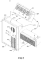
FIG. 2 is an exploded view of a temperature-regulated cabinet of the present invention; -
FIG. 3 is a partial cross-sectional view of a temperature-regulated cabinet of the present invention; -
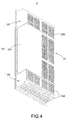
FIG. 4 is another exploded view of a temperature-regulated cabinet of the present invention; -
FIG. 5 is a schematic view of a using status of a temperature-regulated cabinet of the present invention; -
FIG. 6 is a schematic view of another using status of a temperature-regulated cabinet of the present invention; -
FIG. 7 is a schematic view of a further using status of a temperature-regulated cabinet of the present invention; and -
FIG. 8 is a schematic view of a using status of a temperature-regulated cabinet in accordance with another preferred embodiment of the present invention. - The technical contents of the present invention will become apparent with the detailed description of preferred embodiments accompanied with the illustration of related drawings as follows.
- With reference to
FIGS. 1 to 7 for a temperature-regulated cabinet of the present invention, the temperature-regulated cabinet comprises acabinet body 1 and a temperature regulatingmodule 2. - In
FIG. 1 , thecabinet body 1 may be a cold air conditioner, a hot air conditioner, a cold/hot air conditioner or a heat exchanger. Thecabinet body 1 has a containingspace 11 formed therein, and an opening 12 formed thereon and communicated with the containingspace 11. - In
FIGS. 1 to 7 , the temperature regulatingmodule 2 is detachably installed to thecabinet body 1 and covered onto theopening 12, and the temperature regulatingmodule 2 comprises atemperature regulator 21, afirst hood 22, asecond hood 23 and one ormore exhaust fans 24. - The
temperature regulator 21 comprises: acasing 211; anair outlet 212 and anair inlet 213, both configured to be corresponsive to the containingspace 11; an upperprotruding plate 214 and alower protruding plate 215, both extended from thecasing 211 and both having a plurality offirst fixing holes 216 respectively. - The
first hood 22 is detachably installed to the top of thecasing 211, and thefirst hood 22 has a plurality offirst vents 221 and a plurality ofsecond vents 222, and eachfirst vent 221 is configured to be corresponsive to the containingspace 11, and eachsecond vent 222 is exposed from thefirst hood 22 to the outside, and thefirst hood 22 has a plurality ofsecond fixing holes 25. - The
second hood 23 is detachably installed to the bottom of thecasing 211, and thesecond hood 23 has athird vent 231 and a plurality offourth vents 232, and thethird vent 231 is configured to be corresponsive to the containingspace 11, and eachfourth vent 232 is exposed from thesecond hood 23 to the outside, and thesecond hood 23 has a plurality ofsecond fixing holes 25. - In addition, the
second hood 23 includes afilter 233 installed thereon, covered onto the correspondingthird vent 231, and provided for filtering the airflow flowing into thecabinet body 1. A portion of thefourth vent 232 is formed at the bottom of thesecond hood 23, and aflap 234 is fixed to the interior of thesecond hood 23, configured to be corresponsive to thefourth vent 232 formed at the bottom of thesecond hood 23, and provided for blocking rainwater from entering into thefourth vent 232 to prevent the rainwater entering into thecabinet body 1 through thefourth vent 232 and thethird vent 231. - The
exhaust fan 24 may be installed inside one of thefirst hood 22 and thesecond hood 23. In this preferred embodiment, there areplural exhaust fans 24, and eachexhaust fan 24 is installed at eachfirst vent 221 of thefirst hood 22, and eachexhaust fan 24 has anexhaust port 241, and theexhaust ports 241 are configured to be corresponsive to thesecond vents 222 respectively. - In
FIGS. 1 to 4 , the temperature-regulatedcabinet 10 of the present invention further comprises a plurality oflocking elements 3, each passing through and being fixed to each respectivefirst fixing hole 216 and each respectivesecond fixing hole 25, so that thecasing 211, thefirst hood 22 and thesecond hood 23 may be assembled and coupled altogether. - In a preferred embodiment of the present invention, the
casing 211, thefirst hood 22 and thesecond hood 23 are jointly assembled into adoor 13, and thedoor 13 is pivotally coupled tocabinet body 1 and covered onto theopening 12. Wherein, thecasing 211, thefirst hood 22 and thesecond hood 23 are jointly assembled into one of the side boards of thecabinet body 1, but the invention is not limited to this preferred embodiment only. - In
FIGS. 5 and6 , the temperature-regulatedcabinet 10 of the present invention further comprises one or more movingboards 5, and the movingboard 5 is pivotally coupled to the interior of thefirst hood 22, disposed between theexhaust port 241 and eachsecond vent 222, and covered onto thecorresponding exhaust fan 24. - In
FIG. 1 , the temperature-regulatedcabinet 10 of the present invention further comprises afirst sensor 71, asecond sensor 72, athird sensor 73, acontroller 8 and analarm 9. - The
first sensor 71 is installed in the containingspace 11 for sensing a temperature change in thespace 11 to output an electrical signal, and thecontroller 8 is electrically coupled to thefirst sensor 71 for receiving the electrical signal to selectively turn on atemperature regulator 21 and anexhaust fan 24. - The
second sensor 72 is installed outside thecabinet body 1 for sensing a temperature change of the external air to output an electrical signal, and thecontroller 8 is electrically coupled to thesecond sensor 72 for receiving the electrical signal to selectively turn on atemperature regulator 21 and anexhaust fan 24. - The
third sensor 73 is installed in the containingspace 11 for sensing a too-high temperature or a too-low temperature in thespace 11 to output an electrical signal, and thealarm 9 is electrically coupled to thethird sensor 73 for issuing an alarm upon the receipt of the electrical signal and sending out a failure signal to notify maintenance personnel to come over and handle the situation. - With reference to
FIGS. 1 to 4 for a temperature-regulatedcabinet 10 of the present invention, thecabinet body 1 has a containingspace 11 formed therein and anopening 12 communicated with the containingspace 11. The temperature regulatingmodule 2 is detachably coupled tocabinet body 1 and covered onto thecorresponding opening 12, and thetemperature regulator 21 comprises: acasing 211; anair outlet 212 and anair inlet 213, configured to be corresponsive to the containingspace 11; afirst hood 22, detachably installed to the top of thecasing 211, and having afirst vent 221 and asecond vent 222, and thefirst vent 221 being configured to be corresponsive to the containingspace 11, and thesecond vent 222 being exposed from thefirst hood 22 to the outside; ansecond hood 23, detachably installed to the bottom of thecasing 211, and having athird vent 231 and afourth vent 232, and thethird vent 231 being configured to be corresponsive to the containingspace 11, and thefourth vent 232 being exposed from thesecond hood 23 to the outside; and anexhaust fan 24 installed inside one of thefirst hood 22 and thesecond hood 23. Thetemperature regulator 21 and thefan 24 are integrated into thesame cabinet body 1, so that the temperature-regulatedcabinet 10 may select thetemperature regulator 21 or thefan 24 to adjust the temperature inside thecabinet body 1 according to the external ambient temperature, so as to achieve the effects of simplifying the production line and lowering the installation and operation costs. - With reference to
FIGS. 5 to 7 for the using statuses of the temperature-regulatedcabinet 10 of the present invention, thetemperature regulator 21 and thefan 24 are integrated into thesame cabinet body 1, so that a base station may choose an air conditioner as a cooling device in a tropical zone, and a fan for ventilation and heat dissipation in a cold zone, and the temperature-regulatedcabinet 10 may select atemperature regulator 21 or afan 24 to adjust the temperature inside thecabinet body 1 according to the external ambient temperature, so as to achieve the effects of simplifying the production line and lowering the installation and operation costs. - In
FIGS. 1 and6 , thefirst sensor 71 is installed in the containingspace 11 for sensing the temperature inside the containingspace 11. If the sensed temperature is normal, theexhaust fan 24 will be turned on after thecontroller 8 has received an electrical signal. In -
FIGS. 1 and7 , thefirst sensor 71 is installed in the containingspace 11 for sensing the temperature inside the containingspace 11. If the sensed temperature is too high, thecontroller 8 has received an electrical signal after the electrical signal is outputted and, thetemperature regulator 21 will turn on the air conditioner. InFIGS. 1 and7 , thefirst sensor 71 is installed in the containingspace 11 for sensing the temperature inside the containingspace 11. If the sensed temperature is too low, and an electrical signal is outputted, thecontroller 8 will drive thetemperature regulator 21 to turn on the hot air conditioner after receiving the electrical signal. - In
FIGS. 1 and6 , thesecond sensor 72 is installed outside thecabinet body 1 for sensing the external air temperature. If the sensed external air temperature is too low and an electrical signal is outputted, thecontroller 8 will turn on theexhaust fan 24 after receiving the electrical signal. InFIGS. 1 and7 , thesecond sensor 72 is installed outside thecabinet body 1 for sensing an external air temperature. If the sensed external air temperature is too high, thecontroller 8 will drive thetemperature regulator 21 to turn on the cold air conditioner after receiving the electrical signal. InFIGS. 1 and7 , thesecond sensor 72 is installed outside thecabinet body 1 for sensing an external air temperature. If the sensed external air temperature is too low, and an electrical signal is outputted, thecontroller 8 will drive thetemperature regulator 21 to turn on the hot air conditioner after receiving the electrical signal. - In summation, the temperature-regulated
cabinet 10 of the present invention includes microcomputer controlled components such as afirst sensor 71, asecond sensor 72, athird sensor 73 and acontroller 8, wherein thecontroller 8 is provided for computing the temperature inside/outside thecabinet body 1 and automatically select the most appropriate operation mode for the heat dissipation according to the difference between the internal temperature and the external ambient temperature. In summer or a too-hot environment, thetemperature regulator 21 will be turned on to provide sufficient cold air to maintain a low temperature inside the cabinet. In autumn, winter, or a too-cold environment, afan 24 operated in ventilation and cooling modes dissipate the high-temperature heat from the cabinet to the outside, so as to save the power consumption for the operation of the base station. - In
FIGS. 1 to 4 , the temperature-regulatedcabinet 10 of the present invention further comprises a plurality of lockingelements 3, and an upper protrudingplate 214 and alower protruding plate 215 extended from thecasing 211 and having a plurality of first fixingholes 216 respectively, and thefirst hood 22 and thesecond hood 23 include a plurality of second fixing holes 25 respectively, and each lockingelement 3 is passed and fixed to each respectivefirst fixing hole 216 and each respective second fixinghole 25, so that thecasing 211, thefirst hood 22 and thesecond hood 23 jointly form adoor 13, and thedoor 13 is pivotally coupled to thecabinet body 1 and covered onto thecorresponding opening 12. Thecabinet body 1, thetemperature regulator 21, thefirst hood 22 and thesecond hood 23 may be assembled as a whole or detachably coupled to one another, so that if thestandalone temperature regulator 21,first hood 22, orsecond hood 23 breaks down, a new one can be removed and replaced quickly, and the present invention can reduce the maintenance procedure and time of the temperature-regulatedcabinet 10 effectively to maintain a continuous stable operation of a base station. - In
FIGS. 5 and6 , the temperature-regulatedcabinet 10 further comprises a movingboard 5 installed between theexhaust port 241 and eachsecond vent 222 and covered onto the correspondingexhaust fan 24. If theexhaust fan 24 is turned off, the movingboard 5 will cover thesecond vent 222 to maintain an internal circulation of the airflow inside thecabinet body 1. If theexhaust fan 24 is turned on, the movingboard 5 will be blown and lifted by the airflow of theexhaust port 241, so that the airflow inside thecabinet body 1 may have an external circulation situation. - With reference to
FIG. 8 for a temperature-regulatedcabinet 10 in accordance with another preferred embodiment of the present invention, this embodiment is substantially the same as the embodiments as shown inFIGS. 1 to 7 except that the temperature-regulatedcabinet 10 of this embodiment further comprises one ormore suction fans 6. - Further, the
suction fan 6 is installed at thethird vent 231, and thesuction fan 6 has anair suction port 61 configured to be corresponsive to eachfourth vent 232, so that external air may be drawn into thecabinet body 1 by thesuction fan 6, and thesuction fan 6 may be turned on or off together with theexhaust fan 24 to improve the external airflow circulation efficiency of the temperature-regulatedcabinet 10. - In summation of the description above, the temperature-regulated cabinet of the present invention is novel, useful and inventive and complies with the patent application requirements and thus is duly filed for patent application. While the invention has been described by means of specific embodiments, numerous modifications and variations could be made thereto by those skilled in the art without departing from the scope and spirit of the invention set forth in the claims.
Claims (12)
- A temperature-regulated cabinet, comprising:a cabinet body (1), having a containing space (11) formed therein, and an opening (12) communicated with the containing space (11); anda temperature regulating module (2), detachably installed onto the cabinet body (1), and configured to be corresponsive to the opening (12) to cover the opening (12), and the temperature regulating module (2) further comprising:a temperature regulator (21), having a casing (211), and an air outlet (212) and an air inlet (213) configured to be corresponsive to the containing space (11);a first hood (22), detachably installed to the top of the casing (211), and having a plurality of first vents (221) and a plurality of second vents (222), and the first vents (221) being configured to be corresponsive to the containing space (11), and the second vents (222) being exposed to the outside from the first hood (22);a second hood (23), detachably installed to the bottom of the casing (211), and having a third vent (231) and a plurality of fourth vents (232), and the third vent (231) being configured to be corresponsive to the containing space (11), and the fourth vents (232) being exposed to the outside from the second hood (23); andat least one exhaust fan (24), installed inside the first hood (22) or the second hood (23).
- The temperature-regulated cabinet as claimed in claim 1, further comprising a plurality of locking elements (3), and an upper protruding plate (214) and a lower protruding plate (215) extended from the casing (211), and the upper protruding plate (214) and the lower protruding plate (215) having a plurality of first fixing holes (216) respectively, and the first hood (22) and the second hood (23) having a plurality of second fixing holes (25) respectively, and each locking element (3) being passed and fixed to each respective first fixing hole (216) and each respective second fixing hole (25).
- The temperature-regulated cabinet as claimed in claim 1 or 2, wherein the casing (211), the first hood (22) and the second hood (23) jointly form a door (13), and the door (13) is pivotally coupled to the cabinet body (1) and configured to be corresponsive to the opening (12) to cover the opening (12).
- The temperature-regulated cabinet of any claims 1 - 3, wherein the exhaust fan (24) is installed at the first vents (221), and the exhaust fan (24) has an exhaust port (241) configured to be corresponsive to the second vents (222).
- The temperature-regulated cabinet as claimed in claim 4, further comprising at least one moving board (5), and the moving board (5) is pivotally coupled to the interior of the first hood (22) and installed between the exhaust port (241) and the second vents (222), and the moving board (5) is configured to be corresponsive to the exhaust fan (24) to cover the exhaust fan (24).
- The temperature-regulated cabinet of any claims 4 - 5, further comprising at least one suction fan (6) installed at the third vent (231), and the suction fan (6) has an air suction port (61) configured to be corresponsive to the fourth vents (232).
- The temperature-regulated cabinet of any claims 1 - 6, wherein the second hood (23) has a filter (233) installed therein and configured to be corresponsive to the third vent (231) to cover the third vent (231).
- The temperature-regulated cabinet of any claims 1 - 7, wherein the fourth vents (232) are formed at the bottom of the second hood (23), and the second hood (23) has a flap (234) fixed therein and configured to be corresponsive to the fourth vents (232).
- The temperature-regulated cabinet of any claims 1 - 8, wherein the temperature regulator (21) is a cold air conditioner, a hot air conditioner, a cold/hot air conditioner, or a heat exchanger.
- The temperature-regulated cabinet of any claims 1 - 9, further comprising a first sensor (71) and a controller (8), and the first sensor (71) being installed in the containing space (11) for sensing a temperature change in the containing space (11) to output an electrical signal, and the controller (8) being electrically coupled to the first sensor (71) for receiving the electrical signal to selectively turn on the temperature regulator (21) and the exhaust fan (24).
- The temperature-regulated cabinet of any claims 1 - 10, further comprising a second sensor (72) and a controller (8), and the second sensor (72) being installed outside the cabinet body (1) for sensing a temperature change of the external air to output an electrical signal, and the controller (8) being electrically coupled to the second sensor (72) for receiving the electrical signal to selectively turn on the temperature regulator (21) and the exhaust fan (24).
- The temperature-regulated cabinet of any claims 1 - 11, further comprising a third sensor (73) and an alarm (9), and the third sensor (73) being installed in the containing space (11) for sensing a temperature change in the containing space (11) to output an electrical signal, and the alarm (9) being electrically coupled to the third sensor (73) for receiving the electrical signal and turned on after the electrical signal is received.
Applications Claiming Priority (1)
| Application Number | Priority Date | Filing Date | Title |
|---|---|---|---|
| CN201510172000.4A CN106163217B (en) | 2015-04-13 | 2015-04-13 | Temperature adjusting cabinet |
Publications (2)
| Publication Number | Publication Date |
|---|---|
| EP3082388A1 true EP3082388A1 (en) | 2016-10-19 |
| EP3082388B1 EP3082388B1 (en) | 2018-06-20 |
Family
ID=55129615
Family Applications (1)
| Application Number | Title | Priority Date | Filing Date |
|---|---|---|---|
| EP16150981.5A Active EP3082388B1 (en) | 2015-04-13 | 2016-01-13 | Temperature regulated cabinet |
Country Status (3)
| Country | Link |
|---|---|
| US (1) | US10588244B2 (en) |
| EP (1) | EP3082388B1 (en) |
| CN (1) | CN106163217B (en) |
Cited By (1)
| Publication number | Priority date | Publication date | Assignee | Title |
|---|---|---|---|---|
| EP4404703A1 (en) * | 2023-01-17 | 2024-07-24 | Delta Electronics, Inc. | Outdoor cabinet with protective damper |
Families Citing this family (32)
| Publication number | Priority date | Publication date | Assignee | Title |
|---|---|---|---|---|
| CN106604604B (en) * | 2015-10-19 | 2019-06-28 | 鸿富锦精密电子(天津)有限公司 | Data center cooling system |
| US11249522B2 (en) * | 2016-06-30 | 2022-02-15 | Intel Corporation | Heat transfer apparatus for a computer environment |
| CN106532521A (en) * | 2016-12-09 | 2017-03-22 | 天津鼎电气成套设备股份有限公司 | Flexibly and safely usable high-low voltage switch cabinet |
| CN106684730A (en) * | 2016-12-09 | 2017-05-17 | 天津鼎电气成套设备股份有限公司 | Power distribution cabinet |
| US20180220551A1 (en) * | 2017-01-27 | 2018-08-02 | Vertiv Energy Systems, Inc. | Telecommunications equipment enclosures having heat exchangers |
| CN106973551A (en) * | 2017-04-19 | 2017-07-21 | 河南基泰电气有限公司 | A kind of switch board with electrostatic eliminating function |
| CN107425451A (en) * | 2017-08-07 | 2017-12-01 | 国网甘肃省电力公司经济技术研究院 | A kind of electrical engineering power distribution cabinet |
| US11415464B2 (en) * | 2018-04-10 | 2022-08-16 | Advancetrex Sensor Technologies Corp. | Infrared thermal monitoring system for industrial application |
| US10874036B2 (en) * | 2018-10-08 | 2020-12-22 | Delta Electronics, Inc. | Cabinet and electronic device |
| CN109195425B (en) * | 2018-11-06 | 2023-10-24 | 国网浙江省电力有限公司龙游县供电公司 | An improved heat-dissipating electrical control device |
| CN110225681A (en) * | 2019-06-15 | 2019-09-10 | 袁雷 | A kind of communication cabinet energy-saving cool-down equipment |
| CN110595522A (en) * | 2019-10-28 | 2019-12-20 | 安徽天康(集团)股份有限公司 | Automatic constant temperature instrument cabinet |
| CN113253818A (en) * | 2020-02-07 | 2021-08-13 | 施耐德电气It公司 | Selective rack cooling based on external temperature |
| US11246241B1 (en) * | 2020-03-04 | 2022-02-08 | Amazon Technologies, Inc. | Movable media air handling unit |
| CN111511165A (en) * | 2020-04-16 | 2020-08-07 | 宝鸡文理学院 | Thing networking signal reception terminal controlgear |
| CN112616275A (en) * | 2020-12-07 | 2021-04-06 | 张彦生 | Electrical control cabinet |
| CN114629020A (en) * | 2020-12-10 | 2022-06-14 | 武威电建实业有限公司 | Little small-size many first little electric wire netting switch boards |
| US11350534B1 (en) * | 2020-12-10 | 2022-05-31 | Super Micro Computer, Inc. | Telecommunication cabinet with replaceable cabinet door module |
| US11445633B2 (en) * | 2021-01-14 | 2022-09-13 | Super Micro Computer, Inc. | Telecommunication cabinet with hidden anti-theft heat dissipation module |
| US11178792B1 (en) * | 2021-01-28 | 2021-11-16 | Super Micro Computer, Inc. | Heat exchange structure of telecommunication cabinet |
| CN113040528B (en) * | 2021-04-01 | 2022-09-13 | 温州智点信息科技有限公司 | RFID digital intelligent safety tool cabinet |
| CN113301771B (en) * | 2021-04-07 | 2024-04-09 | 华为数字能源技术有限公司 | A multi-temperature control cabinet and a scheduling method thereof |
| CN113784593B (en) * | 2021-09-13 | 2023-07-18 | 安徽飞凯电子技术有限公司 | An assembled cooling cabinet and its working method |
| CN114071926B (en) * | 2021-11-27 | 2022-07-08 | 深圳市天技电子技术有限公司 | Electric power module mounting structure convenient to joint is difficult for rocking |
| CN114190058B (en) * | 2021-12-09 | 2024-10-01 | 中通服节能技术服务有限公司 | Energy-saving control micro-module data center |
| US20250183464A1 (en) * | 2021-12-31 | 2025-06-05 | Powin, Llc | Energy storage systems and associated methods |
| CN114585247B (en) * | 2022-05-09 | 2022-08-05 | 浙江德塔森特数据技术有限公司 | AI analysis-based energy-saving control method for data machine room |
| CN115003137B (en) * | 2022-07-22 | 2024-11-19 | 中国建筑西南设计研究院有限公司 | A ventilation base station cabinet considering temperature non-uniformity and its operation control method |
| CN116017963B (en) * | 2023-03-28 | 2023-06-16 | 浙江德塔森特数据技术有限公司 | Intelligent regulation cabinet refrigerating capacity regulating method and intelligent regulation cabinet |
| CN116347878B (en) * | 2023-05-30 | 2023-08-08 | 山西潞安安易电气有限公司 | Heat abstractor of mining alternating current frequency converter |
| CN116544827B (en) * | 2023-07-07 | 2024-01-09 | 希格玛电气(珠海)有限公司 | Full-closed complete switch cabinet detection device and detection method |
| CN118426518B (en) * | 2024-07-04 | 2024-10-22 | 深圳市派宝智能有限公司 | Temperature control device of intelligent cloud cabinet based on internet of things |
Citations (2)
| Publication number | Priority date | Publication date | Assignee | Title |
|---|---|---|---|---|
| US20010052412A1 (en) * | 1999-08-20 | 2001-12-20 | Harri Tikka | Cooling system for a cabinet |
| WO2010009626A1 (en) * | 2008-07-25 | 2010-01-28 | 华为技术有限公司 | A heat exchanger and a communication device |
Family Cites Families (13)
| Publication number | Priority date | Publication date | Assignee | Title |
|---|---|---|---|---|
| DE3045326C2 (en) * | 1980-12-02 | 1982-10-21 | Autz & Hermann, 6900 Heidelberg | Heat exchanger used for dust-free cooling of a switch cabinet |
| SE438061B (en) * | 1984-02-01 | 1985-03-25 | Thermo Produkter B S Ab | KYLANLEGGNING |
| JP2001099531A (en) * | 1999-09-29 | 2001-04-13 | Denso Corp | Cooling system |
| JP4200634B2 (en) * | 2000-04-20 | 2008-12-24 | 株式会社デンソー | Cooling system |
| US7104081B2 (en) * | 2004-03-30 | 2006-09-12 | International Business Machines Corproation | Condensate removal system and method for facilitating cooling of an electronics system |
| US8051672B2 (en) * | 2007-08-30 | 2011-11-08 | Afco Systems | Fluid cooled cabinet for electronic equipment |
| CN102090160B (en) * | 2008-07-09 | 2013-11-27 | 松下电器产业株式会社 | Cooling device for heater storage device, and heater storage device using same |
| US20120298330A1 (en) * | 2010-11-19 | 2012-11-29 | Purcell Systems, Inc. | Air path rain guard for a cooling system of a weatherproof enclosure for electrical equipment and the like |
| TWI405945B (en) * | 2010-12-23 | 2013-08-21 | Delta Electronics Inc | Air-cooling heat exchanger and electronic equipment employing same |
| US20120298341A1 (en) * | 2011-05-27 | 2012-11-29 | Futurewei Technologies, Inc. | System and Method for Isolating Components in an Enclosure |
| CN203190538U (en) * | 2013-03-06 | 2013-09-11 | 苏州昆拓热控系统股份有限公司 | Cabinet air conditioner |
| CN203708732U (en) * | 2013-12-04 | 2014-07-09 | 曾国辉 | Air conditioner for equipment cabinet and equipment cabinet |
| CN204498544U (en) * | 2015-04-13 | 2015-07-22 | 台达电子工业股份有限公司 | Temperature control cabinet |
-
2015
- 2015-04-13 CN CN201510172000.4A patent/CN106163217B/en active Active
- 2015-11-24 US US14/950,379 patent/US10588244B2/en active Active
-
2016
- 2016-01-13 EP EP16150981.5A patent/EP3082388B1/en active Active
Patent Citations (2)
| Publication number | Priority date | Publication date | Assignee | Title |
|---|---|---|---|---|
| US20010052412A1 (en) * | 1999-08-20 | 2001-12-20 | Harri Tikka | Cooling system for a cabinet |
| WO2010009626A1 (en) * | 2008-07-25 | 2010-01-28 | 华为技术有限公司 | A heat exchanger and a communication device |
Cited By (1)
| Publication number | Priority date | Publication date | Assignee | Title |
|---|---|---|---|---|
| EP4404703A1 (en) * | 2023-01-17 | 2024-07-24 | Delta Electronics, Inc. | Outdoor cabinet with protective damper |
Also Published As
| Publication number | Publication date |
|---|---|
| US20160302326A1 (en) | 2016-10-13 |
| CN106163217B (en) | 2020-06-26 |
| EP3082388B1 (en) | 2018-06-20 |
| CN106163217A (en) | 2016-11-23 |
| US10588244B2 (en) | 2020-03-10 |
Similar Documents
| Publication | Publication Date | Title |
|---|---|---|
| EP3082388B1 (en) | Temperature regulated cabinet | |
| JP4920739B2 (en) | Exhaust removal system | |
| CN105578835B (en) | Container data center | |
| CN1852648A (en) | Machine-cabinet temperature controlling system, device and method | |
| TWI608333B (en) | Combined data center and its heat dissipation method | |
| WO2007095846A1 (en) | Temperature control device, management device, system and method | |
| US20130189916A1 (en) | Rack system and ventilation apparatus thereof | |
| CN102388684A (en) | An electronic equipment cabinet | |
| US20140319984A1 (en) | Cabinet ventilation system | |
| CN107172839A (en) | A kind of integral intelligent rack | |
| WO2016053227A1 (en) | Fan controlled ambient air cooling of equipment in a controlled airflow environment | |
| CN105392339A (en) | Electrical cabinet heat radiating device and electrical cabinet using same | |
| CN108826464A (en) | Ceiling machine | |
| CN108155571A (en) | A kind of stable low voltage equipment of high heat dissipation | |
| CN104251522A (en) | Air conditioner electrical box assembly and air conditioner outdoor unit thereof | |
| CN217009984U (en) | Switch board with heat dissipation dehumidification function | |
| EP3327362B1 (en) | Outdoor unit of air conditioner | |
| CN115507441A (en) | Heat dissipation structure of electric appliance box, indoor unit, base station air conditioner and method | |
| CN107135631A (en) | A kind of water proof and dust proof regulator cubicle with heat sinking function | |
| CN203810590U (en) | Air conditioning electric control box cooling device and air conditioning comprising same | |
| JPWO2017149766A1 (en) | Electrical component module and air conditioner outdoor unit | |
| CN209882406U (en) | Cabinet type data center temperature control device and cabinet type data center device | |
| CN204498544U (en) | Temperature control cabinet | |
| CN102694348B (en) | The thermal management algorithm and device for implementing the method for power-converting device | |
| CN114269090A (en) | an outdoor cabinet |
Legal Events
| Date | Code | Title | Description |
|---|---|---|---|
| PUAI | Public reference made under article 153(3) epc to a published international application that has entered the european phase |
Free format text: ORIGINAL CODE: 0009012 |
|
| AK | Designated contracting states |
Kind code of ref document: A1 Designated state(s): AL AT BE BG CH CY CZ DE DK EE ES FI FR GB GR HR HU IE IS IT LI LT LU LV MC MK MT NL NO PL PT RO RS SE SI SK SM TR |
|
| AX | Request for extension of the european patent |
Extension state: BA ME |
|
| STAA | Information on the status of an ep patent application or granted ep patent |
Free format text: STATUS: REQUEST FOR EXAMINATION WAS MADE |
|
| 17P | Request for examination filed |
Effective date: 20170419 |
|
| RBV | Designated contracting states (corrected) |
Designated state(s): AL AT BE BG CH CY CZ DE DK EE ES FI FR GB GR HR HU IE IS IT LI LT LU LV MC MK MT NL NO PL PT RO RS SE SI SK SM TR |
|
| GRAP | Despatch of communication of intention to grant a patent |
Free format text: ORIGINAL CODE: EPIDOSNIGR1 |
|
| STAA | Information on the status of an ep patent application or granted ep patent |
Free format text: STATUS: GRANT OF PATENT IS INTENDED |
|
| INTG | Intention to grant announced |
Effective date: 20180112 |
|
| RIN1 | Information on inventor provided before grant (corrected) |
Inventor name: WU, JIAN-JHANG Inventor name: HUNG, CHUN-YANG Inventor name: CHEN, LEE-LONG Inventor name: CHEN, CHIA-WEI |
|
| GRAS | Grant fee paid |
Free format text: ORIGINAL CODE: EPIDOSNIGR3 |
|
| GRAA | (expected) grant |
Free format text: ORIGINAL CODE: 0009210 |
|
| STAA | Information on the status of an ep patent application or granted ep patent |
Free format text: STATUS: THE PATENT HAS BEEN GRANTED |
|
| AK | Designated contracting states |
Kind code of ref document: B1 Designated state(s): AL AT BE BG CH CY CZ DE DK EE ES FI FR GB GR HR HU IE IS IT LI LT LU LV MC MK MT NL NO PL PT RO RS SE SI SK SM TR |
|
| REG | Reference to a national code |
Ref country code: GB Ref legal event code: FG4D |
|
| REG | Reference to a national code |
Ref country code: IE Ref legal event code: FG4D |
|
| REG | Reference to a national code |
Ref country code: AT Ref legal event code: REF Ref document number: 1011474 Country of ref document: AT Kind code of ref document: T Effective date: 20180715 |
|
| REG | Reference to a national code |
Ref country code: DE Ref legal event code: R096 Ref document number: 602016003592 Country of ref document: DE |
|
| REG | Reference to a national code |
Ref country code: NL Ref legal event code: MP Effective date: 20180620 |
|
| PG25 | Lapsed in a contracting state [announced via postgrant information from national office to epo] |
Ref country code: LT Free format text: LAPSE BECAUSE OF FAILURE TO SUBMIT A TRANSLATION OF THE DESCRIPTION OR TO PAY THE FEE WITHIN THE PRESCRIBED TIME-LIMIT Effective date: 20180620 Ref country code: NO Free format text: LAPSE BECAUSE OF FAILURE TO SUBMIT A TRANSLATION OF THE DESCRIPTION OR TO PAY THE FEE WITHIN THE PRESCRIBED TIME-LIMIT Effective date: 20180920 Ref country code: SE Free format text: LAPSE BECAUSE OF FAILURE TO SUBMIT A TRANSLATION OF THE DESCRIPTION OR TO PAY THE FEE WITHIN THE PRESCRIBED TIME-LIMIT Effective date: 20180620 Ref country code: BG Free format text: LAPSE BECAUSE OF FAILURE TO SUBMIT A TRANSLATION OF THE DESCRIPTION OR TO PAY THE FEE WITHIN THE PRESCRIBED TIME-LIMIT Effective date: 20180920 Ref country code: FI Free format text: LAPSE BECAUSE OF FAILURE TO SUBMIT A TRANSLATION OF THE DESCRIPTION OR TO PAY THE FEE WITHIN THE PRESCRIBED TIME-LIMIT Effective date: 20180620 |
|
| REG | Reference to a national code |
Ref country code: LT Ref legal event code: MG4D |
|
| PG25 | Lapsed in a contracting state [announced via postgrant information from national office to epo] |
Ref country code: HR Free format text: LAPSE BECAUSE OF FAILURE TO SUBMIT A TRANSLATION OF THE DESCRIPTION OR TO PAY THE FEE WITHIN THE PRESCRIBED TIME-LIMIT Effective date: 20180620 Ref country code: GR Free format text: LAPSE BECAUSE OF FAILURE TO SUBMIT A TRANSLATION OF THE DESCRIPTION OR TO PAY THE FEE WITHIN THE PRESCRIBED TIME-LIMIT Effective date: 20180921 Ref country code: LV Free format text: LAPSE BECAUSE OF FAILURE TO SUBMIT A TRANSLATION OF THE DESCRIPTION OR TO PAY THE FEE WITHIN THE PRESCRIBED TIME-LIMIT Effective date: 20180620 Ref country code: RS Free format text: LAPSE BECAUSE OF FAILURE TO SUBMIT A TRANSLATION OF THE DESCRIPTION OR TO PAY THE FEE WITHIN THE PRESCRIBED TIME-LIMIT Effective date: 20180620 |
|
| REG | Reference to a national code |
Ref country code: AT Ref legal event code: MK05 Ref document number: 1011474 Country of ref document: AT Kind code of ref document: T Effective date: 20180620 |
|
| PG25 | Lapsed in a contracting state [announced via postgrant information from national office to epo] |
Ref country code: NL Free format text: LAPSE BECAUSE OF FAILURE TO SUBMIT A TRANSLATION OF THE DESCRIPTION OR TO PAY THE FEE WITHIN THE PRESCRIBED TIME-LIMIT Effective date: 20180620 |
|
| PG25 | Lapsed in a contracting state [announced via postgrant information from national office to epo] |
Ref country code: RO Free format text: LAPSE BECAUSE OF FAILURE TO SUBMIT A TRANSLATION OF THE DESCRIPTION OR TO PAY THE FEE WITHIN THE PRESCRIBED TIME-LIMIT Effective date: 20180620 Ref country code: CZ Free format text: LAPSE BECAUSE OF FAILURE TO SUBMIT A TRANSLATION OF THE DESCRIPTION OR TO PAY THE FEE WITHIN THE PRESCRIBED TIME-LIMIT Effective date: 20180620 Ref country code: PL Free format text: LAPSE BECAUSE OF FAILURE TO SUBMIT A TRANSLATION OF THE DESCRIPTION OR TO PAY THE FEE WITHIN THE PRESCRIBED TIME-LIMIT Effective date: 20180620 Ref country code: SK Free format text: LAPSE BECAUSE OF FAILURE TO SUBMIT A TRANSLATION OF THE DESCRIPTION OR TO PAY THE FEE WITHIN THE PRESCRIBED TIME-LIMIT Effective date: 20180620 Ref country code: AT Free format text: LAPSE BECAUSE OF FAILURE TO SUBMIT A TRANSLATION OF THE DESCRIPTION OR TO PAY THE FEE WITHIN THE PRESCRIBED TIME-LIMIT Effective date: 20180620 Ref country code: IS Free format text: LAPSE BECAUSE OF FAILURE TO SUBMIT A TRANSLATION OF THE DESCRIPTION OR TO PAY THE FEE WITHIN THE PRESCRIBED TIME-LIMIT Effective date: 20181020 Ref country code: EE Free format text: LAPSE BECAUSE OF FAILURE TO SUBMIT A TRANSLATION OF THE DESCRIPTION OR TO PAY THE FEE WITHIN THE PRESCRIBED TIME-LIMIT Effective date: 20180620 |
|
| PG25 | Lapsed in a contracting state [announced via postgrant information from national office to epo] |
Ref country code: IT Free format text: LAPSE BECAUSE OF FAILURE TO SUBMIT A TRANSLATION OF THE DESCRIPTION OR TO PAY THE FEE WITHIN THE PRESCRIBED TIME-LIMIT Effective date: 20180620 Ref country code: ES Free format text: LAPSE BECAUSE OF FAILURE TO SUBMIT A TRANSLATION OF THE DESCRIPTION OR TO PAY THE FEE WITHIN THE PRESCRIBED TIME-LIMIT Effective date: 20180620 Ref country code: SM Free format text: LAPSE BECAUSE OF FAILURE TO SUBMIT A TRANSLATION OF THE DESCRIPTION OR TO PAY THE FEE WITHIN THE PRESCRIBED TIME-LIMIT Effective date: 20180620 |
|
| REG | Reference to a national code |
Ref country code: DE Ref legal event code: R097 Ref document number: 602016003592 Country of ref document: DE |
|
| PLBE | No opposition filed within time limit |
Free format text: ORIGINAL CODE: 0009261 |
|
| STAA | Information on the status of an ep patent application or granted ep patent |
Free format text: STATUS: NO OPPOSITION FILED WITHIN TIME LIMIT |
|
| 26N | No opposition filed |
Effective date: 20190321 |
|
| PG25 | Lapsed in a contracting state [announced via postgrant information from national office to epo] |
Ref country code: DK Free format text: LAPSE BECAUSE OF FAILURE TO SUBMIT A TRANSLATION OF THE DESCRIPTION OR TO PAY THE FEE WITHIN THE PRESCRIBED TIME-LIMIT Effective date: 20180620 |
|
| PG25 | Lapsed in a contracting state [announced via postgrant information from national office to epo] |
Ref country code: SI Free format text: LAPSE BECAUSE OF FAILURE TO SUBMIT A TRANSLATION OF THE DESCRIPTION OR TO PAY THE FEE WITHIN THE PRESCRIBED TIME-LIMIT Effective date: 20180620 Ref country code: MC Free format text: LAPSE BECAUSE OF FAILURE TO SUBMIT A TRANSLATION OF THE DESCRIPTION OR TO PAY THE FEE WITHIN THE PRESCRIBED TIME-LIMIT Effective date: 20180620 |
|
| REG | Reference to a national code |
Ref country code: CH Ref legal event code: PL |
|
| PG25 | Lapsed in a contracting state [announced via postgrant information from national office to epo] |
Ref country code: LU Free format text: LAPSE BECAUSE OF NON-PAYMENT OF DUE FEES Effective date: 20190113 |
|
| REG | Reference to a national code |
Ref country code: BE Ref legal event code: MM Effective date: 20190131 |
|
| REG | Reference to a national code |
Ref country code: IE Ref legal event code: MM4A |
|
| PG25 | Lapsed in a contracting state [announced via postgrant information from national office to epo] |
Ref country code: FR Free format text: LAPSE BECAUSE OF NON-PAYMENT OF DUE FEES Effective date: 20190131 |
|
| PG25 | Lapsed in a contracting state [announced via postgrant information from national office to epo] |
Ref country code: BE Free format text: LAPSE BECAUSE OF NON-PAYMENT OF DUE FEES Effective date: 20190131 Ref country code: AL Free format text: LAPSE BECAUSE OF FAILURE TO SUBMIT A TRANSLATION OF THE DESCRIPTION OR TO PAY THE FEE WITHIN THE PRESCRIBED TIME-LIMIT Effective date: 20180620 |
|
| PG25 | Lapsed in a contracting state [announced via postgrant information from national office to epo] |
Ref country code: CH Free format text: LAPSE BECAUSE OF NON-PAYMENT OF DUE FEES Effective date: 20190131 Ref country code: LI Free format text: LAPSE BECAUSE OF NON-PAYMENT OF DUE FEES Effective date: 20190131 |
|
| PG25 | Lapsed in a contracting state [announced via postgrant information from national office to epo] |
Ref country code: IE Free format text: LAPSE BECAUSE OF NON-PAYMENT OF DUE FEES Effective date: 20190113 |
|
| PG25 | Lapsed in a contracting state [announced via postgrant information from national office to epo] |
Ref country code: TR Free format text: LAPSE BECAUSE OF FAILURE TO SUBMIT A TRANSLATION OF THE DESCRIPTION OR TO PAY THE FEE WITHIN THE PRESCRIBED TIME-LIMIT Effective date: 20180620 |
|
| PG25 | Lapsed in a contracting state [announced via postgrant information from national office to epo] |
Ref country code: MT Free format text: LAPSE BECAUSE OF NON-PAYMENT OF DUE FEES Effective date: 20190113 Ref country code: PT Free format text: LAPSE BECAUSE OF FAILURE TO SUBMIT A TRANSLATION OF THE DESCRIPTION OR TO PAY THE FEE WITHIN THE PRESCRIBED TIME-LIMIT Effective date: 20181022 |
|
| GBPC | Gb: european patent ceased through non-payment of renewal fee |
Effective date: 20200113 |
|
| PG25 | Lapsed in a contracting state [announced via postgrant information from national office to epo] |
Ref country code: GB Free format text: LAPSE BECAUSE OF NON-PAYMENT OF DUE FEES Effective date: 20200113 |
|
| PG25 | Lapsed in a contracting state [announced via postgrant information from national office to epo] |
Ref country code: CY Free format text: LAPSE BECAUSE OF FAILURE TO SUBMIT A TRANSLATION OF THE DESCRIPTION OR TO PAY THE FEE WITHIN THE PRESCRIBED TIME-LIMIT Effective date: 20180620 |
|
| PG25 | Lapsed in a contracting state [announced via postgrant information from national office to epo] |
Ref country code: HU Free format text: LAPSE BECAUSE OF FAILURE TO SUBMIT A TRANSLATION OF THE DESCRIPTION OR TO PAY THE FEE WITHIN THE PRESCRIBED TIME-LIMIT; INVALID AB INITIO Effective date: 20160113 |
|
| PG25 | Lapsed in a contracting state [announced via postgrant information from national office to epo] |
Ref country code: MK Free format text: LAPSE BECAUSE OF FAILURE TO SUBMIT A TRANSLATION OF THE DESCRIPTION OR TO PAY THE FEE WITHIN THE PRESCRIBED TIME-LIMIT Effective date: 20180620 |
|
| PGFP | Annual fee paid to national office [announced via postgrant information from national office to epo] |
Ref country code: DE Payment date: 20260128 Year of fee payment: 11 |