EP3082329A1 - Image reading device and image forming apparatus with original size detection taking into account a shadow cast by an original. - Google Patents
Image reading device and image forming apparatus with original size detection taking into account a shadow cast by an original. Download PDFInfo
- Publication number
- EP3082329A1 EP3082329A1 EP16164875.3A EP16164875A EP3082329A1 EP 3082329 A1 EP3082329 A1 EP 3082329A1 EP 16164875 A EP16164875 A EP 16164875A EP 3082329 A1 EP3082329 A1 EP 3082329A1
- Authority
- EP
- European Patent Office
- Prior art keywords
- pixel
- document
- image
- image data
- lines
- Prior art date
- Legal status (The legal status is an assumption and is not a legal conclusion. Google has not performed a legal analysis and makes no representation as to the accuracy of the status listed.)
- Ceased
Links
- 238000001514 detection method Methods 0.000 title claims abstract description 56
- 238000012545 processing Methods 0.000 claims abstract description 77
- 238000000034 method Methods 0.000 claims description 22
- 238000003825 pressing Methods 0.000 claims description 14
- 238000003860 storage Methods 0.000 claims description 13
- 230000003760 hair shine Effects 0.000 claims description 3
- 230000032258 transport Effects 0.000 description 30
- 239000011521 glass Substances 0.000 description 28
- 230000002093 peripheral effect Effects 0.000 description 25
- 238000010586 diagram Methods 0.000 description 10
- 238000007639 printing Methods 0.000 description 8
- 238000006243 chemical reaction Methods 0.000 description 6
- 238000002360 preparation method Methods 0.000 description 5
- 238000004804 winding Methods 0.000 description 5
- 238000004891 communication Methods 0.000 description 3
- 239000002689 soil Substances 0.000 description 3
- 230000006870 function Effects 0.000 description 2
- 238000012546 transfer Methods 0.000 description 2
- 230000003321 amplification Effects 0.000 description 1
- 238000003705 background correction Methods 0.000 description 1
- 238000004140 cleaning Methods 0.000 description 1
- 238000010276 construction Methods 0.000 description 1
- 238000012937 correction Methods 0.000 description 1
- 238000003708 edge detection Methods 0.000 description 1
- 230000012447 hatching Effects 0.000 description 1
- 238000010438 heat treatment Methods 0.000 description 1
- 238000012986 modification Methods 0.000 description 1
- 230000004048 modification Effects 0.000 description 1
- 238000003199 nucleic acid amplification method Methods 0.000 description 1
Images




Classifications
-
- H—ELECTRICITY
- H04—ELECTRIC COMMUNICATION TECHNIQUE
- H04N—PICTORIAL COMMUNICATION, e.g. TELEVISION
- H04N1/00—Scanning, transmission or reproduction of documents or the like, e.g. facsimile transmission; Details thereof
- H04N1/00681—Detecting the presence, position or size of a sheet or correcting its position before scanning
- H04N1/00729—Detection means
- H04N1/00734—Optical detectors
- H04N1/00737—Optical detectors using the scanning elements as detectors
-
- H—ELECTRICITY
- H04—ELECTRIC COMMUNICATION TECHNIQUE
- H04N—PICTORIAL COMMUNICATION, e.g. TELEVISION
- H04N1/00—Scanning, transmission or reproduction of documents or the like, e.g. facsimile transmission; Details thereof
- H04N1/00681—Detecting the presence, position or size of a sheet or correcting its position before scanning
- H04N1/00684—Object of the detection
- H04N1/00708—Size or dimensions
-
- H—ELECTRICITY
- H04—ELECTRIC COMMUNICATION TECHNIQUE
- H04N—PICTORIAL COMMUNICATION, e.g. TELEVISION
- H04N1/00—Scanning, transmission or reproduction of documents or the like, e.g. facsimile transmission; Details thereof
- H04N1/00681—Detecting the presence, position or size of a sheet or correcting its position before scanning
- H04N1/00684—Object of the detection
- H04N1/00708—Size or dimensions
- H04N1/0071—Width
-
- H—ELECTRICITY
- H04—ELECTRIC COMMUNICATION TECHNIQUE
- H04N—PICTORIAL COMMUNICATION, e.g. TELEVISION
- H04N1/00—Scanning, transmission or reproduction of documents or the like, e.g. facsimile transmission; Details thereof
- H04N1/00681—Detecting the presence, position or size of a sheet or correcting its position before scanning
- H04N1/00684—Object of the detection
- H04N1/00708—Size or dimensions
- H04N1/00713—Length
-
- H—ELECTRICITY
- H04—ELECTRIC COMMUNICATION TECHNIQUE
- H04N—PICTORIAL COMMUNICATION, e.g. TELEVISION
- H04N1/00—Scanning, transmission or reproduction of documents or the like, e.g. facsimile transmission; Details thereof
- H04N1/00681—Detecting the presence, position or size of a sheet or correcting its position before scanning
- H04N1/00684—Object of the detection
- H04N1/00708—Size or dimensions
- H04N1/00716—Thickness
-
- H—ELECTRICITY
- H04—ELECTRIC COMMUNICATION TECHNIQUE
- H04N—PICTORIAL COMMUNICATION, e.g. TELEVISION
- H04N1/00—Scanning, transmission or reproduction of documents or the like, e.g. facsimile transmission; Details thereof
- H04N1/00681—Detecting the presence, position or size of a sheet or correcting its position before scanning
- H04N1/00742—Detection methods
- H04N1/00748—Detecting edges, e.g. of a stationary sheet
-
- H—ELECTRICITY
- H04—ELECTRIC COMMUNICATION TECHNIQUE
- H04N—PICTORIAL COMMUNICATION, e.g. TELEVISION
- H04N1/00—Scanning, transmission or reproduction of documents or the like, e.g. facsimile transmission; Details thereof
- H04N1/00681—Detecting the presence, position or size of a sheet or correcting its position before scanning
- H04N1/00742—Detection methods
- H04N1/0075—Detecting a change in reflectivity
- H04N1/00753—Detecting a change in reflectivity of a sheet relative to a particular backgroud
-
- H—ELECTRICITY
- H04—ELECTRIC COMMUNICATION TECHNIQUE
- H04N—PICTORIAL COMMUNICATION, e.g. TELEVISION
- H04N1/00—Scanning, transmission or reproduction of documents or the like, e.g. facsimile transmission; Details thereof
- H04N1/00681—Detecting the presence, position or size of a sheet or correcting its position before scanning
- H04N1/00763—Action taken as a result of detection
- H04N1/00766—Storing data
-
- H—ELECTRICITY
- H04—ELECTRIC COMMUNICATION TECHNIQUE
- H04N—PICTORIAL COMMUNICATION, e.g. TELEVISION
- H04N1/00—Scanning, transmission or reproduction of documents or the like, e.g. facsimile transmission; Details thereof
- H04N1/00681—Detecting the presence, position or size of a sheet or correcting its position before scanning
- H04N1/00763—Action taken as a result of detection
- H04N1/00769—Comparing, e.g. with threshold
-
- H—ELECTRICITY
- H04—ELECTRIC COMMUNICATION TECHNIQUE
- H04N—PICTORIAL COMMUNICATION, e.g. TELEVISION
- H04N1/00—Scanning, transmission or reproduction of documents or the like, e.g. facsimile transmission; Details thereof
- H04N1/00681—Detecting the presence, position or size of a sheet or correcting its position before scanning
- H04N1/00763—Action taken as a result of detection
- H04N1/00774—Adjusting or controlling
- H04N1/00779—Adjusting settings, e.g. mode, feeding rate or type of paper
-
- H—ELECTRICITY
- H04—ELECTRIC COMMUNICATION TECHNIQUE
- H04N—PICTORIAL COMMUNICATION, e.g. TELEVISION
- H04N1/00—Scanning, transmission or reproduction of documents or the like, e.g. facsimile transmission; Details thereof
- H04N1/00795—Reading arrangements
- H04N1/00798—Circuits or arrangements for the control thereof, e.g. using a programmed control device or according to a measured quantity
- H04N1/00816—Determining the reading area, e.g. eliminating reading of margins
-
- H—ELECTRICITY
- H04—ELECTRIC COMMUNICATION TECHNIQUE
- H04N—PICTORIAL COMMUNICATION, e.g. TELEVISION
- H04N1/00—Scanning, transmission or reproduction of documents or the like, e.g. facsimile transmission; Details thereof
- H04N1/00795—Reading arrangements
- H04N1/00827—Arrangements for reading an image from an unusual original, e.g. 3-dimensional objects
-
- H—ELECTRICITY
- H04—ELECTRIC COMMUNICATION TECHNIQUE
- H04N—PICTORIAL COMMUNICATION, e.g. TELEVISION
- H04N1/00—Scanning, transmission or reproduction of documents or the like, e.g. facsimile transmission; Details thereof
- H04N1/04—Scanning arrangements, i.e. arrangements for the displacement of active reading or reproducing elements relative to the original or reproducing medium, or vice versa
- H04N1/10—Scanning arrangements, i.e. arrangements for the displacement of active reading or reproducing elements relative to the original or reproducing medium, or vice versa using flat picture-bearing surfaces
- H04N1/1013—Scanning arrangements, i.e. arrangements for the displacement of active reading or reproducing elements relative to the original or reproducing medium, or vice versa using flat picture-bearing surfaces with sub-scanning by translatory movement of at least a part of the main-scanning components
-
- H—ELECTRICITY
- H04—ELECTRIC COMMUNICATION TECHNIQUE
- H04N—PICTORIAL COMMUNICATION, e.g. TELEVISION
- H04N2201/00—Indexing scheme relating to scanning, transmission or reproduction of documents or the like, and to details thereof
- H04N2201/0077—Types of the still picture apparatus
- H04N2201/0094—Multifunctional device, i.e. a device capable of all of reading, reproducing, copying, facsimile transception, file transception
-
- H—ELECTRICITY
- H04—ELECTRIC COMMUNICATION TECHNIQUE
- H04N—PICTORIAL COMMUNICATION, e.g. TELEVISION
- H04N2201/00—Indexing scheme relating to scanning, transmission or reproduction of documents or the like, and to details thereof
- H04N2201/04—Scanning arrangements
- H04N2201/0402—Arrangements not specific to a particular one of the scanning methods covered by groups H04N1/04 - H04N1/207
- H04N2201/0422—Media holders, covers, supports, backgrounds; Arrangements to facilitate placing of the medium
Definitions
- the present disclosure relates to an image reading device and an image forming apparatus.
- a document as a reading target is placed on a document stage, and the document placed on the document stage is held by a document cover. Then, when reading the document placed on the document stage, the image reading device radiates light toward the document stage, focuses the light reflected from the document and from the document cover on an image sensor, and generates image data based on an analog signal output from the image sensor.
- the image data (read image data) generated as described above includes image data of the document and image data of the document cover.
- size detection of the document is often performed based on the read image data.
- an edge of a document is detected by discriminating, from the read image data, black lines (lines of pixels corresponding to a shadow) that appear as a result of a shadow cast in the vicinity of an edge of the document being read.
- an image reading device includes an image reading portion, an image processing portion, and a storage.
- the image reading portion shines light on a predetermined reading region including a region where a document is present, and reads the reading region.
- the image processing portion generates image data of the reading region read by the image reading portion, detects the size of the document based on the image data of the reading region, performs image processing on the image data of the reading region based on the size of the document, and outputs the processed image data.
- the storage stores size information that is information in which the vertical and horizontal dimensions for each of a plurality of kinds of reference sizes are defined.
- the image reading portion performs reading of the reading region with the document set in the reading region such that two edges of the document are aligned with reference lines that extend in the main and sub scanning directions.
- the image processing portion generates, as the image data of the reading region, image data for output and image data for size detection, the image data for size detection having a lower resolution than the output image data.
- the image processing portion discriminates, from the image data for size detection, high density lines, the high density lines being lines of pixels that appear as a result of a shadow cast in the vicinity of an edge of the document that does not overlap the reference lines being read, the high density lines extending in one direction out of the main and sub scanning directions.
- the image processing portion performs a target line setting process to set one of the high density lines as a target line.
- the image processing portion calculates as a width for size detection a width from, out of the reference lines that extend in the main and sub scanning directions, a reference line that extends in the one direction out of the main and sub scanning directions to the target line.
- the image processing portion sets as the size of the document a reference size having a width closest to the width for size detection out of the plurality of kinds of the reference sizes.
- the image processing portion performs image processing on the image data for output based on the reference size set as the size of the document, and outputs the processed image data.
- an image forming apparatus includes the image reading device described above.
- the multifunction peripheral 100 is provided with an image reading portion 1 including a document transport unit 11.
- the multifunction peripheral 100 corresponds to an "image reading device” and an "image forming apparatus”.
- the image reading portion 1 has a frame having, fitted in it, a contact glass la for placement reading and a contact glass 1b for transport reading.
- the image reading portion 1 performs placement reading to read a document placed on the contact glass 1a and performs transport reading to read a document D passing across the contact glass 1b. In transport reading, a document is transported across the contact glass 1b by the document transport unit 11.
- the image reading portion 1 includes a light source 12, an image sensor 13, a mirror 14, and a lens 15, and reads a document optically. These components that constitute the image reading portion 1 are arranged inside the frame of the image reading portion 1.
- the light source 12 comprises a plurality of LED (light-emitting diode) elements and generates light with which a document is irradiated.
- the plurality of LED elements are arranged in a row extending in the main scanning direction.
- the light source 12 radiates light toward the contact glass 1a (the light that has been transmitted through the contact glass 1a illuminates the document).
- the contact glass 1b the light that has been transmitted through the contact glass 1b illuminates the document.
- the light reflected from the document is then reflected on the mirror 14 so as to be guided into the lens 15.
- the lens 15 converges the reflected light.
- the image sensor 13 reads a document line-by-line by receiving the light reflected from the document (the light converged through the lens 15).
- This image sensor 13 comprises a CCD (charge coupled device) having a plurality of photoelectric conversion elements arranged in a row extending in the main scanning direction.
- the image sensor 13, on receiving the reflected light, performs photoelectric conversion and stores electric charge for each pixel, line-by-line. Then, the image sensor 13 outputs an analog signal according to the stored electric charge. That is, the analog output from the image sensor 13 varies from one pixel to another according to the amount of reflected light.
- the light source 12 and the mirror 14 are fitted to a movable frame 16 which is movable in the sub-scanning direction orthogonal to the main scanning direction.
- the movable frame 16 is coupled to one end of a wire 17.
- the other end of this wire 17 is coupled to a winding drum 18.
- the winding drum 18 rotates, the movable frame 16 moves in the sub-scanning direction. That is, the light source 12 moves (the reading position moves) in the sub-scanning direction.
- the light source 12 moves in a direction from left to right as seen from the front of the apparatus.
- the image sensor 13 continuously and repeatedly performs photoelectric conversion on the light reflected from the document.
- document reading is performed line-by-line.
- the light source 12 remains at rest under the contact glass 1b and irradiates a document passing across the contact glass 1b with light.
- a document is placed on the contact glass 1a
- the size of the document is supposed to be detected, with two edges of the document aligned with reference lines L (L1 and L2) that extend in the main and sub scanning directions respectively. That is, on the contact glass 1a, the reference lines L are provided.
- document scales 10a and 10b which function as document positioning members (members which indicate the placement position of a document) on the contact glass 1a are arranged.
- the document scale 10a is arranged so as to extend in the main scanning direction to determine the placement position of a document in the sub-scanning direction.
- the document scale 10b is arranged so as to extend in the sub-scanning direction to determine the placement position of a document in the main scanning direction.
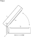
- the document transport unit 11 is fitted openably and closably (swingably) to the frame of the image reading device 1. Specifically, a rotary shaft 11a is provided on the frame on the rear side of the main body of the image reading device 1, and with the rotary shaft 11a as a pivot, the document transport unit 11 can be opened or closed. When the document transport unit 11 is closed, the document transport unit 11 overlaps the contact glass 1a, so that the contact glass 1a is completely covered by the document transport unit 11. In this way, when reading a document placed on the contact glass 1a, it is possible to hold the document under the document transport unit 11. On a part of the document transport unit 11 facing the contact glass 1a, a white pressing plate 19 is arranged to hold a document.
- the multifunction peripheral 100 is provided with a printing portion 2.
- the printing portion 2 includes a sheet feeding portion 3, a sheet transporting portion 4, an image forming portion 5, and a fixing portion 6.
- the printing portion 2 transports a sheet along a sheet transport passage 20, and while transporting it, prints an image on the sheet.
- the sheet feeding portion 3 includes a pick-up roller 31 and a sheet feeding roller pair 32, and feeds a sheet stored in a sheet cassette 21 into the sheet transport passage 20.
- the sheet transporting portion 4 includes a plurality of transport roller pairs 41, and transports a sheet along the sheet transport passage 20.
- the image forming portion 5 includes a photosensitive drum 51, a charging device 52, an exposing device 53, a developing device 54, a transfer roller 55, and a cleaning device 56.
- the image forming portion 5 forms a toner image based on image data and transfers the toner image to a sheet.
- the fixing portion 6 includes a heating roller 61 and a pressing roller 62, and fixes the toner image transferred to the sheet by applying heat and pressure thereto. Having passed through the fixing portion 6, the sheet is transported along the sheet transport passage 20 and is discharged onto a discharge tray 22.
- the multifunction peripheral 100 further includes an operation panel 3 (see Fig. 2 ).
- the operation panel 3 displays various screens and receives various settings by a user.
- the operation panel 3 includes a display panel with a touch panel.
- the operation panel 3 displays, on the display panel, software keys to receive settings (touch operations) by a user.
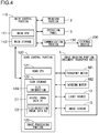
- the multifunction peripheral 100 includes a main control portion 110.
- the main control portion 110 includes a main CPU (central processing unit) 111 and a main storage 112.
- the main storage 112 stores control programs and data. Based on these control programs and data, the main control portion 110 controls the printing operation of the printing portion 2. Moreover, the main control portion 110 detects operations on the operation panel 3 and controls the display on the operation panel 3.
- the scan control portion 120 includes a scan CPU 121, a scan storage 122 (memory), and an image processing portion 123 (ASIC) (application-specific integrated circuit). This scan control portion 120 receives instructions from the main control portion 110, and controls the image reading operation of the image reading portion 1 and the document transport operation of the document transport unit 11.
- ASIC application-specific integrated circuit
- the scan control portion 120 is connected to a transport motor M1 for rotating document transport rollers (unillustrated) provided in the document transport unit 11, and rotates the document transport rollers properly. Moreover, the scan control portion 120 is connected to a winding motor M2 for rotating the winding drum 18, and rotates the winding drum 18 properly. That is, the scan control portion 120 properly moves the light source 12 in the sub-scanning direction. Furthermore, to the scan control portion 120, the light source 12 and the image sensor 13 are connected. The scan control portion 120 controls the operation of the light source 12 and of the image sensor 13.
- the image processing portion 123 in the scan control portion 120 includes an amplification circuit and an A/D conversion circuit; it amplifies the image data (the analog output from the image sensor 13) obtained through document reading and generates digital image data. Moreover, the image processing portion 123 performs image processing such as shading correction, and outputs the processed image data to the main control portion 110. For example, the main control portion 110, on receiving image data from the scan control portion 120, generates image data for exposure (data for controlling exposure by the exposing device 53) to make the printing portion 2 perform printing based on the image data.
- a communication portion 130 receives instructions from the main control portion 110 and exchanges various kinds of data such as image data with an external device 200 (a personal computer, a facsimile machine, or the like).
- an external device 200 a personal computer, a facsimile machine, or the like.
- the main control portion 110 on receiving image data from the scan control portion 120, performs necessary image processing, and transmits the image data via the communication portion 130 to the external device 200.
- the external device 200 receives the image data from the multifunction peripheral 100 and displays, for example, an image based on the image data.
- the multifunction peripheral 100 has an ID card copy mode as a mode for copying a card document D (see Fig. 5 ) such as an identification card.
- a card document D such as an identification card.
- an identification card can be a driving license, an insurance card, a cash card, a credit card, or the like.
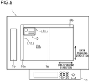
- a card document D as a reading target is placed on the contact glass 1a, and the document transport unit 11 (see Figs. 1 and 3 ) is closed. Also, when, in preparation for execution of the job in ID card copy mode, the card document D is placed on the contact glass 1a, two edges of the card document D are supposed to be aligned with the reference lines L. Then, when the operation panel 3 receives an instruction for execution of the job by a user, the main control portion 110 instructs the scan control portion 120 to make the image reading portion 1 perform reading of the card document D.
- the reading region RA including a region where the card document D is present is read by the image reading portion 1. That is, with the card document D set in the reading region RA such that two edges of the card document D are aligned with the reference lines L (L1 and L2) that extend in the main and sub scanning directions respectively, the image reading portion 1 performs reading of the reading region RA.
- the size of the reading region RA is previously determined based on the largest size of the card document D which can be a reading target.
- the image processing portion 123 When the image reading portion 1 reads the reading region RA (including the region where the card document D is present), the image processing portion 123 generates image data of the reading region RA.
- the image processing portion 123 generates, as the image data of the reading region RA, image data D1 for output and image data D2 for size detection, and stores them temporarily in the scan storage 122 (see Fig. 4 ).
- the process of generating the output image data D1 and the process of generating the size-detection image data D2 are executed concurrently.
- the output image data D1 is data that serves as a basis for the image data that is fed to the main control portion 110.
- the output image data D1 can be basic data for an image that is output to be printed on a sheet by the printing portion 2.
- the output image data D1 can be basic data for an image that is output to be displayed by the external device 200.
- the output image data D1 has a resolution of 600 dpi.
- the size-detection image data D2 is image data used for size detection of a card document D as will be described later, and is image data having a lower resolution than the output image data D1.
- the resolution of the size-detection image data D2 is one-fourth or one-eighth of the resolution of the output image data D1.
- the image processing portion 123 while generating the output image data D1, generates the size-detection image data D2 by use of an average-reduction method. For example, when the image data having a resolution of 600 dpi is reduced to one-eighth (75 dpi) by resolution conversion using an average-reduction method, the average density value of every eight pixels is taken as the density value of one pixel.
- the image processing portion 123 by use of the size-detection image data D2, performs size detection of the card document D read by the image reading portion 1 (detects the widths of the card document D in the main and sub scanning directions respectively). To perform this size detection, the image processing portion 123 checks the density value of each pixel in the size-detection image data D2, and locates the edges (those edges which are not aligned with the reference lines L) of the card document D.
- a level difference in the vicinity of the edge of the card document D casts a shadow. That is, a part of the white pressing plate 19 in the vicinity of the edge of the card document D (a part with which the card document D does not overlap) appears dark.
- the shadow cast in the vicinity of the edge of the card document D is indicated by hatching.
- the shadow cast in the vicinity of the edge of the card document D is read by the image reading portion 1.
- a high density line (a line with high density) appears, which is a line of a plurality of consecutive pixels with high density.
- the image processing portion 123 locates the edge of the card document D.
- the image processing portion 123 based on the location of the edge of the card document D (the location of the high density line), detects the size of the card document D.
- the density value gradually increases toward the reference line L1 that extends in the main scanning direction.
- the flow shown in Fig. 8 starts when the operation panel 3 receives an instruction for execution of a job in ID card copy mode.
- size detection is performed based on the location in the sub-scanning direction of the high density line that extends in the main scanning direction (one direction) out of the main and sub scanning directions.
- size detection may be performed based on the location in the main scanning direction of the high density line that extends in the sub-scanning direction.
- step S1 the scan control portion 120 makes the image reading portion 1 perform reading of the reading region RA including the region where the card document D is present. Thereafter, in step S2, the image processing portion 123 generates image data (including the image data of the card document D) of the reading region RA read by the image reading portion 1.
- the image processing portion 123 generates output image data D1 and size-detection image data D2, the latter having a lower resolution than the former.
- step S3 the image processing portion 123 performs pixel-density discrimination on each pixel in the size-detection image data D2 to check whether or not it is a high density pixel having a density value higher than that of a predetermined pixel by a predetermined value or more.
- the image processing portion 123 takes as the predetermined pixel a pixel located, with respect to a discrimination target pixel (hereinafter, also referred to as a pixel of interest), on the opposite side from the reference line L1 that extends in the main scanning direction. Specifically, the image processing portion 123, as shown in Fig. 9 , takes as the predetermined pixel P2 a pixel P located next to the pixel of interest P (P1) on the opposite side from the reference line L1.
- a pixel P located a predetermined number of pixels (a predetermined number of lines) apart from the pixel of interest P1 on the opposite side from the reference line L1 may be taken as the predetermined pixel P2.
- the density value of the shadow cast in the vicinity of the edge of the card document D gradually increases toward the reference line L1.
- the pixel P located next to the pixel of interest P1 on the opposite side from the reference line L1 be the predetermined pixel P2 (see Fig. 9 )
- the pixel of interest P1 may not be discriminated as a high density pixel (the density value of the pixel of interest P1 may not be higher than the density value of the predetermined pixel P2 by the predetermined value or more).
- the pixel P located apart from the pixel of interest P1 is preferably taken as the predetermined pixel P2. This helps reliably discriminate a pixel corresponding to a shadow as a high density pixel (helps suppress occurrence of erroneous detection).
- a pixel P located apart from the pixel of interest P1 is taken as a predetermined pixel P2
- a plurality of pixels P counted from the pixel P located next to the pixel of interest P1 on the opposite side from the reference line L1 may be taken as predetermined pixels P2.
- the image processing portion 123 calculates the average density value of the plurality of pixels P as the predetermined pixels P2. Then, the image processing portion 123 compares the density value of the pixel of interest P1 with the average density value of the predetermined pixels P2, and when the density value of the pixel of interest P1 is higher than the average density value of the predetermined pixels P2 by the predetermined value or more, the image processing portion 123 discriminates the pixel of interest P1 as a high density pixel.
- the pixel of interest P1 when only the pixel P located next to the pixel of interest P1 on the opposite side from the reference line L1 is taken as the predetermined pixel P2, then even when the pixel of interest P1 is a pixel corresponding to the shadow, if the pixel P located next to the pixel of interest P1 has increased density due to soil on the contact glass 1a or the pressing plate 19, the pixel of interest P1 may not be discriminated as a high density pixel (the density value of the pixel of interest P1 may not be higher than the density value of the predetermined pixel P2 by the predetermined value or more).
- the density value of the pixel of interest P1 is compared not only with the density value of the pixel P located next to the pixel of interest P1 but with the average density value of a plurality of pixels P including the pixel P.
- the image processing portion 123 discriminates a high density line. Specifically, the image processing portion 123 discriminates as a high density line a line of a plurality of (fewer than the pixels corresponding to the smallest width of the card document D which can be a reading target) consecutive pixels with high density in the main scanning direction. A plurality of lines, of which the number depends on the thickness of the read card document D, of pixels can be discriminated as high density lines.
- step S5 the image processing portion 123 sets as a target line (a line used for size detection) one of the plurality of lines of pixels discriminated as high density lines.
- the image processing portion 123 sets as the target line, out of the plurality of lines of pixels discriminated as high density lines, a line of pixels farthest from the reference line L1 that extends in the main scanning direction.
- the read card document D itself has a line with high density (such as a magnetic stripe).
- a line of pixels other than the line of pixels farthest from the reference line L1 for example, a line of pixels closest to the reference line L1
- the size of the card document D may be erroneously detected.
- step S6 the image processing portion 123, based on the number of pixels (the number of lines) from the reference line L1 that extends in the main scanning direction to the target line, calculates a width from the reference line L1 to the target line, and takes the width as a width for size detection (the width of one pixel multiplied by the number of lines from the reference line L1 to the target line). Then, in step S7, the image processing portion 123, based on the width for size detection, sets the size of the read card document D.
- size information 124 for setting the size of the read card document D is stored (see Fig. 4 ).
- This size information 124 is information in which a plurality of kinds of reference sizes are defined and in which the vertical and horizontal dimensions for each of the plurality of kinds of reference sizes are defined.
- the vertical and horizontal dimensions shown in the size information 124 are determined, for example, based on an international standard for identification cards (ISO/IEC 7810).
- ISO/IEC 7810 International standard for identification cards
- a size can be added to, or deleted from, those defined in the size information 124 as necessary. For example, settings relating to adding or deleting a size to or from those defined in the size information 124 are received by the operation panel 3.
- the image processing portion 123 discriminates, of the plurality of kinds of reference sizes defined in the size information 124, a predetermined reference size that has a width closest to the width for size detection (the width from the reference line L1 to the target line), and sets the discriminated predetermined reference size as the size of the card document D.
- a predetermined reference size that has a width closest to the width for size detection (the width from the reference line L1 to the target line)
- the image processing portion 123 sets the discriminated predetermined reference size as the size of the card document D.
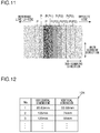
- the size information 124 shown in Fig. 12 when a width closest to the width for size detection is 85.60 mm, the size set by the image processing portion 123 is size No. 1 (85.60 mm times 53.98 mm).
- the size set by the image processing portion 123 is size No. 2 (105 mm times 74 mm).
- step S8 the image processing portion 123, based on the predetermined reference size set as the size of the card document D, performs image processing on the output image data D1, and outputs the result to the main control portion 110.
- the image processing portion 123 performs a process of extracting image data of a region corresponding to the predetermined reference size from the output image data D1.
- the image processing portion 123 then outputs the image data to the main control portion 110.
- the multifunction peripheral 100 (image reading device and image forming apparatus) according to the present embodiment includes an image reading portion 1 which shines light on a predetermined reading region RA including a region where a card document D (document) is present, and which reads the reading region RA, an image processing portion 123 which generates image data of the reading region RA read by the image reading portion 1, and which detects the size of the card document D based on the image data of the reading region RA, the image processing portion 123 performing image processing on the image data of the reading region RA based on the size of the card document D and outputting the processed image data, and a storage 122 which stores size information 124 that is information in which a plurality of kinds of reference sizes are defined and in which the vertical and horizontal dimensions for each of the plurality of kinds of reference sizes are defined.
- a card document D is set (placed on a contact glass 1a) such that two edges of the card document D are aligned with reference lines L (L1 and L2)
- the image processing portion 123 generates, as the image data of the reading region RA, image data for output D1 and image data for size detection D2, the size-detection image data D2 having a lower resolution than the output image data D1.
- the image processing portion 123 discriminates, from the size-detection image data D2, high density lines, the high density lines being lines of pixels that appear as a result of a shadow cast in the vicinity of an edge of the card document D that does not overlap the reference lines L being read, the high density lines extending in the main scanning direction.
- the image processing portion 123 performs a target line setting process to set as a target line one of a plurality of lines of pixels discriminated as the high density lines.
- the image processing portion 123 calculates as a width for size detection a width from the reference line L1 that extends in the main scanning direction to the target line.
- the image processing portion 123 sets as the size of the card document D a reference size having a width closest to the width for size detection out of the plurality of kinds of reference sizes. Then, the image processing portion 123 performs image processing on the output image data D1 based on the reference size set as the size of the card document D, and outputs the result.
- the output image data D1 and the size-detection image data D2 are generated, and out of these two sets of data, by use of the size-detection image data D2, size detection of a card document D is performed. Since the size-detection image data D2 has a lower resolution (fewer pixels) than the output image data D1, the high density lines (lines of pixels corresponding to a shadow cast in the vicinity of an edge of the card document D) can be discriminated at increased speed. As a result, size detection of a card document D can be completed speedily.
- the density values of pixels corresponding to the soil are converted to lower density values by resolution conversion using an average-reduction method. This helps suppress occurrence of erroneous detection due to soil on the contact glass 1a or the pressing plate 19.
- a target line when the target line setting process is performed, a target line may be set with consideration given to the width of a shadow cast in the vicinity of an edge of the card document D.
- shadow information that defines the width of a shadow (a shadow cast in the vicinity of an edge of the card document D) calculated based on the largest thickness of the card document D which can be a reading target is previously stored in the scan storage 122.
- a shadow is cast in the vicinity of an edge of the card document D due to the card document D having a thickness (the thicker the card document D is, the larger the width of the shadow is).
- the width of the shadow can be calculated based on the thickness.
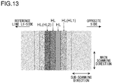
- the image processing portion 123 discriminates, out of a plurality of lines of pixels HL discriminated as the high density lines, a line of pixels HL1 farthest from the reference line L1 that extends in the main scanning direction. Then, the image processing portion 123 sets as the target line a line of pixels HL2 located at a position advanced toward the reference line L1 over the number of lines (the number of pixels) counted from the line of pixels HL1 corresponding to the width of the shadow defined in the shadow information.
- the deviation of a width for size detection (a width from the reference line L1 to a target line) from the actual width of a card document D is reduced.
- the outermost pixel of a region with increased density is detected, and thus the size of a card document D that is actually detected tends to be larger than it actually is by the width of a shadow.
- the width of the shadow it is possible to obtain a more accurate size. That is, by previously calculating the width of a shadow for a given thickness or size, and performing correction as by subtracting it from the detected size of a card document D, it is possible to obtain a more accurate size.
- each pixel in the size-detection image data may be checked against the density value of the white pressing plate 19 to discriminate whether or not the pixel is a high density pixel.
- the density value of the pressing plate 19 calculated based on the image data obtained by reading the pressing plate 19 is previously stored in the scan storage 122.
- the image processing portion 123 discriminates, for each pixel in the size-detection image data, whether or not the pixel is a high density pixel having a higher density value than the pressing plate 19 by the predetermined value or more. Moreover, the image processing portion 123 discriminates high density lines that are lines of a plurality of consecutive pixels with high density in the main scanning direction. After this discrimination, the image processing portion 123 sets as the target line, out of the plurality of lines of pixels discriminated as the high density lines, a line of pixels farthest from the reference line L1 that extends in the main scanning direction.
Landscapes
- Engineering & Computer Science (AREA)
- Multimedia (AREA)
- Signal Processing (AREA)
- Facsimile Scanning Arrangements (AREA)
- Image Input (AREA)
- Editing Of Facsimile Originals (AREA)
Abstract
Description
- The present disclosure relates to an image reading device and an image forming apparatus.
- In a conventional image reading device, in preparation for document reading, by a user, a document as a reading target is placed on a document stage, and the document placed on the document stage is held by a document cover. Then, when reading the document placed on the document stage, the image reading device radiates light toward the document stage, focuses the light reflected from the document and from the document cover on an image sensor, and generates image data based on an analog signal output from the image sensor.
- The image data (read image data) generated as described above includes image data of the document and image data of the document cover. Thus, to extract only the image data of the document from the read image data, size detection of the document (document edge detection) is often performed based on the read image data. For example, in one conventional configuration, an edge of a document is detected by discriminating, from the read image data, black lines (lines of pixels corresponding to a shadow) that appear as a result of a shadow cast in the vicinity of an edge of the document being read.
- According to a first aspect of the present disclosure, an image reading device includes an image reading portion, an image processing portion, and a storage. The image reading portion shines light on a predetermined reading region including a region where a document is present, and reads the reading region. The image processing portion generates image data of the reading region read by the image reading portion, detects the size of the document based on the image data of the reading region, performs image processing on the image data of the reading region based on the size of the document, and outputs the processed image data. The storage stores size information that is information in which the vertical and horizontal dimensions for each of a plurality of kinds of reference sizes are defined. The image reading portion performs reading of the reading region with the document set in the reading region such that two edges of the document are aligned with reference lines that extend in the main and sub scanning directions. The image processing portion generates, as the image data of the reading region, image data for output and image data for size detection, the image data for size detection having a lower resolution than the output image data. The image processing portion discriminates, from the image data for size detection, high density lines, the high density lines being lines of pixels that appear as a result of a shadow cast in the vicinity of an edge of the document that does not overlap the reference lines being read, the high density lines extending in one direction out of the main and sub scanning directions. The image processing portion performs a target line setting process to set one of the high density lines as a target line. The image processing portion calculates as a width for size detection a width from, out of the reference lines that extend in the main and sub scanning directions, a reference line that extends in the one direction out of the main and sub scanning directions to the target line. The image processing portion sets as the size of the document a reference size having a width closest to the width for size detection out of the plurality of kinds of the reference sizes. The image processing portion performs image processing on the image data for output based on the reference size set as the size of the document, and outputs the processed image data.
- According to a second aspect of the present disclosure, an image forming apparatus includes the image reading device described above.
-
-
Fig. 1 is a schematic diagram of a multifunction peripheral according to one embodiment of the present disclosure; -
Fig. 2 is a plan view of an image reading portion (with a document transport unit omitted from illustration) of a multifunction peripheral according to one embodiment of the present disclosure; -
Fig. 3 is a side view of an image reading portion (with a document transport unit open) of a multifunction peripheral according to one embodiment of the present disclosure; -
Fig. 4 is a block diagram showing a hardware configuration of a multifunction peripheral according to one embodiment of the present disclosure; -
Fig. 5 is a diagram illustrating a card document set on a multifunction peripheral according to one embodiment of the present disclosure; -
Fig. 6 is a diagram illustrating a shadow cast when a card document is read by a multifunction peripheral according to one embodiment of the present disclosure; -
Fig. 7 is an enlarged diagram of a part (part corresponding to the vicinity of an edge of a card document) of image data of a card document generated by a multifunction peripheral according to one embodiment of the present disclosure; -
Fig. 8 is a flow chart illustrating the flow of a process of detecting the size of a card document by a multifunction peripheral according to one embodiment of the present disclosure; -
Fig. 9 is a diagram illustrating a target line setting process (discrimination of high density pixels) performed when the size of a card document is detected by a multifunction peripheral according to one embodiment of the present disclosure; -
Fig. 10 is a diagram illustrating a target line setting process (discrimination of high density pixels) performed when the size of a card document is detected by a multifunction peripheral according to one embodiment of the present disclosure; -
Fig. 11 is a diagram illustrating a target line setting process (discrimination of high density pixels) performed when the size of a card document is detected by a multifunction peripheral according to one embodiment of the present disclosure; -
Fig. 12 is a diagram illustrating size information referred to when the size of a card document is detected by a multifunction peripheral according to one embodiment of the present disclosure; and -
Fig. 13 is a diagram illustrating a target line setting process performed when the size of a card document is detected by a multifunction peripheral according to one embodiment of the present disclosure. - Hereinafter, a description will be given of an image reading device and an image forming apparatus according to the present disclosure. The following description deals with, as an example, a multifunction peripheral having the functions of a copier, a printer, etc.
- OVERALL CONSTRUCTION OF MULTIFUNCTION PERIPHERAL: As shown in
Fig. 1 , in this embodiment, the multifunction peripheral 100 is provided with animage reading portion 1 including adocument transport unit 11. Here, the multifunction peripheral 100 corresponds to an "image reading device" and an "image forming apparatus". - The
image reading portion 1 has a frame having, fitted in it, a contact glass la for placement reading and acontact glass 1b for transport reading. Theimage reading portion 1 performs placement reading to read a document placed on thecontact glass 1a and performs transport reading to read a document D passing across thecontact glass 1b. In transport reading, a document is transported across thecontact glass 1b by thedocument transport unit 11. - The
image reading portion 1 includes alight source 12, animage sensor 13, amirror 14, and alens 15, and reads a document optically. These components that constitute theimage reading portion 1 are arranged inside the frame of theimage reading portion 1. - The
light source 12 comprises a plurality of LED (light-emitting diode) elements and generates light with which a document is irradiated. The plurality of LED elements are arranged in a row extending in the main scanning direction. In placement reading, thelight source 12 radiates light toward thecontact glass 1a (the light that has been transmitted through thecontact glass 1a illuminates the document). On the other hand, in transport reading, thelight source 12 radiates light toward thecontact glass 1b (the light that has been transmitted through thecontact glass 1b illuminates the document). The light reflected from the document is then reflected on themirror 14 so as to be guided into thelens 15. Thelens 15 converges the reflected light. - The
image sensor 13 reads a document line-by-line by receiving the light reflected from the document (the light converged through the lens 15). Thisimage sensor 13 comprises a CCD (charge coupled device) having a plurality of photoelectric conversion elements arranged in a row extending in the main scanning direction. Theimage sensor 13, on receiving the reflected light, performs photoelectric conversion and stores electric charge for each pixel, line-by-line. Then, theimage sensor 13 outputs an analog signal according to the stored electric charge. That is, the analog output from theimage sensor 13 varies from one pixel to another according to the amount of reflected light. - The
light source 12 and themirror 14 are fitted to amovable frame 16 which is movable in the sub-scanning direction orthogonal to the main scanning direction. Themovable frame 16 is coupled to one end of awire 17. The other end of thiswire 17 is coupled to a windingdrum 18. Thus, as thewinding drum 18 rotates, themovable frame 16 moves in the sub-scanning direction. That is, thelight source 12 moves (the reading position moves) in the sub-scanning direction. - In placement reading, the
light source 12 moves in a direction from left to right as seen from the front of the apparatus. Thelight source 12, while moving in the sub-scanning direction, irradiates a document placed on thecontact glass 1a with light. Here, theimage sensor 13 continuously and repeatedly performs photoelectric conversion on the light reflected from the document. Thus, document reading is performed line-by-line. In transport reading, thelight source 12 remains at rest under thecontact glass 1b and irradiates a document passing across thecontact glass 1b with light. - Here, as shown in
Fig. 2 , when, in preparation for placement reading on the multifunction peripheral 100, a document is placed on thecontact glass 1a, the size of the document is supposed to be detected, with two edges of the document aligned with reference lines L (L1 and L2) that extend in the main and sub scanning directions respectively. That is, on thecontact glass 1a, the reference lines L are provided. To place a document on thecontact glass 1a in a state aligned with the reference lines L, on thecontact glass 1a, document scales 10a and 10b which function as document positioning members (members which indicate the placement position of a document) on thecontact glass 1a are arranged. Thedocument scale 10a is arranged so as to extend in the main scanning direction to determine the placement position of a document in the sub-scanning direction. Thedocument scale 10b is arranged so as to extend in the sub-scanning direction to determine the placement position of a document in the main scanning direction. - As shown in
Fig. 3 , thedocument transport unit 11 is fitted openably and closably (swingably) to the frame of theimage reading device 1. Specifically, arotary shaft 11a is provided on the frame on the rear side of the main body of theimage reading device 1, and with therotary shaft 11a as a pivot, thedocument transport unit 11 can be opened or closed. When thedocument transport unit 11 is closed, thedocument transport unit 11 overlaps thecontact glass 1a, so that thecontact glass 1a is completely covered by thedocument transport unit 11. In this way, when reading a document placed on thecontact glass 1a, it is possible to hold the document under thedocument transport unit 11. On a part of thedocument transport unit 11 facing thecontact glass 1a, a whitepressing plate 19 is arranged to hold a document. - Back in
Fig. 1 , the multifunction peripheral 100 is provided with aprinting portion 2. Theprinting portion 2 includes asheet feeding portion 3, asheet transporting portion 4, animage forming portion 5, and a fixingportion 6. Theprinting portion 2 transports a sheet along asheet transport passage 20, and while transporting it, prints an image on the sheet. - The
sheet feeding portion 3 includes a pick-uproller 31 and a sheet feedingroller pair 32, and feeds a sheet stored in asheet cassette 21 into thesheet transport passage 20. Thesheet transporting portion 4 includes a plurality of transport roller pairs 41, and transports a sheet along thesheet transport passage 20. - The
image forming portion 5 includes aphotosensitive drum 51, a chargingdevice 52, an exposingdevice 53, a developingdevice 54, atransfer roller 55, and acleaning device 56. Theimage forming portion 5 forms a toner image based on image data and transfers the toner image to a sheet. The fixingportion 6 includes aheating roller 61 and apressing roller 62, and fixes the toner image transferred to the sheet by applying heat and pressure thereto. Having passed through the fixingportion 6, the sheet is transported along thesheet transport passage 20 and is discharged onto adischarge tray 22. - The multifunction peripheral 100 further includes an operation panel 3 (see
Fig. 2 ). Theoperation panel 3 displays various screens and receives various settings by a user. For example, theoperation panel 3 includes a display panel with a touch panel. Theoperation panel 3 displays, on the display panel, software keys to receive settings (touch operations) by a user. - HARDWARE CONFIGURATION OF MULTIFUNCTION PERIPHERAL: As shown in
Fig. 4 , the multifunction peripheral 100 includes amain control portion 110. Themain control portion 110 includes a main CPU (central processing unit) 111 and amain storage 112. Themain storage 112 stores control programs and data. Based on these control programs and data, themain control portion 110 controls the printing operation of theprinting portion 2. Moreover, themain control portion 110 detects operations on theoperation panel 3 and controls the display on theoperation panel 3. - To the
main control portion 110, ascan control portion 120 is connected. Thescan control portion 120 includes ascan CPU 121, a scan storage 122 (memory), and an image processing portion 123 (ASIC) (application-specific integrated circuit). Thisscan control portion 120 receives instructions from themain control portion 110, and controls the image reading operation of theimage reading portion 1 and the document transport operation of thedocument transport unit 11. - Specifically, the
scan control portion 120 is connected to a transport motor M1 for rotating document transport rollers (unillustrated) provided in thedocument transport unit 11, and rotates the document transport rollers properly. Moreover, thescan control portion 120 is connected to a winding motor M2 for rotating the windingdrum 18, and rotates the windingdrum 18 properly. That is, thescan control portion 120 properly moves thelight source 12 in the sub-scanning direction. Furthermore, to thescan control portion 120, thelight source 12 and theimage sensor 13 are connected. Thescan control portion 120 controls the operation of thelight source 12 and of theimage sensor 13. - The
image processing portion 123 in thescan control portion 120 includes an amplification circuit and an A/D conversion circuit; it amplifies the image data (the analog output from the image sensor 13) obtained through document reading and generates digital image data. Moreover, theimage processing portion 123 performs image processing such as shading correction, and outputs the processed image data to themain control portion 110. For example, themain control portion 110, on receiving image data from thescan control portion 120, generates image data for exposure (data for controlling exposure by the exposing device 53) to make theprinting portion 2 perform printing based on the image data. - Moreover, to the
main control portion 110, acommunication portion 130 is connected. Thecommunication portion 130 receives instructions from themain control portion 110 and exchanges various kinds of data such as image data with an external device 200 (a personal computer, a facsimile machine, or the like). For example, themain control portion 110, on receiving image data from thescan control portion 120, performs necessary image processing, and transmits the image data via thecommunication portion 130 to theexternal device 200. Theexternal device 200 receives the image data from the multifunction peripheral 100 and displays, for example, an image based on the image data. - SIZE DETECTION OF CARD DOCUMENT: The multifunction peripheral 100 has an ID card copy mode as a mode for copying a card document D (see
Fig. 5 ) such as an identification card. For example, in ID card copy mode, instructions for execution of jobs are received by theoperation panel 3. Here, an identification card can be a driving license, an insurance card, a cash card, a credit card, or the like. - In preparation for execution of a job in ID card copy mode, as shown in
Fig. 5 , first, by a user, a card document D as a reading target is placed on thecontact glass 1a, and the document transport unit 11 (seeFigs. 1 and3 ) is closed. Also, when, in preparation for execution of the job in ID card copy mode, the card document D is placed on thecontact glass 1a, two edges of the card document D are supposed to be aligned with the reference lines L. Then, when theoperation panel 3 receives an instruction for execution of the job by a user, themain control portion 110 instructs thescan control portion 120 to make theimage reading portion 1 perform reading of the card document D. - For example, in ID card copy mode, within the surface of the
contact glass 1a, a region closer to the reference line L1 with respect to the broken-line inFig. 5 is taken as a reading region RA. Thus, the reading region RA including a region where the card document D is present is read by theimage reading portion 1. That is, with the card document D set in the reading region RA such that two edges of the card document D are aligned with the reference lines L (L1 and L2) that extend in the main and sub scanning directions respectively, theimage reading portion 1 performs reading of the reading region RA. The size of the reading region RA is previously determined based on the largest size of the card document D which can be a reading target. - When the
image reading portion 1 reads the reading region RA (including the region where the card document D is present), theimage processing portion 123 generates image data of the reading region RA. Here, theimage processing portion 123 generates, as the image data of the reading region RA, image data D1 for output and image data D2 for size detection, and stores them temporarily in the scan storage 122 (seeFig. 4 ). The process of generating the output image data D1 and the process of generating the size-detection image data D2 are executed concurrently. - The output image data D1 is data that serves as a basis for the image data that is fed to the
main control portion 110. In other words, the output image data D1 can be basic data for an image that is output to be printed on a sheet by theprinting portion 2. Or, the output image data D1 can be basic data for an image that is output to be displayed by theexternal device 200. For example, the output image data D1 has a resolution of 600 dpi. - The size-detection image data D2 is image data used for size detection of a card document D as will be described later, and is image data having a lower resolution than the output image data D1. The resolution of the size-detection image data D2 is one-fourth or one-eighth of the resolution of the output image data D1. The
image processing portion 123, while generating the output image data D1, generates the size-detection image data D2 by use of an average-reduction method. For example, when the image data having a resolution of 600 dpi is reduced to one-eighth (75 dpi) by resolution conversion using an average-reduction method, the average density value of every eight pixels is taken as the density value of one pixel. - Thereafter, the
image processing portion 123, by use of the size-detection image data D2, performs size detection of the card document D read by the image reading portion 1 (detects the widths of the card document D in the main and sub scanning directions respectively). To perform this size detection, theimage processing portion 123 checks the density value of each pixel in the size-detection image data D2, and locates the edges (those edges which are not aligned with the reference lines L) of the card document D. - Here, due to the card document D having a thickness, when, while the card document D is read, light is shone in the vicinity of an edge of the card document D, as shown in
Fig. 6 , a level difference in the vicinity of the edge of the card document D casts a shadow. That is, a part of the whitepressing plate 19 in the vicinity of the edge of the card document D (a part with which the card document D does not overlap) appears dark. InFig. 6 , the shadow cast in the vicinity of the edge of the card document D is indicated by hatching. - The shadow cast in the vicinity of the edge of the card document D is read by the
image reading portion 1. As a result, in a part of the image data of the reading region RA corresponding to the vicinity of the edge of the card document D, a high density line (a line with high density) appears, which is a line of a plurality of consecutive pixels with high density. By discriminating this high density line, theimage processing portion 123 locates the edge of the card document D. Then, theimage processing portion 123, based on the location of the edge of the card document D (the location of the high density line), detects the size of the card document D. As shown inFig. 7 , in the vicinity of an edge of the card document D, the density value gradually increases toward the reference line L1 that extends in the main scanning direction. - Next, with reference to the flow chart shown in
Fig. 8 , the flow of the process of detecting the size of the card document D will be described. The flow shown inFig. 8 starts when theoperation panel 3 receives an instruction for execution of a job in ID card copy mode. - The following description deals with, as an example, a case where size detection is performed based on the location in the sub-scanning direction of the high density line that extends in the main scanning direction (one direction) out of the main and sub scanning directions. Instead, size detection may be performed based on the location in the main scanning direction of the high density line that extends in the sub-scanning direction.
- In step S1, the
scan control portion 120 makes theimage reading portion 1 perform reading of the reading region RA including the region where the card document D is present. Thereafter, in step S2, theimage processing portion 123 generates image data (including the image data of the card document D) of the reading region RA read by theimage reading portion 1. Here, theimage processing portion 123 generates output image data D1 and size-detection image data D2, the latter having a lower resolution than the former. - Then, in step S3, the
image processing portion 123 performs pixel-density discrimination on each pixel in the size-detection image data D2 to check whether or not it is a high density pixel having a density value higher than that of a predetermined pixel by a predetermined value or more. - When performing pixel-density discrimination, the
image processing portion 123 takes as the predetermined pixel a pixel located, with respect to a discrimination target pixel (hereinafter, also referred to as a pixel of interest), on the opposite side from the reference line L1 that extends in the main scanning direction. Specifically, theimage processing portion 123, as shown inFig. 9 , takes as the predetermined pixel P2 a pixel P located next to the pixel of interest P (P1) on the opposite side from the reference line L1. - As another example, as shown in
Fig. 10 , a pixel P located a predetermined number of pixels (a predetermined number of lines) apart from the pixel of interest P1 on the opposite side from the reference line L1 may be taken as the predetermined pixel P2. - Here, the density value of the shadow cast in the vicinity of the edge of the card document D gradually increases toward the reference line L1. Thus, let the pixel P located next to the pixel of interest P1 on the opposite side from the reference line L1 be the predetermined pixel P2 (see
Fig. 9 ), then even when the pixel of interest P1 is a pixel corresponding to the shadow, the pixel of interest P1 may not be discriminated as a high density pixel (the density value of the pixel of interest P1 may not be higher than the density value of the predetermined pixel P2 by the predetermined value or more). Thus, the pixel P located apart from the pixel of interest P1 is preferably taken as the predetermined pixel P2. This helps reliably discriminate a pixel corresponding to a shadow as a high density pixel (helps suppress occurrence of erroneous detection). - In a case where a pixel P located apart from the pixel of interest P1 is taken as a predetermined pixel P2, although no particular limitation is meant, for example, it is preferable to take as the predetermined pixel P2 a pixel P as many pixels apart from the pixel of interest P1 as the number of pixels corresponding to the width of the shadow (the shadow cast in the vicinity of the edge of the card document D) calculated based on the largest thickness of the card document D which can be a reading target. With this configuration, it is possible to more reliably discriminate a pixel corresponding to a shadow as a high density pixel.
- As yet another example, as shown in
Fig. 11 , a plurality of pixels P counted from the pixel P located next to the pixel of interest P1 on the opposite side from the reference line L1 may be taken as predetermined pixels P2. In this case, theimage processing portion 123 calculates the average density value of the plurality of pixels P as the predetermined pixels P2. Then, theimage processing portion 123 compares the density value of the pixel of interest P1 with the average density value of the predetermined pixels P2, and when the density value of the pixel of interest P1 is higher than the average density value of the predetermined pixels P2 by the predetermined value or more, theimage processing portion 123 discriminates the pixel of interest P1 as a high density pixel. - Here, when only the pixel P located next to the pixel of interest P1 on the opposite side from the reference line L1 is taken as the predetermined pixel P2, then even when the pixel of interest P1 is a pixel corresponding to the shadow, if the pixel P located next to the pixel of interest P1 has increased density due to soil on the
contact glass 1a or thepressing plate 19, the pixel of interest P1 may not be discriminated as a high density pixel (the density value of the pixel of interest P1 may not be higher than the density value of the predetermined pixel P2 by the predetermined value or more). Thus, preferably, the density value of the pixel of interest P1 is compared not only with the density value of the pixel P located next to the pixel of interest P1 but with the average density value of a plurality of pixels P including the pixel P. With this configuration, it is possible to more reliably discriminate a pixel corresponding to a shadow as a high density pixel. - Back in
Fig. 8 , after discriminating a high density pixel, in step S4, theimage processing portion 123 discriminates a high density line. Specifically, theimage processing portion 123 discriminates as a high density line a line of a plurality of (fewer than the pixels corresponding to the smallest width of the card document D which can be a reading target) consecutive pixels with high density in the main scanning direction. A plurality of lines, of which the number depends on the thickness of the read card document D, of pixels can be discriminated as high density lines. - Then, in step S5, the
image processing portion 123 sets as a target line (a line used for size detection) one of the plurality of lines of pixels discriminated as high density lines. For example, theimage processing portion 123 sets as the target line, out of the plurality of lines of pixels discriminated as high density lines, a line of pixels farthest from the reference line L1 that extends in the main scanning direction. - In some cases, the read card document D itself has a line with high density (such as a magnetic stripe). In this case, when, out of the plurality of lines of pixels as high density lines, a line of pixels other than the line of pixels farthest from the reference line L1 (for example, a line of pixels closest to the reference line L1) is set as the target line, the size of the card document D may be erroneously detected. Thus, it is preferable to take as the target line a line of pixels farthest from the reference line L1 out of a plurality of lines of pixels as high density lines.
- Then, in step S6, the
image processing portion 123, based on the number of pixels (the number of lines) from the reference line L1 that extends in the main scanning direction to the target line, calculates a width from the reference line L1 to the target line, and takes the width as a width for size detection (the width of one pixel multiplied by the number of lines from the reference line L1 to the target line). Then, in step S7, theimage processing portion 123, based on the width for size detection, sets the size of the read card document D. - For example, in the
scan storage 122,size information 124 for setting the size of the read card document D is stored (seeFig. 4 ). Thissize information 124 is information in which a plurality of kinds of reference sizes are defined and in which the vertical and horizontal dimensions for each of the plurality of kinds of reference sizes are defined. The vertical and horizontal dimensions shown in thesize information 124 are determined, for example, based on an international standard for identification cards (ISO/IEC 7810). One example of thesize information 124 is shown inFig. 12 . - A size can be added to, or deleted from, those defined in the
size information 124 as necessary. For example, settings relating to adding or deleting a size to or from those defined in thesize information 124 are received by theoperation panel 3. - Then, the
image processing portion 123 discriminates, of the plurality of kinds of reference sizes defined in thesize information 124, a predetermined reference size that has a width closest to the width for size detection (the width from the reference line L1 to the target line), and sets the discriminated predetermined reference size as the size of the card document D. For example, with thesize information 124 shown inFig. 12 , when a width closest to the width for size detection is 85.60 mm, the size set by theimage processing portion 123 is size No. 1 (85.60 mm times 53.98 mm). For another example, when a width closest to the width for size detection is 74 mm, the size set by theimage processing portion 123 is size No. 2 (105 mm times 74 mm). - Then, in step S8, the
image processing portion 123, based on the predetermined reference size set as the size of the card document D, performs image processing on the output image data D1, and outputs the result to themain control portion 110. For example, theimage processing portion 123 performs a process of extracting image data of a region corresponding to the predetermined reference size from the output image data D1. Theimage processing portion 123 then outputs the image data to themain control portion 110. - As described above, the multifunction peripheral 100 (image reading device and image forming apparatus) according to the present embodiment includes an
image reading portion 1 which shines light on a predetermined reading region RA including a region where a card document D (document) is present, and which reads the reading region RA, animage processing portion 123 which generates image data of the reading region RA read by theimage reading portion 1, and which detects the size of the card document D based on the image data of the reading region RA, theimage processing portion 123 performing image processing on the image data of the reading region RA based on the size of the card document D and outputting the processed image data, and astorage 122 which stores sizeinformation 124 that is information in which a plurality of kinds of reference sizes are defined and in which the vertical and horizontal dimensions for each of the plurality of kinds of reference sizes are defined. In preparation for reading by theimage reading portion 1, a card document D is set (placed on acontact glass 1a) such that two edges of the card document D are aligned with reference lines L (L1 and L2) that extend in the main and sub scanning directions respectively. - In this configuration, the
image processing portion 123 generates, as the image data of the reading region RA, image data for output D1 and image data for size detection D2, the size-detection image data D2 having a lower resolution than the output image data D1. Theimage processing portion 123 discriminates, from the size-detection image data D2, high density lines, the high density lines being lines of pixels that appear as a result of a shadow cast in the vicinity of an edge of the card document D that does not overlap the reference lines L being read, the high density lines extending in the main scanning direction. Theimage processing portion 123 performs a target line setting process to set as a target line one of a plurality of lines of pixels discriminated as the high density lines. Theimage processing portion 123 calculates as a width for size detection a width from the reference line L1 that extends in the main scanning direction to the target line. Theimage processing portion 123 sets as the size of the card document D a reference size having a width closest to the width for size detection out of the plurality of kinds of reference sizes. Then, theimage processing portion 123 performs image processing on the output image data D1 based on the reference size set as the size of the card document D, and outputs the result. - In this embodiment, the output image data D1 and the size-detection image data D2 are generated, and out of these two sets of data, by use of the size-detection image data D2, size detection of a card document D is performed. Since the size-detection image data D2 has a lower resolution (fewer pixels) than the output image data D1, the high density lines (lines of pixels corresponding to a shadow cast in the vicinity of an edge of the card document D) can be discriminated at increased speed. As a result, size detection of a card document D can be completed speedily.
- Moreover, even if the
contact glass 1a or apressing plate 19 is soiled, the density values of pixels corresponding to the soil are converted to lower density values by resolution conversion using an average-reduction method. This helps suppress occurrence of erroneous detection due to soil on thecontact glass 1a or thepressing plate 19. - Incidentally, when the target line setting process is performed, a target line may be set with consideration given to the width of a shadow cast in the vicinity of an edge of the card document D. In this configuration, shadow information that defines the width of a shadow (a shadow cast in the vicinity of an edge of the card document D) calculated based on the largest thickness of the card document D which can be a reading target is previously stored in the
scan storage 122. As shown inFig. 6 , a shadow is cast in the vicinity of an edge of the card document D due to the card document D having a thickness (the thicker the card document D is, the larger the width of the shadow is). Thus, when the thickness of a card document D is known, the width of the shadow can be calculated based on the thickness. - Now, as shown in
Fig. 13 , when performing the target line setting process, theimage processing portion 123 discriminates, out of a plurality of lines of pixels HL discriminated as the high density lines, a line of pixels HL1 farthest from the reference line L1 that extends in the main scanning direction. Then, theimage processing portion 123 sets as the target line a line of pixels HL2 located at a position advanced toward the reference line L1 over the number of lines (the number of pixels) counted from the line of pixels HL1 corresponding to the width of the shadow defined in the shadow information. - With this configuration, the deviation of a width for size detection (a width from the reference line L1 to a target line) from the actual width of a card document D is reduced. This helps accurately perform size detection of a card document D. In the shadow detection algorithm, the outermost pixel of a region with increased density is detected, and thus the size of a card document D that is actually detected tends to be larger than it actually is by the width of a shadow. Thus, by subtracting the width of the shadow from the detected size, it is possible to obtain a more accurate size. That is, by previously calculating the width of a shadow for a given thickness or size, and performing correction as by subtracting it from the detected size of a card document D, it is possible to obtain a more accurate size.
- Moreover, when the target line setting process is performed, each pixel in the size-detection image data may be checked against the density value of the white
pressing plate 19 to discriminate whether or not the pixel is a high density pixel. In this configuration, the density value of thepressing plate 19 calculated based on the image data obtained by reading thepressing plate 19 is previously stored in thescan storage 122. - Then, when performing the target line setting process, the
image processing portion 123 discriminates, for each pixel in the size-detection image data, whether or not the pixel is a high density pixel having a higher density value than thepressing plate 19 by the predetermined value or more. Moreover, theimage processing portion 123 discriminates high density lines that are lines of a plurality of consecutive pixels with high density in the main scanning direction. After this discrimination, theimage processing portion 123 sets as the target line, out of the plurality of lines of pixels discriminated as the high density lines, a line of pixels farthest from the reference line L1 that extends in the main scanning direction. - It should be understood that the embodiments disclosed herein are illustrative in all respects and are not restrictive. The scope of the present disclosure is defined not by the description of embodiments given above but by the appended claims, and encompasses many modifications and variations made in the sense and scope equivalent to those of the claims. The above embodiments of the invention as well as the appended claims and figures show multiple characterizing features of the invention in specific combinations. The skilled person will easily be able to consider further combinations or sub-combinations of these features in order to adapt the invention as defined in the claims to his specific needs.
Claims (10)
- An image reading device (100) comprising:an image reading portion (1) which shines light on a predetermined reading region (RA) including a region where a document (D) is present, and which reads the reading region (RA);an image processing portion (123) which generates image data of the reading region (RA) read by the image reading portion (1), and which detects a size of the document (D) based on the image data of the reading region (RA), the image processing portion (123) performing image processing on the image data of the reading region (RA) based on the size of the document (D) and outputting the processed image data; anda storage (122) which stores size information (124) that is information in which vertical and horizontal dimensions for each of a plurality of kinds of reference sizes are defined,whereinthe image reading portion (1) performs reading of the reading region (RA) with the document (D) set in the reading region (RA) such that two edges of the document (D) are aligned with reference lines (L) that extend in main and sub scanning directions,the image processing portion (123) generates, as the image data of the reading region (RA), image data for output (D1) and image data for size detection (D2), the image data for size detection (D2) having a lower resolution than the image data for output (D1),the image processing portion (123) discriminates, from the image data for size detection (D2), high density lines, the high density lines being lines of pixels that appear as a result of a shadow cast in a vicinity of an edge of the document (D) that does not overlap the reference lines (L) being read, the high density lines extending in one direction out of the main and sub scanning directions,the image processing portion (123) performs a target line setting process to set one of the high density lines as a target line,the image processing portion (123) calculates as a width for size detection a width from, out of the reference lines that extend in the main and sub scanning directions, a reference line (L) that extends in the one direction out of the main and sub scanning directions to the target line,the image processing portion (123) sets as the size of the document (D) a reference size having a width closest to the width for size detection out of the plurality of kinds of the reference sizes, andthe image processing portion (123) performs image processing on the image data for output (D1) based on the reference size set as the size of the document (D), and outputs the image data.
- The image reading device (100) of claim 1, wherein
when performing the target line setting process, the image processing portion (123) performs pixel-density discrimination on each pixel in the image data for size detection (D2) to check whether or not the pixel is a high density pixel having a higher density value than a predetermined pixel by a predetermined value or more, discriminates, as the high density lines, lines of consecutive pixels with high density in the one direction, and sets as the target line, out of a plurality of lines of pixels discriminated as the high density lines, a line of pixels farthest from the reference line (L) that extends in the one direction, and
when performing the pixel-density discrimination, the image processing portion (123) takes as the predetermined pixel a pixel located on an opposite side of a discrimination target pixel from the reference line (L) that extends in the one direction. - The image reading device (100) of claim 2, wherein
the image processing portion (123) takes as the predetermined pixel a pixel located next to the discrimination target pixel on the opposite side thereof from the reference line (L) that extends in the one direction. - The image reading device (100) of claim 2, wherein
the image processing portion (123) takes as the predetermined pixel a pixel located a predetermined number of pixels apart from the discrimination target pixel on the opposite side thereof from the reference line (L) that extends in the one direction. - The image reading device (100) of claim 4, wherein
the predetermined number of pixels is set equal to or larger than a number of pixels corresponding to a width of the shadow calculated based on a largest thickness of a document which can be a reading target. - The image reading device (100) of claim 2, wherein
the image processing portion (123) takes as the predetermined pixel a plurality of pixels counted from a pixel located next to the discrimination target pixel on the opposite side thereof from the reference line (L) that extends in the one direction, and discriminates as the high density pixel a pixel of which a density value is higher than an average density value of the plurality of pixels as the predetermined pixel by the predetermined value or more. - The image reading device (100) of claim 1, wherein
the storage (122) stores a width of the shadow calculated based on a largest thickness of a document which can be a reading target, and
when performing the target line setting process, the image processing portion (123) discriminates, out of a plurality of lines of pixels discriminated as the high density lines, a line of pixels farthest from the reference line (L) that extends in the one direction, and sets as the target line a line of pixels located at a position advanced, over a number of lines counted from the discriminated line of pixels corresponding to the width of the shadow, toward the reference line (L) that extends in the one direction. - The image reading device (100) of claim 1, wherein
the image reading portion (1) includes a white pressing plate (19) for holding the document (D) when reading the document (D),
the storage (122) stores a density value of the pressing plate (19) calculated based on image data obtained by reading the pressing plate (19), and
when performing the target line setting process, the image processing portion (123) discriminates, for each pixel in the image data for size detection (D2), whether or not the pixel is a high density pixel having a higher density value than the pressing plate (19) by a predetermined value or more, discriminates, as the high density lines, lines of consecutive pixels with high density in the one direction, and sets as the target line, out of a plurality of lines of pixels discriminated as the high density lines, a line of pixels farthest from the reference line (L) that extends in the one direction. - The image reading device (100) of any one of claims 1 to 8, wherein
the document (D) is a card document (D). - An image forming apparatus (100) comprising the image reading device (100) of any one of claims 1 to 8.
Applications Claiming Priority (1)
| Application Number | Priority Date | Filing Date | Title |
|---|---|---|---|
| JP2015085110A JP6311641B2 (en) | 2015-04-17 | 2015-04-17 | Image reading apparatus and image forming apparatus |
Publications (1)
| Publication Number | Publication Date |
|---|---|
| EP3082329A1 true EP3082329A1 (en) | 2016-10-19 |
Family
ID=55750348
Family Applications (1)
| Application Number | Title | Priority Date | Filing Date |
|---|---|---|---|
| EP16164875.3A Ceased EP3082329A1 (en) | 2015-04-17 | 2016-04-12 | Image reading device and image forming apparatus with original size detection taking into account a shadow cast by an original. |
Country Status (4)
| Country | Link |
|---|---|
| US (1) | US9641712B2 (en) |
| EP (1) | EP3082329A1 (en) |
| JP (1) | JP6311641B2 (en) |
| CN (1) | CN106060306B (en) |
Families Citing this family (6)
| Publication number | Priority date | Publication date | Assignee | Title |
|---|---|---|---|---|
| US10834281B2 (en) * | 2017-05-26 | 2020-11-10 | Fuji Xerox Co., Ltd. | Document size detecting by matching between image of entire document and read size image |
| JP2019033413A (en) * | 2017-08-09 | 2019-02-28 | 株式会社リコー | Reading apparatus and image forming apparatus |
| JP6733629B2 (en) * | 2017-09-06 | 2020-08-05 | 京セラドキュメントソリューションズ株式会社 | Image reading device and image processing device |
| JP6870649B2 (en) * | 2018-04-23 | 2021-05-12 | 京セラドキュメントソリューションズ株式会社 | Image reader |
| JP7775631B2 (en) * | 2021-10-18 | 2025-11-26 | 株式会社リコー | Reading device and image forming device |
| JP7742021B2 (en) * | 2021-10-28 | 2025-09-19 | 京セラドキュメントソリューションズ株式会社 | Image forming device |
Citations (9)
| Publication number | Priority date | Publication date | Assignee | Title |
|---|---|---|---|---|
| US5880858A (en) * | 1997-12-31 | 1999-03-09 | Mustek Systems Inc. | Method of auto-cropping images for scanners |
| US20020033973A1 (en) * | 2000-09-15 | 2002-03-21 | Dolan John E. | Robust document boundary determination |
| US20020146173A1 (en) * | 2001-04-04 | 2002-10-10 | Herley Cormac E. | Detecting multiple objects in digital image data |
| US20050270580A1 (en) * | 2004-05-14 | 2005-12-08 | Seiko Epson Corporation | Photographic image region extracting apparatus and copying apparatus |
| US20070103735A1 (en) * | 2005-11-08 | 2007-05-10 | Takahiro Ikeno | Image reading apparatus, and method for detecting size of document |
| US20090067758A1 (en) * | 2007-09-10 | 2009-03-12 | Kazuhiko Iwaki | Edge detecting device, electronic equipment, and edge detecting method using the same |
| US20120013954A1 (en) * | 2010-07-16 | 2012-01-19 | Canon Kabushiki Kaisha | Image processing method |
| US8368381B1 (en) * | 2012-02-14 | 2013-02-05 | EM Microelectronic-Marin | Method for measuring the movement of an optical pointing device on a work surface |
| US20140063570A1 (en) * | 2011-05-16 | 2014-03-06 | Simon Kaempflein | Method for detecting the width and position of documents using image information in a large- format scanner system |
Family Cites Families (7)
| Publication number | Priority date | Publication date | Assignee | Title |
|---|---|---|---|---|
| JPH06273860A (en) * | 1993-03-17 | 1994-09-30 | Konica Corp | Original size detector |
| JPH07170405A (en) | 1993-12-14 | 1995-07-04 | Mitsubishi Electric Corp | Document edge shadow signal removal method, image signal processing apparatus, and copier |
| JP4010440B2 (en) * | 2001-11-15 | 2007-11-21 | 株式会社リコー | Image processing apparatus with shadow detection |
| JP4321230B2 (en) * | 2003-01-21 | 2009-08-26 | セイコーエプソン株式会社 | Data reader |
| JP4924043B2 (en) * | 2007-01-12 | 2012-04-25 | コニカミノルタビジネステクノロジーズ株式会社 | Image forming apparatus and image forming method |
| JP5288951B2 (en) * | 2008-09-05 | 2013-09-11 | キヤノン株式会社 | Image processing apparatus, image processing method, and program |
| JP5440580B2 (en) * | 2011-09-29 | 2014-03-12 | ブラザー工業株式会社 | Reading apparatus and program |
-
2015
- 2015-04-17 JP JP2015085110A patent/JP6311641B2/en active Active
-
2016
- 2016-04-11 US US15/095,743 patent/US9641712B2/en not_active Expired - Fee Related
- 2016-04-12 CN CN201610223581.4A patent/CN106060306B/en not_active Expired - Fee Related
- 2016-04-12 EP EP16164875.3A patent/EP3082329A1/en not_active Ceased
Patent Citations (9)
| Publication number | Priority date | Publication date | Assignee | Title |
|---|---|---|---|---|
| US5880858A (en) * | 1997-12-31 | 1999-03-09 | Mustek Systems Inc. | Method of auto-cropping images for scanners |
| US20020033973A1 (en) * | 2000-09-15 | 2002-03-21 | Dolan John E. | Robust document boundary determination |
| US20020146173A1 (en) * | 2001-04-04 | 2002-10-10 | Herley Cormac E. | Detecting multiple objects in digital image data |
| US20050270580A1 (en) * | 2004-05-14 | 2005-12-08 | Seiko Epson Corporation | Photographic image region extracting apparatus and copying apparatus |
| US20070103735A1 (en) * | 2005-11-08 | 2007-05-10 | Takahiro Ikeno | Image reading apparatus, and method for detecting size of document |
| US20090067758A1 (en) * | 2007-09-10 | 2009-03-12 | Kazuhiko Iwaki | Edge detecting device, electronic equipment, and edge detecting method using the same |
| US20120013954A1 (en) * | 2010-07-16 | 2012-01-19 | Canon Kabushiki Kaisha | Image processing method |
| US20140063570A1 (en) * | 2011-05-16 | 2014-03-06 | Simon Kaempflein | Method for detecting the width and position of documents using image information in a large- format scanner system |
| US8368381B1 (en) * | 2012-02-14 | 2013-02-05 | EM Microelectronic-Marin | Method for measuring the movement of an optical pointing device on a work surface |
Also Published As
| Publication number | Publication date |
|---|---|
| US9641712B2 (en) | 2017-05-02 |
| JP6311641B2 (en) | 2018-04-18 |
| CN106060306A (en) | 2016-10-26 |
| JP2016208155A (en) | 2016-12-08 |
| CN106060306B (en) | 2019-02-15 |
| US20160309049A1 (en) | 2016-10-20 |
Similar Documents
| Publication | Publication Date | Title |
|---|---|---|
| US9641712B2 (en) | Image reading device and image forming apparatus | |
| JP5093310B2 (en) | Document reader, image forming apparatus, document reader control method, and document reader control program | |
| CN103188418B (en) | Image scanning apparatus and image forming apparatus | |
| US20220272228A1 (en) | Image reading apparatus | |
| WO2018008067A1 (en) | Image reading apparatus, control method and control program | |
| JP6607019B2 (en) | Document inclination amount detection apparatus and image processing apparatus | |
| US11706367B2 (en) | Device for reading images on both sides of a document in parallel, recording medium, and controlling method thereof | |
| JP6047528B2 (en) | Image reading apparatus and image forming apparatus | |
| CN105467793B (en) | Image processing system and blank sheet of paper output confirmation method | |
| JP5975975B2 (en) | Image reading apparatus, image forming apparatus, and document width detection method | |
| JP5145181B2 (en) | Image reading apparatus and image forming apparatus having the same | |
| US11622057B2 (en) | Image forming apparatus which reads and outputs image data of an area desired by a user | |
| CN112583986B (en) | image reading device | |
| JP7334496B2 (en) | Image reader | |
| US9363397B2 (en) | Image reading device and image forming apparatus | |
| JP2009071779A (en) | Image reader and image forming apparatus equipped with image reader | |
| US11870960B2 (en) | Image processing system | |
| JP7243434B2 (en) | Image reading device, image reading method and program | |
| US20250203026A1 (en) | Reading device, image processing apparatus, reading method, and non-transitory recording medium | |
| JP6850149B2 (en) | Image information reader, multifunction device, image information reading method and program | |
| JP6885076B2 (en) | Image reader, image forming device, image processing device, and image processing method | |
| JP6565851B2 (en) | Image reading apparatus, image forming apparatus, and image reading method | |
| JP5764438B2 (en) | Image reading apparatus and image forming apparatus | |
| JP6141237B2 (en) | Image processing apparatus and image processing method | |
| JP2022021480A (en) | Image reader, edge detection program, edge detection method |
Legal Events
| Date | Code | Title | Description |
|---|---|---|---|
| PUAI | Public reference made under article 153(3) epc to a published international application that has entered the european phase |
Free format text: ORIGINAL CODE: 0009012 |
|
| AK | Designated contracting states |
Kind code of ref document: A1 Designated state(s): AL AT BE BG CH CY CZ DE DK EE ES FI FR GB GR HR HU IE IS IT LI LT LU LV MC MK MT NL NO PL PT RO RS SE SI SK SM TR |
|
| AX | Request for extension of the european patent |
Extension state: BA ME |
|
| STAA | Information on the status of an ep patent application or granted ep patent |
Free format text: STATUS: REQUEST FOR EXAMINATION WAS MADE |
|
| 17P | Request for examination filed |
Effective date: 20170419 |
|
| RBV | Designated contracting states (corrected) |
Designated state(s): AL AT BE BG CH CY CZ DE DK EE ES FI FR GB GR HR HU IE IS IT LI LT LU LV MC MK MT NL NO PL PT RO RS SE SI SK SM TR |
|
| STAA | Information on the status of an ep patent application or granted ep patent |
Free format text: STATUS: EXAMINATION IS IN PROGRESS |
|
| 17Q | First examination report despatched |
Effective date: 20180405 |
|
| STAA | Information on the status of an ep patent application or granted ep patent |
Free format text: STATUS: THE APPLICATION HAS BEEN REFUSED |
|
| 18R | Application refused |
Effective date: 20200705 |