EP3082308A1 - Procédé et appareil et système de routage centralisé - Google Patents
Procédé et appareil et système de routage centralisé Download PDFInfo
- Publication number
- EP3082308A1 EP3082308A1 EP16162686.6A EP16162686A EP3082308A1 EP 3082308 A1 EP3082308 A1 EP 3082308A1 EP 16162686 A EP16162686 A EP 16162686A EP 3082308 A1 EP3082308 A1 EP 3082308A1
- Authority
- EP
- European Patent Office
- Prior art keywords
- routing
- node
- global
- address
- centralized
- Prior art date
- Legal status (The legal status is an assumption and is not a legal conclusion. Google has not performed a legal analysis and makes no representation as to the accuracy of the status listed.)
- Withdrawn
Links
- 238000000034 method Methods 0.000 title abstract description 73
- 230000004044 response Effects 0.000 claims abstract description 73
- 238000004891 communication Methods 0.000 claims description 12
- 230000008859 change Effects 0.000 claims description 6
- 238000012423 maintenance Methods 0.000 abstract description 13
- 238000012545 processing Methods 0.000 description 30
- 239000013589 supplement Substances 0.000 description 25
- 238000010586 diagram Methods 0.000 description 11
- 230000006870 function Effects 0.000 description 11
- 230000008569 process Effects 0.000 description 10
- 235000008694 Humulus lupulus Nutrition 0.000 description 9
- 238000004364 calculation method Methods 0.000 description 5
- 238000012986 modification Methods 0.000 description 4
- 230000004048 modification Effects 0.000 description 4
- 230000005540 biological transmission Effects 0.000 description 3
- 230000008901 benefit Effects 0.000 description 1
- 238000007796 conventional method Methods 0.000 description 1
- 238000013480 data collection Methods 0.000 description 1
- 230000007547 defect Effects 0.000 description 1
- 238000011161 development Methods 0.000 description 1
- 238000005516 engineering process Methods 0.000 description 1
- 230000007246 mechanism Effects 0.000 description 1
Images


Classifications
-
- H—ELECTRICITY
- H04—ELECTRIC COMMUNICATION TECHNIQUE
- H04L—TRANSMISSION OF DIGITAL INFORMATION, e.g. TELEGRAPHIC COMMUNICATION
- H04L45/00—Routing or path finding of packets in data switching networks
- H04L45/42—Centralised routing
-
- H—ELECTRICITY
- H04—ELECTRIC COMMUNICATION TECHNIQUE
- H04L—TRANSMISSION OF DIGITAL INFORMATION, e.g. TELEGRAPHIC COMMUNICATION
- H04L43/00—Arrangements for monitoring or testing data switching networks
- H04L43/08—Monitoring or testing based on specific metrics, e.g. QoS, energy consumption or environmental parameters
- H04L43/0823—Errors, e.g. transmission errors
- H04L43/0847—Transmission error
-
- H—ELECTRICITY
- H04—ELECTRIC COMMUNICATION TECHNIQUE
- H04L—TRANSMISSION OF DIGITAL INFORMATION, e.g. TELEGRAPHIC COMMUNICATION
- H04L45/00—Routing or path finding of packets in data switching networks
- H04L45/34—Source routing
-
- H—ELECTRICITY
- H04—ELECTRIC COMMUNICATION TECHNIQUE
- H04L—TRANSMISSION OF DIGITAL INFORMATION, e.g. TELEGRAPHIC COMMUNICATION
- H04L45/00—Routing or path finding of packets in data switching networks
- H04L45/74—Address processing for routing
- H04L45/745—Address table lookup; Address filtering
-
- H—ELECTRICITY
- H04—ELECTRIC COMMUNICATION TECHNIQUE
- H04L—TRANSMISSION OF DIGITAL INFORMATION, e.g. TELEGRAPHIC COMMUNICATION
- H04L45/00—Routing or path finding of packets in data switching networks
- H04L45/02—Topology update or discovery
Definitions
- the present disclosure relates to the field of communication technologies, and in particular to a centralized routing method and apparatus and a system.
- a large quantity of nodes have no a link for direct communications. Data packets transmitted by the nodes can only reach destination nodes after being forwarded by other nodes.
- a node initially transmitting data is referred to as a global source node
- an intermediate node forwarding the data is referred to as a routing node
- a node finally receiving the data is referred to as a global destination node.
- a routing algorithm is a process to find the needed routing node reaching the global destination node for the global source node.
- a large quantity of existing routing methods adopt distributed structures, such as an OLSR (optimized link state routing protocol), and AODV (ad hoc on-demand distance vector routing), etc.
- a distributed routing method all nodes participate in operations related to the routing, and calculate routing paths from a current node to other nodes.
- the routing methods may further be divided into proactive routing and passive routing.
- the OLSR method is a proactive routing method based on a link state. That is, even if there exists no data needing to be transmitted, a large quantity of operations related to the routing is still needed.
- the routing node obtains topology information on the whole network, and calculates routing paths reaching to the nodes in the network.
- the AODV method is a passive routing method based on a distance vector, in which operations related to the routing are only performed in need of transmitting data.
- the global source node broadcasts a routing request packet, other nodes update routing cost according to distance vector information, and then forward the routing request packet; and after receiving the routing request packet, the global destination node transmits routing information to the global source node along a path with minimum cost.
- the routing process of the network does not depend on individual node, and reliability of the network is improved.
- the distributed method requires that all nodes have very strong performance, synchronization problem of the network information becomes more severe, and a probability of occurrence of a routing loop problem is increased.
- a centralized routing method is proposed.
- nodes in the network are divided into ordinary nodes and centralized routing nodes.
- the ordinary nodes need only to obtain information on their neighboring nodes, and do not participate in calculation of the routing.
- the centralized routing nodes have topology information on the whole network, and are responsible for calculating routing paths for other nodes.
- the ordinary nodes need routing information, they may inquire the centralized nodes.
- the ordinary nodes are simple in functions, need very small calculation resources and communication resources, and have lower cost.
- the network needs only a small quantity of centralized routing nodes, and the rest most nodes are ordinary nodes.
- the use of the centralized routing method may lower the cost of the network system. Furthermore, when the network performs information synchronization, only the centralized routing nodes need the topology information on the whole network, hence, the complexity of the information synchronization may be lowered. And at the same time, as the routing paths are calculated by using the centralized method, the problem of routing loop will not occur, and stability of the network may be improved. Furthermore, as the spread and development of networks, management problems of the networks become more and more prominent.
- the centralized routing nodes have the topology information on the whole network, are able to provide important information to the management of the network, and facilitate the network management.
- embodiments of the present disclosure provide a centralized routing method and apparatus and a system.
- a centralized routing method applicable to an ordinary node in a collection network, the method including:
- a centralized routing apparatus applicable to an ordinary node in a collection network, the apparatus including:
- a centralized routing method applicable to a centralized routing node in a collection network, the method including:
- a centralized routing apparatus applicable to a centralized routing node in a collection network, the apparatus including:
- an ordinary node in a collection network including the centralized routing apparatus described in the second aspect.
- a centralized routing node in a collection network including the centralized routing apparatus described in the fourth aspect.
- a communication system including the ordinary node described in the fifth aspect and the centralized routing node described in the sixth aspect.
- An advantage of the embodiments of the present disclosure exists in that with the embodiments of the present disclosure, problems of routing update and maintenance in a centralized routing method arealleviated.
- a network is a system consisting of a large quantity of nodes operated in a coordinated manner.
- some nodes that have links capable of direct communication are referred to as neighboring nodes.
- neighboring nodes When nodes incapable of direct communication transmit data to each other, other nodes are needed to forward the data.
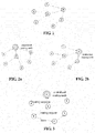
- FIG 1 briefly describes a process of constructing a network by nodes.
- a node 0 is a network starting node, which selects network parameters for the network, such as a network name, safety settings, and communication channels, etc. in different network protocols, the network starting node has different names. For example, in a Zigbee network, the network starting node is named as a coordinator.
- nodes 1 and 2 and 3 are neighboring nodes of the node 0, which obtain the network parameters from the node 0, and then join in the network.
- Nodes 4, 5 and 6 have not joined in the network, and they search nodes in the neighboring nodes having joined in the network to select an optimal node to obtain the network parameters.
- the nodes 4 and 5 join in the network through the node 2, and the node 6 joins in the network through the node 3.
- a node A obtains the network parameters through node B and then joins in the network
- the node B is referred to as a parent node of the node A
- the node A is referred to as a child node of the node B.
- the node 0 is a parent node of the nodes 1, 2 and 3
- the node 2 is a parent node of the nodes 4 and 5
- the node 3 is a parent node of the node 6.
- a parent-child relationship between the nodes forms a tree structure, a root node of which being a starting node of the network, as shown in FIG 1 .
- the centralized routing node obtains topology information of the whole network, and calculates routing paths for the ordinary node in the network. Hence, the ordinary node in the network needs to transmit local topology information to the centralized routing node.
- the topology information of the ordinary node refers to a state of a link between the node and its neighboring node.
- the process of obtaining the topology information by the centralized routing node is a process of data collection, hence, the network also forms a tree structure, as shown in FIGs 2a and 2b . In FIGs 2a and 2b , a connection line between nodes directs from a node to its routing node.
- the node 2 is a routing node of the node 6, and in reporting the topology information, the node 6 first transmits a data packet to the node 2; then the node 2 forwards the data packet to its routing node; and finally, the data packet is transmitted to the centralized routing node.
- Uploading the topology information by a node is of a tree structure, and a process of joining in the network by a node is also of a tree structure. It can be seen from comparison of FIGs. 1 and 2b , if the centralized routing node is the starting node of the network, a node may use the tree structure in joining in the network to upload the topology information of the node. And in this case, the routing node of the node is a parent node of the node in joining in the network.
- FIG. 3 is an example of transmitting data by an ordinary node.
- the node 5 needs to transmit a data packet to the node 3.
- the node 3 is not a neighboring node of the node 5, hence, the node 5 cannot directly transmit the data packet to the node 3, and transmission of the data packet can only be finished through forwarding by a routing node.
- the node 5 In order to obtain information on the routing node, the node 5 first transmits a routing request packet to the centralized routing node; after receiving the routing request packet, the centralized routing node calculates optimal routing from the node 5 to the node 3 according to the network topology information, and transmits routing information to the node 5 via a routing response packet; and the node 5 obtains the routing information from the routing response packet, and transmits the data packet to its routing node 6, and the data packet is finally forwarded to the global destination node 3.
- embodiments of the present disclosure provide a centralized routing method and apparatus and a system, which shall be described below with reference to the accompanying drawings.
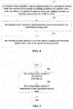
- FIG. 4 is a flowchart of the method. Referring to FIG. 4 , the method includes:
- the ordinary node has a function of neighbor table maintenance.
- quality and states of links between nodes are basic information for calculating routing
- the ordinary node may monitor quality of the link between it and a neighboring node, and save related information in a neighbor table.
- the ordinary node may use different parameters to evaluate the link quality, such as latency, a packet receiving ratio, and a signal intensity, etc.
- the ordinary node may report local neighboring node information to the centralized routing node, and if the neighboring node information changes, the ordinary node may upload updated neighboring node information to the centralized routing node.
- the ordinary node further has a function of data forwarding, and may perform such operations as data packet reception, transmission, and forwarding, etc. And in performing the data packet transmission and forwarding, the ordinary node may request the centralized routing node for routing information, i.e. information on a receiving node of the data packet, by using the method of this embodiment.
- the ordinary node may use a routing table to manage the obtained routing information.
- Table 1 is an example of a structure of a routing table of the ordinary node, in table 1, such information as an address of a current node, an address of a global destination node, a routing type, the number of hops, a routing address list, and routing valid time, etc. are included.
- the routing address list L i is routing from the current node N to the global destination node GD i
- H i is a length of routing list.
- the routing address list contains only an address R i of a parent node of routing from N to GD i , and the number of hops is 1; and when the current node N needs to transmit data to GD i , the data packet is first forwarded by the node R i .
- the routing valid time is a time length of the routing applied by the node for use.
- the ordinary node transmits the routing request packet to the centralized routing node.
- Table 2 is an example of the routing request packet, in table 2, an address of the global source node, an address of the global destination node and a routing valid time are included.
- FIG. 5 is a flowchart of transmitting the routing request packet by the ordinary node. Referring to FIG 5 , the flow includes:
- the centralized routing node after receiving the routing request packet transmitted by the ordinary node, the centralized routing node will select routing for the ordinary node according to a routing request of the routing request packet (which shall be described in Embodiment 2), and respond corresponding routing information to the ordinary node via a routing response packet.
- Table 3 is an example of the routing response packet, which is a data packet responding the routing request packet and contains information on the routing from the global source node to the global destination node.
- a routing address list in the routing response packet is a routing path from the global source node to the global destination node, and the number of hops is a length of the routing path.
- Table 3 Routing response packet Address of the global source node Address of the global destination node Routing type Number of hops Routing address list GS GD T H R 1 R 2 ... R H
- the ordinary node may parse the routing response packet to obtain the routing path from the global source node to the global destination node, such as what is the routing type, how many hops there will be from the ordinary node to the global destination node, and which routing nodes there will be, etc.
- the ordinary node may further incorporate contents of the routing response packet into its routing table.
- the routing table of the ordinary node contains a routing entry corresponding to the global destination node in the routing response packet, and the ordinary node may replace information on the corresponding routing entry in the routing table with information in the routing response packet; wherein routing valid time in the corresponding routing entry is a valid time of routing requested in the routing request packet.
- the routing table of the ordinary node does not contain a routing entry corresponding to the global destination node in the routing response packet, and the ordinary node may add a routing entry corresponding to the information in the routing response packet into its routing table; wherein routing valid time in the added routing entry is a valid time of routing requested in the routing request packet.
- the ordinary node may further monitor routing use time of the routing, and after the routing use time expires, delete routing entry to which the routing corresponds from the routing table.
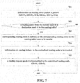
- FIG 6 is a flowchart of processing of the ordinary node after receiving the routing response packet. Referring to FIG. 6 , the flow includes:
- the routing node may respond a routing error packet regarding the routing response packet.
- Table 4 is an example of the routing error packet.
- the address of the global source node GS and the address of the global destination node GD are able to uniquely determine a routing path
- the address of the reporting node RR is a node transmitting a data forwarding error
- the address of the failure node ER is a receiving node of forwarded data
- the error type E indicates a reason for data forwarding failure.
- FIG 7 is a flowchart of the ordinary node after receiving the routing error packet. Referring to FIG. 7 , the flow includes:
- An embodiment of the present disclosure provides a centralized routing apparatus, applicable to an ordinary node in a collection network.
- the implementation of the method of Embodiment 1 may be referred to for the implementation of the apparatus, with identical contents being not going to be described herein any further.
- FIG. 8 is a schematic diagram of a structure of the centralized routing apparatus of this embodiment.
- the apparatus 800 includes a transmitting unit 801, a receiving unit 802 and a parsing unit 803; wherein, the transmitting unit 801 is configured to transmit a routing request packet to a centralized routing node, the routing request packet including an address of a global source node, an address of a global destination node, and routing valid time, of routing requested by the ordinary node; the receiving unit 802 is configured to receive a routing response packet responded by the centralized routing node; and the parsing unit 803 is configured to parse the routing response packet to obtain a routing path from the global source node to the global destination node.
- the apparatus may further include an updating unit 804 configured to combine information in the routing response packet into a routing table.
- the updating unit 804 replaces information on the corresponding routing entry in the routing table with information in the routing response packet; wherein routing valid time of the corresponding routing entry is routing valid time in the routing request packet.
- the updating unit 804 adds a routing entry corresponding to the information in the routing response packet into the routing table, wherein routing valid time of the routing entry is routing valid time in the routing request packet.
- the updating unit 804 may further delete the routing entry from the routing table when the routing valid time of the routing entry expires.
- the receiving unit 802 may further receive a routing error packet.
- the parsing unit 803 may parse the routing error packet to obtain an address of a global source node, an address of a global destination node, an address of a reporting node, an address of a failure node, in which a routing error occurs, and a type of error.
- the updating unit 804 may delete a corresponding routing entry or set a state of the corresponding routing entry as being invalid when the address of the global source node and the address of the global destination node exist in the routing table.
- the transmitting unit 801 may transmit routing error information and/or routing request packets including a routing request to the centralized routing node.
- the apparatus 800 may further include a storing unit 805 configured to store the above routing table, and the above neighbor table, etc.
- FIG. 9 is a flowchart of the method. Referring to FIG 9 , the method includes:
- the ordinary node may upload information on its neighbor table to the centralized routing node, the neighbor table containing states of links between the ordinary node and its neighboring nodes.
- the centralized routing node may collect information on neighbor tables of all ordinary nodes in the network, so as to obtain a topological relationship of the whole network, maintain and manage topology information on the whole network, and calculate routing paths between the nodes by using a routing algorithm according to the topology information, thereby selecting routing for the ordinary node according to the routing request packet containing a routing request reported by the ordinary node, and manage and maintain the calculated routing paths.
- the network topology refers to connection relationships between the nodes in the network.
- the centralized routing node may manage the topology information of the network by using a network topology table.
- the network topology table contains quality of a link between any two nodes.
- the centralized routing node may calculate the routing paths by using any routing algorithm according to the network topology information, such as a Dijkstra algorithm, and a Bellman-Ford algorithm, etc.; however, this embodiment is not limited thereto.
- the centralized routing node may manage the calculated routing paths by using a routing table.
- Table 5 is an example of the routing table of the centralized routing node. Information on routing from a node GS i to a global destination node GD ij is stored in this routing table; where, L ij is an address of a node in a routing path, H ij is a length of a routing path, and X ij is a valid time used by a path.
- the centralized routing node may parse the routing request packet after receiving the routing request packet from the ordinary node, so as to obtain the address of the global source node, the address of the global destination node, and the routing valid time, of the routing requested by the ordinary node, and select a routing path for the ordinary node accordingly.
- the centralized routing node may determine the routing path from the global source node to the global destination node accordingly.
- the centralized routing node may calculate the routing path from the global source node to the global destination node according to the information in the network topology table, with a particular calculation method being not limited herein. Alternatively, the centralized routing node may further save the calculated routing path in the routing table.
- the valid time is the routing valid time in the routing request packet. Alternatively, after the valid time of the routing path expires, the centralized routing node may further delete it from its routing table.
- the centralized routing node may respond the ordinary node with a routing response packet after selecting the routing path for the ordinary node according to the routing request packet of the ordinary node.
- the contents of the routing response packet have been described in Embodiment 1, and shall not be described herein any further.
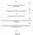
- FIG 10 is a flowchart of processing by the centralized routing node after receiving the routing request packet. Referring to FIG 10 , the flow includes:
- the centralized routing node may parse the routing error packet, so as to obtain the address of the global source node, the address of the global destination node, the address of the reporting node, and the address of the failure node, in which the routing error occurs, and delete the routing paths from the global source node to the global destination node from the routing table when the routing table contains the routing paths from the global source node to the global destination node, and a failed link exists in the routing paths in the routing table.
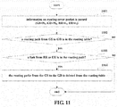
- FIG 11 is a flowchart of processing by the centralized routing node after receiving the routing error packet. Referring to FIG. 11 , the flow includes:
- the centralized routing node may further update routing paths in the routing table affected by the change of the network topology.
- the centralized routing node deletes entries in the routing table corresponding to the routing paths.
- the centralized routing node may calculate a routing cost of the routing paths and a routing cost of an optimal routing path between the global source node and the global destination node to which the routing paths correspond, and update routing information in the routing table to which the routing paths correspond according to the optimal routing path when a difference between the above two costs is greater than a first threshold and a remaining routing valid time is greater than a second threshold. Thereafter, alternatively, the centralized routing node may transmit a routing response packet containing the optimal routing path to the global source node (the global source node to which the routing path corresponds).
- the first threshold and the second threshold are predetermined, a conventional method may be used as a method for calculating the routing cost, and content of the routing response packet is as described above.
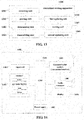
- FIG 12 is a flowchart of updating routing by the centralized routing node in discovering that the network topology changes. Referring to FIG. 12 , the flow includes:
- An embodiment of the present disclosure provides a centralized routing apparatus, applicable to a centralized routing node in a collection network.
- the implementation of the method of Embodiment 3 may be referred to for the implementation of the apparatus, with identical contents being not going to be described herein any further.
- FIG. 13 is a schematic diagram of a structure of the centralized routing apparatus of this embodiment.
- the apparatus 1300 includes a receiving unit 1301, a parsing unit 1302, a determining unit 1303 and a transmitting unit 1304; wherein, the receiving unit 1301 is configured to receive a routing request packet from an ordinary node; wherein, content of the routing request packet has been described in detail in Embodiment 1, and is incorporated herein, which shall not be described herein any further;
- the parsing unit 1302 is configured to parse the routing request packet, so as to obtain an address of a global source node, an address of a global destination node, and routing valid time, of routing requested by the ordinary node;
- the determining unit 1303 is configured to determine a routing path from the global source node to the global destination node according to the routing request packet; wherein, if a routing table contains the routing path from the global source node to the global destination node, the determining unit 1303 determines the routing path from the global source
- the receiving unit 1301 may further receive a routing error packet; the parsing unit 1302 may further parse the routing error packet, so as to obtain an address of a global source node, an address of a global destination node, an address of a reporting node, and an address of a failure node, in which a routing error occurs.
- the apparatus 1300 further includes: a first updating unit 1305 configured to look up the routing table, and when the routing table includes the routing path from the global source node to the global destination node and a link in which the error occurs exists in the routing path of the routing table, delete the routing path between the global source node and the global destination node in the routing table.
- the apparatus 1300 further includes: a second updating unit 1306 configured to, when network topology changes, update a routing path in the routing table that is affected by the change of the network topology.
- the second updating unit 1306 may look up the routing table, deletes an entry in the routing table corresponding to the routing path when the routing path reaches the routing valid time, calculate a routing cost of the routing path and a routing cost of an optimal routing path between the global source node and the global destination node to which the routing path corresponds when the routing path does not reach the routing valid time, and updates routing information in the routing table to which the routing path corresponds according to the optimal routing path if a difference between the routing cost of the routing path and the routing cost of the optimal routing path is greater than a first threshold and remaining routing valid time is greater than a second threshold; thus the transmitting unit 1304 transmits a routing response packet including the optimal routing path to the global source node.
- the apparatus 1300 may further include a storing unit 1307 configured to store a routing table of the centralized routing node, and a network topology table, etc.
- An embodiment of the present disclosure provides an ordinary node, including the centralized routing apparatus as described in Embodiment 2.
- FIG. 14 is a schematic diagram of a structure of the ordinary node of the embodiment of the present disclosure.
- the ordinary node 1400 may include a central processing unit 1401 and a memory 1402, the memory 1402 being coupled to the central processing unit 1401.
- this figure is illustrative only, and other types of structures may also be used, so as to supplement or replace this structure and achieve telecommunications function or other functions.
- the functions of the centralized routing apparatus may be integrated into the central processing unit 1401.
- the centralized routing apparatus and the central processing unit 1401 may be configured separately.
- the centralized routing apparatus may be configured as a chip connected to the central processing unit 1401, with its functions being realized under control of the central processing unit 1401.
- the ordinary node 1400 may further include a communication module 1403, an input unit 1404, an audio processing unit 1405, a display 1406, and a power supply 1407. It should be noted that the ordinary node 1400 does not necessarily include all the parts shown in FIG. 14 , and furthermore, the ordinary node 1400 may include parts not shown in FIG. 14 , and the related art may be referred to.
- the central processing unit 1401 is sometimes referred to as a controller or control, and may include a microprocessor or other processor devices and/or logic devices.
- the central processing unit 1401 receives input and controls operations of every components of the ordinary node 1400.
- the memory 1402 may be, for example, one or more of a buffer memory, a flash memory, a hard drive, a mobile medium, a volatile memory, a nonvolatile memory, or other suitable devices, which may store the above routing table, and the neighboring table, etc., and may further store a program executing related information.
- the central processing unit 1401 may execute the program stored in the memory 1402, so as to realize information storage or processing, etc. Functions of other parts are similar to those of the related art, which shall not be described herein any further.
- the parts of the ordinary node 1400 may be realized by specific hardware, firmware, software, or any combination thereof, without departing from the scope of the present disclosure.
- An embodiment of the present disclosure provides a centralized routing node, including the centralized routing apparatus as described in Embodiment 4.
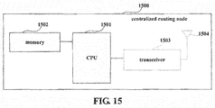
- FIG. 15 is a schematic diagram of a structure of the centralized routing node of the embodiment of the present disclosure.
- the centralized routing node 1500 may include a central processing unit (CPU) 1501 and a memory 1502, the memory 1502 being coupled to the central processing unit 1501.
- the memory 1502 may store various data, such as the above described routing table, and network topology table, etc.; furthermore, it may store a program executing related information, and execute the program under control of the central processing unit 1501, so as to receive various data transmitted by other nodes, and transmit various data packets to the other nodes.
- the functions of the centralized routing apparatus of Embodiment 4 may be integrated into the central processing unit 1501.
- the centralized routing apparatus of Embodiment 4 and the central processing unit 1501 may be configured separately.
- the centralized routing apparatus may be configured as a chip connected to the central processing unit 1501, with its functions being realized under control of the central processing unit 1501.
- the centralized routing node 1500 may further include a transceiver 1503, and an antenna 1504, etc.; wherein, functions of the above parts are similar to those in the related art, and shall not be described herein any further. It should be noted that the centralized routing node 1500 does not necessarily include all the parts shown in FIG. 15 , and furthermore, the centralized routing node 1500 may include parts not shown in FIG. 15 , and the related art may be referred to.
- An embodiment of the present disclosure provides a communication system, including a centralized routing node and an ordinary node, the centralized routing node being realized by the centralized routing node 1500 of Embodiment 6, and the ordinary node being realized by the ordinary node 1400 of Embodiment 5.
- the centralized routing node 1500 and the ordinary node 1400 have been described in detail in Embodiment 6 and Embodiment 5, contents of them are incorporated herein, which shall not be described herein any further.
- An embodiment of the present disclosure provides a computer-readable program, wherein when the program is executed in a centralized routing apparatus or a centralized routing node, the program enables a computer to carry out the method as described in Embodiment 3 in the centralized routing apparatus or the centralized routing node.
- An embodiment of the present disclosure provides a storage medium in which a computer-readable program is stored, wherein the computer-readable program enables a computer to carry out the method as described in Embodiment 3 in a centralized routing apparatus or a centralized routing node.
- An embodiment of the present disclosure further provides a computer-readable program, wherein when the program is executed in a centralized routing apparatus or an ordinary node, the program enables a computer to carry out the method as described in Embodiment 1 in the centralized routing apparatus or the ordinary node.
- An embodiment of the present disclosure provides a storage medium in which a computer-readable program is stored, wherein the computer-readable program enables a computer to carry out the method as described in Embodiment 1 in a centralized routing apparatus or an ordinary node.
- the above apparatuses and methods of the present disclosure may be implemented by hardware, or by hardware in combination with software.
- the present disclosure relates to such a computer-readable program that when the program is executed by a logic device, the logic device is enabled to carry out the apparatus or components as described above, or to carry out the methods or steps as described above.
- the present disclosure also relates to a storage medium for storing the above program, such as a hard disk, a floppy disk, a CD, a DVD, and a flash memory, etc.
Landscapes
- Engineering & Computer Science (AREA)
- Computer Networks & Wireless Communication (AREA)
- Signal Processing (AREA)
- Environmental & Geological Engineering (AREA)
- Data Exchanges In Wide-Area Networks (AREA)
- Mobile Radio Communication Systems (AREA)
Applications Claiming Priority (1)
| Application Number | Priority Date | Filing Date | Title |
|---|---|---|---|
| CN201510184282.XA CN106161237B (zh) | 2015-04-17 | 2015-04-17 | 集中式的路由方法、装置和系统 |
Publications (1)
| Publication Number | Publication Date |
|---|---|
| EP3082308A1 true EP3082308A1 (fr) | 2016-10-19 |
Family
ID=55637300
Family Applications (1)
| Application Number | Title | Priority Date | Filing Date |
|---|---|---|---|
| EP16162686.6A Withdrawn EP3082308A1 (fr) | 2015-04-17 | 2016-03-29 | Procédé et appareil et système de routage centralisé |
Country Status (4)
| Country | Link |
|---|---|
| US (1) | US20160308760A1 (fr) |
| EP (1) | EP3082308A1 (fr) |
| JP (1) | JP2016208509A (fr) |
| CN (1) | CN106161237B (fr) |
Cited By (2)
| Publication number | Priority date | Publication date | Assignee | Title |
|---|---|---|---|---|
| CN107659497A (zh) * | 2017-11-03 | 2018-02-02 | 深圳天珑无线科技有限公司 | 路由修复方法和装置 |
| EP3965400A1 (fr) * | 2020-09-08 | 2022-03-09 | Thales Alenia Space Deutschland GmbH | Procédé de transmission de données dans un réseau ad hoc |
Families Citing this family (7)
| Publication number | Priority date | Publication date | Assignee | Title |
|---|---|---|---|---|
| CN107612743B (zh) * | 2017-10-11 | 2021-01-26 | 深圳天珑无线科技有限公司 | 网络拓扑信息收集方法、以及路由修复方法 |
| CN110149273A (zh) * | 2018-02-11 | 2019-08-20 | 乐鑫信息科技(上海)股份有限公司 | 一种mesh网络内路由表的添加与删除方法 |
| CN110475232A (zh) * | 2018-05-09 | 2019-11-19 | 厦门本能管家科技有限公司 | 一种基于蓝牙、nfc、airdrop的区块链网络传输方法及系统 |
| CN110582034B (zh) * | 2018-06-11 | 2022-04-26 | 台达电子工业股份有限公司 | 智能定义光隧道网络系统控制器及其控制方法 |
| CN109041157A (zh) * | 2018-07-18 | 2018-12-18 | 宁波大红鹰学院 | 一种自组网通信协议 |
| CN110636005B (zh) * | 2019-08-21 | 2021-03-02 | 北京邮电大学 | 知识中心网络的知识路由方法及装置 |
| CN111787511B (zh) * | 2020-07-13 | 2021-09-07 | 重庆大学 | 一种Zigbee网络及其节点切换方法 |
Family Cites Families (7)
| Publication number | Priority date | Publication date | Assignee | Title |
|---|---|---|---|---|
| DE102007029120B4 (de) * | 2007-06-25 | 2010-06-17 | Siemens Ag | Verfahren zum Betreiben eines drahtlosen, vermaschten Datennetzes mit einer Mehrzahl an Netzknoten |
| CN101765117A (zh) * | 2008-12-26 | 2010-06-30 | 华为技术有限公司 | 一种分配信道和实现通信的方法、装置和系统 |
| CN101969680A (zh) * | 2009-11-13 | 2011-02-09 | 南京中兴软件有限责任公司 | 无线网状网络路由实现方法和无线网状网络节点 |
| CN102075428B (zh) * | 2011-01-20 | 2012-11-14 | 中国电信股份有限公司 | 联合路由设置方法和装置 |
| CN104518967B (zh) * | 2013-09-30 | 2017-12-12 | 华为技术有限公司 | 路由方法、设备和系统 |
| CN104283789B (zh) * | 2014-09-19 | 2016-04-13 | 深圳市腾讯计算机系统有限公司 | 路由收敛方法和系统 |
| CN104320334B (zh) * | 2014-11-03 | 2017-06-13 | 电子科技大学 | 一种无线Mesh网络中的集中式路由算法 |
-
2015
- 2015-04-17 CN CN201510184282.XA patent/CN106161237B/zh active Active
-
2016
- 2016-03-24 US US15/079,920 patent/US20160308760A1/en not_active Abandoned
- 2016-03-29 EP EP16162686.6A patent/EP3082308A1/fr not_active Withdrawn
- 2016-04-14 JP JP2016081382A patent/JP2016208509A/ja active Pending
Non-Patent Citations (1)
| Title |
|---|
| "Centralized Metric based Source Routing", ITU-T DRAFT ; STUDY PERIOD 2013-2016, INTERNATIONAL TELECOMMUNICATION UNION, GENEVA ; CH, vol. 15/15, 6 May 2013 (2013-05-06), pages 1 - 19, XP044113200 * |
Cited By (2)
| Publication number | Priority date | Publication date | Assignee | Title |
|---|---|---|---|---|
| CN107659497A (zh) * | 2017-11-03 | 2018-02-02 | 深圳天珑无线科技有限公司 | 路由修复方法和装置 |
| EP3965400A1 (fr) * | 2020-09-08 | 2022-03-09 | Thales Alenia Space Deutschland GmbH | Procédé de transmission de données dans un réseau ad hoc |
Also Published As
| Publication number | Publication date |
|---|---|
| US20160308760A1 (en) | 2016-10-20 |
| CN106161237B (zh) | 2020-08-18 |
| CN106161237A (zh) | 2016-11-23 |
| JP2016208509A (ja) | 2016-12-08 |
Similar Documents
| Publication | Publication Date | Title |
|---|---|---|
| EP3082308A1 (fr) | Procédé et appareil et système de routage centralisé | |
| US11411853B2 (en) | Link-state advertisement LSA sending method, apparatus, and system | |
| US20210274418A1 (en) | Information Transmission Method and Apparatus | |
| US7330694B2 (en) | Method for setting up route path through route discovery in a mobile ad hoc network using partial route discovery | |
| KR101986929B1 (ko) | 패킷을 라우팅하는 방법, 멀티 홉 무선 네트워크 및 패킷을 라우팅하는 노드 | |
| US11445430B2 (en) | Data forwarding method and apparatus | |
| EP3055950B1 (fr) | Acheminement ad hoc à la demande par contrôle central | |
| US10291510B2 (en) | Topology structure discovery method and device | |
| US9264314B2 (en) | Method, system, and switch for making bridge in MSTP join region | |
| US20040233847A1 (en) | Routing system for establishing optimal route in wireless personal area network (WPAN) and method thereof | |
| JP7124206B2 (ja) | パケット処理方法およびゲートウェイ・デバイス | |
| WO2015151423A1 (fr) | Procédé de communication sans fil | |
| CN111510982B (zh) | 一种传输数据的方法及装置 | |
| KR20150084647A (ko) | 상호-청취자 장치 세트에 대하여 가상 인터페이스를 설정하는 방법 및 장치 | |
| US20210288837A1 (en) | Internet of things network system and networking method thereof | |
| CN106604350B (zh) | 一种在配用电无线自组织网中建立树形路由的方法 | |
| CN101340361B (zh) | 数据包中转限制方法及设备 | |
| CN113872868A (zh) | 通知消息传输方法、装置及系统、存储介质 | |
| CN106330536A (zh) | 一种wmSDN的网络状态信息的采集方法 | |
| US9374849B2 (en) | Node and link formation method | |
| JP7542395B2 (ja) | 複数のノードを含むネットワークのための方法、ブルートゥース低エネルギーネットワーク、およびコンピュータプログラム製品 | |
| CN104661185A (zh) | 融合树的构建方法、融合数据的收集和传输方法及其节点 | |
| JP6459558B2 (ja) | 無線通信装置、無線通信方法、および無線通信プログラム | |
| JP2020088574A (ja) | 中継装置、ネットワークシステム、中継方法およびプログラム | |
| CN119232628A (zh) | 网络校验方法及通信系统 |
Legal Events
| Date | Code | Title | Description |
|---|---|---|---|
| PUAI | Public reference made under article 153(3) epc to a published international application that has entered the european phase |
Free format text: ORIGINAL CODE: 0009012 |
|
| AK | Designated contracting states |
Kind code of ref document: A1 Designated state(s): AL AT BE BG CH CY CZ DE DK EE ES FI FR GB GR HR HU IE IS IT LI LT LU LV MC MK MT NL NO PL PT RO RS SE SI SK SM TR |
|
| AX | Request for extension of the european patent |
Extension state: BA ME |
|
| 17P | Request for examination filed |
Effective date: 20170302 |
|
| RBV | Designated contracting states (corrected) |
Designated state(s): AL AT BE BG CH CY CZ DE DK EE ES FI FR GB GR HR HU IE IS IT LI LT LU LV MC MK MT NL NO PL PT RO RS SE SI SK SM TR |
|
| STAA | Information on the status of an ep patent application or granted ep patent |
Free format text: STATUS: THE APPLICATION HAS BEEN WITHDRAWN |
|
| 18W | Application withdrawn |
Effective date: 20180123 |