EP3082196A1 - Verpolungssicherer stromstecker - Google Patents
Verpolungssicherer stromstecker Download PDFInfo
- Publication number
- EP3082196A1 EP3082196A1 EP16165716.8A EP16165716A EP3082196A1 EP 3082196 A1 EP3082196 A1 EP 3082196A1 EP 16165716 A EP16165716 A EP 16165716A EP 3082196 A1 EP3082196 A1 EP 3082196A1
- Authority
- EP
- European Patent Office
- Prior art keywords
- connector
- keyed
- terminal stud
- diameter
- post
- Prior art date
- Legal status (The legal status is an assumption and is not a legal conclusion. Google has not performed a legal analysis and makes no representation as to the accuracy of the status listed.)
- Granted
Links
- 238000004891 communication Methods 0.000 claims description 4
- 238000000034 method Methods 0.000 description 9
- 230000008901 benefit Effects 0.000 description 6
- 239000000919 ceramic Substances 0.000 description 4
- 239000002184 metal Substances 0.000 description 4
- 239000004020 conductor Substances 0.000 description 3
- 238000000576 coating method Methods 0.000 description 2
- 238000012423 maintenance Methods 0.000 description 2
- 239000000463 material Substances 0.000 description 2
- 238000005259 measurement Methods 0.000 description 2
- 239000011800 void material Substances 0.000 description 2
- 230000006978 adaptation Effects 0.000 description 1
- 238000010276 construction Methods 0.000 description 1
- 230000008878 coupling Effects 0.000 description 1
- 238000010168 coupling process Methods 0.000 description 1
- 238000005859 coupling reaction Methods 0.000 description 1
- 238000013461 design Methods 0.000 description 1
- 238000010586 diagram Methods 0.000 description 1
- 238000009434 installation Methods 0.000 description 1
Images
Classifications
-
- H—ELECTRICITY
- H01—ELECTRIC ELEMENTS
- H01R—ELECTRICALLY-CONDUCTIVE CONNECTIONS; STRUCTURAL ASSOCIATIONS OF A PLURALITY OF MUTUALLY-INSULATED ELECTRICAL CONNECTING ELEMENTS; COUPLING DEVICES; CURRENT COLLECTORS
- H01R11/00—Individual connecting elements providing two or more spaced connecting locations for conductive members which are, or may be, thereby interconnected, e.g. end pieces for wires or cables supported by the wire or cable and having means for facilitating electrical connection to some other wire, terminal, or conductive member, blocks of binding posts
- H01R11/11—End pieces or tapping pieces for wires, supported by the wire and for facilitating electrical connection to some other wire, terminal or conductive member
- H01R11/28—End pieces consisting of a ferrule or sleeve
- H01R11/281—End pieces consisting of a ferrule or sleeve for connections to batteries
- H01R11/289—End pieces consisting of a ferrule or sleeve for connections to batteries characterised by the shape or the structure of the battery post
-
- H—ELECTRICITY
- H01—ELECTRIC ELEMENTS
- H01R—ELECTRICALLY-CONDUCTIVE CONNECTIONS; STRUCTURAL ASSOCIATIONS OF A PLURALITY OF MUTUALLY-INSULATED ELECTRICAL CONNECTING ELEMENTS; COUPLING DEVICES; CURRENT COLLECTORS
- H01R13/00—Details of coupling devices of the kinds covered by groups H01R12/70 or H01R24/00 - H01R33/00
- H01R13/64—Means for preventing incorrect coupling
- H01R13/645—Means for preventing incorrect coupling by exchangeable elements on case or base
- H01R13/6456—Means for preventing incorrect coupling by exchangeable elements on case or base comprising keying elements at different positions along the periphery of the connector
-
- H—ELECTRICITY
- H01—ELECTRIC ELEMENTS
- H01R—ELECTRICALLY-CONDUCTIVE CONNECTIONS; STRUCTURAL ASSOCIATIONS OF A PLURALITY OF MUTUALLY-INSULATED ELECTRICAL CONNECTING ELEMENTS; COUPLING DEVICES; CURRENT COLLECTORS
- H01R13/00—Details of coupling devices of the kinds covered by groups H01R12/70 or H01R24/00 - H01R33/00
- H01R13/62—Means for facilitating engagement or disengagement of coupling parts or for holding them in engagement
- H01R13/621—Bolt, set screw or screw clamp
- H01R13/6215—Bolt, set screw or screw clamp using one or more bolts
-
- H—ELECTRICITY
- H01—ELECTRIC ELEMENTS
- H01R—ELECTRICALLY-CONDUCTIVE CONNECTIONS; STRUCTURAL ASSOCIATIONS OF A PLURALITY OF MUTUALLY-INSULATED ELECTRICAL CONNECTING ELEMENTS; COUPLING DEVICES; CURRENT COLLECTORS
- H01R13/00—Details of coupling devices of the kinds covered by groups H01R12/70 or H01R24/00 - H01R33/00
- H01R13/62—Means for facilitating engagement or disengagement of coupling parts or for holding them in engagement
- H01R13/629—Additional means for facilitating engagement or disengagement of coupling parts, e.g. aligning or guiding means, levers, gas pressure electrical locking indicators, manufacturing tolerances
- H01R13/631—Additional means for facilitating engagement or disengagement of coupling parts, e.g. aligning or guiding means, levers, gas pressure electrical locking indicators, manufacturing tolerances for engagement only
-
- H—ELECTRICITY
- H01—ELECTRIC ELEMENTS
- H01R—ELECTRICALLY-CONDUCTIVE CONNECTIONS; STRUCTURAL ASSOCIATIONS OF A PLURALITY OF MUTUALLY-INSULATED ELECTRICAL CONNECTING ELEMENTS; COUPLING DEVICES; CURRENT COLLECTORS
- H01R13/00—Details of coupling devices of the kinds covered by groups H01R12/70 or H01R24/00 - H01R33/00
- H01R13/64—Means for preventing incorrect coupling
-
- H—ELECTRICITY
- H01—ELECTRIC ELEMENTS
- H01R—ELECTRICALLY-CONDUCTIVE CONNECTIONS; STRUCTURAL ASSOCIATIONS OF A PLURALITY OF MUTUALLY-INSULATED ELECTRICAL CONNECTING ELEMENTS; COUPLING DEVICES; CURRENT COLLECTORS
- H01R11/00—Individual connecting elements providing two or more spaced connecting locations for conductive members which are, or may be, thereby interconnected, e.g. end pieces for wires or cables supported by the wire or cable and having means for facilitating electrical connection to some other wire, terminal, or conductive member, blocks of binding posts
- H01R11/11—End pieces or tapping pieces for wires, supported by the wire and for facilitating electrical connection to some other wire, terminal or conductive member
- H01R11/28—End pieces consisting of a ferrule or sleeve
- H01R11/281—End pieces consisting of a ferrule or sleeve for connections to batteries
- H01R11/283—Bolt, screw or threaded ferrule parallel to the battery post
-
- H—ELECTRICITY
- H01—ELECTRIC ELEMENTS
- H01R—ELECTRICALLY-CONDUCTIVE CONNECTIONS; STRUCTURAL ASSOCIATIONS OF A PLURALITY OF MUTUALLY-INSULATED ELECTRICAL CONNECTING ELEMENTS; COUPLING DEVICES; CURRENT COLLECTORS
- H01R24/00—Two-part coupling devices, or either of their cooperating parts, characterised by their overall structure
- H01R24/66—Two-part coupling devices, or either of their cooperating parts, characterised by their overall structure with pins, blades or analogous contacts and secured to apparatus or structure, e.g. to a wall
- H01R24/68—Two-part coupling devices, or either of their cooperating parts, characterised by their overall structure with pins, blades or analogous contacts and secured to apparatus or structure, e.g. to a wall mounted on directly pluggable apparatus
Definitions
- the present disclosure relates generally to electrical connectors, and more specifically to keyed electrical connectors.
- the keyed power system may have a connector.
- the connector may include a connector fastening portion having a captive fastener, a connector electrical conduction portion including a connector body configured to retain the connector fastening portion in movable communication with the connector, and a connector keying portion having a keyed aperture forming an opening in and defined by the connector body and including a keyed connector diameter.
- a keyed power connection system may have a terminal stud.
- the terminal stud may include a terminal stud keying portion having a post including a cylindrical boss configured to support a terminal stud fastening portion, a keyed stud diameter including a diameter of the post, and a terminal stud electrical conduction portion having a terminal stud conductive surface disposed annularly about the post.
- the terminal stud fastening portion may include a fastener receiving threaded bore having a cylindrical channel defined by the post and extending axially into the post.
- any reference to singular includes plural embodiments, and any reference to more than one component or step may include a singular embodiment or step.
- Surface shading lines may be used throughout the figures to denote different parts but not necessarily to denote the same or different materials.
- Power distribution systems such as on vehicles (e.g., aircraft), often involve large gauge electrical power feeders.
- Such large gauge feeders are often connected via lugs attached to terminal studs, and due to their large gauge are often not connected via multi-conductor connectors.
- connections may potentially be misconnected.
- a power feeder and a power return, or multiple phase power feeders, and/or the like may be located in close proximity.
- multiple such connections may be disconnected and reconnected.
- lugs may be attached to the incorrect terminal studs.
- a connector may be sized to only receive studs of corresponding size and may be associated with a captive fastener.
- various different connectors may be differently sized to prevent misconnection.
- the fastener is captive, the fastener is less subject to being lost.
- a single tool of a single size may be used to tighten/loosen connectors of a variety of different sizes, because differently sized connectors may have similarly sized fasteners.
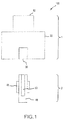
- a keyed power connection system 100 may comprise a connector 1 and a terminal stud 2.
- the keyed power connection system 100 may enable the connection and disconnection of electrical power conducted between the connector 1 and the terminal stud 2 and may further prevent misconnection of connector(s) 1 to incorrect terminal stud(s) 2.
- the connector 1 may comprise a connector fastening portion 10, a connector electrical conduction portion 20, and a connector keying portion 30.
- the terminal stud 2 may comprise a terminal stud keying portion 40, a terminal stud electrical conduction portion 45, and a terminal stud fastening portion 50.
- the connector fastening portion 10 and the terminal stud fastening portion 50 may selectably interconnect and disconnect to hold the connector electrical conduction portion 20 in selectable physical contact with the terminal stud electrical conduction portion 45. In this manner, electrical power may be conducted between the connector 1 and the terminal stud 2.
- the connector keying portion 30 and the terminal stud keying portion 40 may interact to permit the interconnection of the connector 1 to a corresponding terminal stud 2 while preventing the interconnector of the connector 1 to an incorrect terminal stud 2.
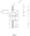
- a connector fastening portion 10 of a connector 1 may comprise a captive fastener 11.
- a captive fastener 11 may comprise a threaded bolt extending through a portion of the connector 1, for instance, through an opening in the top of the connector 1 and extending into the connector electrical conduction portion 20.
- the captive fastener 11 may be threaded to correspond to the terminal stud fastening portion 50 of a terminal stud 2.
- the captive fastener 11 may be connected/disconnected from the terminal stud fastening portion 50 of the terminal stud 2, thereby holding the connector electrical conduction portion 20 of the connector 1 in physical connection with the terminal stud electrical conduction portion 45 of the terminal stud 2.
- a connector electrical conduction portion 20 of a connector 1 may comprise a connector body 21.
- a connector body 21 may comprise a housing configured to retain the connector fastening portion 10 (e.g., the captive fastener 11) in movable communication with the connector 1.
- the captive fastener 11 may extend through a hole in the connector body 21 so that the captive fastener 11 extends through the connector body 21 and is positioned to interface with the terminal stud 2.
- the connector body 21 may be further configured to support the connector conductive surface 22 in a desired position, such as to provide rigidity to the connector conductive surface 22 when positioned in physical contact with the terminal stud conductive surface 46 of the terminal stud electrical conduction portion 45.
- the connector body 21 may comprise metal, although in further embodiments, it may comprise ceramic, or plastic, or may comprise coatings, such as a metal coated with a ceramic or plastic and/or the like.
- the connector body 21 may be conductive and may be pressed into mechanical contact with a corresponding plane of a post 41 such as may surround the base of the post 41 from which the post 41 orthogonally extends.
- a connector electrical conduction portion 20 may comprise a connector conductive surface 22.
- the connector conductive surface 22 may comprise an integral portion of the connector body 21, for example, such as for connector body 21 made of a conductive material.
- the connector conductive surface 22 may comprise an annular portion of a cylindrical void defined by the connector body 21 and arranged to receive at least a portion of a terminal stud 2.
- the connector electrical conduction portion 20 may comprise a connector conductive surface 22 comprising an insert.
- the connector conductive surface 22 may comprise an annular insert disposed within an aperture defined by the connector body 21 and arranged to receive at least a portion of a terminal stud 2.
- a connector keying portion 30 of a connector 1 may comprise a connector keyed aperture 31.
- the connector keyed aperture 31 may comprise an opening in and defined by the connector body 21.
- the connector keyed aperture 31 may provide a passage for a portion of the terminal stud 2 to pass into the connector 1 so that the connector electrical conduction portion 20 and the terminal stud electrical conduction portion 45 may make physical contact with one another.
- the connector keyed aperture 31 may comprise a shape corresponding to the shape of the terminal stud 2.
- the connector keyed aperture 31 may comprise a circular opening onto a cylindrical void defined by the connector body 21.
- the connector keyed aperture 31 may comprise any shape as desired.
- a connector keying portion 30 may comprise a keyed connector diameter 33.
- a keyed connector diameter 33 may comprise a diameter of the connector keyed aperture 31.
- the keyed connector diameter 33 may be sized to correspond to a measurement of the terminal stud 2.
- the keyed connector diameter 33 may comprise a dimension corresponding to a keyed stud diameter 42 of a terminal stud keying portion 40 of a terminal stud 2.
- the keyed connector diameter 33 comprises the same dimension as the keyed stud diameter 42 plus a tolerance.
- the connector 1 may be configured to properly connect only to those terminal studs 2 having a corresponding keyed stud diameter 42.
- the keyed connector diameter 33 corresponds to the same dimension plus a tolerance of, for instance, .1 mm or .01 mm. or .5 mm or .05 mm, or any tolerance as desired, allowing for the connector 1 to slip over and receive a portion of the terminal stud 2.
- a connector keying portion 30 may comprise a connector alignment chamfer 32.
- a connector alignment chamfer 32 may comprise an annular chamfer immediately outward of the connector keyed aperture 31 and defined by the connector body 21.
- the connector alignment chamfer 32 may facilitate seating of the connector 1 on to a terminal stud 2 and may facilitate guidance of a portion of the terminal stud 2 into the connector 1.
- the connector alignment chamfer 32 may correspond to the same dimension as the keyed stud diameter 42, plus a tolerance of, for instance, .1 mm or .01 mm. or .5 mm or .05 mm, plus an additional tolerance of, for instance, .1 mm or .01 mm. or .5 mm or .05 mm, or any tolerance as desired to facilitate manual alignment and guidance to the connector 1 and the terminal stud 2 together.
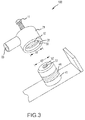
- focus is directed to the terminal stud 2. Particularly, focus is given to the terminal stud keying portion 40, the terminal stud electrical conduction portion 45, and the terminal stud fastening portion 50.
- a terminal stud keying portion 40 of a terminal stud 2 may comprise a post 41 configured to support a terminal stud fastening portion 50 (e.g., the fastener receiving threaded bore 51 and/or fastener receiving counter bore 52) whereby a connector fastening portion 10 (e.g., captive fastener 11) of a connector 1 is received.
- a post 41 may comprise a fixture, such as a cylindrical boss, arranged to support the terminal stud electrical conduction portion 45 in a desired position, such as to provide rigidity to the terminal stud conductive surface 46 when positioned in physical contact with the connector conductive surface 22.
- the post 41 comprises metal, although in further embodiments, it may comprise ceramic, or plastic, or may comprise coatings, such as a metal coated with a ceramic or plastic and/or the like.
- a terminal stud keying portion 40 may comprise a keyed stud diameter 42.
- a keyed stud diameter 42 may comprise a diameter of the terminal stud 2.
- the keyed stud diameter 42 may be sized to correspond to a measurement of the connector 1.
- the keyed stud diameter 42 may comprise a dimension corresponding to a keyed connector diameter 33 of a connector keying portion 30 of a connector 1.
- the keyed stud diameter 42 comprises the same dimension as the keyed connector diameter 33 minus a tolerance.
- the terminal stud 2 may be configured to properly connect only to those connectors 1 having a corresponding diameter, allowing for the connector 1 to slip over and receive a portion of the terminal stud 2.
- a terminal stud keying portion 40 may comprise a terminal stud alignment chamfer 43.
- a terminal stud alignment chamfer 43 may comprise an annular chamfer disposed at the tip of the post 41.
- the terminal stud alignment chamfer 43 may facilitate seating of the connector 1 on to a terminal stud 2 and may facilitate guidance of the connector 1 over the terminal stud 2.
- the terminal stud alignment chamfer 43 may correspond to the same dimension as the keyed stud diameter 42 at one end of the annular chamfer, then comprise a reduced diameter at an outermost end of the post 41 (e.g., an axially outermost tip) to facilitate manual alignment and guidance to the connector 1 and the terminal stud 2 together.
- a terminal stud electrical conduction portion 45 of a terminal stud 2 may comprise a terminal stud conductive surface 46.
- the terminal stud conductive surface 46 may comprise an integral portion of the post 41, for example, such as for a post 41 made of a conductive material, terminal stud conductive surface 46 may comprise an annular surface of the post 41 and arranged to rest inside the connector body 21 in contact with the connector conductive surface 22.
- the terminal stud electrical conduction portion 45 comprises an insert.
- the terminal stud conductive surface 46 may comprise an annular insert disposed over the outer circumferential surface of the post 41 and arranged to rest inside the connector body 21 in contact with the connector conductive surface 22.
- a terminal stud fastening portion 50 of a terminal stud 2 may comprise a fastener receiving threaded bore 51.
- the fastener receiving threaded bore 51 may comprise a cylindrical channel defined by the post 41 and extending axially into the post 41.
- the fastener receiving threaded bore 51 may be positioned and sized to correspond to the captive fastener 11 of the connector fastening portion 10.
- the fastener receiving threaded bore 51 may be threaded to correspond to the threads of the captive fastener 11.
- the fastener receiving threaded bore 51 may receive the captive fastener 11 and may be loaded in tension as the captive fastener 11 is tightened into fastener receiving threaded bore 51, retaining the connector 1 in position relative to the stud 2.
- the fastener receiving threaded bore 51 is integrally formed with the stud 2.
- the fastener receiving threaded bore 51 comprises an insert disposed within the stud 2.
- the fastener receiving threaded bore 51 may further comprise a different material than the post 41, although in various embodiments, it is an integral feature of the post 41.
- a terminal stud fastening portion 50 may comprise a fastener receiving counter bore 52.
- the fastener receiving counter bore 52 may comprise a bore defined by the post 41 and disposed closer to the tip than (axially outward of) the fastener receiving threaded bore 51 and co-axially aligned with the fastener receiving threaded bore 51.
- the fastener receiving counter bore 52 may have a diameter greater than that of the fastener receiving threaded bore 51. In this manner, the fastener receiving counter bore 52 may facilitate seating of the captive fastener 11 within the fastener receiving threaded bore 51 and facilitate initial threading of the captive fastener 11 into the fastener receiving threaded bore 51.
- the fastener receiving counter bore 52 may facilitate guidance of a portion of the captive fastener 11 into the fastener receiving threaded bore 51.
- references to "various embodiments”, “one embodiment”, “an embodiment”, “an example embodiment”, etc. indicate that the embodiment described may include a particular feature, structure, or characteristic, but every embodiment may not necessarily include the particular feature, structure, or characteristic. Moreover, such phrases are not necessarily referring to the same embodiment. Further, when a particular feature, structure, or characteristic is described in connection with an embodiment, it is submitted that it is within the knowledge of one skilled in the art to affect such feature, structure, or characteristic in connection with other embodiments whether or not explicitly described. After reading the description, it will be apparent to one skilled in the relevant art(s) how to implement the disclosure in alternative embodiments.
Applications Claiming Priority (1)
| Application Number | Priority Date | Filing Date | Title |
|---|---|---|---|
| US14/688,329 US9431766B1 (en) | 2015-04-16 | 2015-04-16 | Keyed power connector |
Publications (2)
| Publication Number | Publication Date |
|---|---|
| EP3082196A1 true EP3082196A1 (de) | 2016-10-19 |
| EP3082196B1 EP3082196B1 (de) | 2022-01-26 |
Family
ID=55759521
Family Applications (1)
| Application Number | Title | Priority Date | Filing Date |
|---|---|---|---|
| EP16165716.8A Active EP3082196B1 (de) | 2015-04-16 | 2016-04-18 | Verpolungssicherer stromstecker |
Country Status (2)
| Country | Link |
|---|---|
| US (1) | US9431766B1 (de) |
| EP (1) | EP3082196B1 (de) |
Citations (3)
| Publication number | Priority date | Publication date | Assignee | Title |
|---|---|---|---|---|
| GB584723A (en) * | 1945-07-12 | 1947-01-21 | Lucas Ltd Joseph | Improvements relating to electrical battery connections |
| EP0779680A2 (de) * | 1995-12-11 | 1997-06-18 | Sumitomo Wiring Systems, Ltd. | Steckverbinderzusammenbau für Kabelbündel und Verbindungsmethode |
| US5921809A (en) * | 1997-05-29 | 1999-07-13 | Battery Boy Llc | Safety battery and jumper cables therefor |
Family Cites Families (3)
| Publication number | Priority date | Publication date | Assignee | Title |
|---|---|---|---|---|
| IT1267687B1 (it) * | 1994-02-15 | 1997-02-07 | Olimpio Stocchiero | Polo di tipo perfezionato per accumulatori elettrici |
| FR2887079B1 (fr) * | 2005-06-10 | 2007-08-31 | Amphenol Air Lb Soc Par Action | Dispositif de fixation pour connecteur en deux parties et connecteurs en deux parties correspondant |
| DE102006056065B4 (de) * | 2006-11-20 | 2018-08-09 | Newfrey Llc | Vormontierte Kontaktiereinheit und Befestigungsanordnung |
-
2015
- 2015-04-16 US US14/688,329 patent/US9431766B1/en active Active
-
2016
- 2016-04-18 EP EP16165716.8A patent/EP3082196B1/de active Active
Patent Citations (3)
| Publication number | Priority date | Publication date | Assignee | Title |
|---|---|---|---|---|
| GB584723A (en) * | 1945-07-12 | 1947-01-21 | Lucas Ltd Joseph | Improvements relating to electrical battery connections |
| EP0779680A2 (de) * | 1995-12-11 | 1997-06-18 | Sumitomo Wiring Systems, Ltd. | Steckverbinderzusammenbau für Kabelbündel und Verbindungsmethode |
| US5921809A (en) * | 1997-05-29 | 1999-07-13 | Battery Boy Llc | Safety battery and jumper cables therefor |
Also Published As
| Publication number | Publication date |
|---|---|
| US9431766B1 (en) | 2016-08-30 |
| EP3082196B1 (de) | 2022-01-26 |
Similar Documents
| Publication | Publication Date | Title |
|---|---|---|
| US8791374B1 (en) | Snap-in electrical connector | |
| US9577351B2 (en) | Spring loaded insulation piercing electrical connector | |
| US8512070B2 (en) | Spring loaded clamp | |
| EP3021424B1 (de) | Elektrischen steckeranordnung mit einer verdungsverbindung und entsprechendes verbindungsverfahren | |
| US7632141B2 (en) | Compact compression connector with attached moisture seal | |
| EP2854240B1 (de) | Permanente geschliffenen Spitze zum Spleißen von Verbindern | |
| EP2684258B1 (de) | Elektrosteckerzubehör und montageverfahren dafür | |
| CN106104022A (zh) | 用于安装设备、特别是家用电器的固定系统 | |
| EP3128617A1 (de) | Vorrichtung zum fixieren einer elektrischen anschlussklemme an einem träger | |
| US11437765B1 (en) | Snap-in electrical connector | |
| AU2017206258B2 (en) | Variable-clocking terminal assembly | |
| US9431766B1 (en) | Keyed power connector | |
| FI127657B (en) | CUTTING SCREW | |
| US9705296B1 (en) | Snap-in electrical connector | |
| US10008785B2 (en) | Clamping assembly for attaching a grounding conductor to a pipe having a protective coating | |
| KR102117071B1 (ko) | 전선 접속장치 | |
| FI127656B (en) | CUTTING SCREW | |
| US20230387612A1 (en) | Grounding Connector | |
| US20170114822A1 (en) | Counter-bored hex nut with captivated washer | |
| US9337553B2 (en) | Grounding rod for sacrificial appendage | |
| US20050170705A1 (en) | Electrical connector with rotatable fastener | |
| CA2723343C (en) | Spring loaded clamp |
Legal Events
| Date | Code | Title | Description |
|---|---|---|---|
| PUAI | Public reference made under article 153(3) epc to a published international application that has entered the european phase |
Free format text: ORIGINAL CODE: 0009012 |
|
| AK | Designated contracting states |
Kind code of ref document: A1 Designated state(s): AL AT BE BG CH CY CZ DE DK EE ES FI FR GB GR HR HU IE IS IT LI LT LU LV MC MK MT NL NO PL PT RO RS SE SI SK SM TR |
|
| AX | Request for extension of the european patent |
Extension state: BA ME |
|
| STAA | Information on the status of an ep patent application or granted ep patent |
Free format text: STATUS: REQUEST FOR EXAMINATION WAS MADE |
|
| 17P | Request for examination filed |
Effective date: 20170413 |
|
| RBV | Designated contracting states (corrected) |
Designated state(s): AL AT BE BG CH CY CZ DE DK EE ES FI FR GB GR HR HU IE IS IT LI LT LU LV MC MK MT NL NO PL PT RO RS SE SI SK SM TR |
|
| STAA | Information on the status of an ep patent application or granted ep patent |
Free format text: STATUS: EXAMINATION IS IN PROGRESS |
|
| 17Q | First examination report despatched |
Effective date: 20180213 |
|
| STAA | Information on the status of an ep patent application or granted ep patent |
Free format text: STATUS: EXAMINATION IS IN PROGRESS |
|
| GRAP | Despatch of communication of intention to grant a patent |
Free format text: ORIGINAL CODE: EPIDOSNIGR1 |
|
| STAA | Information on the status of an ep patent application or granted ep patent |
Free format text: STATUS: GRANT OF PATENT IS INTENDED |
|
| INTG | Intention to grant announced |
Effective date: 20210914 |
|
| GRAS | Grant fee paid |
Free format text: ORIGINAL CODE: EPIDOSNIGR3 |
|
| GRAA | (expected) grant |
Free format text: ORIGINAL CODE: 0009210 |
|
| STAA | Information on the status of an ep patent application or granted ep patent |
Free format text: STATUS: THE PATENT HAS BEEN GRANTED |
|
| AK | Designated contracting states |
Kind code of ref document: B1 Designated state(s): AL AT BE BG CH CY CZ DE DK EE ES FI FR GB GR HR HU IE IS IT LI LT LU LV MC MK MT NL NO PL PT RO RS SE SI SK SM TR |
|
| REG | Reference to a national code |
Ref country code: GB Ref legal event code: FG4D |
|
| REG | Reference to a national code |
Ref country code: CH Ref legal event code: EP |
|
| REG | Reference to a national code |
Ref country code: AT Ref legal event code: REF Ref document number: 1466002 Country of ref document: AT Kind code of ref document: T Effective date: 20220215 |
|
| REG | Reference to a national code |
Ref country code: IE Ref legal event code: FG4D |
|
| REG | Reference to a national code |
Ref country code: DE Ref legal event code: R096 Ref document number: 602016068587 Country of ref document: DE |
|
| REG | Reference to a national code |
Ref country code: LT Ref legal event code: MG9D |
|
| REG | Reference to a national code |
Ref country code: NL Ref legal event code: MP Effective date: 20220126 |
|
| REG | Reference to a national code |
Ref country code: AT Ref legal event code: MK05 Ref document number: 1466002 Country of ref document: AT Kind code of ref document: T Effective date: 20220126 |
|
| PG25 | Lapsed in a contracting state [announced via postgrant information from national office to epo] |
Ref country code: NL Free format text: LAPSE BECAUSE OF FAILURE TO SUBMIT A TRANSLATION OF THE DESCRIPTION OR TO PAY THE FEE WITHIN THE PRESCRIBED TIME-LIMIT Effective date: 20220126 |
|
| PG25 | Lapsed in a contracting state [announced via postgrant information from national office to epo] |
Ref country code: SE Free format text: LAPSE BECAUSE OF FAILURE TO SUBMIT A TRANSLATION OF THE DESCRIPTION OR TO PAY THE FEE WITHIN THE PRESCRIBED TIME-LIMIT Effective date: 20220126 Ref country code: RS Free format text: LAPSE BECAUSE OF FAILURE TO SUBMIT A TRANSLATION OF THE DESCRIPTION OR TO PAY THE FEE WITHIN THE PRESCRIBED TIME-LIMIT Effective date: 20220126 Ref country code: PT Free format text: LAPSE BECAUSE OF FAILURE TO SUBMIT A TRANSLATION OF THE DESCRIPTION OR TO PAY THE FEE WITHIN THE PRESCRIBED TIME-LIMIT Effective date: 20220526 Ref country code: NO Free format text: LAPSE BECAUSE OF FAILURE TO SUBMIT A TRANSLATION OF THE DESCRIPTION OR TO PAY THE FEE WITHIN THE PRESCRIBED TIME-LIMIT Effective date: 20220426 Ref country code: LT Free format text: LAPSE BECAUSE OF FAILURE TO SUBMIT A TRANSLATION OF THE DESCRIPTION OR TO PAY THE FEE WITHIN THE PRESCRIBED TIME-LIMIT Effective date: 20220126 Ref country code: HR Free format text: LAPSE BECAUSE OF FAILURE TO SUBMIT A TRANSLATION OF THE DESCRIPTION OR TO PAY THE FEE WITHIN THE PRESCRIBED TIME-LIMIT Effective date: 20220126 Ref country code: ES Free format text: LAPSE BECAUSE OF FAILURE TO SUBMIT A TRANSLATION OF THE DESCRIPTION OR TO PAY THE FEE WITHIN THE PRESCRIBED TIME-LIMIT Effective date: 20220126 Ref country code: BG Free format text: LAPSE BECAUSE OF FAILURE TO SUBMIT A TRANSLATION OF THE DESCRIPTION OR TO PAY THE FEE WITHIN THE PRESCRIBED TIME-LIMIT Effective date: 20220426 |
|
| PG25 | Lapsed in a contracting state [announced via postgrant information from national office to epo] |
Ref country code: PL Free format text: LAPSE BECAUSE OF FAILURE TO SUBMIT A TRANSLATION OF THE DESCRIPTION OR TO PAY THE FEE WITHIN THE PRESCRIBED TIME-LIMIT Effective date: 20220126 Ref country code: LV Free format text: LAPSE BECAUSE OF FAILURE TO SUBMIT A TRANSLATION OF THE DESCRIPTION OR TO PAY THE FEE WITHIN THE PRESCRIBED TIME-LIMIT Effective date: 20220126 Ref country code: GR Free format text: LAPSE BECAUSE OF FAILURE TO SUBMIT A TRANSLATION OF THE DESCRIPTION OR TO PAY THE FEE WITHIN THE PRESCRIBED TIME-LIMIT Effective date: 20220427 Ref country code: FI Free format text: LAPSE BECAUSE OF FAILURE TO SUBMIT A TRANSLATION OF THE DESCRIPTION OR TO PAY THE FEE WITHIN THE PRESCRIBED TIME-LIMIT Effective date: 20220126 Ref country code: AT Free format text: LAPSE BECAUSE OF FAILURE TO SUBMIT A TRANSLATION OF THE DESCRIPTION OR TO PAY THE FEE WITHIN THE PRESCRIBED TIME-LIMIT Effective date: 20220126 |
|
| PG25 | Lapsed in a contracting state [announced via postgrant information from national office to epo] |
Ref country code: IS Free format text: LAPSE BECAUSE OF FAILURE TO SUBMIT A TRANSLATION OF THE DESCRIPTION OR TO PAY THE FEE WITHIN THE PRESCRIBED TIME-LIMIT Effective date: 20220526 |
|
| REG | Reference to a national code |
Ref country code: DE Ref legal event code: R097 Ref document number: 602016068587 Country of ref document: DE |
|
| PG25 | Lapsed in a contracting state [announced via postgrant information from national office to epo] |
Ref country code: SM Free format text: LAPSE BECAUSE OF FAILURE TO SUBMIT A TRANSLATION OF THE DESCRIPTION OR TO PAY THE FEE WITHIN THE PRESCRIBED TIME-LIMIT Effective date: 20220126 Ref country code: SK Free format text: LAPSE BECAUSE OF FAILURE TO SUBMIT A TRANSLATION OF THE DESCRIPTION OR TO PAY THE FEE WITHIN THE PRESCRIBED TIME-LIMIT Effective date: 20220126 Ref country code: RO Free format text: LAPSE BECAUSE OF FAILURE TO SUBMIT A TRANSLATION OF THE DESCRIPTION OR TO PAY THE FEE WITHIN THE PRESCRIBED TIME-LIMIT Effective date: 20220126 Ref country code: EE Free format text: LAPSE BECAUSE OF FAILURE TO SUBMIT A TRANSLATION OF THE DESCRIPTION OR TO PAY THE FEE WITHIN THE PRESCRIBED TIME-LIMIT Effective date: 20220126 Ref country code: DK Free format text: LAPSE BECAUSE OF FAILURE TO SUBMIT A TRANSLATION OF THE DESCRIPTION OR TO PAY THE FEE WITHIN THE PRESCRIBED TIME-LIMIT Effective date: 20220126 Ref country code: CZ Free format text: LAPSE BECAUSE OF FAILURE TO SUBMIT A TRANSLATION OF THE DESCRIPTION OR TO PAY THE FEE WITHIN THE PRESCRIBED TIME-LIMIT Effective date: 20220126 |
|
| PG25 | Lapsed in a contracting state [announced via postgrant information from national office to epo] |
Ref country code: AL Free format text: LAPSE BECAUSE OF FAILURE TO SUBMIT A TRANSLATION OF THE DESCRIPTION OR TO PAY THE FEE WITHIN THE PRESCRIBED TIME-LIMIT Effective date: 20220126 |
|
| REG | Reference to a national code |
Ref country code: CH Ref legal event code: PL |
|
| PLBE | No opposition filed within time limit |
Free format text: ORIGINAL CODE: 0009261 |
|
| STAA | Information on the status of an ep patent application or granted ep patent |
Free format text: STATUS: NO OPPOSITION FILED WITHIN TIME LIMIT |
|
| 26N | No opposition filed |
Effective date: 20221027 |
|
| REG | Reference to a national code |
Ref country code: BE Ref legal event code: MM Effective date: 20220430 |
|
| PG25 | Lapsed in a contracting state [announced via postgrant information from national office to epo] |
Ref country code: MC Free format text: LAPSE BECAUSE OF FAILURE TO SUBMIT A TRANSLATION OF THE DESCRIPTION OR TO PAY THE FEE WITHIN THE PRESCRIBED TIME-LIMIT Effective date: 20220126 Ref country code: LU Free format text: LAPSE BECAUSE OF NON-PAYMENT OF DUE FEES Effective date: 20220418 Ref country code: LI Free format text: LAPSE BECAUSE OF NON-PAYMENT OF DUE FEES Effective date: 20220430 Ref country code: CH Free format text: LAPSE BECAUSE OF NON-PAYMENT OF DUE FEES Effective date: 20220430 |
|
| PG25 | Lapsed in a contracting state [announced via postgrant information from national office to epo] |
Ref country code: SI Free format text: LAPSE BECAUSE OF FAILURE TO SUBMIT A TRANSLATION OF THE DESCRIPTION OR TO PAY THE FEE WITHIN THE PRESCRIBED TIME-LIMIT Effective date: 20220126 Ref country code: BE Free format text: LAPSE BECAUSE OF NON-PAYMENT OF DUE FEES Effective date: 20220430 |
|
| PG25 | Lapsed in a contracting state [announced via postgrant information from national office to epo] |
Ref country code: IE Free format text: LAPSE BECAUSE OF NON-PAYMENT OF DUE FEES Effective date: 20220418 |
|
| PGFP | Annual fee paid to national office [announced via postgrant information from national office to epo] |
Ref country code: FR Payment date: 20230321 Year of fee payment: 8 |
|
| PGFP | Annual fee paid to national office [announced via postgrant information from national office to epo] |
Ref country code: GB Payment date: 20230321 Year of fee payment: 8 |
|
| P01 | Opt-out of the competence of the unified patent court (upc) registered |
Effective date: 20230522 |
|
| PG25 | Lapsed in a contracting state [announced via postgrant information from national office to epo] |
Ref country code: IT Free format text: LAPSE BECAUSE OF FAILURE TO SUBMIT A TRANSLATION OF THE DESCRIPTION OR TO PAY THE FEE WITHIN THE PRESCRIBED TIME-LIMIT Effective date: 20220126 |
|
| PGFP | Annual fee paid to national office [announced via postgrant information from national office to epo] |
Ref country code: DE Payment date: 20230321 Year of fee payment: 8 |
|
| PG25 | Lapsed in a contracting state [announced via postgrant information from national office to epo] |
Ref country code: HU Free format text: LAPSE BECAUSE OF FAILURE TO SUBMIT A TRANSLATION OF THE DESCRIPTION OR TO PAY THE FEE WITHIN THE PRESCRIBED TIME-LIMIT; INVALID AB INITIO Effective date: 20160418 |
|
| PG25 | Lapsed in a contracting state [announced via postgrant information from national office to epo] |
Ref country code: MK Free format text: LAPSE BECAUSE OF FAILURE TO SUBMIT A TRANSLATION OF THE DESCRIPTION OR TO PAY THE FEE WITHIN THE PRESCRIBED TIME-LIMIT Effective date: 20220126 Ref country code: CY Free format text: LAPSE BECAUSE OF FAILURE TO SUBMIT A TRANSLATION OF THE DESCRIPTION OR TO PAY THE FEE WITHIN THE PRESCRIBED TIME-LIMIT Effective date: 20220126 |
|
| PGFP | Annual fee paid to national office [announced via postgrant information from national office to epo] |
Ref country code: GB Payment date: 20240320 Year of fee payment: 9 |