EP3081907A1 - Anordnung, system und verfahren für eine überwachung von gasgefüllten behältern - Google Patents
Anordnung, system und verfahren für eine überwachung von gasgefüllten behältern Download PDFInfo
- Publication number
- EP3081907A1 EP3081907A1 EP16163969.5A EP16163969A EP3081907A1 EP 3081907 A1 EP3081907 A1 EP 3081907A1 EP 16163969 A EP16163969 A EP 16163969A EP 3081907 A1 EP3081907 A1 EP 3081907A1
- Authority
- EP
- European Patent Office
- Prior art keywords
- gas
- arrangement according
- container
- measuring device
- energy
- Prior art date
- Legal status (The legal status is an assumption and is not a legal conclusion. Google has not performed a legal analysis and makes no representation as to the accuracy of the status listed.)
- Granted
Links
Images
Classifications
-
- G—PHYSICS
- G01—MEASURING; TESTING
- G01D—MEASURING NOT SPECIALLY ADAPTED FOR A SPECIFIC VARIABLE; ARRANGEMENTS FOR MEASURING TWO OR MORE VARIABLES NOT COVERED IN A SINGLE OTHER SUBCLASS; TARIFF METERING APPARATUS; MEASURING OR TESTING NOT OTHERWISE PROVIDED FOR
- G01D21/00—Measuring or testing not otherwise provided for
-
- G—PHYSICS
- G01—MEASURING; TESTING
- G01N—INVESTIGATING OR ANALYSING MATERIALS BY DETERMINING THEIR CHEMICAL OR PHYSICAL PROPERTIES
- G01N9/00—Investigating density or specific gravity of materials; Analysing materials by determining density or specific gravity
- G01N9/26—Investigating density or specific gravity of materials; Analysing materials by determining density or specific gravity by measuring pressure differences
- G01N9/266—Investigating density or specific gravity of materials; Analysing materials by determining density or specific gravity by measuring pressure differences for determining gas density
-
- G—PHYSICS
- G01—MEASURING; TESTING
- G01N—INVESTIGATING OR ANALYSING MATERIALS BY DETERMINING THEIR CHEMICAL OR PHYSICAL PROPERTIES
- G01N23/00—Investigating or analysing materials by the use of wave or particle radiation, e.g. X-rays or neutrons, not covered by groups G01N3/00 – G01N17/00, G01N21/00 or G01N22/00
-
- H—ELECTRICITY
- H04—ELECTRIC COMMUNICATION TECHNIQUE
- H04B—TRANSMISSION
- H04B7/00—Radio transmission systems, i.e. using radiation field
- H04B7/24—Radio transmission systems, i.e. using radiation field for communication between two or more posts
Definitions
- the invention relates to an arrangement according to the preamble of claim 1, a system according to claim 10 and a corresponding method according to claim 14.
- SF 6 sulfur hexafluoride
- SF 6 is harmful to the climate and manufacturers and operators of electrical systems are getting stricter requirements to avoid SF 6 losses to the atmosphere.
- recent guidelines require that less than 0.5% of the SF 6 of a plant be released into the environment each year.
- monitoring of the SF 6 pressure and the SF 6 gas density at least every 6 months as well as the keeping of a protocol of the time course of the SF 6 pressure and the SF 6 gas density is required more than 22 kg of inert gas. This includes virtually all high-voltage systems.
- analog gas pressure or gas density devices are often used to monitor the electrical equipment, which are attached to the system and must be read by a technician on site. If the gas pressure or gas density falls below predetermined thresholds, an alarm is triggered and / or the electrical system is shut down directly to prevent faults and damage to the system.
- This poses a problem for the reliability of a power distribution network because the failure of an electrical system due to protective gas losses can not be predicted - either the thresholds are not exceeded and the system remains in operation or the thresholds are exceeded and it comes to failure or a shutdown. For this reason, the above-mentioned protocols are required, because these records can be used to detect gas losses over time and predict the need for maintenance of the electrical system with appropriate recovery of the required protective gas pressure based on the gas loss rate.
- Ambient Backscatter Wireless Communication Out of Thin Air
- SIGCOMM'13, August 12-16, 2013, Hong Kong, China known. It describes devices that can communicate with each other, using only ambient electromagnetic radiation ("ambient radio frequency signals”) such as television signals to power. It uses a technique called “ambient backscatter” in which the surrounding electromagnetic radiation is backscattered by a device in modified form to transmit information such as signals from a touch sensor. Because the devices no generate their own electromagnetic radiation, they are particularly energy-efficient.
- a prototype achieves data transfer rates of up to 1 kbps with a distance of up to 2.5 feet between devices.
- the invention solves this problem by an arrangement according to claim 1.
- a transducer e.g. to generate from the voltage applied to a gas-insulated electrical system high voltage suitable for the power supply of the inventive arrangement voltage.
- Suitable sources of electromagnetic radiation are TV signals, radio signals or communication networks such as 3G, 4G, etc., which are available almost everywhere in many countries. Electromagnetic radiation near high voltage power lines can also be used.
- the information about the gas may include the measured parameters and / or other information, for example if further processing of the measured parameters takes place directly in the arrangement.
- an additional source of electromagnetic radiation is used to generate more electrical energy by means of the energy supply device. It can be used as an additional source such as a WIFI, TV, radio or light source. In this case, a continuous radiation can take place, or temporally short radiation pulses can be used. It is an advantage of this wireless additional power supply that at the site such as a switchgear with multiple containers, with little effort, only an additional source of electromagnetic radiation must be provided, which in turn can be powered by solar energy, if no power supply connection is available. As an additional source, the evaluation device can also be set up. which not only receives measurement data, but also radiates energy.
- the at least one measuring device comprises a gas pressure measuring device. This is an advantage because the pressure of the gas in the container allows conclusions about the tightness of the container.
- the at least one measuring device comprises a temperature measuring device.
- the communication device is suitable for establishing a radio link with the evaluation device. This is an advantage because wireless connections are simple, inexpensive and flexible.
- the communication device is suitable for establishing a radio link with adjacent devices. This is an advantage, because e.g. If several systems to be monitored a communication network can be formed. It can be provided in common for all or part of the participants of the network, a single evaluation.
- the energy supply device is suitable to use electromagnetic radiation in the radio frequency band and / or in the frequency band for TV signals and / or in the frequency band for mobile radio for energy. This is an advantage because in the radio frequency band with TV signals and / or radio signals and / or mobile radio such as 3G or 4G almost nationwide a power supply is secured.
- the energy supply device is suitable for using light by means of solar cells for the generation of energy. This is an advantage because solar cell energy has long been proven and reliable.
- an energy store is provided for the temporary storage of the electrical energy generated by the energy supply device.
- the evaluation device is suitable for calculating the density of the gas from the measured parameters of gas pressure and temperature. This is an advantage because a further processing and evaluation of the measured parameters can take place centrally in the evaluation device and no separate computing capacity has to be provided in each individual arrangement. This saves energy during operation, whereby the power supply device can be made smaller. In addition, costs are saved.
- the communication device transmits the measured parameters to the evaluation device.
- a computer device is provided which is suitable for calculating the density of the gas from the measured parameters of gas pressure and temperature. This is an advantage because a further processing and evaluation of the measured parameters can take place locally in the arrangement. It a transmission of the calculated gas density to the evaluation device takes place with the communication device. This is an advantage because it provides all the required functionality for determining the gas density in the arrangement and the evaluation device only requires an interface for receiving the gas density.
- the at least one measuring device is associated with a connecting device which is suitable for connection to a container.
- a connecting device which is suitable for connection to a container.
- the object of the invention is to provide a system for monitoring gas-filled containers, with which monitoring can be carried out automatically and simply without having to provide additional connection to a power supply network for supplying power to the arrangement.
- the object of the invention is to provide a method for monitoring gas-filled containers with which monitoring can be carried out automatically and simply without having to provide additional connection to a power supply network for supplying power to the arrangement.
- the invention solves this problem by a method according to claim 14.
- a preferred and advantageous embodiment results from the dependent claim 15. This results in the inventive method and its embodiments mutatis mutandis the same advantages as described above for the inventive arrangement.
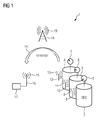
- FIG. 1 a switchgear 1 is shown schematically.
- Three filled with the protective gas SF 6 filled containers 2,3,4 - in this case gas-insulated high-voltage switchgear - each have an analog measuring device 5,6,7, which indicates the gas density.
- the arrows in the measuring devices 5, 6, 7 indicate the indication of the gas density on an analog scale.
- Each of the containers 2, 3, 4 has at its gas filling device an arrangement 8, 10, 12 according to the invention, which use the surrounding electromagnetic radiation 19 of a radiation source 18 - a TV transmitting mast - for generating energy.
- the arrangements 8,10,12 transmit the measured parameters of the gas, in this case the temperature and the gas pressure, via radio links 9, 11, 13, such as W-LAN, to an evaluation device 17.
- the digital transmission of the data is indicated by the arrow 14 and the signal 101101001.
- the evaluation device 17 has an antenna 16 for receiving and / or transmitting radio signals 15 and is set up to calculate the density of the gas from the measured parameters gas pressure and temperature. In this way it can be precisely determined over the course of time of several measurements at what rate a gas loss takes place within the container.
- the evaluation device 17, by means of its transmitting function in addition to the radiation source 18 or also instead of the radiation source 18, can provide electromagnetic radiation for the energy supply of the energy supply devices of the arrangements.
- the evaluation device 17 is arranged close to the individual containers in this example, but it could also be arranged anywhere in accordance with wider-reaching communication means such as an Internet connection anywhere.
- an existing container can be retrofitted to its usually existing Gasein spallvoriques with the inventive arrangement 8,10,12.
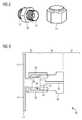
- FIG. 2 shows a known closure device 21 for a gas filling device 20 of a container, wherein the Gasein glycollvoriques 20 has a back 22 and a front side 23 with a valve. If the arrangement according to the invention is to be used instead of the closure device 21 shown to retrofit an existing container, the arrangement according to the invention must be suitable for use with the gas filling device 20.
- FIG. 3 an embodiment of a system 30 according to the invention is shown schematically.
- area 31 there is a tank which is filled with inert gas SF 6 .
- a conventional Gasein spallvoroplasty 20 is attached to the container.
- This has a base 34 with a bulge 35, in which a chamber 37 and a through hole 36 are located.
- Chamber 37 and through-hole 36 form a fluid-conducting connection with the container and therefore contain the gas.
- the chamber is open to the left.
- the assembly has a jacket 38 and a socket 39 with sealing means (black dots).
- sealing means black dots.
- the casing 38 surrounds the left part of the base 34 and the bushing 39 surrounds the bulge 35, so that the chamber 37 bears against the middle part 40. In this way, during operation of the system, the gas SF 6 is present at the central part of the arrangement.
- the middle part 40 of the arrangement has a gas pressure measuring device and a temperature measuring device with which gas pressure and temperature of the SF 6 can be determined.
- a computer device for controlling the arrangement can additionally be provided in the middle part and processing of the measured parameters and an energy storage can be provided.
- Adjoining the central part 40 is an outer part 43 which, on the one hand, has a power supply device 41 which is suitable for obtaining electrical energy from the surrounding electromagnetic radiation.
- the outer part 43 has a communication device 42 which is suitable for transmitting the measured parameters to an evaluation device.
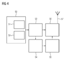
- FIG. 4 shows an embodiment of an inventive arrangement with a power supply device 50, which is adapted to gain electrical energy from the surrounding electromagnetic radiation.
- a first energy-generating device 51 is used for obtaining electrical energy from surrounding radio waves, such as TV signals and / or radio signals, and / or a second energy-generating device 52 for obtaining electrical energy from light.
- the electrical energy obtained is temporarily stored in an energy store 53 and, if necessary, eg periodically once a day, used to determine gas pressure and temperature by means of a measuring device 54 and to transmit it to a computer device 55.
- the computer device 55 processes the measured parameters and can calculate the density of the protective gas in the container on the basis of a calculation rule adapted to the inert gas SF 6 from the gas pressure and the temperature.
- the calculated density value and possibly the measured parameters are transmitted via a communication device 56 with antenna 57 for further processing by radio.
- the communication device 56 is likewise supplied by the energy store 53.
Landscapes
- Physics & Mathematics (AREA)
- General Physics & Mathematics (AREA)
- Health & Medical Sciences (AREA)
- Life Sciences & Earth Sciences (AREA)
- Chemical & Material Sciences (AREA)
- Analytical Chemistry (AREA)
- Biochemistry (AREA)
- General Health & Medical Sciences (AREA)
- Immunology (AREA)
- Pathology (AREA)
- Engineering & Computer Science (AREA)
- Computer Networks & Wireless Communication (AREA)
- Signal Processing (AREA)
- Filling Or Discharging Of Gas Storage Vessels (AREA)
- Arrangements For Transmission Of Measured Signals (AREA)
- Gas-Insulated Switchgears (AREA)
Abstract
Description
- Die Erfindung betrifft eine Anordnung nach dem Oberbegriff des Anspruch 1, ein System nach Anspruch 10 sowie ein entsprechendes Verfahren nach Anspruch 14.
- Elektrische Anlagen wie z.B. Hochspannungsschaltanlagen sind häufig mit einem Schutzgas wie z.B. Schwefelhexafluorid (SF6) isoliert. SF6 ist jedoch klimaschädlich und die Hersteller sowie die Betreiber der elektrischen Anlagen erhalten immer strengere Auflagen, SF6 Verluste in die Atmosphäre zu vermeiden. Neuere Richtlinien erfordern beispielsweise, dass weniger als 0.5 % des SF6 einer Anlage pro Jahr an die Umwelt abgegeben werden. Außerdem wird seit 2015 eine Überwachung des SF6-Drucks und der SF6-Gasdichte mindestens alle 6 Monate sowie das Führen eines Protokolls über den zeitlichen Verlauf des SF6-Drucks und der SF6-Gasdichte verlangt, wobei diese Regeln für alle Anlagen mit mehr als 22 kg des Schutzgases gelten. Dies schließt so gut wie alle Hochspannungsanlagen ein.
- Derzeit werden zur Überwachung der elektrischen Anlagen häufig analoge Gasdruck- oder Gasdichtemesseinrichtungen einsetzt, die an der Anlage angebracht werden und vor Ort durch einen Techniker abgelesen werden müssen. Fällt der Gasdruck oder die Gasdichte unter vorher festgelegte Schwellenwerte, wird ein Alarm ausgelöst und/oder die elektrische Anlage wird direkt abgeschaltet, um Fehler und Schäden an der Anlage zu vermeiden. Dies stellt ein Problem für die Zuverlässigkeit eines Energieverteilungsnetzes dar, weil der Ausfall einer elektrischen Anlage wegen Schutzgasverlusten nicht vorhergesagt werden kann - entweder die Schwellenwerte werden nicht unterschritten und die Anlage bleibt in Betrieb oder die Schwellenwerte werden unterschritten und es kommt zum Ausfall bzw. einer Abschaltung. Aus diesem Grund werden die eingangs erwähnten Protokolle gefordert, denn anhand dieser Aufzeichnungen lassen sich Gasverluste im zeitlichen Verlauf erkennen und anhand der Gasverlustrate die Notwendigkeit einer Wartung der elektrischen Anlage mit entsprechender Wiederherstellung des benötigten Schutzgasdrucks vorausberechnen.
- Dennoch ergeben sich auch bei einer periodischen Überwachung Probleme, weil viele ältere elektrische Anlagen derzeit über keine geeigneten Gasdruck- oder Gasdichtemesseinrichtungen und teuer nachgerüstet werden müssten. Außerdem sind Hochspannungsanlagen nicht immer leicht für Techniker zu erreichen und abzulesen, was die Überwachung dieser Anlagen erschwert und verteuert.
- Werden digitale Messeinrichtungen und Online-Überwachungssysteme eingesetzt, so müssen diese für ihre Energieversorgung mit Niederspannung versorgt werden. Dies ist oftmals jedoch nur technisch aufwändig mit einem Messwandler und damit teuer bereit zu stellen, insbesondere wenn alte Anlagen mit modernen Messeinrichtungen aufgerüstet werden sollen. Weiterhin müssen Datenverarbeitungseinrichtungen eingesetzt werden, die die Messdaten vor Ort auswerten und z.B. Gasdruck- und Gastemperaturwerte in Gasdichtewerte umrechnen.
- Ferner ist die Veröffentlichung "Ambient Backscatter: Wireless Communication Out of Thin Air" von Vincent Liu et al., University of Washington, erschienen bei SIGCOMM'13, August 12-16, 2013, Hong Kong, China, bekannt. Darin werden Geräte beschrieben, die miteinander kommunizieren können und dabei lediglich umgebende elektromagnetische Strahlung ("ambient radiofrequency signals") wie etwa Fernsehsignale verwenden zur Energieversorgung benötigen. Dabei wird eine Technik namens "Ambient Backscatter" eingesetzt, bei der die umgebende elektromagentische Strahlung von einem Gerät in modifizierter Form zurückgestreut wird, um Informationen wie z.B. Signale eines Berührungssensors zu übertragen. Weil die Geräte keine eigene elektromagnetische Strahlung erzeugen, sind sie besonders energiesparsam. Ein Prototyp erreicht Datenübertagungsraten von bis zu 1 kbps bei einer Entfernung von bis zu 2,5 Fuß zwischen den Geräten.
- Weiterhin ist der Website-Artikel "Battery-less wireless temperature sensors based on low power UHF RFID tags", 10. Juni 2013 von Mikel Choperena bekannt ("http://www.sensorsmag.com/product/development-platform-advances-battery-free-sensors-and"), der Sensoren der Firma Farsens beschreibt. Diese Sensoren nutzen RFID mit ultrahochfrequenten Signalen (ca. 900 MHz) und messen Temperatur, Druck, Luftfeuchtigkeit, etc. Als eine Einsatzmöglichkeit werden Sensoren für die Brandvermeidung bei elektrischen Schaltanlagen genannt. Die Reichweite der Datenkommunikation beträgt bis zu 1,5 m.
- Ein ähnliches System wird auch in der Bedienungsanleitung "STANDALONE SOFTWARE USER GUIDE; UG-STANDALONESW-V03" der Firma Farsens vom April 2014 beschrieben. Dabei wird eine Software beschrieben, mit der Sensordaten des Sensors "ANDY100" verarbeitet werden können. Ein solcher Sensor ist aus der Produktbroschüre "EPC C1G2 COMPLIANT BATTERYLESS SENSOR/ACTUATOR DEVELOPMENT PLATFORM POWERED BY ANDY100 PB-MEDUSA-V01" der Firma Farsens aus dem September 2014 bekannt.
- Es stellt sich an die Erfindung die Aufgabe, eine Anordnung für eine Überwachung von gasgefüllten Behältern bereit zu stellen, mit der automatisch und einfach eine Überwachung durchgeführt werden kann, ohne dass zusätzlicher Anschluss an ein Energieversorgungsnetz zur Energieversorgung der Anordnung bereit gestellt werden muss.
- Die Erfindung löst diese Aufgabe durch eine Anordnung gemäß Anspruch 1.
- Dies ist ein Vorteil, weil Kosten und Wartungsaufwand für das bereitstellen eines Anschlusses an ein Energieversorgungsnetz vermieden wird. Insbesondere ist es nicht erforderlich, mittels eines Messwandlers z.B. aus der an einer gasisolierten elektrischen Anlage anliegenden Hochspannung eine für die Spannungsversorgung der erfindungsgemäßen Anordnung geeignete Spannung zu erzeugen. Als Quellen der elektromagnetischen Strahlung bieten sich TV-Signale, Radiosignale oder Kommunikationsnetze wie 3G, 4G, etc. an, die in vielen Ländern nahezu flächendeckend verfügbar sind. Auch elektromagnetische Strahlung nahe Hochspannungsleitungen kann genutzt werden.
- Dabei ist es i.d.R. vorteilhaft, Messeinrichtungen mit vergleichsweise niedrigem Energiebedarf einzusetzen, wie sie beispielsweise aus den eingangs genannten RFID-Sensoren der Firma Farsens bekannt sind.
- Die Informationen über das Gas können die gemessenen Parameter und/oder andere Informationen umfassen, beispielsweise wenn direkt in der Anordnung eine Weiterverarbeitung der gemessenen Parameter erfolgt.
- In einer bevorzugten Ausführungsform der erfindungsgemäßen Anordnung wird eine zusätzliche Quelle von elektromagnetischer Strahlung eingesetzt, um mittels der Energieversorgungseinrichtung mehr elektrische Energie zu erzeugen. Es kann als zusätzliche Quelle z.B. eine WIFI, TV, Radio oder Lichtquelle eingesetzt werden. Dabei kann eine kontinuierliche Abstrahlung erfolgen, oder es können zeitlich kurze Strahlungsimpulse eingesetzt werden. Es ist ein Vorteil dieser kabellosen zusätzlichen Energieversorgung, dass am Einsatzort z.B. einer Schaltanlage mit mehreren Behältern, mit geringem Aufwand nur eine zusätzliche Quelle von elektromagnetischer Strahlung bereit gestellt werden muss, die ggf. ihrerseits durch Solarenergie versorgt werden kann, falls kein Energieversorgungsnetzanschluss bereit steht. Als zusätzliche Quelle kann auch die Auswerteeinrichtung eingerichtet sein, die dann nicht nur Messdaten empfängt, sondern auch Energie abstrahlt.
- In einer weiteren bevorzugten Ausführungsform der erfindungsgemäßen Anordnung umfasst die mindestens eine Messeinrichtung eine Gasdruckmesseinrichtung. Dies ist ein Vorteil, weil der Druck des Gases im Behälter Rückschlüsse auf die Dichtigkeit des Behälters gestattet.
- In einer weiteren bevorzugten Ausführungsform der erfindungsgemäßen Anordnung umfasst die mindestens eine Messeinrichtung eine Temperaturmesseinrichtung. Dies ist ein Vorteil, weil die Kenntnis der Temperatur in Verbindung mit dem Druck des Gases im Behälter Rückschlüsse auf die Dichte des Gases gestattet.
- In einer weiteren bevorzugten Ausführungsform der erfindungsgemäßen Anordnung ist die Kommunikationseinrichtung für die Herstellung einer Funkverbindung mit der Auswerteeinrichtung geeignet. Dies ist ein Vorteil, weil Funkverbindungen einfach, kostengünstig und flexibel einsetzbar sind.
- In einer bevorzugten weiteren bevorzugten Ausführungsform der erfindungsgemäßen Anordnung ist die Kommunikationseinrichtung für die Herstellung einer Funkverbindung mit benachbarten Anordnungen geeignet. Dies ist ein Vorteil, weil so z.B. bei mehreren zu überwachenden Anlagen ein Kommunikationsnetzwerk gebildet werden kann. Dabei kann gemeinsam für alle oder einen Teil der Teilnehmer des Netzwerks eine einzige Auswerteeinrichtung vorgesehen sein.
- In einer weiteren bevorzugten Ausführungsform der erfindungsgemäßen Anordnung ist die Energieversorgungseinrichtung geeignet, elektromagentische Strahlung im Radiofrequenzband und/oder im Frequenzband für TV-Signale und/oder im Frequenzband für Mobilfunk für die Energiegewinnung zu nutzen. Dies ist ein Vorteil, weil im Radiofrequenzband mit TV-Signalen und/oder Radiosignalen und/oder Mobilfunk wie etwa 3G oder 4G nahezu flächendeckend eine Energieversorgung gesichert ist.
- In einer weiteren bevorzugten Ausführungsform der erfindungsgemäßen Anordnung ist die Energieversorgungseinrichtung geeignet, Licht mittels Solarzellen für die Energiegewinnung zu nutzen. Dies ist ein Vorteil, weil die Energiegewinnung mittels Solarzellen lange erprobt und zuverlässig ist.
- In einer weiteren bevorzugten Ausführungsform der erfindungsgemäßen Anordnung ist ein Energiespeicher für das Zwischenspeichern der von der Energieversorgungseinrichtung erzeugten elektrischen Energie vorgesehen. Dies ist ein Vorteil, weil auf diese Weise auf eine sehr niedrige kontinuierliche Energieerzeugung eine wesentlich höhere Energiemenge erzeugen kann, mit der beispielsweise periodisch ein Mal pro Tag eine Messung von Parametern des Gases ermöglicht wird.
- In einer weiteren bevorzugten Ausführungsform der erfindungsgemäßen Anordnung ist die Auswerteeinrichtung geeignet, aus den gemessenen Parametern Gasdruck und Temperatur die Dichte des Gases zu berechnen. Dies ist ein Vorteil, weil so eine Weiterverarbeitung und Auswertung der gemessenen Parameter zentral bei der Auswerteeinrichtung erfolgen kann und in jeder einzelnen Anordnung keine eigene Rechenkapazität vorgesehen werden muss. Dies spart im Betrieb Energie, wodurch die Energieversorgungseinrichtung kleiner ausgelegt werden kann. Außerdem werden Kosten eingespart. Es erfolgt mit der Kommunikationseinrichtung eine Übertragung der gemessenen Parameter an die Auswerteeinrichtung.
- In einer weiteren bevorzugten Ausführungsform der erfindungsgemäßen Anordnung ist eine Rechnereinrichtung vorgesehen, die geeignet ist, aus den gemessenen Parametern Gasdruck und Temperatur die Dichte des Gases zu berechnen. Dies ist ein Vorteil, weil so eine Weiterverarbeitung und Auswertung der gemessenen Parameter lokal bei der Anordnung erfolgen kann. Es erfolgt mit der Kommunikationseinrichtung eine Übertragung der berechneten Gasdichte an die Auswerteeinrichtung. Dies ist ein Vorteil, weil so sämtliche benötigte Funktionalität zur Ermittlung der Gasdichte in der Anordnung vorgesehen ist und die Auswerteeinrichtung lediglich eine Schnittstelle zum Empfang der Gasdichte benötigt.
- In einer weiteren bevorzugten Ausführungsform der erfindungsgemäßen Anordnung ist die mindestens eine Messeinrichtung einer Anschlussvorrichtung zugeordnet, die zum Anschließen an einen Behälter geeignet ist. Dies ist ein Vorteil, weil dadurch keine zusätzliche Öffnung in einen bestehenden Behälter eingebracht werden muss, sondern z.B. eine Gaseinfüllvorrichtung einer gasiolierten Schaltanlage genutzt werden kann, um eine automatische Überwachung des Gases im Behälter umzusetzen.
- Ferner stellt sich an die Erfindung die Aufgabe, eine System für eine Überwachung von gasgefüllten Behältern bereit zu stellen, mit dem automatisch und einfach eine Überwachung durchgeführt werden kann, ohne dass zusätzlicher Anschluss an ein Energieversorgungsnetz zur Energieversorgung der Anordnung bereit gestellt werden muss.
- Die Erfindung löst diese Aufgabe durch ein System gemäß Anspruch 10. Bevorzugte und vorteilhafte Ausführungsformen ergeben sich aus den Unteransprüchen 11 bis 13. Dabei ergeben sich für das erfindungsgemäße System und seine Ausführungsformen jeweils sinngemäß die gleichen Vorteile wie eingangs für die erfindungsgemäße Anordnung geschildert.
- Ferner stellt sich an die Erfindung die Aufgabe, ein Verfahren für eine Überwachung von gasgefüllten Behältern bereit zu stellen, mit dem automatisch und einfach eine Überwachung durchgeführt werden kann, ohne dass zusätzlicher Anschluss an ein Energieversorgungsnetz zur Energieversorgung der Anordnung bereit gestellt werden muss.
- Die Erfindung löst diese Aufgabe durch ein Verfahren gemäß Anspruch 14. Eine bevorzugte und vorteilhafte Ausführungsform ergibt sich aus dem Unteranspruch 15. Dabei ergeben sich für das erfindungsgemäße Verfahren und seine Ausführungsformen jeweils sinngemäß die gleichen Vorteile wie eingangs für die erfindungsgemäße Anordnung geschildert.
- Zur besseren Erläuterung der Erfindung zeigen die
- Figur 1
- ein Anwendungsbeispiel des erfindungsgemäßen Systems und
- Figur 2
- eine bekannte Verschlusseinrichtung für eine Gaseinfüllvorrichtung eines Behälters und
- Figur 3
- ein Ausführungsbeispiel eines erfindungsgemäßen Systems und
- Figur 4
- ein Ausführungsbeispiel einer erfindungsgemäßen Anordnung.
- In der
Figur 1 ist eine Schaltanlage 1 schematisch dargestellt. Drei mit dem Schutzgas gefüllte SF6 gefüllte Behälter 2,3,4 - in diesem Fall gasisolierte Hochspannungsschaltanlagen - weisen jeweils eine analoge Messeinrichtung 5,6,7 auf, die die Gasdichte anzeigt. Dabei deuten die Pfeile in den Messeinrichtungen 5,6,7 die Anzeige der Gasdichte auf einer analogen Skala an. - Jeder der Behälter 2,3,4 weist an seiner Gaseinfüllvorrichtung eine erfindungsgemäße Anordnung 8,10,12 auf, die die umgebende elektromagnetische Strahlung 19 einer Strahlungsquelle 18 - ein TV-Sendemast - zur Energiegewinnung nutzen.
- Die Anordnungen 8,10,12 übermitteln die gemessenen Parameter des Gases, in diesem Fall die Temperatur und der Gasdruck, über Funkverbindungen 9,11,13 wie etwa W-LAN an eine Auswerteeinrichtung 17. Die digitale Übertragung der Daten ist angedeutet durch den Pfeil 14 und das Signal 101101001.
- Die Auswerteeinrichtung 17 weist eine Antenne 16 für Empfang und/oder Senden von Funksignalen 15 auf und ist eingerichtet, aus den gemessenen Parametern Gasdruck und Temperatur die Dichte des Gases zu berechnen. Damit kann über den zeitlichen Verlauf mehrerer Messungen genau festgestellt werden, mit welcher Rate ein Gasverlust innerhalb des Behälters erfolgt. Die Auswerteeinrichtung 17 kann mittels ihrer Sendefunktion zusätzlich zu der Strahlungsquelle 18 oder auch anstatt der Strahlungsquelle 18 elektromagentische Strahlung für die Energieversorgung der Energieversorgungseinrichtungen der Anordnungen bereit stellen.
- Die Auswerteeinrichtung 17 ist in diesem Beispiel nahe bei den einzelnen Behältern angeordnet, sie könnte aber bei entsprechend weiterreichenderen Kommunikationsmitteln wie etwa einer Internetverbindung auch an beliebiger Stelle weltweit angeordnet sein.
- Es ist ein Vorteil des erfindungsgemäßen Systems, dass an keinem der Behälter extra eine Stromversorgung bzw. ein Energienetzanschluss für die Anordnungen 8,10,12 eingerichtet werden muss.
- Vielmehr kann ein bestehender Behälter an seiner üblicherweise bereits vorhandenen Gaseinfüllvorrichtung mit der erfindungsgemäßen Anordnung 8,10,12 nachgerüstet werden.
- Die
Figur 2 zeigt eine bekannte Verschlusseinrichtung 21 für eine Gaseinfüllvorrichtung 20 eines Behälters, wobei die Gaseinfüllvorrichtung 20 eine Rückseite 22 und eine Vorderseite 23 mit einem Ventil aufweist. Soll die erfindungsgemäße Anordnung anstatt der gezeigten Verschlusseinrichtung 21 eingesetzt werden, um einen bestehenden Behälter nachzurüsten, muss die erfindungsgemäße Anordnung zur Verwendung mit der Gaseinfüllvorrichtung 20 geeignet sein. - In der
Figur 3 ist ein Ausführungsbeispiel eines erfindungsgemäßen Systems 30 schematisch dargestellt. Im Bereich 31 befindet sich ein Behälter, der mit dem Schutzgas SF6 befüllt ist. - Im Bereich 32 ist eine übliche Gaseinfüllvorrichtung 20 am Behälter angebracht. Diese weist einen Sockel 34 mit einer Ausbuchtung 35 auf, in der sich eine Kammer 37 und eine Durchgangsöffnung 36 befinden. Kammer 37 und Durchgangsöffnung 36 bilden eine fluidleitende Verbindung mit dem Behälter und enthalten daher das Gas. Die Kammer ist zur linken Seite hin offen.
- Im Bereich 33 ist eine erfindungsgemäße Anordnung gezeigt, die zur besseren Übersichtlichkeit noch nicht voll auf die Gaseinfüllvorrichtung 20 geschoben ist (in Pfeilrichtung). Die Anordnung weist einen Mantel 38 und eine Buchse 39 mit Dichtmitteln (schwarze Punkte) auf. Am Grund der Buchse 39 befindet sich ein Mittelteil 40.
- Ist die Anordnung komplett auf die Gaseinfüllvorrichtung 20 geschoben, so umgreift der Mantel 38 den linken Teil des Sockels 34 und die Buchse 39 umschließt die Ausbuchtung 35, so dass die Kammer 37 an dem Mittelteil 40 anliegt. Auf diese Weise liegt im Betrieb des Systems das Gas SF6 am Mittelteil der Anordnung vor.
- Der Mittelteil 40 der Anordnung weist eine Gasdruckmesseinrichtung und eine Temperaturmesseinrichtung auf, mit denen Gasdruck und Temperatur des SF6 bestimmt werden können.
- In einer Weiterbildung der Anordnung können zusätzlich im Mittelteil eine Rechnereinrichtung zur Steuerung der Anordnung und Verarbeitung der gemessenen Parameter sowie ein Energiespeicher vorgesehen sein.
- An den Mittelteil 40 grenzt ein Außenteil 43, das einerseits eine Energieversorgungseinrichtung 41 aufweist, die geeignet ist, aus der umgebenden elektromagnetischen Strahlung elektrische Energie zu gewinnen. Andererseits weist das Außenteil 43 eine Kommunikationseinrichtung 42 auf, die für eine Übermittlung der gemessenen Parameter an eine Auswerteeinrichtung geeignet ist.
- Die
Figur 4 zeigt ein Ausführungsbeispiel einer erfindungsgemäßen Anordnung mit einer Energieversorgungseinrichtung 50, die geeignet ist, aus der umgebenden elektromagnetischen Strahlung elektrische Energie zu gewinnen. Dabei kommt eine erste Energiegewinnungseinrichtung 51 zu Gewinnung von elektrischer Energie aus umgebenden Funkwellen wie z.B. TV-Signalen und/oder Radiosignalen und/oder eine zweite Energiegewinnungseinrichtung 52 zu Gewinnung von elektrischer Energie aus Licht zum Einsatz. - Die gewonnene elektrische Energie wird in einem Energiespeicher 53 zwischengespeichert und bei Bedarf, z.B. periodisch einmal pro Tag, verwendet, um mittels einer Messeinrichtung 54 Gasdruck und Temperatur zu bestimmen und an eine Rechnereinrichtung 55 zu übermitteln. Die Rechnereinrichtung 55 verarbeitet die gemessenen Parameter und kann anhand einer auf das Schutzgas SF6 abgestimmten Berechnungsvorschrift aus dem Gasdruck und der Temperatur die Dichte des Schutzgases im Behälter berechnen.
- Schließlich wird der berechnete Dichtewert und ggf. die gemessenen Parameter über eine Kommunikationseinrichtung 56 mit Antenne 57 zur weiteren Verarbeitung per Funk übertragen. Dabei wird die Kommunikationseinrichtung 56 ebenfalls durch den Energiespeicher 53 versorgt.
Claims (15)
- Anordnung für eine Überwachung von gasgefüllten Behältern, aufweisend:mindestens eine Messeinrichtung für das Messen mindestens eines Parameters des Gases im Behälter,eine Kommunikationseinrichtung, die für eine Übermittlung von Informationen über das Gas an eine Auswerteeinrichtung geeignet ist,eine Energieversorgungseinrichtung, die geeignet ist, aus der umgebenden elektromagnetischen Strahlung elektrische Energie zu gewinnen.
- Anordnung nach Anspruch 1, dadurch gekennzeichnet, dass die mindestens eine Messeinrichtung eine Gasdruckmesseinrichtung umfasst.
- Anordnung nach Anspruch 1 oder 2, dadurch gekennzeichnet, dass die mindestens eine Messeinrichtung eine Temperaturmesseinrichtung umfasst.
- Anordnung nach einem der vorhergehenden Ansprüche, dadurch gekennzeichnet, dass die Kommunikationseinrichtung für die Herstellung einer Funkverbindung mit der Auswerteeinrichtung geeignet ist.
- Anordnung nach einem der vorhergehenden Ansprüche, dadurch gekennzeichnet, dass die Energieversorgungseinrichtung geeignet ist, elektromagentische Strahlung im Radiofrequenzband und/oder im Frequenzband für TV-Signale und/oder im Frequenzband für Mobilfunk für die Energiegewinnung zu nutzen.
- Anordnung nach Anspruch 4 oder 5, dadurch gekennzeichnet, dass die Energieversorgungseinrichtung geeignet ist, Licht mittels Solarzellen für die Energiegewinnung zu nutzen.
- Anordnung nach einem der vorhergehenden Ansprüche, dadurch gekennzeichnet, dass ein Energiespeicher für das Zwischenspeichern der von der Energieversorgungseinrichtung erzeugten elektrischen Energie vorgesehen ist.
- Anordnung nach einem der vorhergehenden Ansprüche, dadurch gekennzeichnet, dass die Auswerteeinrichtung geeignet ist, aus den gemessenen Parametern Gasdruck und Temperatur die Dichte des Gases zu berechnen.
- Anordnung nach einem der vorhergehenden Ansprüche, dadurch gekennzeichnet, dass die mindestens eine Messeinrichtung einer Anschlussvorrichtung zugeordnet ist, die zum Anschließen an einen Behälter geeignet ist.
- System für eine Überwachung von gasgefüllten Behältern, aufweisend:eine Anordnung nach einem der vorhergehenden Ansprüche und einen gasgefüllten Behälter.
- System nach Anspruch 10, dadurch gekennzeichnet, dass der Behälter eine elektrische Anlage ist, die mit einem Schutzgas gefüllt ist.
- System nach Anspruch 11, dadurch gekennzeichnet, dass das Schutzgas Schwefelhexafluorid umfasst.
- System nach einem der Ansprüche 10 bis 12, dadurch gekennzeichnet, dass die Anordnung zur Nachrüstung eines Behälters an dessen bestehender Gaseinfüllvorrichtung geeignet ist.
- Verfahren für eine Überwachung von gasgefüllten Behältern, bei dem
aus der einen gasgefüllten Behälter umgebenden elektromagnetischen Strahlung elektrische Energie zur Energieversorgung mindestens einer Messeinrichtung und einer Kommunikationseinrichtung gewonnen wird, und
mittels der mindestens Messeinrichtung mindestens ein Parameter des Gases im Behälter gemessen wird, und
Informationen über das Gas mittels einer Kommunikationseinrichtung an eine Auswerteeinrichtung übermittelt werden. - Verfahren nach Anspruch 14, dadurch gekennzeichnet, dass mittels der mindestens einen Messeinrichtung die Parameter Gasdruck und Temperatur gemessen werden, und
aus den gemessenen Parametern die Dichte des Gases berechnet wird.
Applications Claiming Priority (1)
| Application Number | Priority Date | Filing Date | Title |
|---|---|---|---|
| DE102015206873.0A DE102015206873A1 (de) | 2015-04-16 | 2015-04-16 | Anordnung, System und Verfahren für eine Überwachung von gasgefüllten Behältern |
Publications (2)
| Publication Number | Publication Date |
|---|---|
| EP3081907A1 true EP3081907A1 (de) | 2016-10-19 |
| EP3081907B1 EP3081907B1 (de) | 2020-07-29 |
Family
ID=56014778
Family Applications (1)
| Application Number | Title | Priority Date | Filing Date |
|---|---|---|---|
| EP16163969.5A Active EP3081907B1 (de) | 2015-04-16 | 2016-04-06 | Anordnung, system und verfahren für eine überwachung von gasgefüllten behältern |
Country Status (4)
| Country | Link |
|---|---|
| US (1) | US10670503B2 (de) |
| EP (1) | EP3081907B1 (de) |
| DE (1) | DE102015206873A1 (de) |
| ES (1) | ES2825717T3 (de) |
Cited By (1)
| Publication number | Priority date | Publication date | Assignee | Title |
|---|---|---|---|---|
| CN106596329A (zh) * | 2016-12-19 | 2017-04-26 | 华能国际电力股份有限公司玉环电厂 | 基于就地显示仪的gis六氟化硫密度在线监测系统 |
Families Citing this family (4)
| Publication number | Priority date | Publication date | Assignee | Title |
|---|---|---|---|---|
| DE102018209767A1 (de) * | 2018-06-18 | 2019-12-19 | Siemens Aktiengesellschaft | Verfahren, Anordnung und Computerprogrammprodukt zum Überwachen von Verbrauchsmitteln über mehrere Nutzungszyklen |
| CN109725234A (zh) * | 2019-01-24 | 2019-05-07 | 山东欣巽联信息科技有限公司 | 一种基于物联网和审慎原则的开闭所实时健康状态评估方法 |
| CN111189856B (zh) * | 2020-03-15 | 2021-02-26 | 太原理工大学 | 一种采用环境反向散射技术的土壤水分检测方法 |
| DE102021200290A1 (de) | 2021-01-14 | 2022-07-14 | Siemens Energy Global GmbH & Co. KG | Isolierfluidüberwachungsblock sowie Montageverfahren |
Citations (5)
| Publication number | Priority date | Publication date | Assignee | Title |
|---|---|---|---|---|
| DE19703854A1 (de) * | 1997-02-03 | 1998-08-06 | Lange Gmbh Dr Bruno | Multifunktionales Labormeßgerät |
| US20030107483A1 (en) * | 2000-05-30 | 2003-06-12 | Shiro Kano | Sensor device, setting device reading device, and article administration system |
| EP1238246B1 (de) * | 1999-12-17 | 2004-03-03 | J & M Holding B.V. | Gerät und system zur messung eines parameters in einem geschlossenen raum |
| DE102007017632A1 (de) * | 2007-04-13 | 2008-10-16 | Sentec Elektronik Gmbh | Sensoranordnung |
| WO2012140310A1 (en) * | 2011-04-15 | 2012-10-18 | Upm Rfid Oy | Method and apparatus for monitoring an environmental variable |
Family Cites Families (12)
| Publication number | Priority date | Publication date | Assignee | Title |
|---|---|---|---|---|
| DE9316327U1 (de) | 1993-10-26 | 1994-11-03 | Hamburger Gaswerke GmbH, 20097 Hamburg | Druckerfassungs- und Speicherungsmodul für Gasdruckreglerstationen |
| DE19523939C2 (de) | 1995-07-05 | 1999-05-20 | Ernst Dr Med Schaefer | Anlage zur Speicherung und Nutzbarmachung von Solar-, Wind- und/oder Wasserkraftenergie |
| JP2000504553A (ja) * | 1996-01-31 | 2000-04-11 | シーメンス アクチエンゲゼルシヤフト | 閉鎖形設備 |
| FR2787571B1 (fr) * | 1998-12-18 | 2001-01-12 | Alstom | Methode de mesure de la densite d'un gaz dielectrique dans une ligne blindee enterree |
| US7086593B2 (en) * | 2003-04-30 | 2006-08-08 | The United States Of America As Represented By The Administrator Of The National Aeronautics And Space Administration | Magnetic field response measurement acquisition system |
| US20050008904A1 (en) | 2003-07-11 | 2005-01-13 | Suppes Galen J. | Regenerative fuel cell technology |
| US8437976B2 (en) * | 2004-07-29 | 2013-05-07 | Kulite Semiconductor Products, Inc. | Gas density transducer with a microprocessor executing an algorithm solving Van Der Waal's equation |
| JP2007170555A (ja) | 2005-12-22 | 2007-07-05 | Yazaki Corp | 液化ガス供給装置 |
| JP4957089B2 (ja) * | 2006-06-13 | 2012-06-20 | 富士ゼロックス株式会社 | センサ |
| US8380463B2 (en) * | 2006-11-16 | 2013-02-19 | Endress + Hauser Gmbh + Co. Kg | Apparatus having a modularly constructed, measuring transducer circuit |
| FR2915821B1 (fr) | 2007-05-03 | 2009-11-20 | Air Liquide | Procede de traitement de donnees relatives a une bouteille de fluide sous pression |
| US9239254B1 (en) * | 2012-04-19 | 2016-01-19 | Maxim Integrated Products, Inc. | Ambient temperature measurement |
-
2015
- 2015-04-16 DE DE102015206873.0A patent/DE102015206873A1/de not_active Withdrawn
-
2016
- 2016-04-06 ES ES16163969T patent/ES2825717T3/es active Active
- 2016-04-06 EP EP16163969.5A patent/EP3081907B1/de active Active
- 2016-04-18 US US15/131,225 patent/US10670503B2/en active Active
Patent Citations (5)
| Publication number | Priority date | Publication date | Assignee | Title |
|---|---|---|---|---|
| DE19703854A1 (de) * | 1997-02-03 | 1998-08-06 | Lange Gmbh Dr Bruno | Multifunktionales Labormeßgerät |
| EP1238246B1 (de) * | 1999-12-17 | 2004-03-03 | J & M Holding B.V. | Gerät und system zur messung eines parameters in einem geschlossenen raum |
| US20030107483A1 (en) * | 2000-05-30 | 2003-06-12 | Shiro Kano | Sensor device, setting device reading device, and article administration system |
| DE102007017632A1 (de) * | 2007-04-13 | 2008-10-16 | Sentec Elektronik Gmbh | Sensoranordnung |
| WO2012140310A1 (en) * | 2011-04-15 | 2012-10-18 | Upm Rfid Oy | Method and apparatus for monitoring an environmental variable |
Non-Patent Citations (4)
| Title |
|---|
| BATTERY-LESS WIRELESS TEMPERATURE SENSORS BASED ON LOW POWER UHF RFID TAGS, 10 June 2013 (2013-06-10), Retrieved from the Internet <URL:http://www.sensorsmag.com/product/development-platformadvances-battery-free-sensors-and> |
| EPC C1G2 COMPLIANT BATTERYLESS SENSOR/ACTUATOR DEVELOPMENT PLATFORM POWERED BY ANDY100 PB-MEDUSA-V01, September 2014 (2014-09-01) |
| STANDALONE SOFTWARE USER GUIDE; UG-STANDALONESW-V03, April 2014 (2014-04-01) |
| VINCENT LIU ET AL.: "Ambient Backscatter: Wireless Communication Out of Thin Air", SIGCOMM'13, 12 August 2013 (2013-08-12) |
Cited By (1)
| Publication number | Priority date | Publication date | Assignee | Title |
|---|---|---|---|---|
| CN106596329A (zh) * | 2016-12-19 | 2017-04-26 | 华能国际电力股份有限公司玉环电厂 | 基于就地显示仪的gis六氟化硫密度在线监测系统 |
Also Published As
| Publication number | Publication date |
|---|---|
| ES2825717T3 (es) | 2021-05-17 |
| DE102015206873A1 (de) | 2016-10-20 |
| US10670503B2 (en) | 2020-06-02 |
| US20160305862A1 (en) | 2016-10-20 |
| EP3081907B1 (de) | 2020-07-29 |
Similar Documents
| Publication | Publication Date | Title |
|---|---|---|
| EP3081907B1 (de) | Anordnung, system und verfahren für eine überwachung von gasgefüllten behältern | |
| EP3139188B1 (de) | Verfahren und vorrichtung zur isolationsfehlersuche mit adaptiver prüfstrom-ermittlung | |
| AT501758A4 (de) | Verfahren zur ortung von leckagen in rohren | |
| WO2019161849A1 (de) | Verfahren zum bestimmen eines betriebszustands eines elektrischen betriebsmittels und anordnung | |
| EP2947426B1 (de) | Verfahren zum betreiben einer messstelle | |
| WO2020052892A1 (de) | MEßGERÄTE-SYSTEM SOWIE DAMIT GEBILDETE MEßANORDNUNG | |
| EP3928413A1 (de) | Verfahren und system zum überwachen des betriebszustandes eines energieversorgungsnetzes | |
| WO2018091206A1 (de) | Verfahren zur bestimmung einer restbetriebs-zeitdauer einer detektor-einheit | |
| WO2024061486A1 (de) | Messdatenverarbeitungsvorrichtung für öltransformatoren und messsystem | |
| DE112013002386T5 (de) | Einrichtung zum Überprüfen von Datenübertragungen auf zweidrahtigen, kombiniert verbundenen Energie- und Datennetzsystemen für eine Automatisierung | |
| WO2025228656A1 (de) | Verfahren zum bereitstellen von lebensdauerdaten | |
| DE102020121949B4 (de) | Abgrenzeinheit, Pipelinesystem sowie Verfahren zum Betreiben eines Pipelinesystems | |
| EP3707480B1 (de) | Verfahren zur ortsaufgelösten bestimmung von zumindest einer physikalischen oder chemischen prozessgrösse | |
| DE102016124796A1 (de) | Sensorkopfmodul zur kontinuierlichen automatisierten Datenerfassung | |
| EP3716437A1 (de) | Verfahren und system zum überwachen des betriebszustandes von hochspannungsgeräten eines energieversorgungsnetzes | |
| DE102014009354A1 (de) | Verfahren und Vorrichtung zur Fehleranalyse einer Messeinrichtung | |
| DE102014112019B4 (de) | Sensoreinheit zur Temperaturüberwachung sowie zur Temperaturkompensation eines Ultraschallsensors sowie eine Anordnung enthaltend eine Sensoreinheit und einen Ultraschallsensor | |
| DE102008005672B4 (de) | Vorrichtung und Verfahren zum Erfassen von Strukturveränderungen eines Bauteils | |
| DE102017113633A1 (de) | Verfahren zur Überwachung eines elektrisch leitfähigen und durch kathodischen Korrosionsschutz geschützten Objekts | |
| DE112020006177T5 (de) | Verfahren, Vorrichtung und Anordnung zur Überwachung von elektrischen Wechselstromgeräten | |
| AT528102B1 (de) | System und Verfahren zum Überwachen von Teilentladungsaktivität | |
| DE102018110552A1 (de) | Verfahren zum Reduzieren einer zu übertragenden Datenmenge eines Feldgeräts | |
| DE102024204770A1 (de) | Gasisolierte Schaltanlage | |
| DE202013006449U1 (de) | Aufzeichnungseinrichtung | |
| DE102017201255A1 (de) | Vorrichtung und Anordnung für eine Zustandsüberwachung einer elektrischen Hoch- oder Mittelspannungsleitung |
Legal Events
| Date | Code | Title | Description |
|---|---|---|---|
| PUAI | Public reference made under article 153(3) epc to a published international application that has entered the european phase |
Free format text: ORIGINAL CODE: 0009012 |
|
| AK | Designated contracting states |
Kind code of ref document: A1 Designated state(s): AL AT BE BG CH CY CZ DE DK EE ES FI FR GB GR HR HU IE IS IT LI LT LU LV MC MK MT NL NO PL PT RO RS SE SI SK SM TR |
|
| AX | Request for extension of the european patent |
Extension state: BA ME |
|
| STAA | Information on the status of an ep patent application or granted ep patent |
Free format text: STATUS: REQUEST FOR EXAMINATION WAS MADE |
|
| 17P | Request for examination filed |
Effective date: 20170418 |
|
| RBV | Designated contracting states (corrected) |
Designated state(s): AL AT BE BG CH CY CZ DE DK EE ES FI FR GB GR HR HU IE IS IT LI LT LU LV MC MK MT NL NO PL PT RO RS SE SI SK SM TR |
|
| RAP1 | Party data changed (applicant data changed or rights of an application transferred) |
Owner name: SIEMENS AKTIENGESELLSCHAFT |
|
| STAA | Information on the status of an ep patent application or granted ep patent |
Free format text: STATUS: EXAMINATION IS IN PROGRESS |
|
| 17Q | First examination report despatched |
Effective date: 20180815 |
|
| GRAP | Despatch of communication of intention to grant a patent |
Free format text: ORIGINAL CODE: EPIDOSNIGR1 |
|
| STAA | Information on the status of an ep patent application or granted ep patent |
Free format text: STATUS: GRANT OF PATENT IS INTENDED |
|
| INTG | Intention to grant announced |
Effective date: 20200309 |
|
| GRAS | Grant fee paid |
Free format text: ORIGINAL CODE: EPIDOSNIGR3 |
|
| GRAA | (expected) grant |
Free format text: ORIGINAL CODE: 0009210 |
|
| STAA | Information on the status of an ep patent application or granted ep patent |
Free format text: STATUS: THE PATENT HAS BEEN GRANTED |
|
| AK | Designated contracting states |
Kind code of ref document: B1 Designated state(s): AL AT BE BG CH CY CZ DE DK EE ES FI FR GB GR HR HU IE IS IT LI LT LU LV MC MK MT NL NO PL PT RO RS SE SI SK SM TR |
|
| REG | Reference to a national code |
Ref country code: CH Ref legal event code: EP |
|
| REG | Reference to a national code |
Ref country code: AT Ref legal event code: REF Ref document number: 1296323 Country of ref document: AT Kind code of ref document: T Effective date: 20200815 |
|
| REG | Reference to a national code |
Ref country code: IE Ref legal event code: FG4D Free format text: LANGUAGE OF EP DOCUMENT: GERMAN |
|
| REG | Reference to a national code |
Ref country code: DE Ref legal event code: R096 Ref document number: 502016010621 Country of ref document: DE |
|
| REG | Reference to a national code |
Ref country code: CH Ref legal event code: NV Representative=s name: SIEMENS SCHWEIZ AG, CH |
|
| REG | Reference to a national code |
Ref country code: FI Ref legal event code: FGE |
|
| REG | Reference to a national code |
Ref country code: NL Ref legal event code: FP |
|
| REG | Reference to a national code |
Ref country code: SE Ref legal event code: TRGR |
|
| REG | Reference to a national code |
Ref country code: LT Ref legal event code: MG4D |
|
| REG | Reference to a national code |
Ref country code: DE Ref legal event code: R081 Ref document number: 502016010621 Country of ref document: DE Owner name: SIEMENS ENERGY GLOBAL GMBH & CO. KG, DE Free format text: FORMER OWNER: SIEMENS AKTIENGESELLSCHAFT, 80333 MUENCHEN, DE |
|
| RAP2 | Party data changed (patent owner data changed or rights of a patent transferred) |
Owner name: SIEMENS ENERGY GLOBAL GMBH & CO. KG |
|
| PG25 | Lapsed in a contracting state [announced via postgrant information from national office to epo] |
Ref country code: GR Free format text: LAPSE BECAUSE OF FAILURE TO SUBMIT A TRANSLATION OF THE DESCRIPTION OR TO PAY THE FEE WITHIN THE PRESCRIBED TIME-LIMIT Effective date: 20201030 Ref country code: LT Free format text: LAPSE BECAUSE OF FAILURE TO SUBMIT A TRANSLATION OF THE DESCRIPTION OR TO PAY THE FEE WITHIN THE PRESCRIBED TIME-LIMIT Effective date: 20200729 Ref country code: HR Free format text: LAPSE BECAUSE OF FAILURE TO SUBMIT A TRANSLATION OF THE DESCRIPTION OR TO PAY THE FEE WITHIN THE PRESCRIBED TIME-LIMIT Effective date: 20200729 Ref country code: PT Free format text: LAPSE BECAUSE OF FAILURE TO SUBMIT A TRANSLATION OF THE DESCRIPTION OR TO PAY THE FEE WITHIN THE PRESCRIBED TIME-LIMIT Effective date: 20201130 Ref country code: NO Free format text: LAPSE BECAUSE OF FAILURE TO SUBMIT A TRANSLATION OF THE DESCRIPTION OR TO PAY THE FEE WITHIN THE PRESCRIBED TIME-LIMIT Effective date: 20201029 Ref country code: BG Free format text: LAPSE BECAUSE OF FAILURE TO SUBMIT A TRANSLATION OF THE DESCRIPTION OR TO PAY THE FEE WITHIN THE PRESCRIBED TIME-LIMIT Effective date: 20201029 |
|
| PG25 | Lapsed in a contracting state [announced via postgrant information from national office to epo] |
Ref country code: PL Free format text: LAPSE BECAUSE OF FAILURE TO SUBMIT A TRANSLATION OF THE DESCRIPTION OR TO PAY THE FEE WITHIN THE PRESCRIBED TIME-LIMIT Effective date: 20200729 Ref country code: LV Free format text: LAPSE BECAUSE OF FAILURE TO SUBMIT A TRANSLATION OF THE DESCRIPTION OR TO PAY THE FEE WITHIN THE PRESCRIBED TIME-LIMIT Effective date: 20200729 Ref country code: RS Free format text: LAPSE BECAUSE OF FAILURE TO SUBMIT A TRANSLATION OF THE DESCRIPTION OR TO PAY THE FEE WITHIN THE PRESCRIBED TIME-LIMIT Effective date: 20200729 Ref country code: IS Free format text: LAPSE BECAUSE OF FAILURE TO SUBMIT A TRANSLATION OF THE DESCRIPTION OR TO PAY THE FEE WITHIN THE PRESCRIBED TIME-LIMIT Effective date: 20201129 |
|
| PG25 | Lapsed in a contracting state [announced via postgrant information from national office to epo] |
Ref country code: DK Free format text: LAPSE BECAUSE OF FAILURE TO SUBMIT A TRANSLATION OF THE DESCRIPTION OR TO PAY THE FEE WITHIN THE PRESCRIBED TIME-LIMIT Effective date: 20200729 Ref country code: CZ Free format text: LAPSE BECAUSE OF FAILURE TO SUBMIT A TRANSLATION OF THE DESCRIPTION OR TO PAY THE FEE WITHIN THE PRESCRIBED TIME-LIMIT Effective date: 20200729 Ref country code: RO Free format text: LAPSE BECAUSE OF FAILURE TO SUBMIT A TRANSLATION OF THE DESCRIPTION OR TO PAY THE FEE WITHIN THE PRESCRIBED TIME-LIMIT Effective date: 20200729 Ref country code: SM Free format text: LAPSE BECAUSE OF FAILURE TO SUBMIT A TRANSLATION OF THE DESCRIPTION OR TO PAY THE FEE WITHIN THE PRESCRIBED TIME-LIMIT Effective date: 20200729 Ref country code: EE Free format text: LAPSE BECAUSE OF FAILURE TO SUBMIT A TRANSLATION OF THE DESCRIPTION OR TO PAY THE FEE WITHIN THE PRESCRIBED TIME-LIMIT Effective date: 20200729 |
|
| REG | Reference to a national code |
Ref country code: DE Ref legal event code: R097 Ref document number: 502016010621 Country of ref document: DE |
|
| REG | Reference to a national code |
Ref country code: ES Ref legal event code: FG2A Ref document number: 2825717 Country of ref document: ES Kind code of ref document: T3 Effective date: 20210517 |
|
| PG25 | Lapsed in a contracting state [announced via postgrant information from national office to epo] |
Ref country code: AL Free format text: LAPSE BECAUSE OF FAILURE TO SUBMIT A TRANSLATION OF THE DESCRIPTION OR TO PAY THE FEE WITHIN THE PRESCRIBED TIME-LIMIT Effective date: 20200729 |
|
| PLBE | No opposition filed within time limit |
Free format text: ORIGINAL CODE: 0009261 |
|
| STAA | Information on the status of an ep patent application or granted ep patent |
Free format text: STATUS: NO OPPOSITION FILED WITHIN TIME LIMIT |
|
| PG25 | Lapsed in a contracting state [announced via postgrant information from national office to epo] |
Ref country code: SK Free format text: LAPSE BECAUSE OF FAILURE TO SUBMIT A TRANSLATION OF THE DESCRIPTION OR TO PAY THE FEE WITHIN THE PRESCRIBED TIME-LIMIT Effective date: 20200729 |
|
| 26N | No opposition filed |
Effective date: 20210430 |
|
| PG25 | Lapsed in a contracting state [announced via postgrant information from national office to epo] |
Ref country code: SI Free format text: LAPSE BECAUSE OF FAILURE TO SUBMIT A TRANSLATION OF THE DESCRIPTION OR TO PAY THE FEE WITHIN THE PRESCRIBED TIME-LIMIT Effective date: 20200729 |
|
| PGFP | Annual fee paid to national office [announced via postgrant information from national office to epo] |
Ref country code: BE Payment date: 20210420 Year of fee payment: 6 |
|
| PG25 | Lapsed in a contracting state [announced via postgrant information from national office to epo] |
Ref country code: MC Free format text: LAPSE BECAUSE OF FAILURE TO SUBMIT A TRANSLATION OF THE DESCRIPTION OR TO PAY THE FEE WITHIN THE PRESCRIBED TIME-LIMIT Effective date: 20200729 |
|
| PGFP | Annual fee paid to national office [announced via postgrant information from national office to epo] |
Ref country code: ES Payment date: 20210723 Year of fee payment: 6 |
|
| REG | Reference to a national code |
Ref country code: GB Ref legal event code: 732E Free format text: REGISTERED BETWEEN 20211202 AND 20211209 |
|
| PG25 | Lapsed in a contracting state [announced via postgrant information from national office to epo] |
Ref country code: LU Free format text: LAPSE BECAUSE OF NON-PAYMENT OF DUE FEES Effective date: 20210406 |
|
| PG25 | Lapsed in a contracting state [announced via postgrant information from national office to epo] |
Ref country code: IE Free format text: LAPSE BECAUSE OF NON-PAYMENT OF DUE FEES Effective date: 20210406 |
|
| PG25 | Lapsed in a contracting state [announced via postgrant information from national office to epo] |
Ref country code: IS Free format text: LAPSE BECAUSE OF FAILURE TO SUBMIT A TRANSLATION OF THE DESCRIPTION OR TO PAY THE FEE WITHIN THE PRESCRIBED TIME-LIMIT Effective date: 20201129 |
|
| REG | Reference to a national code |
Ref country code: AT Ref legal event code: PC Ref document number: 1296323 Country of ref document: AT Kind code of ref document: T Owner name: SIEMENS ENERGY GLOBAL GMBH & CO. KG, DE Effective date: 20221018 |
|
| REG | Reference to a national code |
Ref country code: BE Ref legal event code: MM Effective date: 20220430 |
|
| REG | Reference to a national code |
Ref country code: NL Ref legal event code: PD Owner name: SIEMENS ENERGY GLOBAL GMBH & CO. KG; DE Free format text: DETAILS ASSIGNMENT: CHANGE OF OWNER(S), ASSIGNMENT; FORMER OWNER NAME: SIEMENS AKTIENGESELLSCHAFT Effective date: 20230125 |
|
| PG25 | Lapsed in a contracting state [announced via postgrant information from national office to epo] |
Ref country code: BE Free format text: LAPSE BECAUSE OF NON-PAYMENT OF DUE FEES Effective date: 20220430 |
|
| REG | Reference to a national code |
Ref country code: ES Ref legal event code: FD2A Effective date: 20230526 |
|
| PG25 | Lapsed in a contracting state [announced via postgrant information from national office to epo] |
Ref country code: HU Free format text: LAPSE BECAUSE OF FAILURE TO SUBMIT A TRANSLATION OF THE DESCRIPTION OR TO PAY THE FEE WITHIN THE PRESCRIBED TIME-LIMIT; INVALID AB INITIO Effective date: 20160406 |
|
| PG25 | Lapsed in a contracting state [announced via postgrant information from national office to epo] |
Ref country code: CY Free format text: LAPSE BECAUSE OF FAILURE TO SUBMIT A TRANSLATION OF THE DESCRIPTION OR TO PAY THE FEE WITHIN THE PRESCRIBED TIME-LIMIT Effective date: 20200729 |
|
| PG25 | Lapsed in a contracting state [announced via postgrant information from national office to epo] |
Ref country code: ES Free format text: LAPSE BECAUSE OF NON-PAYMENT OF DUE FEES Effective date: 20220407 |
|
| PG25 | Lapsed in a contracting state [announced via postgrant information from national office to epo] |
Ref country code: MK Free format text: LAPSE BECAUSE OF FAILURE TO SUBMIT A TRANSLATION OF THE DESCRIPTION OR TO PAY THE FEE WITHIN THE PRESCRIBED TIME-LIMIT Effective date: 20200729 |
|
| PG25 | Lapsed in a contracting state [announced via postgrant information from national office to epo] |
Ref country code: TR Free format text: LAPSE BECAUSE OF FAILURE TO SUBMIT A TRANSLATION OF THE DESCRIPTION OR TO PAY THE FEE WITHIN THE PRESCRIBED TIME-LIMIT Effective date: 20200729 |
|
| PG25 | Lapsed in a contracting state [announced via postgrant information from national office to epo] |
Ref country code: MT Free format text: LAPSE BECAUSE OF FAILURE TO SUBMIT A TRANSLATION OF THE DESCRIPTION OR TO PAY THE FEE WITHIN THE PRESCRIBED TIME-LIMIT Effective date: 20200729 |
|
| PGFP | Annual fee paid to national office [announced via postgrant information from national office to epo] |
Ref country code: NL Payment date: 20250424 Year of fee payment: 10 |
|
| PGFP | Annual fee paid to national office [announced via postgrant information from national office to epo] |
Ref country code: FI Payment date: 20250424 Year of fee payment: 10 |
|
| PGFP | Annual fee paid to national office [announced via postgrant information from national office to epo] |
Ref country code: DE Payment date: 20250428 Year of fee payment: 10 |
|
| PGFP | Annual fee paid to national office [announced via postgrant information from national office to epo] |
Ref country code: IT Payment date: 20250422 Year of fee payment: 10 |
|
| PGFP | Annual fee paid to national office [announced via postgrant information from national office to epo] |
Ref country code: FR Payment date: 20250424 Year of fee payment: 10 |
|
| PGFP | Annual fee paid to national office [announced via postgrant information from national office to epo] |
Ref country code: CH Payment date: 20250501 Year of fee payment: 10 |
|
| PGFP | Annual fee paid to national office [announced via postgrant information from national office to epo] |
Ref country code: AT Payment date: 20250417 Year of fee payment: 10 |
|
| PGFP | Annual fee paid to national office [announced via postgrant information from national office to epo] |
Ref country code: SE Payment date: 20250424 Year of fee payment: 10 |
|
| PGFP | Annual fee paid to national office [announced via postgrant information from national office to epo] |
Ref country code: GB Payment date: 20260323 Year of fee payment: 11 |