EP3081895A1 - Multiple turret dircm system and related method of operation - Google Patents
Multiple turret dircm system and related method of operation Download PDFInfo
- Publication number
- EP3081895A1 EP3081895A1 EP16165697.0A EP16165697A EP3081895A1 EP 3081895 A1 EP3081895 A1 EP 3081895A1 EP 16165697 A EP16165697 A EP 16165697A EP 3081895 A1 EP3081895 A1 EP 3081895A1
- Authority
- EP
- European Patent Office
- Prior art keywords
- missile
- tracking
- jamming
- region
- subsystem
- Prior art date
- Legal status (The legal status is an assumption and is not a legal conclusion. Google has not performed a legal analysis and makes no representation as to the accuracy of the status listed.)
- Granted
Links
Images

Classifications
-
- F—MECHANICAL ENGINEERING; LIGHTING; HEATING; WEAPONS; BLASTING
- F41—WEAPONS
- F41H—ARMOUR; ARMOURED TURRETS; ARMOURED OR ARMED VEHICLES; MEANS OF ATTACK OR DEFENCE, e.g. CAMOUFLAGE, IN GENERAL
- F41H13/00—Means of attack or defence not otherwise provided for
- F41H13/0043—Directed energy weapons, i.e. devices that direct a beam of high energy content toward a target for incapacitating or destroying the target
- F41H13/005—Directed energy weapons, i.e. devices that direct a beam of high energy content toward a target for incapacitating or destroying the target the high-energy beam being a laser beam
- F41H13/0056—Directed energy weapons, i.e. devices that direct a beam of high energy content toward a target for incapacitating or destroying the target the high-energy beam being a laser beam for blinding or dazzling, i.e. by overstimulating the opponent's eyes or the enemy's sensor equipment
-
- F—MECHANICAL ENGINEERING; LIGHTING; HEATING; WEAPONS; BLASTING
- F41—WEAPONS
- F41G—WEAPON SIGHTS; AIMING
- F41G7/00—Direction control systems for self-propelled missiles
- F41G7/20—Direction control systems for self-propelled missiles based on continuous observation of target position
- F41G7/22—Homing guidance systems
- F41G7/224—Deceiving or protecting means
-
- F—MECHANICAL ENGINEERING; LIGHTING; HEATING; WEAPONS; BLASTING
- F41—WEAPONS
- F41H—ARMOUR; ARMOURED TURRETS; ARMOURED OR ARMED VEHICLES; MEANS OF ATTACK OR DEFENCE, e.g. CAMOUFLAGE, IN GENERAL
- F41H13/00—Means of attack or defence not otherwise provided for
- F41H13/0043—Directed energy weapons, i.e. devices that direct a beam of high energy content toward a target for incapacitating or destroying the target
- F41H13/005—Directed energy weapons, i.e. devices that direct a beam of high energy content toward a target for incapacitating or destroying the target the high-energy beam being a laser beam
- F41H13/0062—Directed energy weapons, i.e. devices that direct a beam of high energy content toward a target for incapacitating or destroying the target the high-energy beam being a laser beam causing structural damage to the target
Definitions
- the present invention relates, in general, to the field of Electronic Countermeasures (ECMs) and, in particular, to Directed Infrared Countermeasure (DIRCM) systems (sometimes also referred to as Directional Infrared Countermeasures).
- ECMs Electronic Countermeasures
- DIRCM Directed Infrared Countermeasure
- DIRCM systems are used to defeat infrared (IR) guided missiles, such as those ones launched by man-portable air-defense systems (MANPADS).
- MANPADS man-portable air-defense systems
- a DIRCM system is an active IR countermeasure system designed to be effective against IR seekers of IR-guided missiles (typically, the so-called first three generations of IR seekers).
- a DIRCM system is designated to a specific target by a Missile Warning System (MWS), which keeps sending an updated list of detected threats (said list reporting a coarse estimation of a direction of arrival of each detected threat).
- MFS Missile Warning System
- a DIRCM system tries to deceive the IR seeker of an approaching IR-guided missile so as to steer the latter away from its target by means of a narrow laser beam, that is constantly kept on the missile and is modulated according to a jamming code related to the seeker's generation(s) which the DIRCM system is designed to be effective against.
- a DIRCM system typically comprises a tracking unit (or tracker), a laser unit and an electronic control unit, wherein:
- the tracker is typically configured to:
- the tracker and the laser unit are integrated into a steerable turret, which is operable by the tracker to achieve the requested pointing.
- the DIRCM system according to US 2007/0075182 A1 comprises:
- the pointer-tracker according to US 2007/0075182 A1 slews the gimbal to the threat coordinates to initiate tracking and then processes the data from its detector to refine tracking of and verify the threat, and, if verified, engages the IR laser to emit a modulated IR laser beam through the laser transmitter to jam the IR missile seeker.
- Single turret DIRCM configurations could lead to have large blind zones around the installation platform where approaching threats are not countered at all.
- the FOR of a single turret DIRCM system does not depend only on the DIRCM system itself, but also on the installation platform, which always masks several portions of the theoretically-achievable coverage area, even when considering the most extended possible FOR for the single turret DIRCM system.
- single turret DIRCM configurations are limited to protecting a platform against one threat at a time.
- multiple independent turret DIRCM configurations can be used.
- this configuration type is exploited to reduce blind zones around large platforms.
- multiple turret DIRCM systems typically lack coordination among the several turrets and this lack of coordination does not allow to counter more than one threat per sector at a time.
- the need to assign a specific sector to each turret mainly derives from the lack of a protection mechanism guaranteeing non-destructive interference between different laser beams.
- Figure 1 shows an example of field of regard coverage achievable with a twin turret DIRCM configuration installed on an aircraft (denoted as a whole by 1).
- Figure 1 is a bottom view of the aircraft 1, which is equipped with two DIRCM turrets 11 and 12, each designed to counter threats in a respective azimuth sector 111/112, wherein said azimuth sectors 111 and 112 fully cover the 360° azimuth spanning and overlap in two common regions 113 and 114.
- the reason for not allowing any assignment of one and the same threat to both the turrets 11 and 12 is to avoid destructive interference between the lasers of the two turrets 11 and 12, which destructive interference would cancel the jamming effect on the target's seeker.
- An object of the present invention is, thence, that of overcoming, at least in part, the above drawbacks of the current multiple turret DIRCM systems.
- the present invention concerns a method of operation of a DIRCM system for protecting a platform against IR-guided missiles, wherein said DIRCM system comprises a plurality of DIRCM subsystems operable to track and jam IR-guided missiles, and wherein the DIRCM subsystems comprise a first DIRCM subsystem and a second DIRCM subsystem, that are installed on the platform so that:
- the method comprises:
- the present invention concerns a DIRCM system and a related method of operation.
- the DIRCM system according to the present invention is designed to protect a platform (such as land platform or vehicle, an avionic platform, or a naval unit) against infrared-guided missiles, and comprises two or more DIRCM subsystems operable to track and jam IR-guided missiles, wherein said DIRCM subsystems comprise a first DIRCM subsystem and a second DIRCM subsystem, that are installed on the platform so that:
- the method of operation according to the present invention comprises:
- the first DIRCM subsystem includes:
- the second DIRCM subsystem preferably includes:
- the first tracking and jamming operation preferably includes:
- the first overlap operation preferably includes starting:
- the first handover operation includes:
- the first laser beam is modulated according to a first jamming code
- the first overlap operation includes starting emitting a second laser beam that is modulated according to said first jamming code and is synchronized with said first laser beam.
- the first overlap operation is carried out only if the second DIRCM subsystem is not countering any missile.
- the method of operation further comprises:
- the method of operation further comprises:
- the second tracking and jamming operation includes:
- the second overlap operation preferably includes starting:
- the second handover operation preferably includes:
- the third laser beam is modulated according to a second jamming code
- the second overlap operation includes starting emitting a fourth laser beam that is modulated according to said second jamming code and is synchronized with said third laser beam.
- the second overlap operation is carried out only if the first directed infrared countermeasure subsystem is not countering any missile.
- the method of operation further comprises:
- the DIRCM system comprises a managing unit, that is:
- the managing unit is programmed to operate the DIRCM subsystems on the basis of:
- Figure 2 shows a block diagram schematically representing a functional architecture of a DIRCM system (denoted as a whole by 2) according to a preferred embodiment of the present invention.
- the DIRCM system 2 is installed on an aircraft (not shown in Figure 2 ) and comprises:
- the first DIRCM manager 211 is configured to control operation of the first thermal tracker 212 and of the first laser unit 213, the first thermal tracker 212 (which conveniently includes a respective IR imaging device) is operable to track threats, the first laser unit 213 is operable to generate laser beams used for IR countermeasures, the second DIRCM manager 221 is configured to control operation of the second thermal tracker 222 and of the second laser unit 223, the second thermal tracker 222 (which conveniently includes a respective IR imaging device) is operable to track threats, the second laser unit 223 is operable to generate laser beams used for IR countermeasures, and the SP suite manager 214 is configured to control operation of the whole DIRCM system 2.
- the SP suite manager 214 is a software-implemented function, which is implemented only in the master DIRCM subsystem 21, and which is in charge of:
- the designation of the master and slave DIRCM subsystems 21 and 22 is conveniently decided by the SP suite manager 214 on the basis of a current threat scenario provided by the MWS 3 and of a current engagement state of the master and slave DIRCM subsystems 21 and 22.
- a software-implemented, reprogrammable table is preferably used, where it is possible to define any threat scenario and any engagement state considered of interest, along with the corresponding designation commands for the master and slave DIRCM subsystems 21 and 22 (i.e., for the DIRCM turrets).
- first thermal tracker 212 and the first laser unit 213 are integrated into one and the same first steerable turret (not shown in Figure 2 ), while the second thermal tracker 222 and the second laser unit 223 are integrated into one and the same second steerable turret (not shown in Figure 2 ), wherein said first and second turrets are installed on the aircraft in different positions (for example, they can be conveniently located in the same positions as those of the DIRCM turrets 11 and 12 on the aircraft 1 shown in Figure 1 ).
- the functions of the second DIRCM manager 221 can be conveniently implemented by a respective electronic control unit integrated into the second steerable turret or installed in another position on the aircraft.
- the FOR of the DIRCM system 2 is divided into different regions.
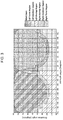
- Figure 3 shows an example of field of regard (FOR) divided into six regions upon the assumption that a twin turret configuration is used for the DIRCM system 2 (such as that one shown in Figure 1 ), wherein a left turret is located on a left side of the aircraft (as the turret 12 shown in Figure 1 ) and a right turret is located on a right side of the aircraft (as the turret 11 shown in Figure 1 ).
- FOR field of regard
- the FOR of the DIRCM system 2 includes:
- the tracking-only turret should, theoretically, keep its laser turned off. But, in this case, with current laser technologies, the laser activation could last tens to hundreds of milliseconds, thereby hindering continuity of the jamming code emission during handover.
- the laser of the tracking-only turret is turned on, but it is steered away from the target.
- Figure 4 shows an aircraft (denoted as a whole by 4), which:
- the missile 5 is countered (i.e., tracked and jammed) by the left DIRCM turret 41 and tracked by the right DIRCM turret 42, while the laser of said right DIRCM turret 42 is aimed away from said missile 5 (specifically, the aiming point of the laser of the tracking-only right DIRCM turret 42 is set outside the laser beam divergence).
- Figure 4 shows also the jamming laser beam (denoted as 43) that is emitted by the left DIRCM turret 41 and is aimed at the missile 5 to jam the latter, along with the laser beam (denoted as 44) that is emitted by the right DIRCM turret 42 and is not aimed at the missile 5.
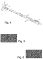
- Figures 5 and 6 show examples of IR pictures captured, respectively, by the right DIRCM turret 42 and the left DIRCM turret 41 (in particular, by the respective IR imaging devices used to track the missile 5) in the scenario shown in Figure 4 .
- the laser of said right DIRCM turret 42 is on the missile 5 very rapidly only by changing its aiming point.
- the SP suite manager 214 master unit conveniently commands the jamming code index from which the right DIRCM turret 42 shall start reproducing the jamming code, thereby guaranteeing jamming code continuity during handover.
- the present invention allows to improve the level of efficacy achievable with DIRCM systems in protecting a generic platform against enemy IR-guided missile attacks.
- the present invention defines new coordination strategies between DIRCM turrets which enable a multiple turret DIRCM system to be, not only, more effective, but also to gain new features not present in a single DIRCM turret or in current multiple (uncoordinated) turret DIRCM configurations.
- the present invention allows to:
Abstract
Description
- The present invention relates, in general, to the field of Electronic Countermeasures (ECMs) and, in particular, to Directed Infrared Countermeasure (DIRCM) systems (sometimes also referred to as Directional Infrared Countermeasures).
- As is known, DIRCM systems are used to defeat infrared (IR) guided missiles, such as those ones launched by man-portable air-defense systems (MANPADS). In particular, a DIRCM system is an active IR countermeasure system designed to be effective against IR seekers of IR-guided missiles (typically, the so-called first three generations of IR seekers).
- Typically, a DIRCM system is designated to a specific target by a Missile Warning System (MWS), which keeps sending an updated list of detected threats (said list reporting a coarse estimation of a direction of arrival of each detected threat). Once activated, a DIRCM system tries to deceive the IR seeker of an approaching IR-guided missile so as to steer the latter away from its target by means of a narrow laser beam, that is constantly kept on the missile and is modulated according to a jamming code related to the seeker's generation(s) which the DIRCM system is designed to be effective against.
- A DIRCM system typically comprises a tracking unit (or tracker), a laser unit and an electronic control unit, wherein:
- the tracker is operable to track an approaching missile (to this end, the tracker conveniently includes an IR imaging device);
- the laser unit is operable to emit a jamming laser beam towards the approaching missile (typically, an IR laser beam modulated according to a predefined frequency jamming code such that to inject spurious signals into the seeker's IR detector of the approaching missile, thereby deceiving missile's IR seeker thus causing the missile to steer away from the platform on which said DIRCM system is installed (typically an aircraft)); and
- the electronic control unit is configured to control operation of the whole DIRCM system and communicate with an on-board command and control system of the platform.
- More in detail, the tracker is typically configured to:
- start tracking a (potential) threat signaled by an on-board MWS of the platform;
- checking whether the signaled threat is an actual approaching missile; and,
- if the signaled threat is an actual approaching missile, activate the laser unit and keep it constantly pointed at the approaching missile so as to keep said approaching missile constantly under the illumination of the jamming laser beam.
- Typically, the tracker and the laser unit are integrated into a steerable turret, which is operable by the tracker to achieve the requested pointing.
- An example of known DIRCM system is provided in
US 2007/0075182 A1 , that discloses a DIRCM system for use on an aircraft to track and jam a missile having an IR missile seeker. - In particular, the DIRCM system according to
US 2007/0075182 A1 comprises: - a pointer-tracker mounted on the aircraft, said pointer-tracker having a detector and a Roll/Nod gimbal that includes optics for collecting incident IR radiation and routing it to the detector and an IR laser transmitter mounted thereon;
- an IR laser optically coupled to the laser transmitter; and
- a missile warner including a receiver that detects a likely missile launch and passes the threat coordinates to the pointer-tracker.
- In detail, the pointer-tracker according to US 2007/0075182 A1 slews the gimbal to the threat coordinates to initiate tracking and then processes the data from its detector to refine tracking of and verify the threat, and, if verified, engages the IR laser to emit a modulated IR laser beam through the laser transmitter to jam the IR missile seeker.
- In order for a DIRCM system to be effective, the following general requirements should be met:
- the DIRCM system should guarantee the most extended visibility region in order to be designated on targets approaching from any direction of arrival;
- upon reception of an alarm from the MWS, the DIRCM system shall guarantee the minimum time to get its laser onto the target;
- during jamming, the DIRCM system shall guarantee its laser to be on target during the whole jamming code replication in order to allow all the jamming code frequencies to reach the engaged seeker.
- Nowadays, typical DIRCM installations are based on single turret configurations or, in case of large platforms, on multiple independent turret configurations, wherein this latter configuration type is used to extend the countermeasure field of regard (FOR) all around the installation platform, assigning to each turret a respective specific sector, every single turret being activated only if a threat is detected in its respective specific sector.
- Single turret DIRCM configurations could lead to have large blind zones around the installation platform where approaching threats are not countered at all. In fact, the FOR of a single turret DIRCM system does not depend only on the DIRCM system itself, but also on the installation platform, which always masks several portions of the theoretically-achievable coverage area, even when considering the most extended possible FOR for the single turret DIRCM system.
- Moreover, single turret DIRCM configurations are limited to protecting a platform against one threat at a time.
- In order to overcome FOR-related limitations of single turret DIRCM configurations, multiple independent turret DIRCM configurations can be used. In particular, this configuration type is exploited to reduce blind zones around large platforms. However, multiple turret DIRCM systems typically lack coordination among the several turrets and this lack of coordination does not allow to counter more than one threat per sector at a time. In particular, in this kind of configurations, the need to assign a specific sector to each turret mainly derives from the lack of a protection mechanism guaranteeing non-destructive interference between different laser beams.
- In this connection,
Figure 1 shows an example of field of regard coverage achievable with a twin turret DIRCM configuration installed on an aircraft (denoted as a whole by 1). In particular,Figure 1 is a bottom view of theaircraft 1, which is equipped with twoDIRCM turrets respective azimuth sector 111/112, wherein saidazimuth sectors common regions - In a traditional approach, no double threat assignment is allowed in the two
common regions common region 113 and 144 are simply assigned to the nearest turret. - The reason for not allowing any assignment of one and the same threat to both the
turrets turrets - The biggest drawback of this approach is that there is no threat handover management when a target passes from the FOR of one turret to the other (such as when the
aircraft 1 performs a maneuver). - An object of the present invention is, thence, that of overcoming, at least in part, the above drawbacks of the current multiple turret DIRCM systems.
- This and other objects are achieved by the present invention in that it relates to a DIRCM system and a related method of operation, as defined in the appended claims.
- In particular, the present invention concerns a method of operation of a DIRCM system for protecting a platform against IR-guided missiles, wherein said DIRCM system comprises a plurality of DIRCM subsystems operable to track and jam IR-guided missiles, and wherein the DIRCM subsystems comprise a first DIRCM subsystem and a second DIRCM subsystem, that are installed on the platform so that:
- said first DIRCM subsystem is operable to track and jam IR-guided missiles in a first coverage region;
- said second DIRCM subsystem is operable to track and jam IR-guided missiles in a second coverage region; and
- both said first and second DIRCM subsystems are operable to track and jam IR-guided missiles in an overlap region, which includes a first handover sub-region adjacent to the first coverage region and a second handover sub-region adjacent to the second coverage region.
- The method comprises:
- if a first missile is in the first coverage region, carrying out a first tracking and jamming operation including tracking and jamming said first missile by the first DIRCM subsystem;
- if the first missile moves from the first coverage region to the overlap region, carrying out a first overlap operation including
- keeping carrying out the first tracking and jamming operation, and
- starting tracking said first missile also by the second DIRCM subsystem; and,
- if the first missile in the overlap region enters the second handover sub-region, carrying out a first handover operation including
- keeping tracking said first missile by the second DIRCM subsystem,
- starting jamming said first missile by said second DIRCM subsystem, and
- stopping carrying out the first tracking and jamming operation.
- For a better understanding of the present invention, preferred embodiments, which are intended purely by way of example and are not to be construed as limiting, will now be described with reference to the attached drawings (not to scale), where:
-
Figure 1 shows an example of field of regard coverage achievable with a twin turret DIRCM configuration installed on an aircraft; -
Figure 2 schematically illustrates a DIRCM system according to a preferred embodiment of the present invention; -
Figure 3 shows an example of field of regard coverage exploitable with the DIRCM system ofFigure 2 , which field of regard coverage is divided into different regions according to a preferred embodiment of an aspect of the present invention; and -
Figures 4-6 illustrate an example of operational scenario of the DIRCM system ofFigure 2 . - The following discussion is presented to enable a person skilled in the art to make and use the invention. Various modifications to the embodiments will be readily apparent to those skilled in the art, without departing from the scope of the present invention as claimed. Thus, the present invention is not intended to be limited to the embodiments shown and described, but is to be accorded the widest scope consistent with the principles and features disclosed herein and defined in the appended claims.
- The present invention concerns a DIRCM system and a related method of operation. In particular, the DIRCM system according to the present invention is designed to protect a platform (such as land platform or vehicle, an avionic platform, or a naval unit) against infrared-guided missiles, and comprises two or more DIRCM subsystems operable to track and jam IR-guided missiles, wherein said DIRCM subsystems comprise a first DIRCM subsystem and a second DIRCM subsystem, that are installed on the platform so that:
- said first DIRCM subsystem is operable to track and jam IR-guided missiles in a first coverage region;
- said second DIRCM subsystem is operable to track and jam IR-guided missiles in a second coverage region; and
- both said first and second DIRCM subsystems are operable to track and jam IR-guided missiles in an overlap region, which includes a first handover sub-region adjacent to the first coverage region and a second handover sub-region adjacent to the second coverage region.
- In detail, the method of operation according to the present invention comprises:
- if a first missile is in the first coverage region, carrying out a first tracking and jamming operation including tracking and jamming said first missile by the first DIRCM subsystem;
- if the first missile moves from the first coverage region to the overlap region, carrying out a first overlap operation including
- keeping carrying out the first tracking and jamming operation, and
- starting tracking said first missile also by the second DIRCM subsystem; and,
- if the first missile in the overlap region enters the second handover sub-region (while it is being tracked and jammed by the first DIRCM subsystem and (only) tracked by the second DIRCM subsystem), carrying out a first handover operation including
- keeping tracking said first missile by the second DIRCM subsystem,
- starting jamming said first missile by said second DIRCM subsystem, and
- stopping carrying out the first tracking and jamming operation.
- Preferably, the first DIRCM subsystem includes:
- first tracking means operable to track infrared-guided missiles in the first coverage region and in the overlap region; and
- first laser means operable to emit laser beams to jam infrared-guided missiles in the first coverage region and in the overlap region.
- Moreover, the second DIRCM subsystem preferably includes:
- second tracking means operable to track infrared-guided missiles in the second coverage region and in the overlap region; and
- second laser means operable to emit laser beams to jam infrared-guided missiles in the second coverage region and in the overlap region.
- Furthermore, the first tracking and jamming operation preferably includes:
- tracking the first missile by the first tracking means; and
- emitting a first laser beam aimed at the first missile by the first laser means thereby jamming said first missile.
- Additionally, the first overlap operation preferably includes starting:
- tracking the first missile by the second tracking means; and
- emitting a second laser beam by the second laser means, wherein said second laser beam is not aimed at said first missile.
- Again preferably, the first handover operation includes:
- keeping tracking the first missile by the second tracking means; and
- aiming the second laser beam at the first missile thereby starting jamming said first missile by the second laser means.
- More preferably, the first laser beam is modulated according to a first jamming code, and the first overlap operation includes starting emitting a second laser beam that is modulated according to said first jamming code and is synchronized with said first laser beam.
- Conveniently, the first overlap operation is carried out only if the second DIRCM subsystem is not countering any missile.
- Again conveniently, the method of operation further comprises:
- if the first missile moves from the first coverage region to the second coverage region,
- stopping carrying out the first tracking and jamming operation, and
- starting tracking and jamming said first missile by the second DIRCM subsystem.
- Preferably, the method of operation further comprises:
- if a second missile is in the second coverage region, carrying out a second tracking and jamming operation including tracking and jamming said second missile by the second DIRCM subsystem;
- if the second missile moves from the second coverage region to the overlap region, carrying out a second overlap operation including
- keeping carrying out the second tracking and jamming operation, and
- starting tracking said second missile also by the first DIRCM subsystem; and,
- if the second missile in the overlap region enters the first handover sub-region (while it is being tracked and jammed by the second DIRCM subsystem and (only) tracked by the first DIRCM subsystem), carrying out a second handover operation including
- keeping tracking said second missile by the first DIRCM subsystem,
- starting jamming said second missile by said first DIRCM subsystem, and
- stopping carrying out the second tracking and jamming operation.
- More preferably, the second tracking and jamming operation includes:
- tracking the second missile by the second tracking means; and
- emitting a third laser beam aimed at the second missile by the second laser means thereby jamming said second missile.
- Moreover, the second overlap operation preferably includes starting:
- tracking the second missile by the first tracking means; and
- emitting a fourth laser beam by the first laser means, wherein said fourth laser beam is not aimed at said second missile.
- Additionally, the second handover operation preferably includes:
- keeping tracking the second missile by the first tracking means; and
- aiming the fourth laser beam at the second missile thereby starting jamming said second missile by the first laser means.
- More and more preferably, the third laser beam is modulated according to a second jamming code, and the second overlap operation includes starting emitting a fourth laser beam that is modulated according to said second jamming code and is synchronized with said third laser beam.
- Conveniently, the second overlap operation is carried out only if the first directed infrared countermeasure subsystem is not countering any missile.
- Again conveniently, the method of operation further comprises:
- if the second missile moves from the second coverage region to the first coverage region,
- stopping carrying out the second tracking and jamming operation, and
- starting tracking and jamming said second missile by the first directed infrared countermeasure subsystem.
- Preferably, the DIRCM system comprises a managing unit, that is:
- coupled to a MWS installed on the platform to receive threat-related data indicating a threat scenario; and
- configured to coordinate activation and operation of the DIRCM subsystems on the basis of the received threat-related data.
- More conveniently, the managing unit is programmed to operate the DIRCM subsystems on the basis of:
- the threat scenario indicated by the received threat-related data;
- a current state of the DIRCM subsystems; and
- a predefined designation logic indicating, for a predefined set of threat scenarios and directed infrared countermeasure subsystem states, corresponding ways of operating the DIRCM subsystems.
- In the following, only for the sake of description simplicity and, thence, without losing generality, a preferred embodiment of the present invention will be described in detail by making explicit reference to a DIRCM system installed on an aircraft and comprising only two DIRCM subsystems (turrets). Anyway, it is important to stress the point that the present invention can be advantageously exploited, without any substantial modification, with any number of subsystems (turrets) higher than two, and on board platforms of any type, such as:
- land platforms or vehicles, conveniently of the military type (e.g., armoured military vehicles, tanks, mine-clearance vehicles, armed land vehicles, etc.);
- avionic platforms, conveniently of the military type (e.g., aircrafts, helicopters, drones, etc.); and
- naval units, conveniently of the military type (e.g., cruisers, patrol boats, corvettes, etc.).
- For a better understanding of the present invention,
Figure 2 shows a block diagram schematically representing a functional architecture of a DIRCM system (denoted as a whole by 2) according to a preferred embodiment of the present invention. - In particular, the
DIRCM system 2 is installed on an aircraft (not shown inFigure 2 ) and comprises: - a
master DIRCM subsystem 21, that includes afirst DIRCM manager 211, a firstthermal tracker 212, afirst laser unit 213, and a self-protection (SP)suite manager 214; and - a
slave DIRCM subsystem 22, that includes asecond DIRCM manager 221, a secondthermal tracker 222 and asecond laser unit 223. - In detail, the
first DIRCM manager 211 is configured to control operation of the firstthermal tracker 212 and of thefirst laser unit 213, the first thermal tracker 212 (which conveniently includes a respective IR imaging device) is operable to track threats, thefirst laser unit 213 is operable to generate laser beams used for IR countermeasures, thesecond DIRCM manager 221 is configured to control operation of the secondthermal tracker 222 and of thesecond laser unit 223, the second thermal tracker 222 (which conveniently includes a respective IR imaging device) is operable to track threats, thesecond laser unit 223 is operable to generate laser beams used for IR countermeasures, and theSP suite manager 214 is configured to control operation of thewhole DIRCM system 2. - Preferably, the
SP suite manager 214 is a software-implemented function, which is implemented only in themaster DIRCM subsystem 21, and which is in charge of: - interfacing with a
MWS 3 installed on the aircraft and with an on-board command and control system (not shown inFigure 2 ) of the aircraft; and - coordinating activation and operation of the master and
slave DIRCM subsystems - In particular, in use, the designation of the master and
slave DIRCM subsystems SP suite manager 214 on the basis of a current threat scenario provided by theMWS 3 and of a current engagement state of the master andslave DIRCM subsystems slave DIRCM subsystems 21 and 22 (i.e., for the DIRCM turrets). - Therefore, the use of a software-implemented, reprogrammable table renders the
DIRCM system 2 flexible, easily (re)programmable by electronic warfare (EW) operators with their own designation rules and, thence, fully customizable. - Moreover, it is worth noting also that the use of the aforesaid table storing/defining designation commands depending on threat scenario and engagement state substantially wipes out decision time of the
SP suite manager 214, since the latter has only to read the table without carrying out any designation-oriented processing. - Conveniently, the first
thermal tracker 212 and thefirst laser unit 213 are integrated into one and the same first steerable turret (not shown inFigure 2 ), while the secondthermal tracker 222 and thesecond laser unit 223 are integrated into one and the same second steerable turret (not shown inFigure 2 ), wherein said first and second turrets are installed on the aircraft in different positions (for example, they can be conveniently located in the same positions as those of theDIRCM turrets aircraft 1 shown inFigure 1 ). - Moreover, the above functions of the
first DIRCM manager 211 and of theSP suite manager 214 could be conveniently implemented: - by one and same electronic control unit, that is programmed to implement said functions, and that is integrated into said first steerable turret or installed in another position on the aircraft; or
- by a first electronic control unit and a second control unit that are connected to each other and programmed to implement the functions, respectively, of the
first DIRCM manager 211 and of theSP suite manager 214; wherein the first electronic control unit can be integrated into said first steerable turret or installed in another position on the aircraft, and the second control unit can be integrated into said first steerable turret or installed in another position on the aircraft. - Also the functions of the
second DIRCM manager 221 can be conveniently implemented by a respective electronic control unit integrated into the second steerable turret or installed in another position on the aircraft. - According to an aspect of the present invention, in order to identify which turret is to be designated to a specific target reported by the
MWS 3, the FOR of theDIRCM system 2 is divided into different regions. - In this connection,
Figure 3 shows an example of field of regard (FOR) divided into six regions upon the assumption that a twin turret configuration is used for the DIRCM system 2 (such as that one shown inFigure 1 ), wherein a left turret is located on a left side of the aircraft (as theturret 12 shown inFigure 1 ) and a right turret is located on a right side of the aircraft (as theturret 11 shown inFigure 1 ). - In particular, in the example shown in
Figure 3 the FOR of theDIRCM system 2 includes: - a "Left Turret Region" where only the left turret is designated;
- a "Left Handover Region", wherein, if a threat already countered by the right turret reaches this region, the handover to the left turret is triggered;
- a "Left Overlap Region" where a threat is countered by the left turret and tracked by the right turret, if available (i.e., if the latter is not already countering another threat);
- a "Right Overlap Region" where a threat is countered by the right turret and tracked by the left turret, if available (i.e., if the latter is not already countering another threat);
- a "Right Handover Region", wherein, if a threat already countered by the left turret reaches this region, the handover to the right turret is triggered; and
- a "Right Turret Region" where only the right turret is designated.
- The idea of designating both turrets in overlap regions, one jamming the threat and the other one only tracking it, is intended to cope with turret handover of threats. More specifically, since in the Left and Right Overlap Regions the tracking-only turret is already tracking the threat while it can receive an handover command, the turret handover occurs with no delay (in fact, said tracking-only turret is already on its target).
- Moreover, it is worth noting that, in order to guarantee non-destructive interference between the two lasers in the Left and Right Overlap Regions, the tracking-only turret should, theoretically, keep its laser turned off. But, in this case, with current laser technologies, the laser activation could last tens to hundreds of milliseconds, thereby hindering continuity of the jamming code emission during handover.
- Therefore, in order to avoid laser interference and, at the same time, to guarantee the laser on target as fast as possible, in the Left and Right Overlap Regions the laser of the tracking-only turret is turned on, but it is steered away from the target.
- In this connection,
Figure 4 shows an aircraft (denoted as a whole by 4), which: - is equipped with a
left DIRCM turret 41, that includes themaster DIRCM subsystem 21 and is installed on a left side of saidaircraft 4; - is equipped with a
right DIRCM turret 42, that includes theslave DIRCM subsystem 22 and is installed on a right side of saidaircraft 4; and - is under the threat of an IR-guided
missile 5 that is in the Left Overlap Region. - In other words, the
missile 5 is countered (i.e., tracked and jammed) by theleft DIRCM turret 41 and tracked by theright DIRCM turret 42, while the laser of saidright DIRCM turret 42 is aimed away from said missile 5 (specifically, the aiming point of the laser of the tracking-onlyright DIRCM turret 42 is set outside the laser beam divergence). - In this respect,
Figure 4 shows also the jamming laser beam (denoted as 43) that is emitted by theleft DIRCM turret 41 and is aimed at themissile 5 to jam the latter, along with the laser beam (denoted as 44) that is emitted by theright DIRCM turret 42 and is not aimed at themissile 5. - Additionally,
Figures 5 and 6 show examples of IR pictures captured, respectively, by theright DIRCM turret 42 and the left DIRCM turret 41 (in particular, by the respective IR imaging devices used to track the missile 5) in the scenario shown inFigure 4 . - Therefore, if handover between the
left DIRCM turret 41 and theright DIRCM turret 42 is to be performed, the laser of saidright DIRCM turret 42 is on themissile 5 very rapidly only by changing its aiming point. - Furthermore, once the
right DIRCM turret 42 becomes the countering system (i.e., in case of threat handover), theSP suite manager 214 master unit conveniently commands the jamming code index from which theright DIRCM turret 42 shall start reproducing the jamming code, thereby guaranteeing jamming code continuity during handover. - The advantages of the present invention are clear from the foregoing.
- In particular, it is worth highlighting the fact that the present invention allows to improve the level of efficacy achievable with DIRCM systems in protecting a generic platform against enemy IR-guided missile attacks.
- Moreover, the present invention defines new coordination strategies between DIRCM turrets which enable a multiple turret DIRCM system to be, not only, more effective, but also to gain new features not present in a single DIRCM turret or in current multiple (uncoordinated) turret DIRCM configurations.
- Additionally, the present invention allows to:
- extend DIRCM system's field of regard for the protection of a platform of interest;
- guarantee non-destructive interference between the laser beams of the turrets during the jamming;
- be effective against more than one threat simultaneously with programmable designation strategies;
- manage effectively the handover of the threat among the turrets during platform maneuvers, still guaranteeing the jamming code reproduction continuity on target; and
- have a completely redundant system architecture with capabilities to change on-the-fly the mastership from one DIRCM subsystem to another in case of severe malfunctioning (degraded operational modes).
Claims (15)
- Method of operation of a directed infrared countermeasure system (2) for protecting a platform (4) against infrared-guided missiles (5), wherein said directed infrared countermeasure system (2) comprises a plurality of directed infrared countermeasure subsystems (21,22) operable to track and jam infrared-guided missiles (5); wherein the directed infrared countermeasure subsystems comprise a first directed infrared countermeasure subsystem (21) and a second directed infrared countermeasure subsystem (22), that are installed on the platform (4) so that:• said first directed infrared countermeasure subsystem (21) is operable to track and jam infrared-guided missiles (5) in a first coverage region;• said second directed infrared countermeasure subsystem (22) is operable to track and jam infrared-guided missiles (5) in a second coverage region; and• both said first and second directed infrared countermeasure subsystems (21,22) are operable to track and jam infrared-guided missiles (5) in an overlap region, which includes a first handover sub-region adjacent to the first coverage region and a second handover sub-region adjacent to the second coverage region;the method comprising:• if a first missile (5) is in the first coverage region, carrying out a first tracking and jamming operation including tracking and jamming said first missile (5) by the first directed infrared countermeasure subsystem (21);• if the first missile (5) moves from the first coverage region to the overlap region, carrying out a first overlap operation including- keeping carrying out the first tracking and jamming operation, and- starting tracking said first missile (5) also by the second directed infrared countermeasure subsystem (22); and,• if the first missile (5) in the overlap region enters the second handover sub-region, carrying out a first handover operation including- keeping tracking said first missile (5) by the second directed infrared countermeasure subsystem (22),- starting jamming said first missile (5) by said second directed infrared countermeasure subsystem (22), and- stopping carrying out the first tracking and jamming operation.
- The method of claim 1, wherein the first directed infrared countermeasure subsystem (21) includes:• first tracking means (212) operable to track infrared-guided missiles (5) in the first coverage region and in the overlap region; and• first laser means (213) operable to emit laser beams to jam infrared-guided missiles (5) in the first coverage region and in the overlap region;wherein the second directed infrared countermeasure subsystem (22) includes:• second tracking means (222) operable to track infrared-guided missiles (5) in the second coverage region and in the overlap region; and• second laser means (223) operable to emit laser beams to jam infrared-guided missiles (5) in the second coverage region and in the overlap region;wherein the first tracking and jamming operation includes:• tracking the first missile (5) by the first tracking means (212); and• emitting a first laser beam aimed at the first missile (5) by the first laser means (213) thereby jamming said first missile (5);wherein the first overlap operation includes starting:• tracking the first missile (5) by the second tracking means (222); and• emitting a second laser beam by the second laser means (223), wherein said second laser beam is not aimed at said first missile (5);and wherein the first handover operation includes:• keeping tracking the first missile (5) by the second tracking means (222); and• aiming the second laser beam at the first missile (5) thereby starting jamming said first missile (5) by the second laser means (223).
- The method of claim 2, wherein the first laser beam is modulated according to a first jamming code; and wherein the first overlap operation includes starting emitting a second laser beam that is modulated according to said first jamming code and is synchronized with said first laser beam.
- The method according to any claim 1-3, wherein the first overlap operation is carried out only if the second directed infrared countermeasure subsystem (22) is not countering any missile.
- The method according to any preceding claim, further comprising:• if the first missile (5) moves from the first coverage region to the second coverage region,- stopping carrying out the first tracking and jamming operation, and- starting tracking and jamming said first missile (5) by the second directed infrared countermeasure subsystem (22).
- The method according to any preceding claim, further comprising:• if a second missile (5) is in the second coverage region, carrying out a second tracking and jamming operation including tracking and jamming said second missile (5) by the second directed infrared countermeasure subsystem (22);• if the second missile (5) moves from the second coverage region to the overlap region, carrying out a second overlap operation including- keeping carrying out the second tracking and jamming operation, and- starting tracking said second missile (5) also by the first directed infrared countermeasure subsystem (21); and,• if the second missile (5) in the overlap region enters the first handover sub-region, carrying out a second handover operation including- keeping tracking said second missile (5) by the first directed infrared countermeasure subsystem (21),- starting jamming said second missile (5) by said first directed infrared countermeasure subsystem (21), and- stopping carrying out the second tracking and jamming operation.
- The method of claim 6, wherein the first directed infrared countermeasure subsystem (21) includes:• first tracking means (212) operable to track infrared-guided missiles (5) in the first coverage region and in the overlap region; and• first laser means (213) operable to emit laser beams to jam infrared-guided missiles (5) in the first coverage region and in the overlap region;wherein the second directed infrared countermeasure subsystem (22) includes:• second tracking means (222) operable to track infrared-guided missiles (5) in the second coverage region and in the overlap region; and• second laser means (223) operable to emit laser beams to jam infrared-guided missiles (5) in the second coverage region and in the overlap region;wherein the second tracking and jamming operation includes:• tracking the second missile (5) by the second tracking means (222); and• emitting a third laser beam aimed at the second missile (5) by the second laser means (223) thereby jamming said second missile (5);wherein the second overlap operation includes starting:• tracking the second missile (5) by the first tracking means (212); and• emitting a fourth laser beam by the first laser means (213), wherein said fourth laser beam is not aimed at said second missile (5);and wherein the second handover operation includes:• keeping tracking the second missile (5) by the first tracking means (212); and• aiming the fourth laser beam at the second missile (5) thereby starting jamming said second missile (5) by the first laser means (213).
- The method of claim 7, wherein the third laser beam is modulated according to a second jamming code; and wherein the second overlap operation includes starting emitting a fourth laser beam that is modulated according to said second jamming code and is synchronized with said third laser beam.
- The method according to any claim 6-8, wherein the second overlap operation is carried out only if the first directed infrared countermeasure subsystem (21) is not countering any missile.
- The method according to any claim 6-9, further comprising:• if the second missile (5) moves from the second coverage region to the first coverage region,- stopping carrying out the second tracking and jamming operation, and- starting tracking and jamming said second missile (5) by the first directed infrared countermeasure subsystem (21).
- Directed infrared countermeasure system (2) for protecting a platform (4) against infrared-guided missiles (5), said directed infrared countermeasure system (2) comprising a plurality of directed infrared countermeasure subsystems (21,22) operable to track and jam infrared-guided missiles (5); wherein the directed infrared countermeasure subsystems comprise a first directed infrared countermeasure subsystem (21) and a second directed infrared countermeasure subsystem (22), that are installed on the platform (4) so that:• said first directed infrared countermeasure subsystem (21) is operable to track and jam infrared-guided missiles (5) in a first coverage region;• said second directed infrared countermeasure subsystem (22) is operable to track and jam infrared-guided missiles (5) in a second coverage region; and• both said first and second directed infrared countermeasure subsystems (21,22) are operable to track and jam infrared-guided missiles (5) in an overlap region, which includes a first handover sub-region adjacent to the first coverage region and a second handover sub-region adjacent to the second coverage region;said directed infrared countermeasure system (2) being configured to carry out the method of operation as claimed in any preceding claim.
- The directed infrared countermeasure system of claim 11, further comprising a managing unit (214), that is:• coupled to a missile warning system (3) installed on the platform (4) to receive threat-related data indicating a threat scenario; and• configured to coordinate activation and operation of the directed infrared countermeasure subsystems (21,22) on the basis of the received threat-related data.
- The directed infrared countermeasure system of claim 12, wherein the managing unit (214) is programmed to operate the directed infrared countermeasure subsystems (21,22) on the basis of:• the threat scenario indicated by the received threat-related data;• a current state of the directed infrared countermeasure subsystems (21,22); and• a predefined designation logic indicating, for a predefined set of threat scenarios and directed infrared countermeasure subsystem states, corresponding ways of operating the directed infrared countermeasure subsystems (21,22).
- Platform (4) equipped with the directed infrared countermeasure system as claimed in any claim 11-13.
- The platform of claim 14, wherein said platform is a land platform or vehicle, or an avionic platform (4), or a naval unit.
Priority Applications (1)
| Application Number | Priority Date | Filing Date | Title |
|---|---|---|---|
| EP16165697.0A EP3081895B1 (en) | 2015-04-17 | 2016-04-16 | Multiple turret dircm system and related method of operation |
Applications Claiming Priority (2)
| Application Number | Priority Date | Filing Date | Title |
|---|---|---|---|
| EP15425030 | 2015-04-17 | ||
| EP16165697.0A EP3081895B1 (en) | 2015-04-17 | 2016-04-16 | Multiple turret dircm system and related method of operation |
Publications (2)
| Publication Number | Publication Date |
|---|---|
| EP3081895A1 true EP3081895A1 (en) | 2016-10-19 |
| EP3081895B1 EP3081895B1 (en) | 2018-06-06 |
Family
ID=56108449
Family Applications (1)
| Application Number | Title | Priority Date | Filing Date |
|---|---|---|---|
| EP16165697.0A Active EP3081895B1 (en) | 2015-04-17 | 2016-04-16 | Multiple turret dircm system and related method of operation |
Country Status (5)
| Country | Link |
|---|---|
| EP (1) | EP3081895B1 (en) |
| AU (1) | AU2016202384B2 (en) |
| CA (1) | CA2927269C (en) |
| ES (1) | ES2681668T3 (en) |
| SG (1) | SG10201602952VA (en) |
Cited By (10)
| Publication number | Priority date | Publication date | Assignee | Title |
|---|---|---|---|---|
| EP3410148A1 (en) * | 2017-06-02 | 2018-12-05 | BAE SYSTEMS plc | Weapon system |
| EP3410149A1 (en) * | 2017-06-02 | 2018-12-05 | BAE SYSTEMS plc | Weapon system |
| WO2018220381A1 (en) * | 2017-06-02 | 2018-12-06 | Bae Systems Plc | Weapon system |
| WO2018220382A1 (en) * | 2017-06-02 | 2018-12-06 | Bae Systems Plc | Weapon system |
| WO2019120555A1 (en) | 2017-12-21 | 2019-06-27 | Elettronica S.P.A. | Ircm system based on coordinated management of flares and dircm systems for protection against ir-guided missiles |
| WO2019180707A1 (en) * | 2018-03-19 | 2019-09-26 | Elbit Systems Electro-Optics Elop Ltd. | System and method for carrying out a flexible handover between multiple energy directing elements |
| EP3702720A1 (en) * | 2019-02-20 | 2020-09-02 | Diehl Defence GmbH & Co. KG | Dircm with simplified transfer between modules |
| EP3751226A1 (en) * | 2019-06-12 | 2020-12-16 | Diehl Defence GmbH & Co. KG | Dircm with predictive transfer between modules |
| EP3800483A1 (en) * | 2019-10-04 | 2021-04-07 | Diehl Defence GmbH & Co. KG | Alignment of a detector of a dircm module relative to a target |
| EP3699544B1 (en) * | 2019-02-20 | 2024-03-27 | Diehl Defence GmbH & Co. KG | Dircm with dual target tracking |
Families Citing this family (2)
| Publication number | Priority date | Publication date | Assignee | Title |
|---|---|---|---|---|
| WO2019077572A1 (en) | 2017-10-20 | 2019-04-25 | Elettronica S.P.A. | Distributed system of detection and countermeasure of ir-guided missiles |
| DE102020004949A1 (en) | 2020-08-14 | 2022-02-17 | Diehl Defence Gmbh & Co. Kg | DIRCM with self-sufficient overlap-free handover between modules |
Citations (5)
| Publication number | Priority date | Publication date | Assignee | Title |
|---|---|---|---|---|
| JP2006207891A (en) * | 2005-01-26 | 2006-08-10 | Toshiba Corp | Light-wave interfering device |
| US20070075182A1 (en) | 2005-10-04 | 2007-04-05 | Raytheon Company | Directed infrared countermeasures (DIRCM) system and method |
| WO2008062401A1 (en) * | 2006-11-21 | 2008-05-29 | Rafael - Armament Development Authority Ltd. | Laser based countermeasures system and method |
| EP2442131A1 (en) * | 2006-04-10 | 2012-04-18 | Elta Systems Ltd. | Distributed jammer system |
| EP2527865A1 (en) * | 2011-05-24 | 2012-11-28 | Bird Aerosystems Ltd. | System, device and method of protecting aircrafts against incoming missiles and threats |
-
2016
- 2016-04-14 SG SG10201602952VA patent/SG10201602952VA/en unknown
- 2016-04-15 AU AU2016202384A patent/AU2016202384B2/en active Active
- 2016-04-16 ES ES16165697.0T patent/ES2681668T3/en active Active
- 2016-04-16 EP EP16165697.0A patent/EP3081895B1/en active Active
- 2016-04-18 CA CA2927269A patent/CA2927269C/en active Active
Patent Citations (5)
| Publication number | Priority date | Publication date | Assignee | Title |
|---|---|---|---|---|
| JP2006207891A (en) * | 2005-01-26 | 2006-08-10 | Toshiba Corp | Light-wave interfering device |
| US20070075182A1 (en) | 2005-10-04 | 2007-04-05 | Raytheon Company | Directed infrared countermeasures (DIRCM) system and method |
| EP2442131A1 (en) * | 2006-04-10 | 2012-04-18 | Elta Systems Ltd. | Distributed jammer system |
| WO2008062401A1 (en) * | 2006-11-21 | 2008-05-29 | Rafael - Armament Development Authority Ltd. | Laser based countermeasures system and method |
| EP2527865A1 (en) * | 2011-05-24 | 2012-11-28 | Bird Aerosystems Ltd. | System, device and method of protecting aircrafts against incoming missiles and threats |
Cited By (16)
| Publication number | Priority date | Publication date | Assignee | Title |
|---|---|---|---|---|
| US10883803B2 (en) | 2017-06-02 | 2021-01-05 | Bae Systems Plc | Weapon system |
| EP3410149A1 (en) * | 2017-06-02 | 2018-12-05 | BAE SYSTEMS plc | Weapon system |
| WO2018220381A1 (en) * | 2017-06-02 | 2018-12-06 | Bae Systems Plc | Weapon system |
| WO2018220382A1 (en) * | 2017-06-02 | 2018-12-06 | Bae Systems Plc | Weapon system |
| EP3410148A1 (en) * | 2017-06-02 | 2018-12-05 | BAE SYSTEMS plc | Weapon system |
| AU2018277595B2 (en) * | 2017-06-02 | 2022-08-18 | Bae Systems Plc | Weapon system |
| AU2018277594B2 (en) * | 2017-06-02 | 2022-06-16 | Bae Systems Plc | Weapon system |
| US10883802B2 (en) | 2017-06-02 | 2021-01-05 | Bae Systems Plc | Weapon system |
| WO2019120555A1 (en) | 2017-12-21 | 2019-06-27 | Elettronica S.P.A. | Ircm system based on coordinated management of flares and dircm systems for protection against ir-guided missiles |
| EP3769511A4 (en) * | 2018-03-19 | 2021-05-05 | Elbit Systems Electro-Optics Elop Ltd. | System and method for carrying out a flexible handover between multiple energy directing elements |
| WO2019180707A1 (en) * | 2018-03-19 | 2019-09-26 | Elbit Systems Electro-Optics Elop Ltd. | System and method for carrying out a flexible handover between multiple energy directing elements |
| EP3702720A1 (en) * | 2019-02-20 | 2020-09-02 | Diehl Defence GmbH & Co. KG | Dircm with simplified transfer between modules |
| EP3699544B1 (en) * | 2019-02-20 | 2024-03-27 | Diehl Defence GmbH & Co. KG | Dircm with dual target tracking |
| EP3751226A1 (en) * | 2019-06-12 | 2020-12-16 | Diehl Defence GmbH & Co. KG | Dircm with predictive transfer between modules |
| EP3800483A1 (en) * | 2019-10-04 | 2021-04-07 | Diehl Defence GmbH & Co. KG | Alignment of a detector of a dircm module relative to a target |
| DE102019006925A1 (en) * | 2019-10-04 | 2021-04-08 | Diehl Defence Gmbh & Co. Kg | Alignment of a detector of a DIRCM module to a target |
Also Published As
| Publication number | Publication date |
|---|---|
| ES2681668T3 (en) | 2018-09-14 |
| SG10201602952VA (en) | 2016-11-29 |
| EP3081895B1 (en) | 2018-06-06 |
| AU2016202384B2 (en) | 2020-11-12 |
| AU2016202384A1 (en) | 2016-11-03 |
| CA2927269A1 (en) | 2016-10-17 |
| CA2927269C (en) | 2023-07-25 |
Similar Documents
| Publication | Publication Date | Title |
|---|---|---|
| AU2016202384B2 (en) | Multiple turret dircm system and related method of operation | |
| US7925159B2 (en) | Non-directional laser-based self-protection | |
| US9523548B2 (en) | Operational control logic for harmonized turret with gimbaled sub-systems | |
| US7212148B1 (en) | Apparatus for jamming infrared attack unit using a modulated radio frequency carrier | |
| US11181346B1 (en) | Methods for enhanced soft-kill countermeasure using a tracking radar | |
| US9244459B2 (en) | Reflexive response system for popup threat survival | |
| US8927935B1 (en) | All electro optical based method for deconfliction of multiple, co-located directed energy, high energy laser platforms on multiple, near simultaneous threat targets in the same battle space | |
| EP2442131A1 (en) | Distributed jammer system | |
| JP2019023553A (en) | Drone-based active protection system | |
| WO2019077572A1 (en) | Distributed system of detection and countermeasure of ir-guided missiles | |
| JP5697734B1 (en) | Mobile electronic control device | |
| EP3728984B1 (en) | Ircm system based on coordinated management of flares and dircm systems for protection against ir-guided missiles | |
| US20230400282A1 (en) | Countermeasure system having a confirmation device and method thereof | |
| EP2959260B1 (en) | Method and arrangement for threat management for ground-based vehicle | |
| US11860632B2 (en) | Weapon system | |
| JP2018091713A (en) | Tracking device and multi-sensor system | |
| US20230282124A1 (en) | System for collaborative threat evasion tactics coordination | |
| JP6713918B2 (en) | Electronic warfare device and multi-sensor system | |
| JP7246159B2 (en) | Defense systems, vehicle systems and multi-sensor systems | |
| US10101455B1 (en) | Apparatus utilizing electro-optical/infrared threat warning, proactive and reactive countermeasures | |
| Rudd-Orthner et al. | A Naval Combat Management System (CMS) Architecture to enable Cognitive Electronic Warfare in Platform Protection | |
| WO2009002300A1 (en) | Non-directional laser-based self-protection | |
| Yannone | The powerful role of the Commanders Decision Aid (CDS) software and acoustic sensor to increasing ground combat vehicle survivability |
Legal Events
| Date | Code | Title | Description |
|---|---|---|---|
| PUAI | Public reference made under article 153(3) epc to a published international application that has entered the european phase |
Free format text: ORIGINAL CODE: 0009012 |
|
| AK | Designated contracting states |
Kind code of ref document: A1 Designated state(s): AL AT BE BG CH CY CZ DE DK EE ES FI FR GB GR HR HU IE IS IT LI LT LU LV MC MK MT NL NO PL PT RO RS SE SI SK SM TR |
|
| AX | Request for extension of the european patent |
Extension state: BA ME |
|
| STAA | Information on the status of an ep patent application or granted ep patent |
Free format text: STATUS: REQUEST FOR EXAMINATION WAS MADE |
|
| 17P | Request for examination filed |
Effective date: 20170419 |
|
| RBV | Designated contracting states (corrected) |
Designated state(s): AL AT BE BG CH CY CZ DE DK EE ES FI FR GB GR HR HU IE IS IT LI LT LU LV MC MK MT NL NO PL PT RO RS SE SI SK SM TR |
|
| GRAP | Despatch of communication of intention to grant a patent |
Free format text: ORIGINAL CODE: EPIDOSNIGR1 |
|
| STAA | Information on the status of an ep patent application or granted ep patent |
Free format text: STATUS: GRANT OF PATENT IS INTENDED |
|
| RIC1 | Information provided on ipc code assigned before grant |
Ipc: F41G 7/22 20060101ALI20171128BHEP Ipc: F41H 13/00 20060101AFI20171128BHEP |
|
| INTG | Intention to grant announced |
Effective date: 20171212 |
|
| GRAS | Grant fee paid |
Free format text: ORIGINAL CODE: EPIDOSNIGR3 |
|
| GRAA | (expected) grant |
Free format text: ORIGINAL CODE: 0009210 |
|
| STAA | Information on the status of an ep patent application or granted ep patent |
Free format text: STATUS: THE PATENT HAS BEEN GRANTED |
|
| AK | Designated contracting states |
Kind code of ref document: B1 Designated state(s): AL AT BE BG CH CY CZ DE DK EE ES FI FR GB GR HR HU IE IS IT LI LT LU LV MC MK MT NL NO PL PT RO RS SE SI SK SM TR |
|
| REG | Reference to a national code |
Ref country code: GB Ref legal event code: FG4D |
|
| REG | Reference to a national code |
Ref country code: CH Ref legal event code: EP Ref country code: AT Ref legal event code: REF Ref document number: 1006585 Country of ref document: AT Kind code of ref document: T Effective date: 20180615 |
|
| REG | Reference to a national code |
Ref country code: IE Ref legal event code: FG4D |
|
| REG | Reference to a national code |
Ref country code: DE Ref legal event code: R096 Ref document number: 602016003281 Country of ref document: DE |
|
| REG | Reference to a national code |
Ref country code: SE Ref legal event code: TRGR |
|
| REG | Reference to a national code |
Ref country code: ES Ref legal event code: FG2A Ref document number: 2681668 Country of ref document: ES Kind code of ref document: T3 Effective date: 20180914 |
|
| REG | Reference to a national code |
Ref country code: NL Ref legal event code: MP Effective date: 20180606 |
|
| REG | Reference to a national code |
Ref country code: LT Ref legal event code: MG4D |
|
| PG25 | Lapsed in a contracting state [announced via postgrant information from national office to epo] |
Ref country code: BG Free format text: LAPSE BECAUSE OF FAILURE TO SUBMIT A TRANSLATION OF THE DESCRIPTION OR TO PAY THE FEE WITHIN THE PRESCRIBED TIME-LIMIT Effective date: 20180906 Ref country code: CY Free format text: LAPSE BECAUSE OF FAILURE TO SUBMIT A TRANSLATION OF THE DESCRIPTION OR TO PAY THE FEE WITHIN THE PRESCRIBED TIME-LIMIT Effective date: 20180606 Ref country code: NO Free format text: LAPSE BECAUSE OF FAILURE TO SUBMIT A TRANSLATION OF THE DESCRIPTION OR TO PAY THE FEE WITHIN THE PRESCRIBED TIME-LIMIT Effective date: 20180906 Ref country code: FI Free format text: LAPSE BECAUSE OF FAILURE TO SUBMIT A TRANSLATION OF THE DESCRIPTION OR TO PAY THE FEE WITHIN THE PRESCRIBED TIME-LIMIT Effective date: 20180606 Ref country code: LT Free format text: LAPSE BECAUSE OF FAILURE TO SUBMIT A TRANSLATION OF THE DESCRIPTION OR TO PAY THE FEE WITHIN THE PRESCRIBED TIME-LIMIT Effective date: 20180606 |
|
| PG25 | Lapsed in a contracting state [announced via postgrant information from national office to epo] |
Ref country code: LV Free format text: LAPSE BECAUSE OF FAILURE TO SUBMIT A TRANSLATION OF THE DESCRIPTION OR TO PAY THE FEE WITHIN THE PRESCRIBED TIME-LIMIT Effective date: 20180606 Ref country code: HR Free format text: LAPSE BECAUSE OF FAILURE TO SUBMIT A TRANSLATION OF THE DESCRIPTION OR TO PAY THE FEE WITHIN THE PRESCRIBED TIME-LIMIT Effective date: 20180606 Ref country code: GR Free format text: LAPSE BECAUSE OF FAILURE TO SUBMIT A TRANSLATION OF THE DESCRIPTION OR TO PAY THE FEE WITHIN THE PRESCRIBED TIME-LIMIT Effective date: 20180907 Ref country code: RS Free format text: LAPSE BECAUSE OF FAILURE TO SUBMIT A TRANSLATION OF THE DESCRIPTION OR TO PAY THE FEE WITHIN THE PRESCRIBED TIME-LIMIT Effective date: 20180606 |
|
| REG | Reference to a national code |
Ref country code: AT Ref legal event code: MK05 Ref document number: 1006585 Country of ref document: AT Kind code of ref document: T Effective date: 20180606 |
|
| PG25 | Lapsed in a contracting state [announced via postgrant information from national office to epo] |
Ref country code: NL Free format text: LAPSE BECAUSE OF FAILURE TO SUBMIT A TRANSLATION OF THE DESCRIPTION OR TO PAY THE FEE WITHIN THE PRESCRIBED TIME-LIMIT Effective date: 20180606 |
|
| PG25 | Lapsed in a contracting state [announced via postgrant information from national office to epo] |
Ref country code: CZ Free format text: LAPSE BECAUSE OF FAILURE TO SUBMIT A TRANSLATION OF THE DESCRIPTION OR TO PAY THE FEE WITHIN THE PRESCRIBED TIME-LIMIT Effective date: 20180606 Ref country code: RO Free format text: LAPSE BECAUSE OF FAILURE TO SUBMIT A TRANSLATION OF THE DESCRIPTION OR TO PAY THE FEE WITHIN THE PRESCRIBED TIME-LIMIT Effective date: 20180606 Ref country code: SK Free format text: LAPSE BECAUSE OF FAILURE TO SUBMIT A TRANSLATION OF THE DESCRIPTION OR TO PAY THE FEE WITHIN THE PRESCRIBED TIME-LIMIT Effective date: 20180606 Ref country code: AT Free format text: LAPSE BECAUSE OF FAILURE TO SUBMIT A TRANSLATION OF THE DESCRIPTION OR TO PAY THE FEE WITHIN THE PRESCRIBED TIME-LIMIT Effective date: 20180606 Ref country code: IS Free format text: LAPSE BECAUSE OF FAILURE TO SUBMIT A TRANSLATION OF THE DESCRIPTION OR TO PAY THE FEE WITHIN THE PRESCRIBED TIME-LIMIT Effective date: 20181006 Ref country code: PL Free format text: LAPSE BECAUSE OF FAILURE TO SUBMIT A TRANSLATION OF THE DESCRIPTION OR TO PAY THE FEE WITHIN THE PRESCRIBED TIME-LIMIT Effective date: 20180606 Ref country code: EE Free format text: LAPSE BECAUSE OF FAILURE TO SUBMIT A TRANSLATION OF THE DESCRIPTION OR TO PAY THE FEE WITHIN THE PRESCRIBED TIME-LIMIT Effective date: 20180606 |
|
| PG25 | Lapsed in a contracting state [announced via postgrant information from national office to epo] |
Ref country code: SM Free format text: LAPSE BECAUSE OF FAILURE TO SUBMIT A TRANSLATION OF THE DESCRIPTION OR TO PAY THE FEE WITHIN THE PRESCRIBED TIME-LIMIT Effective date: 20180606 |
|
| REG | Reference to a national code |
Ref country code: DE Ref legal event code: R097 Ref document number: 602016003281 Country of ref document: DE |
|
| PLBE | No opposition filed within time limit |
Free format text: ORIGINAL CODE: 0009261 |
|
| STAA | Information on the status of an ep patent application or granted ep patent |
Free format text: STATUS: NO OPPOSITION FILED WITHIN TIME LIMIT |
|
| 26N | No opposition filed |
Effective date: 20190307 |
|
| PG25 | Lapsed in a contracting state [announced via postgrant information from national office to epo] |
Ref country code: SI Free format text: LAPSE BECAUSE OF FAILURE TO SUBMIT A TRANSLATION OF THE DESCRIPTION OR TO PAY THE FEE WITHIN THE PRESCRIBED TIME-LIMIT Effective date: 20180606 Ref country code: DK Free format text: LAPSE BECAUSE OF FAILURE TO SUBMIT A TRANSLATION OF THE DESCRIPTION OR TO PAY THE FEE WITHIN THE PRESCRIBED TIME-LIMIT Effective date: 20180606 |
|
| PG25 | Lapsed in a contracting state [announced via postgrant information from national office to epo] |
Ref country code: AL Free format text: LAPSE BECAUSE OF FAILURE TO SUBMIT A TRANSLATION OF THE DESCRIPTION OR TO PAY THE FEE WITHIN THE PRESCRIBED TIME-LIMIT Effective date: 20180606 |
|
| REG | Reference to a national code |
Ref country code: CH Ref legal event code: PL |
|
| REG | Reference to a national code |
Ref country code: BE Ref legal event code: MM Effective date: 20190430 |
|
| PG25 | Lapsed in a contracting state [announced via postgrant information from national office to epo] |
Ref country code: MC Free format text: LAPSE BECAUSE OF FAILURE TO SUBMIT A TRANSLATION OF THE DESCRIPTION OR TO PAY THE FEE WITHIN THE PRESCRIBED TIME-LIMIT Effective date: 20180606 Ref country code: LU Free format text: LAPSE BECAUSE OF NON-PAYMENT OF DUE FEES Effective date: 20190416 |
|
| PG25 | Lapsed in a contracting state [announced via postgrant information from national office to epo] |
Ref country code: CH Free format text: LAPSE BECAUSE OF NON-PAYMENT OF DUE FEES Effective date: 20190430 Ref country code: LI Free format text: LAPSE BECAUSE OF NON-PAYMENT OF DUE FEES Effective date: 20190430 |
|
| PG25 | Lapsed in a contracting state [announced via postgrant information from national office to epo] |
Ref country code: BE Free format text: LAPSE BECAUSE OF NON-PAYMENT OF DUE FEES Effective date: 20190430 |
|
| PG25 | Lapsed in a contracting state [announced via postgrant information from national office to epo] |
Ref country code: TR Free format text: LAPSE BECAUSE OF FAILURE TO SUBMIT A TRANSLATION OF THE DESCRIPTION OR TO PAY THE FEE WITHIN THE PRESCRIBED TIME-LIMIT Effective date: 20180606 |
|
| PG25 | Lapsed in a contracting state [announced via postgrant information from national office to epo] |
Ref country code: IE Free format text: LAPSE BECAUSE OF NON-PAYMENT OF DUE FEES Effective date: 20190416 |
|
| PG25 | Lapsed in a contracting state [announced via postgrant information from national office to epo] |
Ref country code: PT Free format text: LAPSE BECAUSE OF FAILURE TO SUBMIT A TRANSLATION OF THE DESCRIPTION OR TO PAY THE FEE WITHIN THE PRESCRIBED TIME-LIMIT Effective date: 20181008 |
|
| PG25 | Lapsed in a contracting state [announced via postgrant information from national office to epo] |
Ref country code: HU Free format text: LAPSE BECAUSE OF FAILURE TO SUBMIT A TRANSLATION OF THE DESCRIPTION OR TO PAY THE FEE WITHIN THE PRESCRIBED TIME-LIMIT; INVALID AB INITIO Effective date: 20160416 Ref country code: MT Free format text: LAPSE BECAUSE OF FAILURE TO SUBMIT A TRANSLATION OF THE DESCRIPTION OR TO PAY THE FEE WITHIN THE PRESCRIBED TIME-LIMIT Effective date: 20180606 |
|
| PG25 | Lapsed in a contracting state [announced via postgrant information from national office to epo] |
Ref country code: MK Free format text: LAPSE BECAUSE OF FAILURE TO SUBMIT A TRANSLATION OF THE DESCRIPTION OR TO PAY THE FEE WITHIN THE PRESCRIBED TIME-LIMIT Effective date: 20180606 |
|
| PG25 | Lapsed in a contracting state [announced via postgrant information from national office to epo] |
Ref country code: IT Free format text: LAPSE BECAUSE OF NON-PAYMENT OF DUE FEES Effective date: 20220416 |
|
| PGFP | Annual fee paid to national office [announced via postgrant information from national office to epo] |
Ref country code: SE Payment date: 20230317 Year of fee payment: 8 Ref country code: IT Payment date: 20230308 Year of fee payment: 8 |
|
| P01 | Opt-out of the competence of the unified patent court (upc) registered |
Effective date: 20230529 |
|
| PGFP | Annual fee paid to national office [announced via postgrant information from national office to epo] |
Ref country code: FR Payment date: 20230421 Year of fee payment: 8 Ref country code: ES Payment date: 20230505 Year of fee payment: 8 Ref country code: DE Payment date: 20230427 Year of fee payment: 8 |
|
| PGFP | Annual fee paid to national office [announced via postgrant information from national office to epo] |
Ref country code: GB Payment date: 20230418 Year of fee payment: 8 |