EP3081869A1 - Refrigerant path switching unit and refrigeration device with refrigerant path switching unit - Google Patents
Refrigerant path switching unit and refrigeration device with refrigerant path switching unit Download PDFInfo
- Publication number
- EP3081869A1 EP3081869A1 EP14868751.0A EP14868751A EP3081869A1 EP 3081869 A1 EP3081869 A1 EP 3081869A1 EP 14868751 A EP14868751 A EP 14868751A EP 3081869 A1 EP3081869 A1 EP 3081869A1
- Authority
- EP
- European Patent Office
- Prior art keywords
- pipe
- refrigerant
- unit
- electric valve
- header
- Prior art date
- Legal status (The legal status is an assumption and is not a legal conclusion. Google has not performed a legal analysis and makes no representation as to the accuracy of the status listed.)
- Granted
Links
Images









Classifications
-
- F—MECHANICAL ENGINEERING; LIGHTING; HEATING; WEAPONS; BLASTING
- F25—REFRIGERATION OR COOLING; COMBINED HEATING AND REFRIGERATION SYSTEMS; HEAT PUMP SYSTEMS; MANUFACTURE OR STORAGE OF ICE; LIQUEFACTION SOLIDIFICATION OF GASES
- F25B—REFRIGERATION MACHINES, PLANTS OR SYSTEMS; COMBINED HEATING AND REFRIGERATION SYSTEMS; HEAT PUMP SYSTEMS
- F25B5/00—Compression machines, plants or systems, with several evaporator circuits, e.g. for varying refrigerating capacity
- F25B5/02—Compression machines, plants or systems, with several evaporator circuits, e.g. for varying refrigerating capacity arranged in parallel
-
- F—MECHANICAL ENGINEERING; LIGHTING; HEATING; WEAPONS; BLASTING
- F16—ENGINEERING ELEMENTS AND UNITS; GENERAL MEASURES FOR PRODUCING AND MAINTAINING EFFECTIVE FUNCTIONING OF MACHINES OR INSTALLATIONS; THERMAL INSULATION IN GENERAL
- F16K—VALVES; TAPS; COCKS; ACTUATING-FLOATS; DEVICES FOR VENTING OR AERATING
- F16K31/00—Actuating devices; Operating means; Releasing devices
- F16K31/02—Actuating devices; Operating means; Releasing devices electric; magnetic
- F16K31/04—Actuating devices; Operating means; Releasing devices electric; magnetic using a motor
-
- F—MECHANICAL ENGINEERING; LIGHTING; HEATING; WEAPONS; BLASTING
- F24—HEATING; RANGES; VENTILATING
- F24F—AIR-CONDITIONING; AIR-HUMIDIFICATION; VENTILATION; USE OF AIR CURRENTS FOR SCREENING
- F24F1/00—Room units for air-conditioning, e.g. separate or self-contained units or units receiving primary air from a central station
- F24F1/06—Separate outdoor units, e.g. outdoor unit to be linked to a separate room comprising a compressor and a heat exchanger
- F24F1/26—Refrigerant piping
- F24F1/32—Refrigerant piping for connecting the separate outdoor units to indoor units
-
- F—MECHANICAL ENGINEERING; LIGHTING; HEATING; WEAPONS; BLASTING
- F24—HEATING; RANGES; VENTILATING
- F24F—AIR-CONDITIONING; AIR-HUMIDIFICATION; VENTILATION; USE OF AIR CURRENTS FOR SCREENING
- F24F11/00—Control or safety arrangements
- F24F11/70—Control systems characterised by their outputs; Constructional details thereof
- F24F11/80—Control systems characterised by their outputs; Constructional details thereof for controlling the temperature of the supplied air
- F24F11/83—Control systems characterised by their outputs; Constructional details thereof for controlling the temperature of the supplied air by controlling the supply of heat-exchange fluids to heat-exchangers
-
- F—MECHANICAL ENGINEERING; LIGHTING; HEATING; WEAPONS; BLASTING
- F24—HEATING; RANGES; VENTILATING
- F24F—AIR-CONDITIONING; AIR-HUMIDIFICATION; VENTILATION; USE OF AIR CURRENTS FOR SCREENING
- F24F11/00—Control or safety arrangements
- F24F11/70—Control systems characterised by their outputs; Constructional details thereof
- F24F11/80—Control systems characterised by their outputs; Constructional details thereof for controlling the temperature of the supplied air
- F24F11/83—Control systems characterised by their outputs; Constructional details thereof for controlling the temperature of the supplied air by controlling the supply of heat-exchange fluids to heat-exchangers
- F24F11/84—Control systems characterised by their outputs; Constructional details thereof for controlling the temperature of the supplied air by controlling the supply of heat-exchange fluids to heat-exchangers using valves
-
- F—MECHANICAL ENGINEERING; LIGHTING; HEATING; WEAPONS; BLASTING
- F24—HEATING; RANGES; VENTILATING
- F24F—AIR-CONDITIONING; AIR-HUMIDIFICATION; VENTILATION; USE OF AIR CURRENTS FOR SCREENING
- F24F13/00—Details common to, or for air-conditioning, air-humidification, ventilation or use of air currents for screening
- F24F13/30—Arrangement or mounting of heat-exchangers
-
- F—MECHANICAL ENGINEERING; LIGHTING; HEATING; WEAPONS; BLASTING
- F24—HEATING; RANGES; VENTILATING
- F24F—AIR-CONDITIONING; AIR-HUMIDIFICATION; VENTILATION; USE OF AIR CURRENTS FOR SCREENING
- F24F3/00—Air-conditioning systems in which conditioned primary air is supplied from one or more central stations to distributing units in the rooms or spaces where it may receive secondary treatment; Apparatus specially designed for such systems
- F24F3/06—Air-conditioning systems in which conditioned primary air is supplied from one or more central stations to distributing units in the rooms or spaces where it may receive secondary treatment; Apparatus specially designed for such systems characterised by the arrangements for the supply of heat-exchange fluid for the subsequent treatment of primary air in the room units
- F24F3/065—Air-conditioning systems in which conditioned primary air is supplied from one or more central stations to distributing units in the rooms or spaces where it may receive secondary treatment; Apparatus specially designed for such systems characterised by the arrangements for the supply of heat-exchange fluid for the subsequent treatment of primary air in the room units with a plurality of evaporators or condensers
-
- F—MECHANICAL ENGINEERING; LIGHTING; HEATING; WEAPONS; BLASTING
- F24—HEATING; RANGES; VENTILATING
- F24F—AIR-CONDITIONING; AIR-HUMIDIFICATION; VENTILATION; USE OF AIR CURRENTS FOR SCREENING
- F24F3/00—Air-conditioning systems in which conditioned primary air is supplied from one or more central stations to distributing units in the rooms or spaces where it may receive secondary treatment; Apparatus specially designed for such systems
- F24F3/06—Air-conditioning systems in which conditioned primary air is supplied from one or more central stations to distributing units in the rooms or spaces where it may receive secondary treatment; Apparatus specially designed for such systems characterised by the arrangements for the supply of heat-exchange fluid for the subsequent treatment of primary air in the room units
- F24F3/10—Air-conditioning systems in which conditioned primary air is supplied from one or more central stations to distributing units in the rooms or spaces where it may receive secondary treatment; Apparatus specially designed for such systems characterised by the arrangements for the supply of heat-exchange fluid for the subsequent treatment of primary air in the room units with separate supply lines and common return line for hot and cold heat-exchange fluids i.e. so-called "3-conduit" system
-
- F—MECHANICAL ENGINEERING; LIGHTING; HEATING; WEAPONS; BLASTING
- F25—REFRIGERATION OR COOLING; COMBINED HEATING AND REFRIGERATION SYSTEMS; HEAT PUMP SYSTEMS; MANUFACTURE OR STORAGE OF ICE; LIQUEFACTION SOLIDIFICATION OF GASES
- F25B—REFRIGERATION MACHINES, PLANTS OR SYSTEMS; COMBINED HEATING AND REFRIGERATION SYSTEMS; HEAT PUMP SYSTEMS
- F25B13/00—Compression machines, plants or systems, with reversible cycle
-
- F—MECHANICAL ENGINEERING; LIGHTING; HEATING; WEAPONS; BLASTING
- F25—REFRIGERATION OR COOLING; COMBINED HEATING AND REFRIGERATION SYSTEMS; HEAT PUMP SYSTEMS; MANUFACTURE OR STORAGE OF ICE; LIQUEFACTION SOLIDIFICATION OF GASES
- F25B—REFRIGERATION MACHINES, PLANTS OR SYSTEMS; COMBINED HEATING AND REFRIGERATION SYSTEMS; HEAT PUMP SYSTEMS
- F25B41/00—Fluid-circulation arrangements
- F25B41/20—Disposition of valves, e.g. of on-off valves or flow control valves
-
- F—MECHANICAL ENGINEERING; LIGHTING; HEATING; WEAPONS; BLASTING
- F25—REFRIGERATION OR COOLING; COMBINED HEATING AND REFRIGERATION SYSTEMS; HEAT PUMP SYSTEMS; MANUFACTURE OR STORAGE OF ICE; LIQUEFACTION SOLIDIFICATION OF GASES
- F25B—REFRIGERATION MACHINES, PLANTS OR SYSTEMS; COMBINED HEATING AND REFRIGERATION SYSTEMS; HEAT PUMP SYSTEMS
- F25B41/00—Fluid-circulation arrangements
- F25B41/30—Expansion means; Dispositions thereof
- F25B41/385—Dispositions with two or more expansion means arranged in parallel on a refrigerant line leading to the same evaporator
-
- F—MECHANICAL ENGINEERING; LIGHTING; HEATING; WEAPONS; BLASTING
- F25—REFRIGERATION OR COOLING; COMBINED HEATING AND REFRIGERATION SYSTEMS; HEAT PUMP SYSTEMS; MANUFACTURE OR STORAGE OF ICE; LIQUEFACTION SOLIDIFICATION OF GASES
- F25B—REFRIGERATION MACHINES, PLANTS OR SYSTEMS; COMBINED HEATING AND REFRIGERATION SYSTEMS; HEAT PUMP SYSTEMS
- F25B2500/00—Problems to be solved
- F25B2500/12—Sound
-
- F—MECHANICAL ENGINEERING; LIGHTING; HEATING; WEAPONS; BLASTING
- F25—REFRIGERATION OR COOLING; COMBINED HEATING AND REFRIGERATION SYSTEMS; HEAT PUMP SYSTEMS; MANUFACTURE OR STORAGE OF ICE; LIQUEFACTION SOLIDIFICATION OF GASES
- F25B—REFRIGERATION MACHINES, PLANTS OR SYSTEMS; COMBINED HEATING AND REFRIGERATION SYSTEMS; HEAT PUMP SYSTEMS
- F25B2600/00—Control issues
- F25B2600/25—Control of valves
- F25B2600/2513—Expansion valves
-
- F—MECHANICAL ENGINEERING; LIGHTING; HEATING; WEAPONS; BLASTING
- F25—REFRIGERATION OR COOLING; COMBINED HEATING AND REFRIGERATION SYSTEMS; HEAT PUMP SYSTEMS; MANUFACTURE OR STORAGE OF ICE; LIQUEFACTION SOLIDIFICATION OF GASES
- F25B—REFRIGERATION MACHINES, PLANTS OR SYSTEMS; COMBINED HEATING AND REFRIGERATION SYSTEMS; HEAT PUMP SYSTEMS
- F25B41/00—Fluid-circulation arrangements
- F25B41/40—Fluid line arrangements
-
- F—MECHANICAL ENGINEERING; LIGHTING; HEATING; WEAPONS; BLASTING
- F25—REFRIGERATION OR COOLING; COMBINED HEATING AND REFRIGERATION SYSTEMS; HEAT PUMP SYSTEMS; MANUFACTURE OR STORAGE OF ICE; LIQUEFACTION SOLIDIFICATION OF GASES
- F25B—REFRIGERATION MACHINES, PLANTS OR SYSTEMS; COMBINED HEATING AND REFRIGERATION SYSTEMS; HEAT PUMP SYSTEMS
- F25B43/00—Arrangements for separating or purifying gases or liquids; Arrangements for vaporising the residuum of liquid refrigerant, e.g. by heat
- F25B43/003—Filters
-
- F—MECHANICAL ENGINEERING; LIGHTING; HEATING; WEAPONS; BLASTING
- F25—REFRIGERATION OR COOLING; COMBINED HEATING AND REFRIGERATION SYSTEMS; HEAT PUMP SYSTEMS; MANUFACTURE OR STORAGE OF ICE; LIQUEFACTION SOLIDIFICATION OF GASES
- F25B—REFRIGERATION MACHINES, PLANTS OR SYSTEMS; COMBINED HEATING AND REFRIGERATION SYSTEMS; HEAT PUMP SYSTEMS
- F25B43/00—Arrangements for separating or purifying gases or liquids; Arrangements for vaporising the residuum of liquid refrigerant, e.g. by heat
- F25B43/006—Accumulators
Definitions
- the present invention relates to a refrigerant channel switching unit configured and arranged to switch flow of refrigerant and a refrigeration apparatus including the same.
- an air conditioning system disclosed in PTL 1 (Japan Laid-open Patent Application Publication No. 2008-39276 ) includes a heat source unit, a plurality of utilization units and a plurality of refrigerant channel switching units.
- FIG 1 schematically shows a refrigerant circuit of a refrigerant channel switching unit 1 that is an example of a conventional refrigerant channel switching unit.
- the refrigerant channel switching unit 1 includes a switch valve 4 and a switch valve 5 connected to a refrigerant pipe 3 extending to a utilization unit 2.
- the switch valves 4 and 5 are provided for switching the flow of the refrigerant.
- not electro-magnetic valves but electric valves are employed as the switch valves 4 and 5 in order to inhibit refrigerant running sound.
- the electric valve is, unlike the electro-magnetic valve, configured not to be opened due to its construction even when back pressure acts thereon in a completely closed state.
- the conventional refrigerant channel switching unit has been so far generally provided with a separate bypass circuit for letting off the refrigerant in order to avoid degradation in safety attributed to formation of a liquid seal circuit.
- capillary tubes 6 and 7 are provided and a bypass circuit 8 and a bypass circuit 9 are formed in order to prevent the refrigerant pipe 3 from becoming a liquid seal circuit.
- the refrigerant channel switching unit is generally installed in a small and narrow space such as a space above the ceiling. Hence, the refrigerant channel switching unit is desired to be compactly constructed.
- the conventional refrigerant channel switching unit has been required to reliably have a space for installing the bypass circuit as described above. This has constrained compactness in size of the conventional refrigerant channel switching unit.
- a refrigerant channel switching unit is disposed between a heat source unit and a utilization unit and is configured and arranged to switch flow of refrigerant in a refrigerant circuit formed by the heat source unit and the utilization unit.
- the refrigerant channel switching unit configured and arranged to include a first refrigerant pipe, a second refrigerant pipe, a third refrigerant pipe, a fourth refrigerant pipe, a first electric valve and a second electric valve.
- the first refrigerant pipe is configured and arranged to be connected to a suction gas communicating pipe.
- the suction gas communicating pipe is configured and arranged to extend from the heat source unit.
- the second refrigerant pipe is configured and arranged to be connected to a high-low pressure gas communicating pipe.
- the high-low pressure gas communicating pipe is configured and arranged to extend from the heat source unit.
- the third refrigerant pipe is configured and arranged to be connected to the first refrigerant pipe, the second refrigerant pipe and a gas pipe.
- the gas pipe configured and arranged to extend to the utilization unit.
- the fourth refrigerant pipe is configured and arranged to be connected at one end to a liquid communicating pipe.
- the liquid communicating pipe is configured and arranged to extend from the heat source unit.
- the fourth refrigerant pipe is configured and arranged to be connected at the other end to a liquid pipe.
- the liquid pipe is configured and arranged to extend to the utilization unit.
- the first electric valve is configured and arranged to be mounted to the first refrigerant pipe.
- the second electric valve is configured and arranged to be mounted to the second refrigerant pipe.
- a minute channel is formed in the first electric valve or the second electric valve. The minute channel is configured and arranged to enable the refrigerant to flow through the minute channel even when an opening degree of the first electric valve or the second electric valve is set to be the lowest degree.
- refrigerant running sound is inhibited, safety is ensured, and compactness in size is enhanced.
- the electric valves are fully closed and a liquid seal circuit is formed in such as a refrigerant channel switching unit, which is not provided with a bypass circuit; which includes commonly used electric valves that are not configured to be formed a minute channel, instead of the first and second electric valves; and which is configured to perform a control of regulating the opening degree of each electric valve in accordance with a condition so as to form a bypass channel for refrigerant.
- the minute channel is formed in the first electric valve or the second electric valve configured and arranged to enable the refrigerant to flow through the minute channel even when the opening degree thereof is set to be the lowest degree.
- a refrigerant channel switching unit relates to the refrigerant channel switching unit according to the first aspect, and wherein the minute channel is formed in the second electric valve.
- the minute channel is formed in the second electric valve. Accordingly, safety is further ensured.
- the volume of the refrigerant existing within the high-low pressure gas communicating pipe is larger than that of the refrigerant existing within the suction gas communicating pipe.
- the refrigerant is likely to be accumulated within the high-low pressure gas communicating pipe.
- the minute channel formed in the second electric valve the refrigerant existing within the high-low pressure gas communicating pipe and a refrigeration lubricant compatibly mixed with the refrigerant are led to the interior of the refrigerant channel switching unit through the minute channel.
- the refrigerant and the refrigeration lubricant are unlikely to be accumulated in the high-low pressure gas communicating pipe. Consequently, safety is further ensured.
- a refrigerant channel switching unit relates to the refrigerant channel switching unit according to the first or second aspect, and wherein the minute channel is a groove formed in a valve seat.
- the minute channel is a groove formed in a valve seat.
- the minute channel is formed with the simple construction. Consequently, increase in cost is inhibited.
- a refrigerant channel switching unit relates to the refrigerant channel switching unit according to the first or second aspect, and wherein the minute channel is a hole formed in a valve seat.
- the minute channel is a hole formed in a valve seat.
- the minute channel is formed with the simple construction. Consequently, increase in cost is inhibited.
- a refrigeration apparatus includes a heat source unit, a utilization unit, a suction gas communicating pipe, a high-low pressure gas communicating pipe, a liquid communicating pipe, a gas pipe, a liquid pipe and the refrigerant channel switching unit according to any of the first to fourth aspects.
- the heat source unit and the utilization unit is configured and arranged to form a refrigerantcircuit.
- the suction gas communicating pipe, the high-low pressure gas communicating pipe and the liquid communicating pipe are configured and arranged to be connected to the heat source unit.
- the gas pipe and the liquid pipe are configured and arranged to be connected to the utilization unit.
- the refrigeration apparatus includes the refrigerant channel switching unit according to any of the first to fourth aspects. With this construction, refrigerant running sound is inhibited, safety of the refrigeration apparatus is ensured, and easiness in installation is enhanced.
- Air Conditioning System 100 Air Conditioning System 100
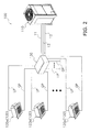
- FIG 2 is a diagram of an entire configuration of the air conditioning system 100.
- the air conditioning system 100 is installed in a building, a factory or the like, and implements air conditioning in a target space.
- the air conditioning system 100 which is an air conditioning system of a refrigerant pipe type, is configured to perform a refrigeration cycle operation of a vapor compression type and performs cooling, heating or the like of the target space.
- the air conditioning system 100 mainly includes a single outdoor unit 110 as a heat source unit, a plurality of indoor units 120 as utilization units, and an intermediate unit 130 configured and arranged to switch flow of refrigerant into the respective indoor units 120. Additionally, the air conditioning system 100 includes a liquid communicating pipe 11, a suction gas communicating pipe 12 and a high-low pressure gas communicating pipe 13 and a plurality of pairs of a liquid pipe LP and a gas pipe GP.
- the liquid communicating pipe 11, the suction gas communicating pipe 12 and the high-low pressure gas communicating pipe 13 connect the outdoor unit 110 and the intermediate unit 130.
- the liquid pipe LP and the gas pipe GP that connect the intermediate unit 130 and the indoor unit 120.
- the air conditioning system 100 is configured to perform the refrigeration cycle operation that the refrigerant encapsulated in a refrigerant circuit is compressed, cooled or condensed, decompressed, heated or evaporated, and then, compressed again. It should be noted that the air conditioning system 100 is of a so-called cooling/heating free type that either a cooling operation or a heating operation is freely selectable in each of the indoor units 120.
- the air conditioning system 100 will be hereinafter explained in detail.
- FIG 3 is a diagram of a refrigerant circuit within the outdoor unit 110.
- the outdoor unit 110 is installed in an outdoor space (e.g., a roof or a veranda of a building) or a basement.
- a variety of machines are disposed within the outdoor unit 110 and are connected through refrigerant pipes, whereby a heat source-side refrigerant circuit RC1 is formed.
- the heat source-side refrigerant circuit RC1 is connected to a gas refrigerant circuit RC3 (to be described) and a liquid refrigerant circuit RC4 (to be described), which are provided within the intermediate unit 130, through the liquid communicating pipe 11, the suction gas communicating pipe 12 and the high-low pressure gas communicating pipe 13.
- the heat source-side refrigerant circuit RC1 is formed by mainly connecting a first gas-side stop valve 21, a second gas-side stop valve 22, a liquid-side stop valve 23, an accumulator 24, a compressor 25, a first channel switch valve 26, a second channel switch valve 27, a third channel switch valve 28, an outdoor heat exchanger 30, a first outdoor expansion valve 34 and a second outdoor expansion valve 35 through a plurality of refrigerant pipes. Additionally, an outdoor fan 33, an outdoor unit controller (not shown in the drawings) and the like are disposed within the outdoor unit 110.
- the first gas-side stop valve 21, the second gas-side stop valve 22 and the liquid-side stop valve 23 are manual valves configured to be opened/closed in a refrigerant filling work, a pump-down work, or the like.
- the first gas-side stop valve 21 is connected at one end to the suction gas communicating pipe 12, and is also connected at the other end to the refrigerant pipe extending to the accumulator 24.
- the second gas-side stop valve 22 is connected at one end to the high-low pressure gas communicating pipe 13, and is also connected at the other end to the refrigerant pipe extending to the second channel switch valve 27.
- the liquid-side stop valve 23 is connected at one end to the liquid communicating pipe 11, and is also connected at the other end to the refrigerant pipe extending to either the first outdoor expansion valve 34 or the second outdoor expansion valve 35.
- the accumulator 24 is a container for temporarily accumulating the refrigerant at low pressure to be sucked into the compressor 25 and performing gas-liquid separation for the refrigerant In the interior of the accumulator 24, the refrigerant in a gas-liquid dual-phase state is separated into the gas refrigerant and the liquid refrigerant.
- the accumulator 24 is disposed between the first gas-side stop valve 21 and the compressor 25.
- the refrigerant pipe extending from the first gas-side stop valve 21 is connected to a refrigerant inlet of the accumulator 24.
- a suction pipe 251 extending to the compressor 25 is connected to a refrigerant outlet of the accumulator 24.
- the compressor 25 has a sealed structure in which a compressor motor is embedded.
- the compressor 25 is a displacement compressor such as a scroll compressor or a rotary compressor. It should be noted that only one compressor 25 is provided in the present embodiment, however, the number of the compressors 25 is not limited to one, and two or more compressors 25 may be connected in parallel.
- the suction pipe 251 is connected to a suction port (not shown in the drawings) of the compressor 25.
- the compressor 25 is configured to suck the refrigerant at low pressure through the suction port, compress the sucked refrigerant, and then discharge the compressed refrigerant through a discharge port (not shown in the drawings).
- a discharge pipe 252 is connected to the discharge port of the compressor 25.
- the first channel switch valve 26, the second channel switch valve 27 and the third channel switch valve 28 are four-way switch valves and are configured to switch the flow of the refrigerant in accordance with conditions (see solid line and broken line in FIG 3 ).
- the discharge pipe 252 or branch pipes extending from the discharge pipe 252 are respectively connected to the refrigerant inlet of each channel switch valve SV Additionally, each channel switch valve SV is configured to block the flow of the refrigerant in one of the refrigerant channels during operation and practically functions as a three-way valve.
- the outdoor heat exchanger 30 is a heat exchanger of a cross-fin type or a micro-channel type.
- the outdoor heat exchanger 30 includes a first heat exchange portion 31 and a second heat exchange portion 32.
- the first heat exchange portion 31 is mounted to an upper position, whereas the second heat exchange portion 32 is mounted to a lower position than the first heat exchange portion 31.
- the first heat exchange portion 31 is connected at one end to the refrigerant pipe that is connected to the third channel switch valve 28, and is also connected at the other end to the refrigerant pipe extending to the first outdoor expansion valve 34.
- the second heat exchange portion 32 is connected at one end to the refrigerant pipe that is connected to the first channel switch valve 26, and is also connected at the other end to the refrigerant pipe extending to the second outdoor expansion valve 35.
- the refrigerant passing through the first heat exchange portion 31 and that passing through the second heat exchange portion 32 are configured to exchange heat with airflow to be generated by the outdoor fan 33.
- the outdoor fan 33 is a propeller fan, for instance, and is configured to be driven in conjunction with an outdoor fan motor (not shown in the drawings).
- an outdoor fan motor not shown in the drawings.
- Each of the first outdoor expansion valve 34 and the second outdoor expansion valve 35 is, for instance, an electric valve that its opening degree is adjustable.
- the first outdoor expansion valve 34 is connected at one end to the refrigerant pipe extending from the first heat exchange portion 31, and is also connected at the other end to the refrigerant pipe extending to the liquid-side stop valve 23.
- the second outdoor expansion valve 35 is connected at one end to the refrigerant pipe extending from the second heat exchange portion 32, and is also connected at the other end to the refrigerant pipe extending to the liquid-side stop valve 23.
- Each of the first outdoor expansion valve 34 and the second outdoor expansion valve 35 is configured to adjust its opening degree in accordance with conditions, and decompress the refrigerant passing through its interior in accordance with its opening degree.
- the outdoor unit controller is a microcomputer composed of a CPU, a memory and the like.
- the outdoor unit controller is configured to send/receive signals to/from indoor unit controllers (to be described) and an intermediate unit controller 132 (to be described) through communication lines (not shown in the drawings).
- the outdoor unit controller is configured to control activation/deactivation and the rotational speed of the compressor 25 and those of the outdoor fan 33 and is also configured to control opening/closing and opening degree adjustment of a variety of valves.
- FIG 4 is a diagram of refrigerant circuits within the indoor units 120 and the intermediate unit 130.
- Each of the indoor units 120 is of a so-called ceiling embedded type or a so-called ceiling suspended type that is installed in a space above the ceiling or the like, or alternatively, is of a wall mounted type that is mounted to the inner wall of an indoor space or the like.
- the air conditioning system 100 of the present embodiment includes the plural indoor units 120. Specifically, 16 sets of indoor units (120a to 120p) are disposed therein.
- a utilization-side refrigerant circuit RC2 is formed in each indoor unit 120.
- an indoor expansion valve 51 and an indoor heat exchanger 52 are provided, and are connected to each other through a refrigerant pipe.
- an indoor fan 53 and the indoor unit controller are disposed within each indoor unit 120.
- the indoor expansion valve 51 is an electric valve that its opening degree is adjustable.
- the indoor expansion valve 51 is connected at one end to a relevant one of the liquid pipes LP, and is also connected at the other end to the refrigerant pipe extending to the indoor heat exchanger 52.
- the indoor expansion valve 51 is configured to decompress the refrigerant passing therethrough in accordance with its opening degree.
- the indoor heat exchanger 52 is a heat exchanger of a cross-fin type or a micro-channel type, for instance, and includes a heat transfer tube (not shown in the drawings).
- the indoor heat exchanger 52 is connected at one end to the refrigerant pipe extending from the indoor expansion valve 51, and is also connected at the other end to a relevant one of the gas pipes GP.
- the refrigerant, flowing into the indoor heat exchanger 52 exchanges heat with airflow to be generated by the indoor fan 53 when passing through the heat transfer tube.
- the indoor fan 53 is, for instance, a cross-flow fan or a sirocco fan.
- the indoor fan 53 is configured to be driven in conjunction with an indoor fan motor (not shown in the drawings).
- an indoor fan motor not shown in the drawings.
- the indoor unit controller is a microcomputer composed of a CPU, a memory and the like.
- the indoor unit controller is configured to receive an instruction inputted by a user through a remote controller (not shown in the drawings) and drive the indoor fan 53 and the indoor expansion valve 51 in response to this instruction. Additionally, the indoor unit controller is connected to the outdoor unit controller and the intermediate unit controller 132 (to be described) through a communication line (not shown in the drawings), and is configured to send/receive signals thereto/therefrom.
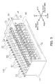
- FIG 5 is a perspective view of the intermediate unit 130.
- FIG 6 is a right side view of the intermediate unit 130.
- FIG 7 is a top view of the intermediate unit 130.
- FIG 8 is a front view of the intermediate unit 130.
- FIG 9 is a rear view of the intermediate unit 130.
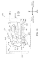
- FIG 10 is a cross-sectional view of FIG 5 taken along line IX-IX.
- the intermediate unit 130 is disposed between the outdoor unit 110 and the respective indoor units 120, and is configured to switch the flow of the refrigerant flowing into the outdoor unit 110 and the flow of the refrigerant flowing into each indoor unit 120.
- the intermediate unit 130 includes a casing 131 made of metal.
- the casing 131 is made in an approximately cubical shape, and a drain pan (not shown in the drawings) is detachably mounted to the bottom of the casing 131.
- the casing 131 mainly accommodates a BS unit assembly 60 and the intermediate unit controller 132.
- FIG 11 is a perspective view of the BS unit assembly 60.
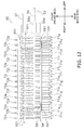
- FIG 12 is a bottom view of the BS unit assembly 60.
- the BS unit assembly 60 is constructed by the combination of a plurality of refrigerant pipes, electric valves and the like.
- the BS unit assembly 60 is conceptually assembled by aggregating a plurality of the BS units 70, each of which is shown in FIG 13 .
- the BS unit assembly 60 includes a plurality of headers (a first header 55, a second header 56, a third header 57 and a fourth header 58) and the BS units 70, the number of which is the same as that of the indoor units 120.
- the BS unit assembly 60 includes 16 sets of the BS units 70a to 70p (see FIG 4 , etc.).
- the first header 55 is connected to and communicated with the high-low pressure gas communicating pipe 13.
- the first header 55 includes a first header filter 55a in the vicinity of its connected part to the high-low pressure gas communicating pipe 13 (see FIG 11 ).
- the first header filter 55a is configured to remove foreign objects contained in the refrigerant passing therethrough.
- the first header 55 is connected approximately perpendicularly to an eighth pipe P8 of each first unit 71 to be described.
- the second header 56 is connected to and communicated with the suction gas communicating pipe 12.
- the second header 56 includes a second header filter 56a in the vicinity of its connected part to the suction gas communicating pipe 12 (see FIG 11 ).
- the second header filter 56a is configured to remove foreign objects contained in the refrigerant passing therethrough. Additionally, the second header 56 is connected approximately perpendicularly to a sixth pipe P6 of each first unit 71 to be described.
- the second header 56 includes first connecting parts 561 located right and left.
- the first connecting parts 561 are connected to second connecting parts 581 (to be described) of the fourth header 58.
- the second header 56 is communicated with the fourth header 58 through these first connecting parts 561 (see FIGS. 12 and 16 ).
- Each first connecting part 561 gently extends upward from the second header 56, then curves and extends downward (see FIGS. 6 and 10 ).
- Each first connecting part 561 thus upwardly extends from the second header 56 in order to form a trap for inhibiting the refrigerant existing in the second header 56 and the refrigerator oil compatibly mixed with the refrigerant from flowing into each first connecting part 561 in a situation such as deactivation of the air conditioning system 100.
- the third header 57 is connected to and communicated with the liquid communicating pipe 11.
- the third header 57 is connected approximately perpendicularly to a first pipe P1 of each liquid communicating unit 73 to be described.
- the fourth header 58 is connected approximately perpendicularly to a ninth pipe P9 of each bypass unit 74 to be described. Additionally, the fourth header 58 includes the second connecting parts 581 located right and left. The second connecting parts 581 are connected to the first connecting parts 561 of the second header 56. The fourth header 58 is communicated with the second header 56 through the second connecting parts 581 (see FIGS. 12 and 16 ).
- the first header 55, the second header 56, the third header 57 and the fourth header 58 extend along the right-and-left direction (horizontal direction).
- the first header 55, the second header 56 and the third header 57 are exposed to the outside via through holes bored in the left lateral surface of the casing 131. Additionally, regarding the positional relation among the headers in the height direction, the first header 55, the fourth header 58, the second header 56 and the third header 57 are aligned from top to bottom in this sequential order (see FIGS. 6 and 10 ).
- the fourth header 58, the first header 55, the second header 56 and the third header 57 are aligned in this sequential order from the back side to the front side (see FIGS. 6 and 10 ).
- first header 55, the second header 56, the third header 57 and the fourth header 58 extend in approximately parallel to each other.
- the BS units 70 are associated with the indoor units 120 on a one-to-one basis.
- the BS unit 70a is associated with the indoor unit 120a
- the BS unit 70b is associated with the indoor unit 120b
- the BS unit 70p is associated with the indoor unit 120p.
- Each BS unit 70 will be explained in detail in "(3) Detailed Explanation of BS Unit 70" to be described.
- the intermediate unit controller 132 is a microcomputer composed of a CPU, a memory and the like.
- the intermediate unit controller 132 is configured to receive a signal from either each indoor unit controller or the outdoor unit controller through the communication line and control opening/closing of each of a first electric valve Ev1 (to be described), a second electric valve Ev2 (to be described) and a third electric valve Ev3 (to be described) in accordance with this signal.
- FIG 13 is an enlarged view of each BS unit 70 shown in a region A of FIG 11 .
- Each BS unit 70 is disposed between the outdoor unit 110 and its relevant indoor unit 120, and is configured and arranged to switch the flow of the refrigerant.
- Each BS unit 70 is mainly composed of the first unit 71 shown in FIG 14 and a second unit 72 shown in FIG 15 .
- FIG 14 is a perspective view of the first unit 71.
- the first unit 71 is a unit for composing the gas refrigerant circuit RC3 within each BS unit 70.
- the first unit 71 is connected to the high-low pressure gas communicating pipe 13 through the first header 55, is connected to the suction gas communicating pipe 12 through the second header 56, and is connected to its relevant utilization-side refrigerant circuit RC2 through its relevant gas pipe GP.
- the first unit 71 is mainly configured to cause the gas refrigerant to flow between either the high-low pressure gas communicating pipe 13 or the suction gas communicating pipe 12 and its relevant utilization-side refrigerant circuit RC2.
- the first unit 71 includes the first electric valve Ev1 and the second electric valve Ev2 as switch valves. Additionally, the first unit 71 includes a first filter Fl1. Moreover, the first unit 71 includes a third pipe P3, a fourth pipe P4, a fifth pipe P5, the sixth pipe P6, a seventh pipe P7 and the eighth pipe P8 as refrigerant pipes. It should be noted that in the present embodiment, not electro-magnetic valves but electric valves (the first electric valve Ev1 and the second electric valve Ev2) are employed as switch valves in order to inhibit sound of the refrigerant passing through the interior of the first unit 71.
- the first unit 71 is mainly divided into a first part R1 (corresponding to "first refrigerant pipe” described in claims), a second part R2 (corresponding to “second refrigerant pipe” described in claims) and a third part R3 (corresponding to "third refrigerant pipe” described in claims).
- the first unit 71 is constructed by connecting the first part R1, the second part R2 and the third part R3 through a connecting portion J1.
- the first part R1 is connected at one end to the suction gas communicating pipe 12 through the second header 56, and is also connected at the other end to the second part R2 and the third part R3 through the connecting portion J1.
- the first part R1 is a part including the first electric valve Ev1, the fifth pipe P5 and the sixth pipe P6. It should be noted that from another perspective of view, the first part R1 can be regarded as a single refrigerant pipe connected to the suction gas communicating pipe 12 (i.e., the first part R1 corresponds to "first refrigerant pipe" described in claims).
- the first electric valve Ev1 is an electric valve that its opening degree is adjustable, for instance, and is configured to switch the flow of the refrigerant by allowing or blocking passage of the refrigerant in accordance with its opening degree.
- the first electric valve Ev1 is made in an approximately columnar shape, and is disposed in a posture that its lengthwise direction is oriented in the up-and-down direction (vertical direction).
- the first electric valve Ev1 is connected at one end to the fifth pipe P5, and is also connected at the other end to the sixth pipe P6. It should be noted that in a plan view, the first electric valve Ev1 is located on a straight line on which a bottom part B1 (to be described) of the fourth pipe P4 and the fifth pipe P5 extend (see FIG 7 , etc.).
- the fifth pipe P5 is connected at one end to the connecting portion J1, and is also connected at the other end to the first electric valve Ev1. More specifically, the fifth pipe P5 forwardly (horizontally) extends from the one end (its connecting-part to the connecting portion J1) and is connected at the other end to the first electric valve Ev1 (see FIGS. 13 and 14 ).
- the sixth pipe P6 is connected at one end to the second header 56, and is also connected at the other end to the first electric valve Ev1. More specifically, the sixth pipe P6 gently extends upward from the one end (i.e., its connecting-part to the second header 56), then curves and extends downward, further curves and extends forward (horizontally), yet further curves and extends upward (vertically), and is connected at the other end to the first electric valve Ev1 (see FIGS. 6 , 10 , 13 and 14 ).
- the sixth pipe P6 thus upwardly extends partially from its connecting-part to the second header 56 in order to form a trap for inhibiting the refrigerant existing in the second header 56 and the refrigerator oil compatibly mixed with the refrigerant from flowing into the sixth pipe P6 in a situation such as deactivation of the air conditioning system 100. It should be noted that the sixth pipe P6 is connected approximately perpendicularly to the second header 56.
- the second part R2 is connected at one end to the high-low pressure gas communicating pipe 13 through the first header 55, and is also connected at the other end to the first part R1 and the third part R3 through the connecting portion J1.
- the second part R2 is a part including the second electric valve Ev2, the seventh pipe P7 and the eighth pipe P8. It should be noted that from another perspective of view, the second part R2 can be regarded as a single refrigerant pipe connected to the high-low pressure gas communicating pipe 13 (i.e., the second part R2 corresponds to "second refrigerant pipe" described in claims).
- the second electric valve Ev2 is, for instance, an electric valve that its opening degree is adjustable. Specifically, the second electric valve Ev2 is formed a minute channel rp in its interior, and enables the refrigerant to flow through the minute channel rp even when its opening degree is set to be the minimum degree (lowest degree). Thus, the second electric valve Ev2 is configured not to be completely closed even when its opening degree is minimized. As shown in FIG 14 (a drive part of the second electric valve Ev2 is not shown in FIG 14 ), the second electric valve Ev2 is made in an approximately columnar shape, and is disposed in a posture that its lengthwise direction is oriented in the up-and-down direction (vertical direction).
- the second electric valve Ev2 is connected at one end to the seventh pipe P7, and is also connected at the other end to the eighth pipe P8. It should be noted that as shown in FIG 10 and the like, the second electric valve Ev2 is disposed rearward of the first electric valve Ev1. Also, the second electric valve Ev2 is disposed above (in a higher position than) the first electric valve Ev1. It should be noted that the second electric valve Ev2 will be explained in detail in "(6) Detailed Explanation of Second Electric Valve Ev2" to be described.
- the seventh pipe P7 is connected at one end to the connecting portion J1 and is also connected at the other end to the second electric valve Ev2. More specifically, the seventh pipe P7 upwardly (vertically) extends from the one end (i.e., its connecting-part to the connecting portion J1) and is connected at the other end to the second electric valve Ev2 (see FIGS. 13 and 14 ).
- the eighth pipe P8 is connected at one end to the second electric valve Ev2, and is also connected at the other end to the first header 55. More specifically, the eighth pipe P8 extends rearward (horizontally) from the one end (i.e., its connecting-part to the second electric valve Ev2) and is connected at the other end approximately perpendicularly to the first header 55 (see FIGS. 13 and 14 ).
- the third part R3 is connected at one end to its relevant gas pipe GP, and is also connected at the other end to the first part R1 and the second part R2 through the connecting portion J1.
- the third part R3 is a part including the first filter Fl1, the third pipe P3, the fourth pipe P4 and the connecting portion J1.
- the third part R3 can be regarded as a single refrigerant pipe connected to its relevant gas pipe GP (i.e., the third part R3 corresponds to "third refrigerant pipe" described in claims).
- the first filter Fl1 is for removing foreign objects contained in the refrigerant passing therethrough. As shown in FIG 14 , the first filter Fl1 is made in an approximately columnar shape, and is disposed in a posture that its lengthwise direction is oriented in the back-and-forth direction (horizontal direction). The first filter Fl1 is connected at one end to the third pipe P3, and is also connected at the other end to the fourth pipe P4.
- the third pipe P3 is connected at one end to its relevant gas pipe GP, and is also connected at the other end to the first filter Fl1. It should be noted that the one end of the third pipe P3 is exposed to the outside from the back side of the casing 131 (see FIG 6 , FIG 10 , etc.).
- the fourth pipe P4 is connected at one end to the first filter Fl1, and is also connected at the other end to the connecting portion J1. More specifically, the fourth pipe P4 extends from the one end (its connecting-part to the first filter Fl1) to the front side in an obliquely downwardly tilting posture, then horizontally (forwardly) extends, and is connected at the other end to the connecting portion J1 (see FIG 10 , etc.).
- the connecting portion J1 is a pipe coupler for refrigerant pipes configured and arranged to have an inverted T shape.
- the connecting portion J1 is designed to enable three pipes to be connected thereto through openings bored upward, forward and backward.
- the connecting portion J1 is connected to the other end of the fourth pipe P4 by flare fittings, brazing or the like.
- the third part R3 is connected to the fifth pipe P5 of the first part R1 and the seventh pipe P7 of the second part R2 through the connecting portion J1.
- FIG 15 is a perspective view of the second unit 72.
- the second unit 72 is mainly divided into the liquid communicating unit 73 (corresponding to "fourth refrigerant pipe” described in claims) and the bypass unit 74.
- the liquid communicating unit 73 is a unit for composing the liquid refrigerant circuit RC4 within each BS unit 70.
- the liquid communicating unit 73 is connected at one end to the liquid communicating pipe 11 through the third header 57, and is also connected at the other end to its relevant liquid pipe LP.
- the liquid communicating unit 73 is a refrigerant pipe unit that mainly causes liquid refrigerant to flow between the liquid communicating pipe 11 and its relevant liquid pipe LP.
- the liquid communicating unit 73 can be regarded as a single refrigerant pipe connected at one end to the liquid communicating pipe 11 and is connected at the other end to its relevant liquid pipe LP (i.e., the liquid communicating unit 73 corresponds to "fourth refrigerant pipe" described in claims).
- the liquid communicating unit 73 mainly includes a supercooling heat exchange portion 59 and the first pipe P1 and the second pipe P2 as refrigerant pipes.
- the supercooling heat exchange portion 59 is, for instance, a heat exchanger of a two-nested-pipe type.
- the supercooling heat exchange portion 59 is made in an approximately tubular shape, and is formed a first channel 591 and a second channel 592 in the interior thereof. More specifically, the supercooling heat exchange portion 59 has a structure that enables heat exchange between the refrigerant flowing through the first channel 591 and the refrigerant flowing through the second channel 592.
- the first channel 591 is connected at one end to the first pipe P1, and is also connected at the other end to the second pipe P2.
- the second channel 592 is connected at one end to the ninth pipe P9, and is also connected at the other end to a tenth pipe P10.
- the supercooling heat exchange portion 59 is disposed in a posture that it extends along the back-and-forth direction (horizontal direction). It should be noted that in the BS unit assembly 60, each supercooling heat exchange portion 59 extends in approximately parallel to each third pipe P3, each fourth pipe P4 and the like.
- the first pipe P1 is connected at one end to the third header 57, and is also connected at the other end to the first channel 591 of the supercooling heat exchange portion 59. Specifically, the first pipe P1 upwardly (vertically) extends from the one end (i.e., its connecting-part to the third header 57) and is connected at the other end to the supercooling heat exchange portion 59 (see FIGS. 13 and 15 ). It should be noted that the first pipe P1 is connected approximately perpendicularly to the third header 57.
- the second pipe P2 is connected at one end to the first channel 591 of the supercooling heat exchange portion 59, and is also connected at the other end to its relevant liquid pipe LP. Specifically, the second pipe P2 extends rearward (horizontally) from the one end (i.e., its connecting-part to the supercooling heat exchange portion 59), then curves and extends upward (vertically), and further curves and extends rearward (horizontally) (see FIGS. 13 and 15 ). It should be noted that the other end of the second pipe P2 is exposed to the outside from the back side of the casing 131 (see FIG 6 , FIG 10 , etc.).
- the bypass unit 74 is a unit for bypassing the refrigerant from the fourth header 58 to the liquid communicating unit 73. Specifically, the bypass unit 74 is connected at one end to the fourth header 58, and is also connected at the other end to the first pipe P1 of the liquid communicating unit 73. The bypass unit 74 bypasses the gas refrigerant, which has passed through the sixth pipe P6 of the first unit 71 and has then flown into the fourth header 58 through the second header 56, to the first pipe P1 of the liquid communicating unit 73.
- the bypass unit 74 mainly includes the third electric valve Ev3, a second filter F12, and ninth, tenth, eleventh and twelfth pipes P9, P10, P11 and P12 as refrigerant pipes.
- the third electric valve Ev3 is an electric valve that its opening degree is adjustable, for instance, and is configured to switch the flow of the refrigerant by allowing or blocking passage of the refrigerant in accordance with its opening degree.
- the third electric valve Ev3 is made in an approximately columnar shape, and is disposed in a posture that its lengthwise direction is oriented in the up-and-down direction (vertical direction).
- the third electric valve Ev3 is connected at one end to the tenth pipe P10, and is also connected at the other end to the eleventh pipe P11.
- the second filter F12 is for removing foreign objects contained in the refrigerant passing therethrough. As shown in FIG 15 , the second filter F12 is made in an approximately columnar shape, and is disposed in a posture that its lengthwise direction is oriented in the up-and-down direction (vertical direction). Specifically, the second filter F12 is connected at one end to the eleventh pipe P11, and is also connected at the other end to the twelfth pipe P12.
- the ninth pipe P9 is connected at one end to the fourth header 58, and is also connected at the other end to the second channel 592 of the supercooling heat exchange portion 59. Specifically, the ninth pipe P9 upwardly (vertically) extends from the one end (i.e., its connecting-part to the fourth header 58), curves and extends forward (horizontally), and is connected to the supercooling heat exchange portion 59 (see FIGS. 13 and 15 ). It should be noted that the ninth pipe P9 is connected approximately perpendicularly to the fourth header 58.
- the tenth pipe P10 is connected at one end to the second channel 592 of the supercooling heat exchange portion 59, and is also connected at the other end to the third electric valve Ev3. Specifically, the tenth pipe P10 upwardly (vertically) extends from the one end (i.e., its connecting-part to the supercooling heat exchange portion 59), and is connected at the other end to the third electric valve Ev3 (see FIGS. 13 and 15 ).
- the eleventh pipe P11 is connected at one end to the third electric valve Ev3, and is also connected at the other end to the second filter F12. Specifically, the eleventh pipe P11 downwardly (vertically) extends from its part connected to the third electric valve Ev3, and is connected at the other end to the second filter F12 (see FIGS. 13 and 15 ).
- the twelfth pipe P12 is connected at one end to the second filter F12, and is also connected at the other end to the first pipe P1. Specifically, the twelfth pipe P 12 downwardly (vertically) extends from the one end (i.e., its connecting-part to the second filter F12), curves and extends rearward (horizontally), and is connected at the other end to the first pipe P1 (see FIGS. 13 and 15 ).
- Refrigerant flow during operation of the air conditioning system 100 will be hereinafter explained for various conditions in which the indoor units 120a and 120b are assumed to be under operation.
- the other indoor units 120 (120c to 120p) are assumed to be under deactivation to make explanation simple. Due to this, the indoor expansion valves 51 in the indoor units 120 except for the indoor units 120a and 120b are assumed to be fully closed, and the first electric valves Ev1 and the third electric valves Ev3 in the BS units 70 except for the BS units 70a and 70b (i.e., BS units 70c to 70p) are assumed to be fully closed. Additionally, the second electric valves Ev2 in the BS units 70c to 70p are assumed to be opened at the minimum opening degree.
- the first electric valve Ev1 is configured to be fully opened and the second electric valve Ev2 is configured to be opened at the minimum opening degree.
- the indoor expansion valve 51 in each of the indoor units 120a and 120b is configured to be opened at an appropriate opening degree, and the first outdoor expansion valve 34 and the second outdoor expansion valve 35 are configured to be fully opened.
- the high-pressure gas refrigerant produced by compression of the compressor 25 flows into the outdoor heat exchanger 30 through the discharge pipe 252, the first channel switch valve 26, the third channel switch valve 28 and the like, and condenses therein.
- the refrigerant, which has condensed in the outdoor heat exchanger 30, passes through the liquid-side stop valve 23 and the like, and flows into the liquid communicating pipe 11.
- the refrigerant, which has flown into the liquid communicating pipe 11, reaches the third header 57 of the intermediate unit 130 in due course, and flows into the first pipe P1 of the BS unit 70a or 70b (the second unit 72a or 72b).
- the refrigerant which has flown into the first pipe P1, flows through the second pipe P2, the relevant liquid pipe LP and the like, reaches the indoor unit 120a or 120b, flows into the indoor expansion valve 51, and is decompressed therein.
- the decompressed refrigerant flows into each indoor heat exchanger 52 and evaporates therein.
- the evaporated refrigerant flows into the third pipe P3 of the BS unit 70a or 70b (the first unit 71a or 71b) through the gas pipe GP
- the refrigerant which has flown into the third pipe P3, flows through the fourth pipe P4, the fifth pipe P5, the sixth pipe P6 and the like, and reaches the second header 56.
- the indoor unit 120a or 120b is deactivated due to a thermo-off function or the like, the refrigerant existing in the second part R2 (the eighth pipe P8 and the seventh pipe P7) is bypassed to the first part R1 (the fifth pipe P5 and the like) through the minute channel rp of the second electric valve Ev2 and the like.
- the first electric valve Ev1 is configured to be fully closed, whereas the second electric valve Ev2 is configured to be fully opened.
- the indoor expansion valve 51 in each of the indoor units 120a and 120b is configured to be fully opened, and each of the first outdoor expansion valve 34 and the second outdoor expansion valve 35 is configured to be opened at an appropriate opening degree.
- the high-pressure gas refrigerant produced by compression of the compressor 25 flows into the high-low pressure gas communicating pipe 13 through the discharge pipe 252, the second channel switch valve 27 and the like.
- the refrigerant, which has flown into the high-low pressure gas communicating pipe 13, reaches the first header 55 of the intermediate unit 130 in due course.
- the refrigerant, which has reached the first header 55 flows into the eighth pipe P8 of the BS unit 70a or 70b (the first unit 71a or 71b) and then flows into the gas pipe GP through the seventh pipe P7, the fourth pipe P4, the third pipe P3 and the like.
- the refrigerant which has flown into the gas pipe GP, reaches the indoor unit 120a or 120b, flows into each indoor heat exchanger 52, and condenses therein.
- the condensed refrigerant flows into the second pipe P2 of the BS unit 70a or 70b (the second unit 72a or 72b) through the liquid pipe LP.
- the refrigerant which has flown into the second pipe P2, reaches the third header 57 through the first pipe P1 and the like.
- the refrigerant which has flown into the outdoor unit 110, is decompressed in the first outdoor expansion valve 34 or the second outdoor expansion valve 35.
- the decompressed refrigerant flows into the outdoor heat exchanger 30 and evaporates therein while passing through the outdoor heat exchanger 30.
- the evaporated refrigerant is sucked into the compressor 25 through the first channel switch valve 26 or the third channel switch valve 28 and the like.
- one BS unit 70 associated with one of the indoor units 120 performing a cooling operation
- the first electric valve Ev1 is configured to be fully opened
- the second electric valve Ev2 is configured to be opened at the minimum opening degree
- the third electric valve Ev3 is configured to be opened at an appropriate opening degree.
- the indoor expansion valve 51 is configured to be opened at an appropriate opening degree.
- the other of the BS units 70a and 70b (hereinafter referred to as “the other BS unit 70") associated with the other of the indoor units 120 performing a heating operation (hereinafter referred to as “the other indoor unit 120")
- the first electric valve Ev1 is configured to be fully closed
- the second electric valve Ev2 is configured to be fully opened.
- the indoor expansion valve 51 is configured to be fully opened.
- each of the first outdoor expansion valve 34 and the second outdoor expansion valve 35 is configured to be opened at an appropriate opening degree.
- the high-pressure gas refrigerant produced by compression of the compressor 25 flows into the high-low pressure gas communicating pipe 13 through the discharge pipe 252, the second channel switch valve 27 and the like.
- the refrigerant, which has flown into the high-low pressure gas communicating pipe 13, reaches the first header 55 of the intermediate unit 130 in due course.
- the refrigerant, which has reached the first header 55 flows into the first unit 71 in the other BS unit 70, and flows into the gas pipe GP through the eighth pipe P8, the seventh pipe P7, the fourth pipe P4, the third pipe P3 and the like.
- the refrigerant which has flown into the relevant gas pipe GP, reaches the other indoor unit 120, flows into the indoor heat exchanger 52, and condenses therein.
- the condensed refrigerant flows into the second pipe P2 of the liquid communicating unit 73 in the other BS unit 70 through the liquid pipe LP.
- the refrigerant, which has flown into the second pipe P2 reaches the third header 57 through the first pipe P1 and the like.
- the refrigerant which has reached the third header 57, reaches the liquid communicating unit 73 in the one BS unit 70 and flows into the first pipe P1.
- the refrigerant, which has flown into the first pipe P1 passes through the first channel 591 of the supercooling heat exchange portion 59 and reaches the one indoor unit 120 through the second pipe P2 and the liquid pipe LP.
- the refrigerant which has reached the one indoor unit 120, flows into the indoor expansion valve 51 and is decompressed therein.
- the decompressed refrigerant flows into the indoor heat exchanger 52 and evaporates therein.
- the evaporated refrigerant reaches the first unit 71 of the one BS unit 70 through the gas pipe GP and flows into the third pipe P3.
- the refrigerant, which has flown into the third pipe P3, flows through the fourth pipe P4, the fifth pipe P5, the sixth pipe P6 and the like, and reaches the second header 56.
- Part of the refrigerant having reached the second header 56 flows into the outdoor unit 110 through the suction gas communicating pipe 12 and is sucked into the compressor 25.
- the rest of the refrigerant having reached the second header 56 flows into the fourth header 58 through the pairs of the first connecting part 561 and the second connecting part 581.
- the pairs of the first connecting part 561 and the second connecting part 581 play a role of connecting pipes that connect the second header 56 and the fourth header 58 and feed the refrigerant within the second header 56 to the fourth header 58.
- the refrigerant which has passed through the second channel 592, flows through the tenth pipe P10, the eleventh pipe P11, the twelfth pipe P12 and the like, and joins the refrigerant flowing through the first pipe P1.
- the refrigerant existing in the second part R2 (the eighth pipe P8 and the seventh pipe P7) of the one BS unit 70, is bypassed to the first part R1 (the fifth pipe P5 and the like) through the minute channel rp of the second electric valve Ev2 and the like.
- FIG 16 is an exploded view of the BS unit assembly 60.
- the intermediate unit 130 is mainly manufactured by combining separately fabricated components such as the casing 131, the intermediate unit controller 132 and the BS unit assembly 60 including the plural BS units 70, in a production line.
- the BS unit assembly 60 is mounted onto the bottom side of the casing 131 manufactured by sheet metal working, and is suitably fixed thereto by screws and the like.
- the intermediate unit controller 132 is accommodated in the casing 131, and wiring connection between the intermediate unit controller 132 and the first, second and third electric valves Ev1, Ev2 and Ev3 and the like are performed.
- a drain pan and the like are mounted to the casing 131, and then, the top side and the front side part of the casing 131 are fixed by screws and the like.
- the BS unit assembly 60 is fabricated by combining a first assembly 81 and a second assembly 82 and then by fixing the combined first and second assemblies 81 and 82 with a fixing tool 601 (see FIGS. 6 and 12 ).
- the first assembly 81 is assembled by integrating the plural first units 71 (71a to 71p).
- the second assembly 82 is assembled by integrating the plural second units 72 (72a to 72p).
- FIG 17 is a cross-sectional view of a main part of the second electric valve Ev2 (without illustration of the drive part 90).
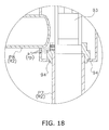
- FIG 18 is an enlarged view of a region B of FIG 17 .
- the second electric valve Ev2 is a so-called gear type electric valve, and is configured to transmit an output of a motor (not shown in the drawings) embedded in the drive part 90 to a valve element 93 through a pinion, a gear and the like so as to drive the valve element 93 up and down.
- the second electric valve Ev2 includes the drive part 90 (see FIGS. 6 and 10 ) and a valve body 91 to which the drive part 90 is fixed.
- the valve body 91 accommodates an output shaft 92, the valve element 93 and a valve seat 94 in its interior.
- the output shaft 92 is integrally constructed with the gear (not shown in the drawings) engaged with the pinion fixed to a shaft of the motor.
- the output shaft 92 is configured to be, in conjunction with driving of the motor, rotated and be moved up and down.
- the valve element 93 is connected to the output shaft 92, and is configured to be elevated or lowered in conjunction with movement of the output shaft 92. It should be noted that when the valve element 93 is lowered most, the second electric valve Ev2 is configured to be opened at the minimum opening degree.
- the valve seat 94 is shaped such that the valve element 93 is fitted thereto. As shown in FIG 18 , a plurality of slits (grooves) s1 is formed in the valve seat 94 whereby the minute channel rp is formed in the second electric valve Ev2. In other words, when the second electric valve Ev2 is opened at the minimum opening degree, the refrigerant existing within its relevant eighth pipe P8 flow into its relevant seventh pipe P7 through the slits s1.
- each second electric valve Ev2 when each second electric valve Ev2 is opened at the minimum opening degree, formation of a liquid seal circuit is inhibited in its relevant utilization-side refrigerant circuit RC2 and its relevant gas refrigerant circuit RC3. Additionally, when each second electric valve Ev2 is opened at the minimum opening degree, the refrigerant and the refrigeration lubricant, existing in the high-low pressure gas communicating pipe 13, its relevant eighth pipe P8 and the like, are also bypassed through the minute channel rp, and are thereby unlikely to be accumulated therein.
- the minute channel rp is formed in the second electric valve Ev2.
- the minute channel rp is configured and arranged to enable the refrigerant to flow through the minute channel rp even when the opening degree of the second electric valve Ev2 is set to be the lowest degree.
- each BS unit 70 and the intermediate unit 130 can be constructed in compact size.
- the volume of the refrigerant existing within the high-low pressure gas communicating pipe 13 is larger than that of the refrigerant existing within the suction gas communicating pipe 12. Also, the refrigerant is likely to be accumulated in the high-low pressure gas communicating pipe 13. However, with the minute channel rp formed in the second electric valve Ev2, the refrigerant existing within the high-low pressure gas communicating pipe 13 and the refrigeration lubricant compatibly mixed with the refrigerant are led to the interior of each BS unit 70 through the minute channel rp, and are unlikely to be accumulated in the high-low pressure gas communicating pipe 13.
- the slits s1 as the minute channel rp are formed in the valve seat 94 of the second electric valve Ev2.
- the minute channel rp of the second electric valve Ev2 corresponds to the slits s1 formed in the valve seat 94.
- the air conditioning system 100 includes the intermediate unit 130 and the BS units 70, each of which is not required to be provided with a constituent element (e.g., bypass pipe) for inhibiting liquid sealing and is thus compactly constructed by that much.
- a constituent element e.g., bypass pipe
- the intermediate unit 130 and the BS units 70 are easily installed even in a small and narrow space. Consequently, easiness in installation of the air conditioning system 100 is enhanced.
- the air conditioning system 100 is designed to include a single set of the outdoor unit 110.
- the number of sets of the outdoor units 110 is not limited to the above, and may be plural.
- the air conditioning system 100 is designed to include 16 sets of the indoor units 120.
- the number of sets of the indoor units 120 is not limited to the above, and may be any arbitrary number.
- the intermediate unit 130 (the BS unit assembly 60) is designed to include 16 sets of the BS units 70.
- the number of sets of the BS units 70 is not limited to the above, and may be any arbitrary number.
- the number of sets of the BS units 70 disposed in the intermediate unit 130 (the BS unit assembly 60) may be four, six or eight, and alternatively, may be twenty-four.
- the first units 71 and the second units 72 are alternately aligned in the horizontal direction.
- alignment of the first units 71 and the second units 72 is not limited to the above.
- the first units 71 and the second units 72 may be alternately disposed in vertical alignment.
- the BS units 70 are accommodated in the casing 131 in the state of being aggregated as the BS unit assembly 60.
- the construction to accommodate the BS units 70 in the casing 131 is not limited to the above.
- Each of the BS units 70 may be accommodated in a separate casing without being aggregated with the other BS units 70 as the BS unit assembly 60.
- each second electric valve Ev2 has been used as each second electric valve Ev2.
- each second electric valve Ev2 is not limited to this, and may be of another type as long as a minute channel is formed therein.
- a so-called direct acting electro-magnetic valve may be employed as each second electric valve Ev2.
- the minute channel rp formed in the second electric valve Ev2 is made in the aspect shown in FIG 18 .
- the minute channel rp is not limited to this, and may be formed as a minute channel rp' shown in FIG 19 .
- the minute channel rp' is formed by forming a communicating hole h1 in the valve seat 94 of each second electric valve Ev2 instead of forming the slits s1.
- each second electric valve Ev2 which is formed the communicating hole h1 as the minute channel rp'
- the refrigerant existing within its relevant eighth pipe P8 flows into its relevant seventh pipe P7 through the communicating hole h1.
- the minute channel rp' is the communicating hole h1 formed in the valve seat 94. Accordingly, the minute channel can be formed with the simple construction.
- the minute channel rp is formed in the second electric valve Ev2.
- the minute channel rp may be formed in not the second electric valve Ev2 but the first electric valve Ev1.
- the minute channel rp may be formed in both the second electric valve Ev2 and the first electric valve Ev1.
- the present invention can be utilized for a refrigerant channel switching unit configured to switch flow of refrigerant and a refrigeration apparatus including the same.
Landscapes
- Engineering & Computer Science (AREA)
- General Engineering & Computer Science (AREA)
- Mechanical Engineering (AREA)
- Chemical & Material Sciences (AREA)
- Combustion & Propulsion (AREA)
- Physics & Mathematics (AREA)
- Thermal Sciences (AREA)
- Other Air-Conditioning Systems (AREA)
- Multiple-Way Valves (AREA)
- Analytical Chemistry (AREA)
- Power Engineering (AREA)
- Compression-Type Refrigeration Machines With Reversible Cycles (AREA)
Abstract
Description
- The present invention relates to a refrigerant channel switching unit configured and arranged to switch flow of refrigerant and a refrigeration apparatus including the same.
- There has been so far a refrigeration apparatus including a heat source unit, a utilization unit and a refrigerant channel switching unit that is disposed between the heat source unit and the utilization unit and is configured and arranged to switch flow of refrigerant. For example, an air conditioning system disclosed in PTL 1 (Japan Laid-open Patent Application Publication No.
2008-39276 - Now,
FIG 1 schematically shows a refrigerant circuit of a refrigerantchannel switching unit 1 that is an example of a conventional refrigerant channel switching unit. The refrigerantchannel switching unit 1 includes a switch valve 4 and a switch valve 5 connected to arefrigerant pipe 3 extending to a utilization unit 2. The switch valves 4 and 5 are provided for switching the flow of the refrigerant. In general, not electro-magnetic valves but electric valves are employed as the switch valves 4 and 5 in order to inhibit refrigerant running sound. - The electric valve is, unlike the electro-magnetic valve, configured not to be opened due to its construction even when back pressure acts thereon in a completely closed state. In consideration of this, the conventional refrigerant channel switching unit has been so far generally provided with a separate bypass circuit for letting off the refrigerant in order to avoid degradation in safety attributed to formation of a liquid seal circuit. In the refrigerant
channel switching unit 1,capillary tubes 6 and 7 are provided and a bypass circuit 8 and a bypass circuit 9 are formed in order to prevent therefrigerant pipe 3 from becoming a liquid seal circuit. - On the other hand, the refrigerant channel switching unit is generally installed in a small and narrow space such as a space above the ceiling. Hence, the refrigerant channel switching unit is desired to be compactly constructed. However, the conventional refrigerant channel switching unit has been required to reliably have a space for installing the bypass circuit as described above. This has constrained compactness in size of the conventional refrigerant channel switching unit.
- In view of the above, it is an object of the present invention to provide a refrigerant channel switching unit and a refrigeration apparatus, each of which inhibits refrigerant running sound and is good in compactness and safety.
- A refrigerant channel switching unit according to a first aspect of the present invention is disposed between a heat source unit and a utilization unit and is configured and arranged to switch flow of refrigerant in a refrigerant circuit formed by the heat source unit and the utilization unit. The refrigerant channel switching unit configured and arranged to include a first refrigerant pipe, a second refrigerant pipe, a third refrigerant pipe, a fourth refrigerant pipe, a first electric valve and a second electric valve. The first refrigerant pipe is configured and arranged to be connected to a suction gas communicating pipe. The suction gas communicating pipe is configured and arranged to extend from the heat source unit. The second refrigerant pipe is configured and arranged to be connected to a high-low pressure gas communicating pipe. The high-low pressure gas communicating pipe is configured and arranged to extend from the heat source unit. The third refrigerant pipe is configured and arranged to be connected to the first refrigerant pipe, the second refrigerant pipe and a gas pipe. The gas pipe configured and arranged to extend to the utilization unit. The fourth refrigerant pipe is configured and arranged to be connected at one end to a liquid communicating pipe. The liquid communicating pipe is configured and arranged to extend from the heat source unit. The fourth refrigerant pipe is configured and arranged to be connected at the other end to a liquid pipe. The liquid pipe is configured and arranged to extend to the utilization unit. The first electric valve is configured and arranged to be mounted to the first refrigerant pipe. The second electric valve is configured and arranged to be mounted to the second refrigerant pipe. A minute channel is formed in the first electric valve or the second electric valve. The minute channel is configured and arranged to enable the refrigerant to flow through the minute channel even when an opening degree of the first electric valve or the second electric valve is set to be the lowest degree.
- In the refrigerant channel switching unit according to the first aspect of the present invention, refrigerant running sound is inhibited, safety is ensured, and compactness in size is enhanced. There is a possibility that the electric valves are fully closed and a liquid seal circuit is formed in such as a refrigerant channel switching unit, which is not provided with a bypass circuit; which includes commonly used electric valves that are not configured to be formed a minute channel, instead of the first and second electric valves; and which is configured to perform a control of regulating the opening degree of each electric valve in accordance with a condition so as to form a bypass channel for refrigerant.. In the refrigerant channel switching unit according to the first aspect of the present invention, the minute channel is formed in the first electric valve or the second electric valve configured and arranged to enable the refrigerant to flow through the minute channel even when the opening degree thereof is set to be the lowest degree. With the construction and configuration, formation of a liquid seal circuit within the refrigerant circuit is inhibited without separately providing a bypass circuit for inhibiting liquid sealing. Thus, even when electric valves are employed as switch valves, formation of a liquid seal circuit is inhibited, and simultaneously, compactness in size is promoted. Consequently, refrigerant running sound is inhibited, safety is ensured, and compactness in size is enhanced.
- A refrigerant channel switching unit according to a second aspect of the present invention relates to the refrigerant channel switching unit according to the first aspect, and wherein the minute channel is formed in the second electric valve.
- In the refrigerant channel switching unit according to the second aspect of the present invention, the minute channel is formed in the second electric valve. Accordingly, safety is further ensured.
- Specifically, when the gas refrigerant at high pressure flows through the high-low pressure gas communicating pipe, the volume of the refrigerant existing within the high-low pressure gas communicating pipe is larger than that of the refrigerant existing within the suction gas communicating pipe. Hence, the refrigerant is likely to be accumulated within the high-low pressure gas communicating pipe. However, with the minute channel formed in the second electric valve, the refrigerant existing within the high-low pressure gas communicating pipe and a refrigeration lubricant compatibly mixed with the refrigerant are led to the interior of the refrigerant channel switching unit through the minute channel. Thus, the refrigerant and the refrigeration lubricant are unlikely to be accumulated in the high-low pressure gas communicating pipe. Consequently, safety is further ensured.
- A refrigerant channel switching unit according to a third aspect of the present invention relates to the refrigerant channel switching unit according to the first or second aspect, and wherein the minute channel is a groove formed in a valve seat.
- In the refrigerant channel switching unit according to the third aspect of the present invention, the minute channel is a groove formed in a valve seat. Thus, the minute channel is formed with the simple construction. Consequently, increase in cost is inhibited.
- A refrigerant channel switching unit according to a fourth aspect of the present invention relates to the refrigerant channel switching unit according to the first or second aspect, and wherein the minute channel is a hole formed in a valve seat.
- In the refrigerant channel switching unit according to the fourth aspect of the present invention, the minute channel is a hole formed in a valve seat. Thus, the minute channel is formed with the simple construction. Consequently, increase in cost is inhibited.
- A refrigeration apparatus according to a fifth aspect of the present invention includes a heat source unit, a utilization unit, a suction gas communicating pipe, a high-low pressure gas communicating pipe, a liquid communicating pipe, a gas pipe, a liquid pipe and the refrigerant channel switching unit according to any of the first to fourth aspects. The heat source unit and the utilization unit is configured and arranged to form a refrigerantcircuit. The suction gas communicating pipe, the high-low pressure gas communicating pipe and the liquid communicating pipe are configured and arranged to be connected to the heat source unit. The gas pipe and the liquid pipe are configured and arranged to be connected to the utilization unit.
- The refrigeration apparatus according to the fifth aspect of the present invention includes the refrigerant channel switching unit according to any of the first to fourth aspects. With this construction, refrigerant running sound is inhibited, safety of the refrigeration apparatus is ensured, and easiness in installation is enhanced.
- In the refrigerant channel switching unit according to the first aspect of the present invention, even when electric valves are employed as switch valves, formation of a liquid seal circuit is inhibited, and simultaneously, compactness in size is promoted. Therefore, refrigerant running sound is inhibited, safety is ensured, and compactness in size is enhanced.
- In the refrigerantchannel switching unit according to the second aspect of the present invention, safety is further ensured.
- In the refrigerant channel switching unit according to each of the third and fourth aspects, increase in cost is inhibited.
- In the refrigeration apparatus according to the fifth aspect of the present invention, refrigerant running sound is inhibited, safety of the refrigeration apparatus is ensured, and easiness in installation is enhanced.
-
-
FIG 1 is a schematic diagram of a refrigerant circuit in a conventional refrigerant channel switching unit. -
FIG 2 is a diagram of an entire configuration of an air conditioning system according to an embodiment of the present invention. -
FIG 3 is a diagram of a refrigerant circuit within an outdoor unit. -
FIG 4 is a diagram of refrigerant circuits within indoor units and an intermediate unit. -
FIG 5 is a perspective view of the intermediate unit according to the embodiment of the present invention. -
FIG 6 is a right side view of the intermediate unit. -
FIG 7 is a top view of the intermediate unit. -
FIG 8 is a front view of the intermediate unit. -
FIG 9 is a rear view of the intermediate unit. -
FIG 10 is a cross-sectional view ofFIG 5 taken along line IX-IX. -
FIG 11 is a perspective view of a BS unit assembly. -
FIG 12 is a bottom view of the BS unit assembly. -
FIG 13 is an enlarged view of a BS unit illustrated in a region A ofFIG. 11 . -
FIG 14 is a perspective view of a first unit. -
FIG 15 is a perspective view of a second unit. -
FIG 16 is an exploded view of the BS unit assembly. -
FIG 17 is a cross-sectional view of a main part of a second electric valve. -
FIG 18 is an enlarged view of a region B ofFIG 17 . -
FIG 19 is a schematic diagram showing a minute channel according to Modification F. - An
air conditioning system 100 according to an embodiment of the present invention will be hereinafter explained with reference to drawings. It should be noted that the following embodiment is a specific example of the present invention, and is not intended to limit the technical scope of the present invention, and can be arbitrarily changed without departing from the scope of the present invention. Additionally, in the following embodiment, the directional terms "up", "down", "left", "right", front (front side)" and "rear (back side)" mean directions depicted inFIGS. 5 to 15 . -
FIG 2 is a diagram of an entire configuration of theair conditioning system 100. Theair conditioning system 100 is installed in a building, a factory or the like, and implements air conditioning in a target space. Theair conditioning system 100, which is an air conditioning system of a refrigerant pipe type, is configured to perform a refrigeration cycle operation of a vapor compression type and performs cooling, heating or the like of the target space. - The
air conditioning system 100 mainly includes a singleoutdoor unit 110 as a heat source unit, a plurality ofindoor units 120 as utilization units, and anintermediate unit 130 configured and arranged to switch flow of refrigerant into the respectiveindoor units 120. Additionally, theair conditioning system 100 includes aliquid communicating pipe 11, a suctiongas communicating pipe 12 and a high-low pressuregas communicating pipe 13 and a plurality of pairs of a liquid pipe LP and a gas pipe GP. Theliquid communicating pipe 11, the suctiongas communicating pipe 12 and the high-low pressuregas communicating pipe 13 connect theoutdoor unit 110 and theintermediate unit 130. The liquid pipe LP and the gas pipe GP that connect theintermediate unit 130 and theindoor unit 120. - The
air conditioning system 100 is configured to perform the refrigeration cycle operation that the refrigerant encapsulated in a refrigerant circuit is compressed, cooled or condensed, decompressed, heated or evaporated, and then, compressed again. It should be noted that theair conditioning system 100 is of a so-called cooling/heating free type that either a cooling operation or a heating operation is freely selectable in each of theindoor units 120. - The
air conditioning system 100 will be hereinafter explained in detail. -
FIG 3 is a diagram of a refrigerant circuit within theoutdoor unit 110. Theoutdoor unit 110 is installed in an outdoor space (e.g., a roof or a veranda of a building) or a basement. A variety of machines are disposed within theoutdoor unit 110 and are connected through refrigerant pipes, whereby a heat source-side refrigerant circuit RC1 is formed. The heat source-side refrigerant circuit RC1 is connected to a gas refrigerant circuit RC3 (to be described) and a liquid refrigerant circuit RC4 (to be described), which are provided within theintermediate unit 130, through theliquid communicating pipe 11, the suctiongas communicating pipe 12 and the high-low pressuregas communicating pipe 13. - The heat source-side refrigerant circuit RC1 is formed by mainly connecting a first gas-
side stop valve 21, a second gas-side stop valve 22, a liquid-side stop valve 23, anaccumulator 24, acompressor 25, a firstchannel switch valve 26, a secondchannel switch valve 27, a thirdchannel switch valve 28, anoutdoor heat exchanger 30, a firstoutdoor expansion valve 34 and a secondoutdoor expansion valve 35 through a plurality of refrigerant pipes. Additionally, anoutdoor fan 33, an outdoor unit controller (not shown in the drawings) and the like are disposed within theoutdoor unit 110. - Machines designed to be disposed within the
outdoor unit 110 will be hereinafter explained. - The first gas-
side stop valve 21, the second gas-side stop valve 22 and the liquid-side stop valve 23 are manual valves configured to be opened/closed in a refrigerant filling work, a pump-down work, or the like. The first gas-side stop valve 21 is connected at one end to the suctiongas communicating pipe 12, and is also connected at the other end to the refrigerant pipe extending to theaccumulator 24. The second gas-side stop valve 22 is connected at one end to the high-low pressuregas communicating pipe 13, and is also connected at the other end to the refrigerant pipe extending to the secondchannel switch valve 27. The liquid-side stop valve 23 is connected at one end to theliquid communicating pipe 11, and is also connected at the other end to the refrigerant pipe extending to either the firstoutdoor expansion valve 34 or the secondoutdoor expansion valve 35. - The
accumulator 24 is a container for temporarily accumulating the refrigerant at low pressure to be sucked into thecompressor 25 and performing gas-liquid separation for the refrigerant In the interior of theaccumulator 24, the refrigerant in a gas-liquid dual-phase state is separated into the gas refrigerant and the liquid refrigerant. Theaccumulator 24 is disposed between the first gas-side stop valve 21 and thecompressor 25. The refrigerant pipe extending from the first gas-side stop valve 21 is connected to a refrigerant inlet of theaccumulator 24. Asuction pipe 251 extending to thecompressor 25 is connected to a refrigerant outlet of theaccumulator 24. - The
compressor 25 has a sealed structure in which a compressor motor is embedded. Thecompressor 25 is a displacement compressor such as a scroll compressor or a rotary compressor. It should be noted that only onecompressor 25 is provided in the present embodiment, however, the number of thecompressors 25 is not limited to one, and two ormore compressors 25 may be connected in parallel. Thesuction pipe 251 is connected to a suction port (not shown in the drawings) of thecompressor 25. Thecompressor 25 is configured to suck the refrigerant at low pressure through the suction port, compress the sucked refrigerant, and then discharge the compressed refrigerant through a discharge port (not shown in the drawings). Adischarge pipe 252 is connected to the discharge port of thecompressor 25. - The first
channel switch valve 26, the secondchannel switch valve 27 and the third channel switch valve 28 (hereinafter collectively referred to as "channel switch valves SV") are four-way switch valves and are configured to switch the flow of the refrigerant in accordance with conditions (see solid line and broken line inFIG 3 ). Thedischarge pipe 252 or branch pipes extending from thedischarge pipe 252 are respectively connected to the refrigerant inlet of each channel switch valve SV Additionally, each channel switch valve SV is configured to block the flow of the refrigerant in one of the refrigerant channels during operation and practically functions as a three-way valve. - The
outdoor heat exchanger 30 is a heat exchanger of a cross-fin type or a micro-channel type. Theoutdoor heat exchanger 30 includes a firstheat exchange portion 31 and a secondheat exchange portion 32. In theoutdoor heat exchanger 30, the firstheat exchange portion 31 is mounted to an upper position, whereas the secondheat exchange portion 32 is mounted to a lower position than the firstheat exchange portion 31. - The first
heat exchange portion 31 is connected at one end to the refrigerant pipe that is connected to the thirdchannel switch valve 28, and is also connected at the other end to the refrigerant pipe extending to the firstoutdoor expansion valve 34. The secondheat exchange portion 32 is connected at one end to the refrigerant pipe that is connected to the firstchannel switch valve 26, and is also connected at the other end to the refrigerant pipe extending to the secondoutdoor expansion valve 35. The refrigerant passing through the firstheat exchange portion 31 and that passing through the secondheat exchange portion 32 are configured to exchange heat with airflow to be generated by theoutdoor fan 33. - The
outdoor fan 33 is a propeller fan, for instance, and is configured to be driven in conjunction with an outdoor fan motor (not shown in the drawings). When theoutdoor fan 33 is driven, the airflow, which flows into theoutdoor unit 110, passes through theoutdoor heat exchanger 30, and flows out from theoutdoor unit 110, is generated. - Each of the first
outdoor expansion valve 34 and the secondoutdoor expansion valve 35 is, for instance, an electric valve that its opening degree is adjustable. The firstoutdoor expansion valve 34 is connected at one end to the refrigerant pipe extending from the firstheat exchange portion 31, and is also connected at the other end to the refrigerant pipe extending to the liquid-side stop valve 23. The secondoutdoor expansion valve 35 is connected at one end to the refrigerant pipe extending from the secondheat exchange portion 32, and is also connected at the other end to the refrigerant pipe extending to the liquid-side stop valve 23. Each of the firstoutdoor expansion valve 34 and the secondoutdoor expansion valve 35 is configured to adjust its opening degree in accordance with conditions, and decompress the refrigerant passing through its interior in accordance with its opening degree. - The outdoor unit controller is a microcomputer composed of a CPU, a memory and the like. The outdoor unit controller is configured to send/receive signals to/from indoor unit controllers (to be described) and an intermediate unit controller 132 (to be described) through communication lines (not shown in the drawings). In response to received signals and the like, the outdoor unit controller is configured to control activation/deactivation and the rotational speed of the
compressor 25 and those of theoutdoor fan 33 and is also configured to control opening/closing and opening degree adjustment of a variety of valves. -
FIG 4 is a diagram of refrigerant circuits within theindoor units 120 and theintermediate unit 130. Each of theindoor units 120 is of a so-called ceiling embedded type or a so-called ceiling suspended type that is installed in a space above the ceiling or the like, or alternatively, is of a wall mounted type that is mounted to the inner wall of an indoor space or the like. Theair conditioning system 100 of the present embodiment includes the pluralindoor units 120. Specifically, 16 sets of indoor units (120a to 120p) are disposed therein. - A utilization-side refrigerant circuit RC2 is formed in each
indoor unit 120. In each utilization-side refrigerant circuit RC2, an indoor expansion valve 51 and anindoor heat exchanger 52 are provided, and are connected to each other through a refrigerant pipe. Additionally, anindoor fan 53 and the indoor unit controller (not shown in the drawings) are disposed within eachindoor unit 120. - The indoor expansion valve 51 is an electric valve that its opening degree is adjustable. The indoor expansion valve 51 is connected at one end to a relevant one of the liquid pipes LP, and is also connected at the other end to the refrigerant pipe extending to the
indoor heat exchanger 52. The indoor expansion valve 51 is configured to decompress the refrigerant passing therethrough in accordance with its opening degree. - The
indoor heat exchanger 52 is a heat exchanger of a cross-fin type or a micro-channel type, for instance, and includes a heat transfer tube (not shown in the drawings). Theindoor heat exchanger 52 is connected at one end to the refrigerant pipe extending from the indoor expansion valve 51, and is also connected at the other end to a relevant one of the gas pipes GP. The refrigerant, flowing into theindoor heat exchanger 52, exchanges heat with airflow to be generated by theindoor fan 53 when passing through the heat transfer tube. - The
indoor fan 53 is, for instance, a cross-flow fan or a sirocco fan. Theindoor fan 53 is configured to be driven in conjunction with an indoor fan motor (not shown in the drawings). When theindoor fan 53 is driven, the airflow, which flows into theindoor unit 120 from an indoor space, passes through theindoor heat exchanger 52, and then flows out to the indoor space, is generated. - The indoor unit controller is a microcomputer composed of a CPU, a memory and the like. The indoor unit controller is configured to receive an instruction inputted by a user through a remote controller (not shown in the drawings) and drive the
indoor fan 53 and the indoor expansion valve 51 in response to this instruction. Additionally, the indoor unit controller is connected to the outdoor unit controller and the intermediate unit controller 132 (to be described) through a communication line (not shown in the drawings), and is configured to send/receive signals thereto/therefrom. - The
intermediate unit 130 will be hereinafter explained.FIG 5 is a perspective view of theintermediate unit 130.FIG 6 is a right side view of theintermediate unit 130.FIG 7 is a top view of theintermediate unit 130.FIG 8 is a front view of theintermediate unit 130.FIG 9 is a rear view of theintermediate unit 130.FIG 10 is a cross-sectional view ofFIG 5 taken along line IX-IX. - The
intermediate unit 130 is disposed between theoutdoor unit 110 and the respectiveindoor units 120, and is configured to switch the flow of the refrigerant flowing into theoutdoor unit 110 and the flow of the refrigerant flowing into eachindoor unit 120. Theintermediate unit 130 includes acasing 131 made of metal. Thecasing 131 is made in an approximately cubical shape, and a drain pan (not shown in the drawings) is detachably mounted to the bottom of thecasing 131. Thecasing 131 mainly accommodates aBS unit assembly 60 and theintermediate unit controller 132. -
FIG 11 is a perspective view of theBS unit assembly 60.FIG 12 is a bottom view of theBS unit assembly 60. - As shown in
FIG 11 ,FIG 12 and the like, theBS unit assembly 60 is constructed by the combination of a plurality of refrigerant pipes, electric valves and the like. TheBS unit assembly 60 is conceptually assembled by aggregating a plurality of theBS units 70, each of which is shown inFIG 13 . In the present embodiment, theBS unit assembly 60 includes a plurality of headers (afirst header 55, asecond header 56, athird header 57 and a fourth header 58) and theBS units 70, the number of which is the same as that of theindoor units 120. Specifically, theBS unit assembly 60 includes 16 sets of theBS units 70a to 70p (seeFIG 4 , etc.). - The
first header 55 is connected to and communicated with the high-low pressuregas communicating pipe 13. Thefirst header 55 includes afirst header filter 55a in the vicinity of its connected part to the high-low pressure gas communicating pipe 13 (seeFIG 11 ). Thefirst header filter 55a is configured to remove foreign objects contained in the refrigerant passing therethrough. Thefirst header 55 is connected approximately perpendicularly to an eighth pipe P8 of eachfirst unit 71 to be described. - The
second header 56 is connected to and communicated with the suctiongas communicating pipe 12. Thesecond header 56 includes asecond header filter 56a in the vicinity of its connected part to the suction gas communicating pipe 12 (seeFIG 11 ). Thesecond header filter 56a is configured to remove foreign objects contained in the refrigerant passing therethrough. Additionally, thesecond header 56 is connected approximately perpendicularly to a sixth pipe P6 of eachfirst unit 71 to be described. - Moreover, the
second header 56 includes first connectingparts 561 located right and left. The first connectingparts 561 are connected to second connecting parts 581 (to be described) of thefourth header 58. Thesecond header 56 is communicated with thefourth header 58 through these first connecting parts 561 (seeFIGS. 12 and16 ). Each first connectingpart 561 gently extends upward from thesecond header 56, then curves and extends downward (seeFIGS. 6 and10 ). Each first connectingpart 561 thus upwardly extends from thesecond header 56 in order to form a trap for inhibiting the refrigerant existing in thesecond header 56 and the refrigerator oil compatibly mixed with the refrigerant from flowing into each first connectingpart 561 in a situation such as deactivation of theair conditioning system 100. - The
third header 57 is connected to and communicated with theliquid communicating pipe 11. Thethird header 57 is connected approximately perpendicularly to a first pipe P1 of each liquid communicatingunit 73 to be described. - The
fourth header 58 is connected approximately perpendicularly to a ninth pipe P9 of eachbypass unit 74 to be described. Additionally, thefourth header 58 includes the second connectingparts 581 located right and left. The second connectingparts 581 are connected to the first connectingparts 561 of thesecond header 56. Thefourth header 58 is communicated with thesecond header 56 through the second connecting parts 581 (seeFIGS. 12 and16 ). - The
first header 55, thesecond header 56, thethird header 57 and thefourth header 58 extend along the right-and-left direction (horizontal direction). Thefirst header 55, thesecond header 56 and thethird header 57 are exposed to the outside via through holes bored in the left lateral surface of thecasing 131. Additionally, regarding the positional relation among the headers in the height direction, thefirst header 55, thefourth header 58, thesecond header 56 and thethird header 57 are aligned from top to bottom in this sequential order (seeFIGS. 6 and10 ). On the other hand, regarding the positional relation among the headers in the back-and-forth direction, thefourth header 58, thefirst header 55, thesecond header 56 and thethird header 57 are aligned in this sequential order from the back side to the front side (seeFIGS. 6 and10 ). - It should be noted that the
first header 55, thesecond header 56, thethird header 57 and thefourth header 58 extend in approximately parallel to each other. - The
BS units 70 are associated with theindoor units 120 on a one-to-one basis. For example, theBS unit 70a is associated with theindoor unit 120a, the BS unit 70b is associated with theindoor unit 120b, and theBS unit 70p is associated with theindoor unit 120p. EachBS unit 70 will be explained in detail in "(3) Detailed Explanation ofBS Unit 70" to be described. - The
intermediate unit controller 132 is a microcomputer composed of a CPU, a memory and the like. Theintermediate unit controller 132 is configured to receive a signal from either each indoor unit controller or the outdoor unit controller through the communication line and control opening/closing of each of a first electric valve Ev1 (to be described), a second electric valve Ev2 (to be described) and a third electric valve Ev3 (to be described) in accordance with this signal. - Each BS unit 70 (corresponding to "refrigerant channel switching unit" described in claims) will be hereinafter explained in detail.
FIG 13 is an enlarged view of eachBS unit 70 shown in a region A ofFIG 11 . - Each
BS unit 70 is disposed between theoutdoor unit 110 and its relevantindoor unit 120, and is configured and arranged to switch the flow of the refrigerant. EachBS unit 70 is mainly composed of thefirst unit 71 shown inFIG 14 and asecond unit 72 shown inFIG 15 . -
FIG 14 is a perspective view of thefirst unit 71. Thefirst unit 71 is a unit for composing the gas refrigerant circuit RC3 within eachBS unit 70. - The
first unit 71 is connected to the high-low pressuregas communicating pipe 13 through thefirst header 55, is connected to the suctiongas communicating pipe 12 through thesecond header 56, and is connected to its relevant utilization-side refrigerant circuit RC2 through its relevant gas pipe GP. Thefirst unit 71 is mainly configured to cause the gas refrigerant to flow between either the high-low pressuregas communicating pipe 13 or the suctiongas communicating pipe 12 and its relevant utilization-side refrigerant circuit RC2. - The
first unit 71 includes the first electric valve Ev1 and the second electric valve Ev2 as switch valves. Additionally, thefirst unit 71 includes a first filter Fl1. Moreover, thefirst unit 71 includes a third pipe P3, a fourth pipe P4, a fifth pipe P5, the sixth pipe P6, a seventh pipe P7 and the eighth pipe P8 as refrigerant pipes. It should be noted that in the present embodiment, not electro-magnetic valves but electric valves (the first electric valve Ev1 and the second electric valve Ev2) are employed as switch valves in order to inhibit sound of the refrigerant passing through the interior of thefirst unit 71. - The
first unit 71 is mainly divided into a first part R1 (corresponding to "first refrigerant pipe" described in claims), a second part R2 (corresponding to "second refrigerant pipe" described in claims) and a third part R3 (corresponding to "third refrigerant pipe" described in claims). Thefirst unit 71 is constructed by connecting the first part R1, the second part R2 and the third part R3 through a connecting portion J1. - The first part R1 is connected at one end to the suction
gas communicating pipe 12 through thesecond header 56, and is also connected at the other end to the second part R2 and the third part R3 through the connecting portion J1. Specifically, the first part R1 is a part including the first electric valve Ev1, the fifth pipe P5 and the sixth pipe P6. It should be noted that from another perspective of view, the first part R1 can be regarded as a single refrigerant pipe connected to the suction gas communicating pipe 12 (i.e., the first part R1 corresponds to "first refrigerant pipe" described in claims). - The first electric valve Ev1 is an electric valve that its opening degree is adjustable, for instance, and is configured to switch the flow of the refrigerant by allowing or blocking passage of the refrigerant in accordance with its opening degree. As shown in
FIG 14 (a drive part of the first electric valve Ev1 is not shown inFIG 14 ), the first electric valve Ev1 is made in an approximately columnar shape, and is disposed in a posture that its lengthwise direction is oriented in the up-and-down direction (vertical direction). The first electric valve Ev1 is connected at one end to the fifth pipe P5, and is also connected at the other end to the sixth pipe P6. It should be noted that in a plan view, the first electric valve Ev1 is located on a straight line on which a bottom part B1 (to be described) of the fourth pipe P4 and the fifth pipe P5 extend (seeFIG 7 , etc.). - The fifth pipe P5 is connected at one end to the connecting portion J1, and is also connected at the other end to the first electric valve Ev1. More specifically, the fifth pipe P5 forwardly (horizontally) extends from the one end (its connecting-part to the connecting portion J1) and is connected at the other end to the first electric valve Ev1 (see
FIGS. 13 and14 ). - The sixth pipe P6 is connected at one end to the
second header 56, and is also connected at the other end to the first electric valve Ev1. More specifically, the sixth pipe P6 gently extends upward from the one end (i.e., its connecting-part to the second header 56), then curves and extends downward, further curves and extends forward (horizontally), yet further curves and extends upward (vertically), and is connected at the other end to the first electric valve Ev1 (seeFIGS. 6 ,10 ,13 and14 ). The sixth pipe P6 thus upwardly extends partially from its connecting-part to thesecond header 56 in order to form a trap for inhibiting the refrigerant existing in thesecond header 56 and the refrigerator oil compatibly mixed with the refrigerant from flowing into the sixth pipe P6 in a situation such as deactivation of theair conditioning system 100. It should be noted that the sixth pipe P6 is connected approximately perpendicularly to thesecond header 56. - The second part R2 is connected at one end to the high-low pressure
gas communicating pipe 13 through thefirst header 55, and is also connected at the other end to the first part R1 and the third part R3 through the connecting portion J1. Specifically, the second part R2 is a part including the second electric valve Ev2, the seventh pipe P7 and the eighth pipe P8. It should be noted that from another perspective of view, the second part R2 can be regarded as a single refrigerant pipe connected to the high-low pressure gas communicating pipe 13 (i.e., the second part R2 corresponds to "second refrigerant pipe" described in claims). - The second electric valve Ev2 is, for instance, an electric valve that its opening degree is adjustable. Specifically, the second electric valve Ev2 is formed a minute channel rp in its interior, and enables the refrigerant to flow through the minute channel rp even when its opening degree is set to be the minimum degree (lowest degree). Thus, the second electric valve Ev2 is configured not to be completely closed even when its opening degree is minimized. As shown in
FIG 14 (a drive part of the second electric valve Ev2 is not shown inFIG 14 ), the second electric valve Ev2 is made in an approximately columnar shape, and is disposed in a posture that its lengthwise direction is oriented in the up-and-down direction (vertical direction). The second electric valve Ev2 is connected at one end to the seventh pipe P7, and is also connected at the other end to the eighth pipe P8. It should be noted that as shown inFIG 10 and the like, the second electric valve Ev2 is disposed rearward of the first electric valve Ev1. Also, the second electric valve Ev2 is disposed above (in a higher position than) the first electric valve Ev1. It should be noted that the second electric valve Ev2 will be explained in detail in "(6) Detailed Explanation of Second Electric Valve Ev2" to be described. - The seventh pipe P7 is connected at one end to the connecting portion J1 and is also connected at the other end to the second electric valve Ev2. More specifically, the seventh pipe P7 upwardly (vertically) extends from the one end (i.e., its connecting-part to the connecting portion J1) and is connected at the other end to the second electric valve Ev2 (see
FIGS. 13 and14 ). - The eighth pipe P8 is connected at one end to the second electric valve Ev2, and is also connected at the other end to the
first header 55. More specifically, the eighth pipe P8 extends rearward (horizontally) from the one end (i.e., its connecting-part to the second electric valve Ev2) and is connected at the other end approximately perpendicularly to the first header 55 (seeFIGS. 13 and14 ). - The third part R3 is connected at one end to its relevant gas pipe GP, and is also connected at the other end to the first part R1 and the second part R2 through the connecting portion J1. Specifically, the third part R3 is a part including the first filter Fl1, the third pipe P3, the fourth pipe P4 and the connecting portion J1. It should be noted that from another perspective of view, the third part R3 can be regarded as a single refrigerant pipe connected to its relevant gas pipe GP (i.e., the third part R3 corresponds to "third refrigerant pipe" described in claims).
- The first filter Fl1 is for removing foreign objects contained in the refrigerant passing therethrough. As shown in
FIG 14 , the first filter Fl1 is made in an approximately columnar shape, and is disposed in a posture that its lengthwise direction is oriented in the back-and-forth direction (horizontal direction). The first filter Fl1 is connected at one end to the third pipe P3, and is also connected at the other end to the fourth pipe P4. - The third pipe P3 is connected at one end to its relevant gas pipe GP, and is also connected at the other end to the first filter Fl1. It should be noted that the one end of the third pipe P3 is exposed to the outside from the back side of the casing 131 (see
FIG 6 ,FIG 10 , etc.). - The fourth pipe P4 is connected at one end to the first filter Fl1, and is also connected at the other end to the connecting portion J1. More specifically, the fourth pipe P4 extends from the one end (its connecting-part to the first filter Fl1) to the front side in an obliquely downwardly tilting posture, then horizontally (forwardly) extends, and is connected at the other end to the connecting portion J1 (see
FIG 10 , etc.). - The connecting portion J1 is a pipe coupler for refrigerant pipes configured and arranged to have an inverted T shape. The connecting portion J1 is designed to enable three pipes to be connected thereto through openings bored upward, forward and backward. The connecting portion J1 is connected to the other end of the fourth pipe P4 by flare fittings, brazing or the like. The third part R3 is connected to the fifth pipe P5 of the first part R1 and the seventh pipe P7 of the second part R2 through the connecting portion J1.
-
FIG 15 is a perspective view of thesecond unit 72. Thesecond unit 72 is mainly divided into the liquid communicating unit 73 (corresponding to "fourth refrigerant pipe" described in claims) and thebypass unit 74. - The
liquid communicating unit 73 is a unit for composing the liquid refrigerant circuit RC4 within eachBS unit 70. - The
liquid communicating unit 73 is connected at one end to theliquid communicating pipe 11 through thethird header 57, and is also connected at the other end to its relevant liquid pipe LP. In other words, theliquid communicating unit 73 is a refrigerant pipe unit that mainly causes liquid refrigerant to flow between the liquid communicatingpipe 11 and its relevant liquid pipe LP. From another perspective of view, theliquid communicating unit 73 can be regarded as a single refrigerant pipe connected at one end to theliquid communicating pipe 11 and is connected at the other end to its relevant liquid pipe LP (i.e., theliquid communicating unit 73 corresponds to "fourth refrigerant pipe" described in claims). - The
liquid communicating unit 73 mainly includes a supercoolingheat exchange portion 59 and the first pipe P1 and the second pipe P2 as refrigerant pipes. - The supercooling
heat exchange portion 59 is, for instance, a heat exchanger of a two-nested-pipe type. The supercoolingheat exchange portion 59 is made in an approximately tubular shape, and is formed afirst channel 591 and asecond channel 592 in the interior thereof. More specifically, the supercoolingheat exchange portion 59 has a structure that enables heat exchange between the refrigerant flowing through thefirst channel 591 and the refrigerant flowing through thesecond channel 592. Thefirst channel 591 is connected at one end to the first pipe P1, and is also connected at the other end to the second pipe P2. Thesecond channel 592 is connected at one end to the ninth pipe P9, and is also connected at the other end to a tenth pipe P10. - The supercooling
heat exchange portion 59 is disposed in a posture that it extends along the back-and-forth direction (horizontal direction). It should be noted that in theBS unit assembly 60, each supercoolingheat exchange portion 59 extends in approximately parallel to each third pipe P3, each fourth pipe P4 and the like. - The first pipe P1 is connected at one end to the
third header 57, and is also connected at the other end to thefirst channel 591 of the supercoolingheat exchange portion 59. Specifically, the first pipe P1 upwardly (vertically) extends from the one end (i.e., its connecting-part to the third header 57) and is connected at the other end to the supercooling heat exchange portion 59 (seeFIGS. 13 and15 ). It should be noted that the first pipe P1 is connected approximately perpendicularly to thethird header 57. - The second pipe P2 is connected at one end to the
first channel 591 of the supercoolingheat exchange portion 59, and is also connected at the other end to its relevant liquid pipe LP. Specifically, the second pipe P2 extends rearward (horizontally) from the one end (i.e., its connecting-part to the supercooling heat exchange portion 59), then curves and extends upward (vertically), and further curves and extends rearward (horizontally) (seeFIGS. 13 and15 ). It should be noted that the other end of the second pipe P2 is exposed to the outside from the back side of the casing 131 (seeFIG 6 ,FIG 10 , etc.). - The
bypass unit 74 is a unit for bypassing the refrigerant from thefourth header 58 to theliquid communicating unit 73. Specifically, thebypass unit 74 is connected at one end to thefourth header 58, and is also connected at the other end to the first pipe P1 of theliquid communicating unit 73. Thebypass unit 74 bypasses the gas refrigerant, which has passed through the sixth pipe P6 of thefirst unit 71 and has then flown into thefourth header 58 through thesecond header 56, to the first pipe P1 of theliquid communicating unit 73. - The
bypass unit 74 mainly includes the third electric valve Ev3, a second filter F12, and ninth, tenth, eleventh and twelfth pipes P9, P10, P11 and P12 as refrigerant pipes. - The third electric valve Ev3 is an electric valve that its opening degree is adjustable, for instance, and is configured to switch the flow of the refrigerant by allowing or blocking passage of the refrigerant in accordance with its opening degree. As shown in
FIG 15 (a drive part of the third electric valve Ev3 is not shown inFIG 15 ), the third electric valve Ev3 is made in an approximately columnar shape, and is disposed in a posture that its lengthwise direction is oriented in the up-and-down direction (vertical direction). Specifically, the third electric valve Ev3 is connected at one end to the tenth pipe P10, and is also connected at the other end to the eleventh pipe P11. - The second filter F12 is for removing foreign objects contained in the refrigerant passing therethrough. As shown in
FIG 15 , the second filter F12 is made in an approximately columnar shape, and is disposed in a posture that its lengthwise direction is oriented in the up-and-down direction (vertical direction). Specifically, the second filter F12 is connected at one end to the eleventh pipe P11, and is also connected at the other end to the twelfth pipe P12. - The ninth pipe P9 is connected at one end to the
fourth header 58, and is also connected at the other end to thesecond channel 592 of the supercoolingheat exchange portion 59. Specifically, the ninth pipe P9 upwardly (vertically) extends from the one end (i.e., its connecting-part to the fourth header 58), curves and extends forward (horizontally), and is connected to the supercooling heat exchange portion 59 (seeFIGS. 13 and15 ). It should be noted that the ninth pipe P9 is connected approximately perpendicularly to thefourth header 58. - The tenth pipe P10 is connected at one end to the
second channel 592 of the supercoolingheat exchange portion 59, and is also connected at the other end to the third electric valve Ev3. Specifically, the tenth pipe P10 upwardly (vertically) extends from the one end (i.e., its connecting-part to the supercooling heat exchange portion 59), and is connected at the other end to the third electric valve Ev3 (seeFIGS. 13 and15 ). - The eleventh pipe P11 is connected at one end to the third electric valve Ev3, and is also connected at the other end to the second filter F12. Specifically, the eleventh pipe P11 downwardly (vertically) extends from its part connected to the third electric valve Ev3, and is connected at the other end to the second filter F12 (see
FIGS. 13 and15 ). - The twelfth pipe P12 is connected at one end to the second filter F12, and is also connected at the other end to the first pipe P1. Specifically, the
twelfth pipe P 12 downwardly (vertically) extends from the one end (i.e., its connecting-part to the second filter F12), curves and extends rearward (horizontally), and is connected at the other end to the first pipe P1 (seeFIGS. 13 and15 ). - Refrigerant flow during operation of the
air conditioning system 100 will be hereinafter explained for various conditions in which theindoor units - It should be noted that in the following explanation, the other indoor units 120 (120c to 120p) are assumed to be under deactivation to make explanation simple. Due to this, the indoor expansion valves 51 in the
indoor units 120 except for theindoor units BS units 70 except for theBS units 70a and 70b (i.e., BS units 70c to 70p) are assumed to be fully closed. Additionally, the second electric valves Ev2 in the BS units 70c to 70p are assumed to be opened at the minimum opening degree. - Under this condition, in each of the
BS units 70a and 70b, the first electric valve Ev1 is configured to be fully opened and the second electric valve Ev2 is configured to be opened at the minimum opening degree. Additionally, the indoor expansion valve 51 in each of theindoor units outdoor expansion valve 34 and the secondoutdoor expansion valve 35 are configured to be fully opened. - When the
compressor 25 is driven under the aforementioned condition, the high-pressure gas refrigerant produced by compression of thecompressor 25, flows into theoutdoor heat exchanger 30 through thedischarge pipe 252, the firstchannel switch valve 26, the thirdchannel switch valve 28 and the like, and condenses therein. The refrigerant, which has condensed in theoutdoor heat exchanger 30, passes through the liquid-side stop valve 23 and the like, and flows into theliquid communicating pipe 11. The refrigerant, which has flown into theliquid communicating pipe 11, reaches thethird header 57 of theintermediate unit 130 in due course, and flows into the first pipe P1 of theBS unit 70a or 70b (thesecond unit - The refrigerant, which has flown into the first pipe P1, flows through the second pipe P2, the relevant liquid pipe LP and the like, reaches the
indoor unit indoor heat exchanger 52 and evaporates therein. The evaporated refrigerant flows into the third pipe P3 of theBS unit 70a or 70b (thefirst unit - The refrigerant, which has flown into the third pipe P3, flows through the fourth pipe P4, the fifth pipe P5, the sixth pipe P6 and the like, and reaches the
second header 56. The refrigerant, which has reached thesecond header 56, flows into theoutdoor unit 110 through the suctiongas communicating pipe 12 and is sucked into thecompressor 25. - It should be noted that when the
indoor unit - Under this condition, in each of the
BS units 70a and 70b, the first electric valve Ev1 is configured to be fully closed, whereas the second electric valve Ev2 is configured to be fully opened. Additionally, the indoor expansion valve 51 in each of theindoor units outdoor expansion valve 34 and the secondoutdoor expansion valve 35 is configured to be opened at an appropriate opening degree. - When the
compressor 25 is driven under the aforementioned condition, the high-pressure gas refrigerant produced by compression of thecompressor 25, flows into the high-low pressuregas communicating pipe 13 through thedischarge pipe 252, the secondchannel switch valve 27 and the like. The refrigerant, which has flown into the high-low pressuregas communicating pipe 13, reaches thefirst header 55 of theintermediate unit 130 in due course. The refrigerant, which has reached thefirst header 55, flows into the eighth pipe P8 of theBS unit 70a or 70b (thefirst unit - The refrigerant, which has flown into the gas pipe GP, reaches the
indoor unit indoor heat exchanger 52, and condenses therein. The condensed refrigerant flows into the second pipe P2 of theBS unit 70a or 70b (thesecond unit - The refrigerant, which has flown into the second pipe P2, reaches the
third header 57 through the first pipe P1 and the like. The refrigerant, which has reached thethird header 57, flows into theoutdoor unit 110 through theliquid communicating pipe 11. - The refrigerant, which has flown into the
outdoor unit 110, is decompressed in the firstoutdoor expansion valve 34 or the secondoutdoor expansion valve 35. The decompressed refrigerant flows into theoutdoor heat exchanger 30 and evaporates therein while passing through theoutdoor heat exchanger 30. The evaporated refrigerant is sucked into thecompressor 25 through the firstchannel switch valve 26 or the thirdchannel switch valve 28 and the like. - Under this condition, in one of the
BS units 70a and 70b (hereinafter referred to as "oneBS unit 70") associated with one of theindoor units 120 performing a cooling operation (hereinafter referred to as "oneindoor unit 120"), the first electric valve Ev1 is configured to be fully opened, the second electric valve Ev2 is configured to be opened at the minimum opening degree, and the third electric valve Ev3 is configured to be opened at an appropriate opening degree. Additionally, in oneindoor unit 120, the indoor expansion valve 51 is configured to be opened at an appropriate opening degree. In comparison with this, the other of theBS units 70a and 70b (hereinafter referred to as "theother BS unit 70") associated with the other of theindoor units 120 performing a heating operation (hereinafter referred to as "the otherindoor unit 120"), the first electric valve Ev1 is configured to be fully closed and the second electric valve Ev2 is configured to be fully opened. Additionally, in the otherindoor unit 120, the indoor expansion valve 51 is configured to be fully opened. Moreover, each of the firstoutdoor expansion valve 34 and the secondoutdoor expansion valve 35 is configured to be opened at an appropriate opening degree. - When the
compressor 25 is driven under the aforementioned condition, the high-pressure gas refrigerant produced by compression of thecompressor 25, flows into the high-low pressuregas communicating pipe 13 through thedischarge pipe 252, the secondchannel switch valve 27 and the like. The refrigerant, which has flown into the high-low pressuregas communicating pipe 13, reaches thefirst header 55 of theintermediate unit 130 in due course. The refrigerant, which has reached thefirst header 55, flows into thefirst unit 71 in theother BS unit 70, and flows into the gas pipe GP through the eighth pipe P8, the seventh pipe P7, the fourth pipe P4, the third pipe P3 and the like. - The refrigerant, which has flown into the relevant gas pipe GP, reaches the other
indoor unit 120, flows into theindoor heat exchanger 52, and condenses therein. The condensed refrigerant flows into the second pipe P2 of theliquid communicating unit 73 in theother BS unit 70 through the liquid pipe LP. The refrigerant, which has flown into the second pipe P2, reaches thethird header 57 through the first pipe P1 and the like. - The refrigerant, which has reached the
third header 57, reaches theliquid communicating unit 73 in the oneBS unit 70 and flows into the first pipe P1. The refrigerant, which has flown into the first pipe P1, passes through thefirst channel 591 of the supercoolingheat exchange portion 59 and reaches the oneindoor unit 120 through the second pipe P2 and the liquid pipe LP. - The refrigerant, which has reached the one
indoor unit 120, flows into the indoor expansion valve 51 and is decompressed therein. The decompressed refrigerant flows into theindoor heat exchanger 52 and evaporates therein. The evaporated refrigerant reaches thefirst unit 71 of the oneBS unit 70 through the gas pipe GP and flows into the third pipe P3. The refrigerant, which has flown into the third pipe P3, flows through the fourth pipe P4, the fifth pipe P5, the sixth pipe P6 and the like, and reaches thesecond header 56. - Part of the refrigerant having reached the
second header 56 flows into theoutdoor unit 110 through the suctiongas communicating pipe 12 and is sucked into thecompressor 25. On the other hand, the rest of the refrigerant having reached thesecond header 56 flows into thefourth header 58 through the pairs of the first connectingpart 561 and the second connectingpart 581. In other words, the pairs of the first connectingpart 561 and the second connectingpart 581 play a role of connecting pipes that connect thesecond header 56 and thefourth header 58 and feed the refrigerant within thesecond header 56 to thefourth header 58. - The refrigerant, which has flown into the
fourth header 58, reaches thebypass unit 74 in the oneBS unit 70 and flows into the ninth pipe P9. The refrigerant, which has flown into the ninth pipe P9, flows into thesecond channel 592 of the supercoolingheat exchange portion 59. The refrigerant, which has flown into thesecond channel 592, exchanges heat with the refrigerant passing through thefirst channel 591 when passing through thesecond channel 592, whereby the refrigerant passing through thefirst channel 591 is cooled. Accordingly, the refrigerant flowing through thefirst channel 591 is in a supercooled state. - The refrigerant, which has passed through the
second channel 592, flows through the tenth pipe P10, the eleventh pipe P11, the twelfth pipe P12 and the like, and joins the refrigerant flowing through the first pipe P1. - It should be noted that when the one
indoor unit 120 is deactivated due to a thermo-off function or the like, the refrigerant, existing in the second part R2 (the eighth pipe P8 and the seventh pipe P7) of the oneBS unit 70, is bypassed to the first part R1 (the fifth pipe P5 and the like) through the minute channel rp of the second electric valve Ev2 and the like. - A method of manufacturing the
intermediate unit 130 will be herein explained.FIG 16 is an exploded view of theBS unit assembly 60. - The
intermediate unit 130 is mainly manufactured by combining separately fabricated components such as thecasing 131, theintermediate unit controller 132 and theBS unit assembly 60 including theplural BS units 70, in a production line. - Specifically, the
BS unit assembly 60 is mounted onto the bottom side of thecasing 131 manufactured by sheet metal working, and is suitably fixed thereto by screws and the like. Afterwards, theintermediate unit controller 132 is accommodated in thecasing 131, and wiring connection between theintermediate unit controller 132 and the first, second and third electric valves Ev1, Ev2 and Ev3 and the like are performed. Finally, a drain pan and the like are mounted to thecasing 131, and then, the top side and the front side part of thecasing 131 are fixed by screws and the like. - It should be noted that as shown in
FIG 16 , theBS unit assembly 60 is fabricated by combining afirst assembly 81 and asecond assembly 82 and then by fixing the combined first andsecond assemblies FIGS. 6 and12 ). Thefirst assembly 81 is assembled by integrating the plural first units 71 (71a to 71p). Thesecond assembly 82 is assembled by integrating the plural second units 72 (72a to 72p). - The second electric valve Ev2 will be herein explained in detail.
FIG 17 is a cross-sectional view of a main part of the second electric valve Ev2 (without illustration of the drive part 90).FIG 18 is an enlarged view of a region B ofFIG 17 . - The second electric valve Ev2 is a so-called gear type electric valve, and is configured to transmit an output of a motor (not shown in the drawings) embedded in the
drive part 90 to avalve element 93 through a pinion, a gear and the like so as to drive thevalve element 93 up and down. The second electric valve Ev2 includes the drive part 90 (seeFIGS. 6 and10 ) and avalve body 91 to which thedrive part 90 is fixed. Thevalve body 91 accommodates anoutput shaft 92, thevalve element 93 and avalve seat 94 in its interior. - The
output shaft 92 is integrally constructed with the gear (not shown in the drawings) engaged with the pinion fixed to a shaft of the motor. Theoutput shaft 92 is configured to be, in conjunction with driving of the motor, rotated and be moved up and down. Thevalve element 93 is connected to theoutput shaft 92, and is configured to be elevated or lowered in conjunction with movement of theoutput shaft 92. It should be noted that when thevalve element 93 is lowered most, the second electric valve Ev2 is configured to be opened at the minimum opening degree. - The
valve seat 94 is shaped such that thevalve element 93 is fitted thereto. As shown inFIG 18 , a plurality of slits (grooves) s1 is formed in thevalve seat 94 whereby the minute channel rp is formed in the second electric valve Ev2. In other words, when the second electric valve Ev2 is opened at the minimum opening degree, the refrigerant existing within its relevant eighth pipe P8 flow into its relevant seventh pipe P7 through the slits s1. - Accordingly, when each second electric valve Ev2 is opened at the minimum opening degree, formation of a liquid seal circuit is inhibited in its relevant utilization-side refrigerant circuit RC2 and its relevant gas refrigerant circuit RC3. Additionally, when each second electric valve Ev2 is opened at the minimum opening degree, the refrigerant and the refrigeration lubricant, existing in the high-low pressure
gas communicating pipe 13, its relevant eighth pipe P8 and the like, are also bypassed through the minute channel rp, and are thereby unlikely to be accumulated therein. - In the aforementioned embodiment, the minute channel rp is formed in the second electric valve Ev2. The minute channel rp is configured and arranged to enable the refrigerant to flow through the minute channel rp even when the opening degree of the second electric valve Ev2 is set to be the lowest degree.
- With the construction and configuration, formation of a liquid seal circuit is inhibited within the utilization-side refrigerant circuit RC2 and the gas refrigerant circuit RC3 without separately providing a constituent element (e.g., bypass pipe) for inhibiting liquid sealing. Therefore, refrigerant running sound is inhibited, safety is ensured, and compactness in size is enhanced. In other words, even when electric valves (the first and second electric valves Ev1 and Ev2) are used as switch valves, it is not required to separately provide a bypass circuit for inhibiting liquid sealing. Hence, each
BS unit 70 and theintermediate unit 130 can be constructed in compact size. - Additionally, when the gas refrigerant at high pressure flows through the high-low pressure
gas communicating pipe 13, the volume of the refrigerant existing within the high-low pressuregas communicating pipe 13 is larger than that of the refrigerant existing within the suctiongas communicating pipe 12. Also, the refrigerant is likely to be accumulated in the high-low pressuregas communicating pipe 13. However, with the minute channel rp formed in the second electric valve Ev2, the refrigerant existing within the high-low pressuregas communicating pipe 13 and the refrigeration lubricant compatibly mixed with the refrigerant are led to the interior of eachBS unit 70 through the minute channel rp, and are unlikely to be accumulated in the high-low pressuregas communicating pipe 13. - In the aforementioned embodiment, the slits s1 as the minute channel rp are formed in the
valve seat 94 of the second electric valve Ev2. In other words, the minute channel rp of the second electric valve Ev2 corresponds to the slits s1 formed in thevalve seat 94. Thus, the minute channel rp is formed with the simple construction. Consequently, increase in cost is inhibited. - In the aforementioned embodiment, the
air conditioning system 100 includes theintermediate unit 130 and theBS units 70, each of which is not required to be provided with a constituent element (e.g., bypass pipe) for inhibiting liquid sealing and is thus compactly constructed by that much. Thus, theintermediate unit 130 and theBS units 70 are easily installed even in a small and narrow space. Consequently, easiness in installation of theair conditioning system 100 is enhanced. - In the aforementioned embodiment, the
air conditioning system 100 is designed to include a single set of theoutdoor unit 110. However, the number of sets of theoutdoor units 110 is not limited to the above, and may be plural. Additionally, theair conditioning system 100 is designed to include 16 sets of theindoor units 120. However, the number of sets of theindoor units 120 is not limited to the above, and may be any arbitrary number. - In the aforementioned embodiment, the intermediate unit 130 (the BS unit assembly 60) is designed to include 16 sets of the
BS units 70. However, the number of sets of theBS units 70 is not limited to the above, and may be any arbitrary number. For example, the number of sets of theBS units 70 disposed in the intermediate unit 130 (the BS unit assembly 60) may be four, six or eight, and alternatively, may be twenty-four. - In the aforementioned embodiment, in the intermediate unit 130 (the BS unit assembly 60), the
first units 71 and the second units 72 (the liquid communicating units 73) are alternately aligned in the horizontal direction. However, alignment of thefirst units 71 and thesecond units 72 is not limited to the above. For example, thefirst units 71 and the second units 72 (the liquid communicating units 73) may be alternately disposed in vertical alignment. - In the aforementioned embodiment, the
BS units 70 are accommodated in thecasing 131 in the state of being aggregated as theBS unit assembly 60. However, the construction to accommodate theBS units 70 in thecasing 131 is not limited to the above. Each of theBS units 70 may be accommodated in a separate casing without being aggregated with theother BS units 70 as theBS unit assembly 60. In this case, thefirst header 55, thesecond header 56 or thethird header 57 may not be provided, and the first part R1 (the sixth pipe P6), the second part R2 (the eighth pipe P8) or the liquid communicating unit 73 (the first pipe P1) may be designed to be directly connected to the high-low pressuregas communicating pipe 13, the suctiongas communicating pipe 12 or theliquid communicating pipe 11. - In the aforementioned embodiment, the gear type electric valve has been used as each second electric valve Ev2. However, each second electric valve Ev2 is not limited to this, and may be of another type as long as a minute channel is formed therein. For example, a so-called direct acting electro-magnetic valve may be employed as each second electric valve Ev2.
- In the aforementioned embodiment, the minute channel rp formed in the second electric valve Ev2 is made in the aspect shown in
FIG 18 . However, the minute channel rp is not limited to this, and may be formed as a minute channel rp' shown inFIG 19 . - In
FIG 19 , the minute channel rp' is formed by forming a communicating hole h1 in thevalve seat 94 of each second electric valve Ev2 instead of forming the slits s1. In short, when each second electric valve Ev2, which is formed the communicating hole h1 as the minute channel rp', is opened at the minimum opening degree, the refrigerant existing within its relevant eighth pipe P8 flows into its relevant seventh pipe P7 through the communicating hole h1. In other words, the minute channel rp' is the communicating hole h1 formed in thevalve seat 94. Accordingly, the minute channel can be formed with the simple construction. - In the aforementioned embodiment, the minute channel rp is formed in the second electric valve Ev2. However, the minute channel rp may be formed in not the second electric valve Ev2 but the first electric valve Ev1. Alternatively, the minute channel rp may be formed in both the second electric valve Ev2 and the first electric valve Ev1.
- The present invention can be utilized for a refrigerant channel switching unit configured to switch flow of refrigerant and a refrigeration apparatus including the same.
-
- 11
- Liquid communicating pipe
- 12
- Suction gas communicating pipe
- 13
- High-low pressure gas communicating pipe
- 55
- First header
- 55a
- First header filter
- 56
- Second header
- 56a
- Second header filter
- 57
- Third header
- 58
- Fourth header
- 59
- Supercooling heat exchange portion
- 60
- BS unit assembly
- 70
- BS unit (refrigerant channel switching unit)
- 71
- First unit
- 72
- Second unit
- 73
- Liquid communicating unit (fourth refrigerant pipe)
- 74
- Bypass unit
- 81
- First assembly
- 82
- Second assembly
- 90
- Drive part
- 91
- Valve body
- 92
- Output shaft
- 93
- Valve element
- 94
- Valve seat
- 100
- Air conditioning system
- 110
- Outdoor unit (heat source unit)
- 120
- Indoor unit (utilization unit)
- 130
- Intermediate unit
- 131
- Casing
- 132
- Intermediate unit controller
- 561
- First connecting part
- 581
- Second connecting part
- 591
- First channel
- 592
- Second channel
- 601
- Fixing tool
- Ev1
- First electric valve
- Ev2
- Second electric valve
- Ev3
- Third electric valve
- Fl1
- First filter
- Fl2
- Second filter
- GP
- Gas pipe
- h1
- Communicating hole (hole)
- J1
- Connecting portion
- LP
- Liquid pipe
- P1~P12
- First to twelfth pipes
- R1
- First part (first refrigerant pipe)
- R2
- Second part (second refrigerant pipe)
- R3
- Third part (third refrigerant pipe)
- RC1
- Heat source-side refrigerant circuit
- RC2
- Utilization-side refrigerant circuit
- RC3
- Gas refrigerant circuit
- RC4
- Liquid refrigerant circuit
- rp
- Minute channel
- S1
- Slit (groove)
- PTL 1: Japan Laid-open Patent Application Publication No.
2008-39276
Claims (5)
- A refrigerant channel switching unit (70) disposed between a heat source unit (110) and a utilization unit (120), the refrigerant channel switching unit configured and arranged to switch flow of refrigerant in a refrigerant circuit formed by the heat source unit and the utilization unit, the refrigerant channel switching unit comprising:a first refrigerant pipe (R1) configured and arranged to be connected to a suction gas communicating pipe (12) configured and arranged to extend from the heat source unit;a second refrigerant pipe (R2) configured and arranged to be connected to a high-low pressure gas communicating pipe (13) configured and arranged to extend from the heat source unit;a third refrigerant pipe (R3) configured and arranged to be connected to the first refrigerant pipe, the second refrigerant pipe and a gas pipe (GP) configured and arranged to extend to the utilization unit;a fourth refrigerant pipe (73) configured and arranged to be connected at one end to a liquid communicating pipe (11) configured and arranged to extend from the heat source unit, the fourth refrigerant pipe configured and arranged to be connected at the other end to a liquid pipe (LP) configured and arranged to extend to the utilization unit;a first electric valve (Ev1) configured and arranged to be mounted to the first refrigerant pipe; anda second electric valve (Ev2) configured and arranged to be mounted to the second refrigerant pipe, whereina minute channel (rp, rp') is formed in the first electric valve or the second electric valve, the minute channel is configured and arranged to enable the refrigerant to flow through the minute channel even when an opening degree of the first electric valve or the second electric valve is set to be the lowest degree.
- The refrigerant channel switching unit according to claim 1, wherein the minute channel is formed in the second electric valve.
- The refrigerant channel switching unit according to claim 1 or 2, wherein the minute channel is a groove (s1) formed in a valve seat (94).
- The refrigerant channel switching unit according to claim 1 or 2, wherein the minute channel is a hole (h1) formed in a valve seat (94).
- A refrigeration apparatus (100), comprising:a heat source unit (110) and a utilization unit (120), both of the heat source unit (110) and the utilization unit configured and arranged to form a refrigerant circuit;a suction gas communicating pipe (12), a high-low pressure gas communicating pipe (13) and a liquid communicating pipe (11), all of the suction gas communicating pipe, the high-low pressure gas communicating pipe and the liquid communicating pipe configured and arranged to be connected to the heat source unit;a gas pipe (GP) and a liquid pipe (LP), both of the gas pipe and the liquid pipe configured and arranged to be connected to the utilization unit; andthe refrigerant channel switching unit (70) according to any one of claims 1 to 4.
Applications Claiming Priority (2)
| Application Number | Priority Date | Filing Date | Title |
|---|---|---|---|
| JP2013256478A JP6055754B2 (en) | 2013-12-11 | 2013-12-11 | Refrigerant flow path switching unit and refrigeration apparatus including refrigerant flow path switching unit |
| PCT/JP2014/081837 WO2015087740A1 (en) | 2013-12-11 | 2014-12-02 | Refrigerant path switching unit and refrigeration device with refrigerant path switching unit |
Publications (3)
| Publication Number | Publication Date |
|---|---|
| EP3081869A1 true EP3081869A1 (en) | 2016-10-19 |
| EP3081869A4 EP3081869A4 (en) | 2017-08-02 |
| EP3081869B1 EP3081869B1 (en) | 2024-01-17 |
Family
ID=53371049
Family Applications (1)
| Application Number | Title | Priority Date | Filing Date |
|---|---|---|---|
| EP14868751.0A Active EP3081869B1 (en) | 2013-12-11 | 2014-12-02 | Refrigerant path switching unit and refrigeration device with refrigerant path switching unit |
Country Status (6)
| Country | Link |
|---|---|
| US (1) | US9874368B2 (en) |
| EP (1) | EP3081869B1 (en) |
| JP (1) | JP6055754B2 (en) |
| CN (1) | CN105829806B (en) |
| AU (1) | AU2014362669B2 (en) |
| WO (1) | WO2015087740A1 (en) |
Families Citing this family (9)
| Publication number | Priority date | Publication date | Assignee | Title |
|---|---|---|---|---|
| JP3298202B2 (en) | 1993-01-18 | 2002-07-02 | 株式会社日立製作所 | refrigerator |
| CN109154458B (en) * | 2017-04-27 | 2021-01-08 | 日立江森自控空调有限公司 | Refrigerant flow path switching unit and air conditioner |
| CN111033151A (en) * | 2017-09-05 | 2020-04-17 | 大金工业株式会社 | Air conditioning system or refrigerant branching unit |
| WO2019064566A1 (en) * | 2017-09-29 | 2019-04-04 | ダイキン工業株式会社 | Refrigeration device |
| JP6944917B2 (en) * | 2018-10-30 | 2021-10-06 | ダイキン工業株式会社 | Refrigerant flow path switching unit and air conditioner equipped with it |
| JP7113770B2 (en) * | 2019-03-04 | 2022-08-05 | 株式会社鷺宮製作所 | electric valve |
| KR102746984B1 (en) * | 2019-03-27 | 2024-12-27 | 엘지전자 주식회사 | An air conditioning apparatus |
| JP7164820B2 (en) * | 2020-09-30 | 2022-11-02 | ダイキン工業株式会社 | Refrigerant branch unit |
| JP7475298B2 (en) * | 2021-03-03 | 2024-04-26 | ダイキン工業株式会社 | Heat Exchange Unit |
Family Cites Families (12)
| Publication number | Priority date | Publication date | Assignee | Title |
|---|---|---|---|---|
| TW339401B (en) * | 1997-02-28 | 1998-09-01 | Sanyo Electric Co | Coolant branching device for an air conditioner |
| JP3995007B2 (en) * | 2005-05-30 | 2007-10-24 | ダイキン工業株式会社 | Humidity control device |
| JP2008039276A (en) * | 2006-08-04 | 2008-02-21 | Daikin Ind Ltd | Refrigerant flow path switching unit and air conditioner using the same |
| JP2008116073A (en) | 2006-11-01 | 2008-05-22 | Daikin Ind Ltd | Air conditioner |
| KR20090014595A (en) * | 2007-08-06 | 2009-02-11 | 삼성전자주식회사 | Piping kit for air conditioner and air handling unit |
| US20110185754A1 (en) * | 2008-10-29 | 2011-08-04 | Mitsubishi Electric | Air-conditioning apparatus |
| JP5282666B2 (en) | 2009-06-09 | 2013-09-04 | ダイキン工業株式会社 | Refrigerant flow path switching device |
| JP5447231B2 (en) * | 2010-06-30 | 2014-03-19 | 株式会社富士通ゼネラル | Air conditioner refrigerant branching unit |
| JP5572516B2 (en) * | 2010-10-18 | 2014-08-13 | 株式会社不二工機 | Motorized valve |
| JP5570618B2 (en) * | 2011-01-20 | 2014-08-13 | 三菱電機株式会社 | Air conditioner |
| JP6079061B2 (en) | 2012-02-06 | 2017-02-15 | ダイキン工業株式会社 | Refrigeration equipment |
| CN104603557B (en) | 2012-08-27 | 2016-10-12 | 大金工业株式会社 | refrigeration unit |
-
2013
- 2013-12-11 JP JP2013256478A patent/JP6055754B2/en active Active
-
2014
- 2014-12-02 EP EP14868751.0A patent/EP3081869B1/en active Active
- 2014-12-02 CN CN201480067231.2A patent/CN105829806B/en active Active
- 2014-12-02 WO PCT/JP2014/081837 patent/WO2015087740A1/en not_active Ceased
- 2014-12-02 US US15/102,231 patent/US9874368B2/en active Active
- 2014-12-02 AU AU2014362669A patent/AU2014362669B2/en active Active
Also Published As
| Publication number | Publication date |
|---|---|
| EP3081869A4 (en) | 2017-08-02 |
| EP3081869B1 (en) | 2024-01-17 |
| US20160305680A1 (en) | 2016-10-20 |
| JP2015114047A (en) | 2015-06-22 |
| CN105829806A (en) | 2016-08-03 |
| AU2014362669A1 (en) | 2016-07-28 |
| WO2015087740A1 (en) | 2015-06-18 |
| CN105829806B (en) | 2019-05-07 |
| US9874368B2 (en) | 2018-01-23 |
| AU2014362669B2 (en) | 2017-08-17 |
| JP6055754B2 (en) | 2016-12-27 |
Similar Documents
| Publication | Publication Date | Title |
|---|---|---|
| EP3081869B1 (en) | Refrigerant path switching unit and refrigeration device with refrigerant path switching unit | |
| EP3091314B1 (en) | Channel switching set unit and channel switching set unit manufacturing method | |
| EP3091313B1 (en) | Refrigerant channel switching unit and channel switching set unit | |
| US10655917B2 (en) | Heat exchanger and air conditioning device | |
| EP3088832B1 (en) | Heat exchanger and air conditioning device | |
| EP4036493B1 (en) | Refrigerant flow passage switching device and air-conditioning system | |
| KR20160074373A (en) | An air conditioner | |
| CN105352064B (en) | Outdoor unit, multi-joint outdoor machine system, multi-variable air conditioning unit and its oily control method | |
| KR20070107260A (en) | Multi-comp air conditioner |
Legal Events
| Date | Code | Title | Description |
|---|---|---|---|
| PUAI | Public reference made under article 153(3) epc to a published international application that has entered the european phase |
Free format text: ORIGINAL CODE: 0009012 |
|
| 17P | Request for examination filed |
Effective date: 20160628 |
|
| AK | Designated contracting states |
Kind code of ref document: A1 Designated state(s): AL AT BE BG CH CY CZ DE DK EE ES FI FR GB GR HR HU IE IS IT LI LT LU LV MC MK MT NL NO PL PT RO RS SE SI SK SM TR |
|
| AX | Request for extension of the european patent |
Extension state: BA ME |
|
| DAX | Request for extension of the european patent (deleted) | ||
| A4 | Supplementary search report drawn up and despatched |
Effective date: 20170705 |
|
| RIC1 | Information provided on ipc code assigned before grant |
Ipc: F25B 13/00 20060101ALI20170629BHEP Ipc: F25B 41/00 20060101ALI20170629BHEP Ipc: F24F 11/00 20060101ALI20170629BHEP Ipc: F24F 3/10 20060101ALI20170629BHEP Ipc: F16K 31/04 20060101ALI20170629BHEP Ipc: F25B 41/04 20060101ALI20170629BHEP Ipc: F25B 41/06 20060101ALI20170629BHEP Ipc: F24F 1/32 20110101AFI20170629BHEP Ipc: F25B 5/02 20060101ALI20170629BHEP Ipc: F24F 3/06 20060101ALI20170629BHEP Ipc: F25B 43/00 20060101ALI20170629BHEP Ipc: F24F 13/30 20060101ALI20170629BHEP |
|
| STAA | Information on the status of an ep patent application or granted ep patent |
Free format text: STATUS: EXAMINATION IS IN PROGRESS |
|
| 17Q | First examination report despatched |
Effective date: 20200506 |
|
| RAP3 | Party data changed (applicant data changed or rights of an application transferred) |
Owner name: DAIKIN INDUSTRIES, LTD. |
|
| P01 | Opt-out of the competence of the unified patent court (upc) registered |
Effective date: 20230525 |
|
| GRAP | Despatch of communication of intention to grant a patent |
Free format text: ORIGINAL CODE: EPIDOSNIGR1 |
|
| STAA | Information on the status of an ep patent application or granted ep patent |
Free format text: STATUS: GRANT OF PATENT IS INTENDED |
|
| RIC1 | Information provided on ipc code assigned before grant |
Ipc: F24F 3/06 20060101ALI20230629BHEP Ipc: F24F 11/84 20180101ALI20230629BHEP Ipc: F25B 41/385 20210101ALI20230629BHEP Ipc: F25B 41/20 20210101ALI20230629BHEP Ipc: F25B 43/00 20060101ALI20230629BHEP Ipc: F24F 11/83 20180101ALI20230629BHEP Ipc: F25B 13/00 20060101ALI20230629BHEP Ipc: F25B 5/02 20060101ALI20230629BHEP Ipc: F24F 1/32 20110101AFI20230629BHEP |
|
| INTG | Intention to grant announced |
Effective date: 20230726 |
|
| GRAS | Grant fee paid |
Free format text: ORIGINAL CODE: EPIDOSNIGR3 |
|
| GRAA | (expected) grant |
Free format text: ORIGINAL CODE: 0009210 |
|
| STAA | Information on the status of an ep patent application or granted ep patent |
Free format text: STATUS: THE PATENT HAS BEEN GRANTED |
|
| AK | Designated contracting states |
Kind code of ref document: B1 Designated state(s): AL AT BE BG CH CY CZ DE DK EE ES FI FR GB GR HR HU IE IS IT LI LT LU LV MC MK MT NL NO PL PT RO RS SE SI SK SM TR |
|
| REG | Reference to a national code |
Ref country code: GB Ref legal event code: FG4D |
|
| REG | Reference to a national code |
Ref country code: DE Ref legal event code: R096 Ref document number: 602014089361 Country of ref document: DE |
|
| REG | Reference to a national code |
Ref country code: CH Ref legal event code: EP |
|
| REG | Reference to a national code |
Ref country code: IE Ref legal event code: FG4D |
|
| REG | Reference to a national code |
Ref country code: LT Ref legal event code: MG9D |
|
| REG | Reference to a national code |
Ref country code: NL Ref legal event code: MP Effective date: 20240117 |
|
| REG | Reference to a national code |
Ref country code: AT Ref legal event code: MK05 Ref document number: 1650762 Country of ref document: AT Kind code of ref document: T Effective date: 20240117 |
|
| PG25 | Lapsed in a contracting state [announced via postgrant information from national office to epo] |
Ref country code: NL Free format text: LAPSE BECAUSE OF FAILURE TO SUBMIT A TRANSLATION OF THE DESCRIPTION OR TO PAY THE FEE WITHIN THE PRESCRIBED TIME-LIMIT Effective date: 20240117 |
|
| PG25 | Lapsed in a contracting state [announced via postgrant information from national office to epo] |
Ref country code: NL Free format text: LAPSE BECAUSE OF FAILURE TO SUBMIT A TRANSLATION OF THE DESCRIPTION OR TO PAY THE FEE WITHIN THE PRESCRIBED TIME-LIMIT Effective date: 20240117 |
|
| PG25 | Lapsed in a contracting state [announced via postgrant information from national office to epo] |
Ref country code: IS Free format text: LAPSE BECAUSE OF FAILURE TO SUBMIT A TRANSLATION OF THE DESCRIPTION OR TO PAY THE FEE WITHIN THE PRESCRIBED TIME-LIMIT Effective date: 20240517 |
|
| PG25 | Lapsed in a contracting state [announced via postgrant information from national office to epo] |
Ref country code: LT Free format text: LAPSE BECAUSE OF FAILURE TO SUBMIT A TRANSLATION OF THE DESCRIPTION OR TO PAY THE FEE WITHIN THE PRESCRIBED TIME-LIMIT Effective date: 20240117 |
|
| PG25 | Lapsed in a contracting state [announced via postgrant information from national office to epo] |
Ref country code: GR Free format text: LAPSE BECAUSE OF FAILURE TO SUBMIT A TRANSLATION OF THE DESCRIPTION OR TO PAY THE FEE WITHIN THE PRESCRIBED TIME-LIMIT Effective date: 20240418 |
|
| PG25 | Lapsed in a contracting state [announced via postgrant information from national office to epo] |
Ref country code: HR Free format text: LAPSE BECAUSE OF FAILURE TO SUBMIT A TRANSLATION OF THE DESCRIPTION OR TO PAY THE FEE WITHIN THE PRESCRIBED TIME-LIMIT Effective date: 20240117 Ref country code: RS Free format text: LAPSE BECAUSE OF FAILURE TO SUBMIT A TRANSLATION OF THE DESCRIPTION OR TO PAY THE FEE WITHIN THE PRESCRIBED TIME-LIMIT Effective date: 20240417 |
|
| PG25 | Lapsed in a contracting state [announced via postgrant information from national office to epo] |
Ref country code: ES Free format text: LAPSE BECAUSE OF FAILURE TO SUBMIT A TRANSLATION OF THE DESCRIPTION OR TO PAY THE FEE WITHIN THE PRESCRIBED TIME-LIMIT Effective date: 20240117 |
|
| PG25 | Lapsed in a contracting state [announced via postgrant information from national office to epo] |
Ref country code: AT Free format text: LAPSE BECAUSE OF FAILURE TO SUBMIT A TRANSLATION OF THE DESCRIPTION OR TO PAY THE FEE WITHIN THE PRESCRIBED TIME-LIMIT Effective date: 20240117 |
|
| PG25 | Lapsed in a contracting state [announced via postgrant information from national office to epo] |
Ref country code: RS Free format text: LAPSE BECAUSE OF FAILURE TO SUBMIT A TRANSLATION OF THE DESCRIPTION OR TO PAY THE FEE WITHIN THE PRESCRIBED TIME-LIMIT Effective date: 20240417 Ref country code: NO Free format text: LAPSE BECAUSE OF FAILURE TO SUBMIT A TRANSLATION OF THE DESCRIPTION OR TO PAY THE FEE WITHIN THE PRESCRIBED TIME-LIMIT Effective date: 20240417 Ref country code: LT Free format text: LAPSE BECAUSE OF FAILURE TO SUBMIT A TRANSLATION OF THE DESCRIPTION OR TO PAY THE FEE WITHIN THE PRESCRIBED TIME-LIMIT Effective date: 20240117 Ref country code: IS Free format text: LAPSE BECAUSE OF FAILURE TO SUBMIT A TRANSLATION OF THE DESCRIPTION OR TO PAY THE FEE WITHIN THE PRESCRIBED TIME-LIMIT Effective date: 20240517 Ref country code: HR Free format text: LAPSE BECAUSE OF FAILURE TO SUBMIT A TRANSLATION OF THE DESCRIPTION OR TO PAY THE FEE WITHIN THE PRESCRIBED TIME-LIMIT Effective date: 20240117 Ref country code: GR Free format text: LAPSE BECAUSE OF FAILURE TO SUBMIT A TRANSLATION OF THE DESCRIPTION OR TO PAY THE FEE WITHIN THE PRESCRIBED TIME-LIMIT Effective date: 20240418 Ref country code: FI Free format text: LAPSE BECAUSE OF FAILURE TO SUBMIT A TRANSLATION OF THE DESCRIPTION OR TO PAY THE FEE WITHIN THE PRESCRIBED TIME-LIMIT Effective date: 20240117 Ref country code: ES Free format text: LAPSE BECAUSE OF FAILURE TO SUBMIT A TRANSLATION OF THE DESCRIPTION OR TO PAY THE FEE WITHIN THE PRESCRIBED TIME-LIMIT Effective date: 20240117 Ref country code: BG Free format text: LAPSE BECAUSE OF FAILURE TO SUBMIT A TRANSLATION OF THE DESCRIPTION OR TO PAY THE FEE WITHIN THE PRESCRIBED TIME-LIMIT Effective date: 20240117 Ref country code: AT Free format text: LAPSE BECAUSE OF FAILURE TO SUBMIT A TRANSLATION OF THE DESCRIPTION OR TO PAY THE FEE WITHIN THE PRESCRIBED TIME-LIMIT Effective date: 20240117 |
|
| PG25 | Lapsed in a contracting state [announced via postgrant information from national office to epo] |
Ref country code: PT Free format text: LAPSE BECAUSE OF FAILURE TO SUBMIT A TRANSLATION OF THE DESCRIPTION OR TO PAY THE FEE WITHIN THE PRESCRIBED TIME-LIMIT Effective date: 20240517 Ref country code: PL Free format text: LAPSE BECAUSE OF FAILURE TO SUBMIT A TRANSLATION OF THE DESCRIPTION OR TO PAY THE FEE WITHIN THE PRESCRIBED TIME-LIMIT Effective date: 20240117 |
|
| PG25 | Lapsed in a contracting state [announced via postgrant information from national office to epo] |
Ref country code: SE Free format text: LAPSE BECAUSE OF FAILURE TO SUBMIT A TRANSLATION OF THE DESCRIPTION OR TO PAY THE FEE WITHIN THE PRESCRIBED TIME-LIMIT Effective date: 20240117 Ref country code: PT Free format text: LAPSE BECAUSE OF FAILURE TO SUBMIT A TRANSLATION OF THE DESCRIPTION OR TO PAY THE FEE WITHIN THE PRESCRIBED TIME-LIMIT Effective date: 20240517 Ref country code: PL Free format text: LAPSE BECAUSE OF FAILURE TO SUBMIT A TRANSLATION OF THE DESCRIPTION OR TO PAY THE FEE WITHIN THE PRESCRIBED TIME-LIMIT Effective date: 20240117 Ref country code: LV Free format text: LAPSE BECAUSE OF FAILURE TO SUBMIT A TRANSLATION OF THE DESCRIPTION OR TO PAY THE FEE WITHIN THE PRESCRIBED TIME-LIMIT Effective date: 20240117 |
|
| PG25 | Lapsed in a contracting state [announced via postgrant information from national office to epo] |
Ref country code: DK Free format text: LAPSE BECAUSE OF FAILURE TO SUBMIT A TRANSLATION OF THE DESCRIPTION OR TO PAY THE FEE WITHIN THE PRESCRIBED TIME-LIMIT Effective date: 20240117 |
|
| PG25 | Lapsed in a contracting state [announced via postgrant information from national office to epo] |
Ref country code: SM Free format text: LAPSE BECAUSE OF FAILURE TO SUBMIT A TRANSLATION OF THE DESCRIPTION OR TO PAY THE FEE WITHIN THE PRESCRIBED TIME-LIMIT Effective date: 20240117 |
|
| REG | Reference to a national code |
Ref country code: DE Ref legal event code: R097 Ref document number: 602014089361 Country of ref document: DE |
|
| PG25 | Lapsed in a contracting state [announced via postgrant information from national office to epo] |
Ref country code: EE Free format text: LAPSE BECAUSE OF FAILURE TO SUBMIT A TRANSLATION OF THE DESCRIPTION OR TO PAY THE FEE WITHIN THE PRESCRIBED TIME-LIMIT Effective date: 20240117 Ref country code: CZ Free format text: LAPSE BECAUSE OF FAILURE TO SUBMIT A TRANSLATION OF THE DESCRIPTION OR TO PAY THE FEE WITHIN THE PRESCRIBED TIME-LIMIT Effective date: 20240117 |
|
| PG25 | Lapsed in a contracting state [announced via postgrant information from national office to epo] |
Ref country code: SK Free format text: LAPSE BECAUSE OF FAILURE TO SUBMIT A TRANSLATION OF THE DESCRIPTION OR TO PAY THE FEE WITHIN THE PRESCRIBED TIME-LIMIT Effective date: 20240117 |
|
| PG25 | Lapsed in a contracting state [announced via postgrant information from national office to epo] |
Ref country code: SM Free format text: LAPSE BECAUSE OF FAILURE TO SUBMIT A TRANSLATION OF THE DESCRIPTION OR TO PAY THE FEE WITHIN THE PRESCRIBED TIME-LIMIT Effective date: 20240117 Ref country code: SK Free format text: LAPSE BECAUSE OF FAILURE TO SUBMIT A TRANSLATION OF THE DESCRIPTION OR TO PAY THE FEE WITHIN THE PRESCRIBED TIME-LIMIT Effective date: 20240117 Ref country code: RO Free format text: LAPSE BECAUSE OF FAILURE TO SUBMIT A TRANSLATION OF THE DESCRIPTION OR TO PAY THE FEE WITHIN THE PRESCRIBED TIME-LIMIT Effective date: 20240117 Ref country code: EE Free format text: LAPSE BECAUSE OF FAILURE TO SUBMIT A TRANSLATION OF THE DESCRIPTION OR TO PAY THE FEE WITHIN THE PRESCRIBED TIME-LIMIT Effective date: 20240117 Ref country code: DK Free format text: LAPSE BECAUSE OF FAILURE TO SUBMIT A TRANSLATION OF THE DESCRIPTION OR TO PAY THE FEE WITHIN THE PRESCRIBED TIME-LIMIT Effective date: 20240117 Ref country code: CZ Free format text: LAPSE BECAUSE OF FAILURE TO SUBMIT A TRANSLATION OF THE DESCRIPTION OR TO PAY THE FEE WITHIN THE PRESCRIBED TIME-LIMIT Effective date: 20240117 |
|
| PLBE | No opposition filed within time limit |
Free format text: ORIGINAL CODE: 0009261 |
|
| STAA | Information on the status of an ep patent application or granted ep patent |
Free format text: STATUS: NO OPPOSITION FILED WITHIN TIME LIMIT |
|
| PG25 | Lapsed in a contracting state [announced via postgrant information from national office to epo] |
Ref country code: IT Free format text: LAPSE BECAUSE OF FAILURE TO SUBMIT A TRANSLATION OF THE DESCRIPTION OR TO PAY THE FEE WITHIN THE PRESCRIBED TIME-LIMIT Effective date: 20240117 |
|
| 26N | No opposition filed |
Effective date: 20241018 |
|
| PG25 | Lapsed in a contracting state [announced via postgrant information from national office to epo] |
Ref country code: IT Free format text: LAPSE BECAUSE OF FAILURE TO SUBMIT A TRANSLATION OF THE DESCRIPTION OR TO PAY THE FEE WITHIN THE PRESCRIBED TIME-LIMIT Effective date: 20240117 |
|
| PG25 | Lapsed in a contracting state [announced via postgrant information from national office to epo] |
Ref country code: SI Free format text: LAPSE BECAUSE OF FAILURE TO SUBMIT A TRANSLATION OF THE DESCRIPTION OR TO PAY THE FEE WITHIN THE PRESCRIBED TIME-LIMIT Effective date: 20240117 |
|
| PG25 | Lapsed in a contracting state [announced via postgrant information from national office to epo] |
Ref country code: MC Free format text: LAPSE BECAUSE OF FAILURE TO SUBMIT A TRANSLATION OF THE DESCRIPTION OR TO PAY THE FEE WITHIN THE PRESCRIBED TIME-LIMIT Effective date: 20240117 |
|
| REG | Reference to a national code |
Ref country code: CH Ref legal event code: PL |
|
| PG25 | Lapsed in a contracting state [announced via postgrant information from national office to epo] |
Ref country code: LU Free format text: LAPSE BECAUSE OF NON-PAYMENT OF DUE FEES Effective date: 20241202 |
|
| REG | Reference to a national code |
Ref country code: BE Ref legal event code: MM Effective date: 20241231 |
|
| PG25 | Lapsed in a contracting state [announced via postgrant information from national office to epo] |
Ref country code: BE Free format text: LAPSE BECAUSE OF NON-PAYMENT OF DUE FEES Effective date: 20241231 |
|
| PG25 | Lapsed in a contracting state [announced via postgrant information from national office to epo] |
Ref country code: CH Free format text: LAPSE BECAUSE OF NON-PAYMENT OF DUE FEES Effective date: 20241231 |
|
| PG25 | Lapsed in a contracting state [announced via postgrant information from national office to epo] |
Ref country code: IE Free format text: LAPSE BECAUSE OF NON-PAYMENT OF DUE FEES Effective date: 20241202 |
|
| PGFP | Annual fee paid to national office [announced via postgrant information from national office to epo] |
Ref country code: DE Payment date: 20251211 Year of fee payment: 12 |
|
| PGFP | Annual fee paid to national office [announced via postgrant information from national office to epo] |
Ref country code: GB Payment date: 20251219 Year of fee payment: 12 |
|
| PGFP | Annual fee paid to national office [announced via postgrant information from national office to epo] |
Ref country code: FR Payment date: 20251223 Year of fee payment: 12 |
|
| PG25 | Lapsed in a contracting state [announced via postgrant information from national office to epo] |
Ref country code: CY Free format text: LAPSE BECAUSE OF FAILURE TO SUBMIT A TRANSLATION OF THE DESCRIPTION OR TO PAY THE FEE WITHIN THE PRESCRIBED TIME-LIMIT; INVALID AB INITIO Effective date: 20141202 |