EP3081835A1 - Seal mechanism, drive device for seal mechanism, transport device, and manufacturing device - Google Patents
Seal mechanism, drive device for seal mechanism, transport device, and manufacturing device Download PDFInfo
- Publication number
- EP3081835A1 EP3081835A1 EP14870557.7A EP14870557A EP3081835A1 EP 3081835 A1 EP3081835 A1 EP 3081835A1 EP 14870557 A EP14870557 A EP 14870557A EP 3081835 A1 EP3081835 A1 EP 3081835A1
- Authority
- EP
- European Patent Office
- Prior art keywords
- annular sealing
- lubricant
- sealing member
- sealing mechanism
- shaft
- Prior art date
- Legal status (The legal status is an assumption and is not a legal conclusion. Google has not performed a legal analysis and makes no representation as to the accuracy of the status listed.)
- Withdrawn
Links
Images










Classifications
-
- H—ELECTRICITY
- H10—SEMICONDUCTOR DEVICES; ELECTRIC SOLID-STATE DEVICES NOT OTHERWISE PROVIDED FOR
- H10P—GENERIC PROCESSES OR APPARATUS FOR THE MANUFACTURE OR TREATMENT OF DEVICES COVERED BY CLASS H10
- H10P72/00—Handling or holding of wafers, substrates or devices during manufacture or treatment thereof
- H10P72/04—Apparatus for manufacture or treatment
- H10P72/0441—Apparatus for sealing, encapsulating, glassing, decapsulating or the like
-
- H—ELECTRICITY
- H10—SEMICONDUCTOR DEVICES; ELECTRIC SOLID-STATE DEVICES NOT OTHERWISE PROVIDED FOR
- H10P—GENERIC PROCESSES OR APPARATUS FOR THE MANUFACTURE OR TREATMENT OF DEVICES COVERED BY CLASS H10
- H10P72/00—Handling or holding of wafers, substrates or devices during manufacture or treatment thereof
- H10P72/10—Handling or holding of wafers, substrates or devices during manufacture or treatment thereof using carriers specially adapted therefor, e.g. front opening unified pods [FOUP]
- H10P72/19—Handling or holding of wafers, substrates or devices during manufacture or treatment thereof using carriers specially adapted therefor, e.g. front opening unified pods [FOUP] closed carriers
- H10P72/1916—Handling or holding of wafers, substrates or devices during manufacture or treatment thereof using carriers specially adapted therefor, e.g. front opening unified pods [FOUP] closed carriers characterised by sealing arrangements
-
- H—ELECTRICITY
- H10—SEMICONDUCTOR DEVICES; ELECTRIC SOLID-STATE DEVICES NOT OTHERWISE PROVIDED FOR
- H10P—GENERIC PROCESSES OR APPARATUS FOR THE MANUFACTURE OR TREATMENT OF DEVICES COVERED BY CLASS H10
- H10P72/00—Handling or holding of wafers, substrates or devices during manufacture or treatment thereof
- H10P72/70—Handling or holding of wafers, substrates or devices during manufacture or treatment thereof for supporting or gripping
- H10P72/76—Handling or holding of wafers, substrates or devices during manufacture or treatment thereof for supporting or gripping using mechanical means, e.g. clamps or pinches
- H10P72/7604—Handling or holding of wafers, substrates or devices during manufacture or treatment thereof for supporting or gripping using mechanical means, e.g. clamps or pinches the wafers being placed on a susceptor, stage or support
- H10P72/7626—Handling or holding of wafers, substrates or devices during manufacture or treatment thereof for supporting or gripping using mechanical means, e.g. clamps or pinches the wafers being placed on a susceptor, stage or support characterised by the construction of the shaft
Definitions
- the present invention relates to a sealing mechanism functioning as a separator between two spaces having different pressures, a drive unit of the sealing mechanism, a conveyance device, and a manufacturing device.
- a sealing mechanism to rotate a rotary stage or rotate a semiconductor substrate, a workpiece, or a tool is used.
- a sealing mechanism for example, a positioning device is disclosed in Patent Literature 1 (refer to FIG. 2 ).
- Patent Literature 1 Japanese Patent Application Laid-open Publication No. 2007-9939
- an O-ring that is a contact-type seal is housed inside a seal groove, thereby rotating a shaft while separating an external environment from the inside of a process chamber such as a vacuum chamber.
- a process chamber such as a vacuum chamber.
- the O-ring or the shaft may be deformed or abraded because the O-ring is forcedly deformed to contact the shaft although the O-ring improves sealing performance. Since it takes time and labor to perform component replacement due to deformation or abrasion of the O-ring or the shaft, there is a demand to reduce frequency, and further, it is desired to provide a sealing mechanism in which the frequency of component replacement is reduced by suppressing time degradation of a component that improves sealing performance.
- the present invention is achieved in view of the above-described situation, and has an objective to provide a sealing mechanism, a drive unit of the sealing mechanism, a conveyance device, and a manufacturing device, in which frequency of replacing a component that improves sealing performance is reduced.
- a sealing mechanism functions as a separator between two spaces having different pressures and includes: a housing; a shaft inserted into the housing; an annular sealing member sealing a gap by contacting a radial outer surface of the shaft or a radial outer surface of a rotary portion fixed to the shaft; and a lubricant groove storing a lubricant to be supplied between the annular sealing member and the radial outer surface.
- the housing includes: a seal fixing spacer determining a size of the gap and further fixing the annular sealing member; and a lid portion fixing the seal fixing spacer, a radial inner side surface of the lid portion is located on a vertically higher side than a position of the annular sealing member, and the lubricant groove is provided at the radial inner side surface of the lid portion.
- the radial inner side surface of the lid portion is located closer than a position of the annular sealing member to a low pressure side of the two spaces having different pressures
- the lubricant groove is provided at a part of the radial inner side surface of the lid portion, and a distance between the radial outer surface and a portion in the radial inner side surface of the lid portion, the portion in the radial inner side surface being located closer than the lubricant groove to the low pressure side of the two spaces having different pressures is smaller than a size of the gap.
- the housing includes: a seal fixing spacer determining a size of the gap and further fixing the annular sealing member; and a lid portion fixing the seal fixing spacer, a radial inner side surface of the seal fixing spacer is located on the vertically higher side than a position of the annular sealing member, and the lubricant groove is provided at the radial inner side surface of the seal fixing spacer.
- the radial inner side surface of the seal fixing spacer is located closer than the position of the annular sealing member to a high pressure side of the two spaces having different pressures
- the radial inner side surface of the lid portion is located closer than the position of the annular sealing member to the low pressure side of the two spaces having different pressures
- a distance between the radial inner side surface of the lid portion and the radial outer surface is smaller than the size of the gap.
- the shaft is supported in a rotatable manner.
- the sealing mechanism can transmit rotary movement between the two spaces having different pressures or gases.
- the shaft is supported in a linearly movable manner such that a relative position to the housing is axially changed.
- the sealing mechanism can transmit linear movement between the two spaces having different pressures or gases.
- a desirable embodiment is preferably a drive unit of a sealing mechanism including: the above-described sealing mechanism; and a drive unit applying at least one of rotary movement and linear movement to the shaft.
- a desirable embodiment is preferably a conveyance device including: the above-described sealing mechanism; and a movable member moving a conveyance object, and movement of the movable member is linked with at least one of rotary movement and linear movement of the shaft.
- a desirable embodiment is preferably a manufacturing device including the above-described sealing mechanism. With this structure, high sealing performance can be achieved in the manufacturing device, and product quality can be improved.
- a sealing mechanism is, preferably, a sealing mechanism functioning as a separator between the two spaces having different pressures, and includes: a housing; a shaft inserted into the housing; a plurality of annular sealing members sealing a gap at different positions by contacting a radial outer surface of the shaft or a radial outer surface of a rotary portion fixed to the shaft; and a lubricant groove storing a lubricant to be supplied between the annular sealing members and the radial outer surface, and at least one annular sealing member out of the plurality of annular sealing members is located closer than the lubricant groove to a low pressure side of the two spaces having different pressures.
- the housing includes a seal fixing spacer determining a size of the gap and further fixing the annular sealing member, a radial inner side surface of the seal fixing spacer is located between the plurality of annular sealing members, and the lubricant groove is provided at the radial inner side surface of the seal fixing spacer.
- the lubricant groove is provided at a part of the radial inner side surface of the seal fixing spacer, and a distance between the radial outer surface and a portion in the radial inner side surface of the seal fixing spacer is smaller than the size of the gap, the portion being located closer than the lubricant groove to the annular sealing member side.
- the housing includes the seal fixing spacer determining the size of the gap and further fixing the annular sealing member, the radial inner side surface of the seal fixing spacer is located between the plurality of annular sealing members, and the lubricant groove is provided at a portion in the radial outer surface, the portion facing the radial inner side surface of the seal fixing spacer.
- the lubricant groove is provided at a part of a portion in the radial outer surface, the portion facing the radial inner side surface of the seal fixing spacer.
- a distance between the radial inner side surface of the seal fixing spacer and a portion in the radial outer surface is preferably smaller than the size of the gap, the portion being located closer than the lubricant groove to the annular sealing member side.
- a sealing mechanism is, preferably, a sealing mechanism functioning as a separator between two spaces having different pressures, and includes: a housing; a shaft inserted into the housing; a fixing portion that contacts the housing; a lip portion that contacts a radial outer surface of the shaft or a radial outer surface of a rotary portion fixed to the shaft; and an annular connecting unit that connects the fixing portion to the lip portion, and further includes: an annular sealing member that seals a gap; and a biasing member that biases pressing force of the lip portion toward the radial outer surface side.
- a space surrounded by the lip portion, the annular connecting unit, and the fixing portion is opened to a high pressure side of the two spaces having different pressures.
- the biasing member is provided in the space surrounded by the lip portion, the annular connecting unit, and the fixing portion.
- the housing includes: a housing body; a seal fixing spacer determining a size of the gap and further fixing the annular sealing member; a lid portion fixing the seal fixing spacer by being fixed to the housing body; and a second annular sealing member sealing a space formed by the housing body, the seal fixing spacer, and the lid portion, and the second annular sealing member has a diameter larger than the diameter of the above-mentioned annular sealing member.
- the annular sealing member includes a seal flange portion on a radially outer side of the fixing portion, and the seal flange portion is fixed by the seal fixing spacer.
- the annular sealing member is fixed by repellent force generated between the seal fixing spacer and the radial outer surface.
- the bearing includes: an outer ring; an inner ring disposed on a radially inner side of the outer ring; and a rolling element disposed between the outer ring and the inner ring, and the rotary portion is an inner ring holding member that fixes the inner ring.
- the present invention it is possible to provide a sealing mechanism, a drive unit of the sealing mechanism, a conveyance device, and a manufacturing device, in which frequency of replacing a component that improves sealing performance is reduced.
- FIG. 1 is a cross-sectional view schematically illustrating a manufacturing device including a sealing mechanism according to a first embodiment.
- FIG. 2 is a cross-sectional view schematically illustrating the sealing mechanism according to the first embodiment.
- FIGS. 1 and 2 are the cross-section surfaces illustrating the sealing mechanism 1 taken along a plane including a rotational center axis Zr of the sealing mechanism 1 and parallel to the rotational center axis Zr.
- FIG. 3 is a view on arrow A - A of FIG. 2 .
- FIG. 4 is an enlarged view illustrating a gap of the sealing mechanism according to the first embodiment.
- the sealing mechanism 1 is a mechanical element to transmit rotation and is used in a special environment such as a vacuum environment, a depressurized environment, and a process-gas-filled environment.
- the sealing mechanism 1 is applied to a manufacturing device for semiconductor manufacturing, machine tool manufacturing, etc., a conveyance device, and a rotary drive unit.
- a description will be given for a case where the sealing mechanism 1 is a rotary drive unit (spindle unit) including a spindle as a rotary shaft in a manufacturing device for semiconductor manufacturing, but an object to which the sealing mechanism 1 is applied is not limited thereto.
- a manufacturing device 100 used for semiconductor manufacturing includes the sealing mechanism 1, a frame body 10, an electric motor 8, and a control device 91 to control the electric motor 8.
- the sealing mechanism 1 and the electric motor 8 function as a drive unit 6 of the sealing mechanism and transmit rotation of the electric motor 8 to rotate a conveyance table (movable member) 33.
- a conveyance device 7 in the manufacturing device 100 loads a conveyance object (such as a semiconductor substrate, a workpiece, or a tool) existing in an internal space V on the conveyance table (movable member) 33 to move the conveyance object.
- a conveyance object such as a semiconductor substrate, a workpiece, or a tool
- the electric motor 8 In the case of moving the conveyance object, a foreign matter may be generated by operation of the electric motor 8 when the electric motor 8 is installed in the internal space V.
- the electric motor 8 is installed in an external space E while keeping the conveyance table 33 in the internal space V.
- the sealing mechanism 1 is a rotation mechanism that transmits power of the electric motor 8 installed in the external space E to the internal space V while separating the internal space V from the external space E and improving sealing performance.
- the electric motor 8 is, for example, a direct drive motor, a drive unit using a belt drive, a linear motor, a servo motor, and so on.
- the control device 91 includes an input circuit, a central processing unit (CPU) that is a central calculation processing unit, a memory that is a storage unit, and an output circuit.
- the manufacturing device 100 can manufacture a desired product by: controlling the electric motor 8 in accordance with a program stored in the memory; loading the conveyance object (such as a semiconductor substrate, a workpiece, or a tool) existing in the internal space V on the conveyance table (movable member) 33; and moving the same.
- the conveyance device 7 includes the conveyance table (movable table) 33 to move the conveyance object, and moves the conveyance object by linking rotary movement of a shaft 31 of the sealing mechanism 1 with movement of the conveyance table (movable member) 33.
- the sealing mechanism 1 includes a housing 2, a rotary member 3, and a bearing 4.
- the housing 2 is a member to house the bearing 4.
- the housing 2 includes, as a housing body, a barrel portion 21 that is a cylindrical member, and a housing flange portion 22 provided at one end portion of the barrel portion 21. Additionally, the housing 2 further includes a lid portion 23, an outer ring stopper member 24, and a seal fixing spacer 25.
- the lid portion 23 is fixed to the housing flange portion 22 with a bolt 27.
- the outer ring stopper member 24 and the seal fixing spacer 25 are disposed inside the barrel portion 21 of the housing body.
- the barrel portion 21 is a tube-shaped member (for example, cylinder shape), and includes a through-hole directed from the one end portion to the other end portion. Further, in the first embodiment, the lid portion 23 is disposed on a vertically higher side than the seal fixing spacer 25.
- the housing flange portion 22 is a plate-like flange member in all cases.
- a shape of the housing flange portion 22 is a circle shape in a planar view, but the shape is not limited thereto.
- the housing flange portion 22 includes the mentioned through-hole that includes the rotational center axis Zr of the shaft 31 and further penetrates in a thickness direction of the shaft 31.
- the housing flange portion 22 is disposed so as to cover an opening portion 10e of the frame body 10 from the outside of the frame body 10, and fixed to the frame body 10 by fastening the housing flange portion 22 and a wall surface of the frame body 10 with a bolt (not illustrated).
- the housing flange portion 22 includes an annular groove at a portion overlapping with the frame body 10 in a planar view, and an O-ring (annular seal) 11 is fitted into the annular groove to improve sealing performance between the housing flange portion 22 and the frame body 10.
- the rotary member 3 includes the shaft 31, a rotary portion 32, and the conveyance table (movable member) 33.
- the shaft 31 is an output shaft (main shaft) of the sealing mechanism 1, and has one end portion inserted into the housing 2.
- the shaft 31 has the other portion connected to an output shaft 81 of the electric motor 8 via a coupling 82.
- the conveyance table (movable member) 33 is fixed to the one end portion of the shaft 31 via the rotary portion 32.
- the conveyance table 33 and the rotary portion 32 are rotated together with the shaft 31.
- the conveyance table 33 has an object loaded on a surface on an opposite side of the one end portion of the shaft 31.
- the conveyance table 33 is a plate-like member, and has a circle shape in a planar view.
- the conveyance table 33 extends to the radial outside of the rotary portion 32 that projects more in the axial direction than the housing flange portion 22 of the housing 2.
- the bearing 4 is disposed at the housing 2, inside the housing 2 in this first embodiment, and supports the shaft 31 in a rotatable manner.
- the bearing 4 includes a bearing 41 and a bearing 42 disposed apart from each other along the rotational center axis Zr via a bearing spacer 43 formed like a duplex cylinder. By this, the bearing 4 can suppress whirling vibration of the shaft 31 by supporting the shaft 31 at a plurality of points of the bearing 41 and the bearing 42.
- the shaft 31 is supported at the housing 2 by the two bearings 41, 42, but the number of bearings is not limited to two.
- the bearings 41, 42 include outer rings 41a, 42a, rolling elements 41b, 42b, and inner rings 41c, 42c, respectively.
- the inner rings 41c, 42c are disposed on a radially inner side of the outer rings 41a, 42a, respectively.
- both of the bearing 41, 42 are rolling bearings.
- the rolling elements 41b, 42b are disposed between the outer rings 41a, 42a and the inner rings 41c, 42c, respectively.
- the outer rings 41a, 42a contact an inner wall 21c of the through-hole included in the barrel portion 21 of the housing 2.
- both of the bearings 41, 42 are ball bearings, but the type of the bearings 41, 42 as the rolling bearings are not limited to the ball bearings. Further, in the first embodiment, both of the bearings 41, 42 are the rolling bearings, but may also be slide bearings.
- the rotary portion 32 has a cylindrical shape, and a radial outer surface 32p thereof faces the housing 2 with a gap 55 having a predetermined size therebetween.
- the rotary portion 32 of the first embodiment 1 is coaxial with the shaft 31, but the rotary portion 32 has a diameter longer than the diameter of the shaft 31. Therefore, in the rotary portion 32, a side surface 32a on the opposite side of the conveyance table 33 is made to abut on the inner ring 42c and function as an inner ring presser. With this structure, the number of components is reduced, and the low-cost sealing mechanism 1 can be provided.
- An axial one end of the inner ring 41c contacts a positioning portion 31a at an outer peripheral recessed portion included in the shaft 31.
- the rotary portion 32 positions and fixes the axial one end of the inner ring 42c, the positioning portion 31a and the rotary portion 32 axially sandwich and fix the bearing 41, bearing spacer 43, and the bearing 42.
- the bearings 41, 42 are mounted on the shaft 31.
- the rotary portion 32 of the first embodiment is integrally formed with the shaft 31, and constitutes a part of the one end of the shaft 31.
- the rotary portion 32 of the first embodiment may be a separate body from the shaft 31, and may be a member coaxially fixed to the one end of the shaft 31 and rotated such that the rotation thereof is linked with rotation of the shaft 31.
- the seal fixing spacer 25 determines a size of the gap 55 and further fixes an annular sealing member 5.
- the seal fixing spacer 25 is an annular member.
- the seal fixing spacer 25 includes: a spacer positioning portion 25a having an axially-extending portion on a radial outer peripheral side thereof; a seal fixing recessed portion 25b, a radial inner peripheral portion 25c, a radial outer peripheral portion 25d, and an annular projecting portion 25e projecting more than the radial inner peripheral portion 25c on the rotary portion 32 side. At least a part of the radial outer peripheral portion 25d contacts an inner wall 21b of the through-hole of the barrel portion 21. Since the seal fixing spacer 25 functions as a guide of the annular sealing member 5, an appropriate setting value can be set for a contact pressure of the annular sealing member 5 that contacts the rotary portion 32.
- annular groove 22a is formed concentrically with the rotational center axis Zr, and at least a part of the radial outer peripheral portion 25d constitutes a part of a wall surface of the annular groove 22a.
- an O-ring (second annular sealing member) 26 fitted into the annular groove 22a functions as a seal with improved sealing performance. Then, the O-ring (second annular sealing member) 26 is disposed at a position where a diameter thereof is larger than that of the annular sealing member 5.
- the spacer positioning portion 25a is sandwiched and fixed between the outer ring stopper member 24 and the inner wall 21b of the through-hole of the barrel portion 21 described above.
- the annular groove 22a and the O-ring (second annular sealing member) 26 are not needed in the case where a vacuum level of the internal space V is low.
- the annular sealing member 5 is disposed so as to draw a concentric circle around the rotational center axis Zr in the same manner as the rotary portion 32, seal fixing spacer 25, O-ring (second annular sealing member) 26 fixed to the housing flange portion 22, and O-ring 11. Further, as illustrated in FIG. 2 , the annular sealing member 5 is disposed closer than the bearing 4 to the internal space V that is a low-pressure side space of the two spaces having different pressures. With this structure, the annular sealing member 5 prevents a lubricant and the like used in the bearing 4 from spattering on the internal space V side.
- the annular sealing member 5 includes a fixing portion 52 that contacts the radial inner peripheral portion 25c of the seal fixing spacer 25 of the housing 2, a lip portion 51 that contacts the radial outer surface 32p of the rotary portion 32, an annular connecting unit 53 that connects the fixing portion 52 to the lip portion 51, and a seal flange portion 54.
- the fixing portion 52, annular connecting unit 53, and lip portion 51 form a U-shape in a cross-section, and a space surrounded by the fixing portion 52, annular connecting unit 53, and lip portion 51 are opened toward the external space E that is a high-pressure side space of the two spaces having different pressures.
- a material of the annular sealing member 5 is, preferably, polyethylene or polytetrafluorothylene.
- polyethylene or polytetrafluorothylene has excellent resistance to abrasion and resistance to chemicals, and is suitable for lubrication with the rotary portion 32.
- Material quality of the rotary portion 32 to be contacted is, preferably, any one of high carbon chromium bearing steel material, martensitic stainless steel, precipitation hardening stainless steel, and high silicon alloy of precipitation hardening stainless containing 3.4 mass% or more of Si.
- the seal fixing spacer 25 sandwiches and fixes the seal flange portion 54 inserted into the seal fixing recessed portion 25b.
- the annular sealing member 5 includes the seal flange portion 54. Therefore, the sealing mechanism 1 of the first embodiment can reduce possibility that the annular sealing member 5 is rotated together with rotation of the rotary portion 32.
- the sealing mechanism 1 includes a lubricant groove 231 that stores a lubricant Lu to be supplied between the annular sealing member 5 and the radial outer surface 32p of the rotary portion 32.
- the lid portion 23 includes a radial inner side surface 23f facing the radial outer surface 32p of the rotary portion 32 on a low pressure side relative to the annular sealing member 5.
- the radial inner side surface 23f is located on the vertically higher side than the position of the annular sealing member 5.
- the lubricant groove 231 is a recessed portion provided at the radial inner side surface 23f.
- the lubricant groove 23l is formed in an annular shape as indicated by a two-dot chain line in FIG. 3 .
- the lubricant Lu stored in the lubricant groove 23l is, for example, grease.
- the lubricant Lu partly spreads out of the lubricant groove 23l and contacts the radial outer surface 32p due to surface tension.
- the lubricant Lu is held by the lubricant groove 231 and the radial outer surface 32p. Further, since the lubricant Lu has flowability, the lubricant is stably supplied between the annular sealing member 5 and the radial outer surface 32p of the rotary portion 32 from the lubricant groove 23l by gravity. This easily keeps a state that the lubricant Lu is present between the rotary portion 32 and the annular sealing member 5. Therefore, abrasion of the annular sealing member 5 or the rotary portion 32 is suppressed, and frequency of replacing a component that improves sealing performance can be reduced in the sealing mechanism 1 according to the first embodiment.
- surfaces of annular sealing member 5 and the rotary portion 32 have a certain level of surface roughness including fine unevenness. Therefore, sealing performance at a portion where the annular sealing member 5 contacts the rotary portion 32 may depend on the level of surface roughness.
- the lubricant Lu is supplied to the surfaces of the annular sealing member 5 and the rotary portion 32, the lubricant Lu is filled into recessed portions included in the surface roughness. Therefore, in the sealing mechanism 1, the surface roughness of the annular sealing member 5 and the rotary portion 32 is improved by the lubricant Lu, and sealing performance can be improved.
- the lubricant groove 23l is provided at a part of the radial inner side surface 23f as illustrated in FIG. 4 . Further, the radial inner side surface 23f is located closer than the position of the annular sealing member 5 to the low pressure side.
- the lid portion 23 can adjust a vacuum level by suitably setting a distance ⁇ d1 of a gap s1 between the radial outer surface 32p and a portion in the radial inner side surface 23f, the portion being located closer than the lubricant groove 231 to the low pressure side.
- the distance ⁇ d1 is 0.001 mm or more and 0.5 mm or less, for example. Further, the distance ⁇ d1 is smaller than the size of the gap 55.
- the annular projecting portion 25e can adjust a vacuum level by appropriately setting a distance ⁇ d2 of a gap s2 between a radial inner side surface 25f and the radial outer surface 32p.
- the distance ⁇ d2 is 0.001 mm or more and 0.5 mm or less, for example. In the case of making the distance ⁇ d2 short, the lubricant Lu can be easily held at the gap 55.
- a biasing member 56 is disposed inside the space surrounded by the fixing portion 52, annular connecting unit 53, and lip portion 51, and pressing force of the lip portion 51 can be biased toward the rotary portion 32 side.
- the biasing member 56 is, for example, made of stainless steel or the like, and in all cases, the biasing member is an elastic body formed in a V-shape in a cross-sectional view obtained by bending, at a bending portion 56c, a plate-like portion 56a and a plate-like portion 56b both of which are formed in flat plates.
- the biasing member 56 performs biasing such that ends of the plate-like portion 56a and plate-like portion 56b are mutually outstretched.
- the lip portion 51 has the pressure caused by elastic deformation of the lip portion 51 and receives the pressure applied to the biasing member 56, thus the lip portion 51 contacts the radial outer surface 32p of the rotary portion 32. Therefore, the sealing mechanism 1 can increase a contact pressure of the lip portion 51 to the radial outer surface 32p of the rotary portion 32. Further, the space surrounded by the fixing portion 52, annular connecting unit 53, and lip portion 51 is opened to the external space E that is the high-pressure side space of the two spaces having different pressures. Therefore, a pressure difference between the two spaces having different pressures can increase the contact pressure of the lip portion 51 that contacts the radial outer surface 32p of the rotary portion 32.
- the sealing mechanism 1 can reduce frequency of replacing the annular sealing member 5 or the rotary portion 32 serving as components that improve sealing performance.
- the space surrounded by the lip portion 51, annular connecting unit 53, and fixing portion 52 is opened to the external space E on the high pressure side of the two spaces that are the internal space V and the external space E having the different pressures.
- the biasing member 56 is provided in the space surrounded by the fixing portion 52, annular connecting unit 53, and lip portion 51.
- the lip portion 51 can easily come into surface contact with the rotary portion 32.
- the sealing mechanism 1 can function as a separator between the two spaces that are the internal space V and the external space E having different pressures.
- the sealing mechanism 1 includes: the housing 2; the shaft 31 inserted into the housing 2; the bearing 4 provided at the housing 2 and supporting the shaft 31 in a rotatable manner; and the rotary portion 32 provided at the one end portion of the shaft 31, rotated together with the shaft 31, and further having the radial outer surface 32p facing the seal fixing spacer 25 of the housing 2 with the gap 55 having the predetermined size therebetween.
- the sealing mechanism 1 includes: the annular sealing member 5 that seals the gap 55; and the lubricant groove 23l that stores the lubricant Lu to be supplied between the annular sealing member 5 and the radial outer surface 32p of the rotary portion 32. This easily keeps the state that the lubricant Lu is present between the rotary portion 32 and the annular sealing member 5. Therefore, abrasion of the annular sealing member 5 or the rotary portion 32 is suppressed, and frequency of replacing a component that improves sealing performance can be reduced in the sealing mechanism 1 according to the first embodiment.
- the housing 2 includes: the seal fixing spacer 25 that determines the size of the gap 55 and further fixes the annular sealing member 5; and the lid portion 23 that fixes the seal fixing spacer 25. Furthermore, the radial inner side surface 23f of the lid portion 23 is located on the vertically higher side than the position of the annular sealing member 5, and the lubricant groove 231 is provided at the radial inner side surface 23f of the lid portion 23. By this, the lubricant Lu is stably supplied between the annular sealing member 5 and the radial outer surface 32p of the rotary portion 32 from the lubricant groove 23l by gravity.
- the radial inner side surface 23f of the lid portion 23 is located closer than the position of the annular sealing member 5 to the low pressure side of the two spaces having different pressures, and the lubricant groove 231 is provided at a part of the radial inner side surface 23f of the lid portion 23. Furthermore, the distance ⁇ d1 is smaller than the size of the gap 55.
- the distance ⁇ d1 is a distance between the radial outer surface 32p of the rotary portion 32 and a portion in the radial inner side surface 23f of the lid portion 23, the portion being located closer than the lubricant groove 231 to the low pressure side of the two spaces having different pressures. This makes the lubricant Lu hardly pass through the area between the radial inner side surface 23f and the radial outer surface 32p. Therefore, the situation that the lubricant Lu is spattered on the internal space V side is suppressed.
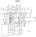
- FIG. 5 is an enlarged view illustrating a gap of a sealing mechanism according to a first modified example of the first embodiment.
- Components that are the same as the above-described components will be denoted by the same reference signs, and a description therefor will be omitted.
- the radial inner side surface 25f of the seal fixing spacer 25 is disposed so as to be located on the vertically higher side than the annular sealing member 5. Therefore, an upper side of FIG. 5 is a vertically lower side, and a lower side of FIG. 5 is a vertically higher side.
- the sealing mechanism 1A according to the first modified example of the first embodiment includes a lubricant groove 251 that stores a lubricant Lu to be supplied between the annular sealing member 5 and the radial outer surface 32p of the rotary portion 32.
- the seal fixing spacer 25 includes the radial inner side surface 25f.
- the radial inner side surface 25f faces the radial outer surface 32p of the rotary portion 32 and is located closer than the annular sealing member 5 to the high pressure side.
- the radial inner side surface 25f is located on the vertically higher side than the position of the annular sealing member 5.
- the lubricant groove 251 is an annular recessed portion provided at the radial inner side surface 25f of the seal fixing spacer 25.
- the lubricant Lu stored in the lubricant groove 25l is, for example, grease.
- the lubricant Lu partly spreads out of the lubricant groove 251 and contacts the radial outer surface 32p due to surface tension.
- the lubricant Lu is held by the lubricant groove 25l and the radial outer surface 32p. Further, since the lubricant Lu has flowability, the lubricant is stably supplied between the annular sealing member 5 and the radial outer surface 32p of the rotary portion 32 from the lubricant groove 251 by gravity. By this, even in the case where the lid portion 23 is disposed on the vertically lower side than the annular sealing member 5, the lubricant Lu is stably supplied between the annular sealing member 5 and the radial outer surface 32p of the rotary portion 32 from the lubricant groove 251 by gravity. Therefore, in the sealing mechanism 1A according to the first modified example of the first embodiment, frequency of replacing a component that improves sealing performance can be reduced even in the case where the lid portion 23 is disposed on the vertically lower side than the annular sealing member 5.
- the radial inner side surface 25f of the seal fixing spacer 25 is located closer than the position of the annular sealing member 5 to the high pressure side. Furthermore, the radial inner side surface 23f of the lid portion 23 is located closer than the position of the annular sealing member 5 to the low pressure side.
- the vacuum level can be adjusted by appropriately setting the distance ⁇ d1 of the gap s1 between the radial inner side surface 23f and the radial outer surface 32p.
- the distance ⁇ d1 is 0.001 mm or more and 0.5 mm or less, for example. Further, the distance ⁇ d1 is smaller than the size of the gap 55.
- the annular projecting portion 25e can adjust the vacuum level by appropriately setting the distance ⁇ d2 of the gap s2 between the radial inner side surface 25f and the radial outer surface 32p.
- the distance ⁇ d2 is 0.001 mm or more and 0.5 mm or less, for example. In the case of making the distance ⁇ d2 short, the lubricant Lu can be easily held at the gap 55.
- FIG. 6 is a cross-sectional view schematically illustrating a sealing mechanism according to a second modified example of the first embodiment.
- a sealing mechanism 1B according to the second modified example of the first embodiment can function as a separator between the two spaces having different pressures in the same manner as the first embodiment and the first modified example of the first embodiment, but is different in that the shaft 31 can be linearly moved in an axial direction of the shaft 31 in addition to rotary movement.
- Components that are the same as the above-described components will be denoted by the same reference signs, and a description therefor will be omitted.
- the sealing mechanism 1B according to the second modified example of the first embodiment includes the housing 2 and the rotary member 3. Unlike the above-described first embodiment, the housing 2 does not house a bearing 4, and the shaft 31 passes therethrough. Thus, unlike the above-described first embodiment, an axial position of the shaft 31 is not restricted by the bearing 4 or the like in the sealing mechanism 1B according to the second modified example of the first embodiment.
- the housing 2 includes, as the housing body, a seal fixing spacer 25A and a lid portion 23A. The seal fixing spacer 25A and the lid portion 23A are stacked in the axial direction.
- the lid portion 23A according to the second modified example of the first embodiment is fixed to the seal fixing spacer 25A with a fixing member 27A such as a bolt.
- the lid portion 23A according to the second modified example of the first embodiment includes a portion overlapping with the frame body 10 in a planar view and fixed to the frame body 10 with a fixing member 27B such as a bolt, in the same manner as the housing flange portion 22 according to the first embodiment.
- the lid portion 23A according to the second modified example of the first embodiment includes an annular groove at the portion overlapping with the frame body 10 in a planar view, and an O-ring (annular seal) 11 is fitted into the annular groove and improves sealing performance between the lid portion 23A and the frame body 10.
- the lid portion 23A includes the lubricant groove 231 at the annular sealing member 5 close to the internal space V, and stores a lubricant in the lubricant groove 231 for the annular sealing member 5.
- the annular sealing member 5 is constantly supplied with the lubricant from the lubricant groove 231.
- a length L1 from a surface of the lid portion 23A on the internal space V side to the lubricant groove 231 is, preferably, equal to or more than a stroke corresponding to a maximum length allowed by linear movement of the shaft 31.
- an end portion on the internal space V side of the lid portion 23A includes a cylindrical portion having a cylindrical shape, and an outer peripheral side of the cylindrical portion is formed uneven.
- the structure to secure the length L1 is not limited to the above unevenness, and the sealing mechanism 1B according to the according to the second modified example of the first embodiment can be downsized by using the lid portion 23A.
- the drive unit 6 of the sealing mechanism according to the second modified example of the first embodiment includes a rotary drive unit 8A and a linear drive unit 8B.
- the rotary drive unit 8A and the linear drive unit 8B are connected by a linear guiding mechanism 89.
- the rotary member 3 includes the shaft 31 and the conveyance table (movable member) 33.
- the shaft 31 is an output shaft (main shaft) of the sealing mechanism 1B, and has one end portion inserted into the housing 2.
- the shaft 31 has the other portion connected to the output shaft 81 of a motor unit 83 of the rotary drive unit 8A via the coupling 82.
- the conveyance table (movable member) 33 is fixed to the one end portion of the shaft 31.
- the rotary drive unit 8A includes the motor unit 83 and a detector 84 to detect rotation of the output shaft 81 inside a motor housing 80.
- the motor unit 83 includes a motor stator 83a and a motor rotor 83b inside the motor housing 80.
- the motor unit 83 is supported by a bearing 4A formed by combining bearings 44, 45, 46 such that the motor rotor 83b can be freely rotated around the rotational center axis Zr relative to the motor housing 80.
- the motor housing 80 is formed in a hollow cylindrical shape around the rotational center axis Zr, and the motor stator 83a and outer rings of the bearing 44, 45, 46 are fixed to an inner peripheral side of the motor housing 80. Further, inner rings of the bearings 44, 45, 46 are fixed to an outer periphery of the output shaft 81.
- the bearing 4A can also support the shaft 31 in a rotatable manner because the other end portion of the shaft 31 is connected to the output shaft 81 of the motor unit 83 of the rotary drive unit 8A via the coupling 82.
- the motor stator 83a has a cylindrical body having a cylindrical shape manufactured by stacking thin plates such as an electromagnetic steel plate and a cold-rolled steel sheet by means of bonding, boss, caulking, and the like.
- the exciting coil is a liner wire and able to generate a rotation magnetic field by receiving power supply under control of a control device 91 and exciting the motor stator 83a.
- the motor stator 83a is a so-called stator of the motor unit 83.
- magnets are fixed on an outer peripheral side of a core material around the rotational center axis Zr.
- the plurality of magnets are provided in a circumferential direction and attached along an outer peripheral surface on a radially outer side of the motor rotor 83b.
- the magnets are permanent magnets, and S poles and N poles are alternately arranged at equal intervals in the circumferential direction of the motor rotor 83b.
- This type of motor rotor 83b can be called as a permanent magnet (PM) type rotor.
- the motor rotor 83b is rotated in accordance with the rotation magnetic field excited at teeth of the motor stator core by the exciting coil.
- the detector 84 is, for example, a resolver device and positioned at an end portion in the axial direction (direction parallel to rotation center) of the motor unit 83.
- the detector 84 includes a resolver stator 84a and a resolver rotor 84b.
- the resolver rotor 84b is connected to one end of the motor rotor 83b.
- the resolver stator 84a is fixed at the motor housing 80.
- the detector 84 can output a detection signal from the resolver stator 84a in accordance with rotation of the resolver rotor 84b linked with rotation of the motor rotor 83b.
- the control device 91 receives the detection signal from the resolver stator 84a and can detect rotation of the output shaft 81.
- the detector 84 is not limited to the resolver device and may also be, for example, another magnetic sensor or rotation detection sensor.
- the linear drive unit 8B includes a drive motor 90, a screw shaft 85, a connecting unit 86, a support member 87, a positioning portion 88, and the linear guiding mechanism 89.
- the drive motor 90 is an electric motor same as the electric motor 8.
- the structure of the linear drive unit 8B is not limited thereto.
- the linear drive unit 8B may be any linear drive unit that provides freedom of movement in linear movement parallel to the axial direction of the shaft 31.
- the drive motor 90 has a base position fixed by the support member 87 relative to the frame body 10.
- the screw shaft 85 and the connecting unit 86 form a ball screw mechanism, and the drive motor 90 converts transmitted rotation of the screw shaft 85 to linear movement and then moves the connecting unit 86 in a MZ direction parallel to an extending direction of the screw shaft 85 (axial direction of the screw shaft 85).
- the connecting unit 86 is connected to the positioning portion 88, and the position of the positioning portion 88 moves together with a position determined based on guide of the linear guiding mechanism 89 in accordance with linear movement of the connecting unit 86.
- the positioning portion 88 is a table, and the rotary drive unit 8A is mounted on an upper surface thereof. Therefore, the linear drive unit 8B can linearly move the shaft 31 together with the rotary drive unit 8A along the axial direction of the shaft 31 (linear movement).
- the control device 91 according to the second modified example of the first embodiment controls the motor unit 83 of the rotary drive unit 8A and the drive motor 90 of the linear drive unit 8B to provide the shaft 31 with at least one of rotary movement and linear movement. Therefore, the control device 91 according to the second modified example of the first embodiment can control the motor unit 83 of the rotary drive unit 8A and the drive motor 90 of the linear drive unit 8B so as to provide the conveyance table (movable member) 33 with at least one of rotary movement and linear movement. Further, the conveyance device 7 includes the conveyance table (movable member) 33 to move a conveyance object. The conveyance device 7 moves the conveyance object by linking movement of the conveyance table (movable member) 33 with at least one of rotary movement and linear movement of the shaft 31.
- the shaft 31 performs at least one of rotary movement and linear movement in a state that the annular sealing member 5 is fixed to the housing 2. Therefore, friction is caused between the annular sealing member 5 and the shaft 31.
- the sealing mechanism 1B according to the second modified example of the first embodiment includes the annular sealing member 5 and the lubricant groove 231 to store the lubricant, a state that the lubricant is present between a radial outer surface 31p of the shaft 31 and the annular sealing member 5 can be easily secured. Therefore, abrasion of the annular sealing member 5 or the shaft 31 is suppressed, and frequency of replacing a component that improves sealing performance can be reduced in the sealing mechanism 1B according to the second modified example of the first embodiment.
- FIG. 7 is a cross-sectional view schematically illustrating a sealing mechanism according to a third modified example of the first embodiment.
- Components that are the same as the above-described components will be denoted by the same reference signs, and a description therefor will be omitted.
- a sealing mechanism 1C according to the third modified example of the first embodiment includes, as a housing body, the seal fixing spacer 25A and a lid portion 23B.
- the seal fixing spacer 25A and the lid portion 23B are stacked in an axial direction.
- the radial inner side surface 25f of the seal fixing spacer 25A is located on the vertically higher side than the annular sealing member 5. Therefore, an upper side of FIG. 7 is a vertically lower side, and a lower side of FIG. 7 is a vertically higher side.
- the sealing mechanism 1C according to the third modified example of the first embodiment includes the lubricant groove 251.
- the lubricant groove 251 is the annular recessed portion provided at the radial inner side surface 25f of the seal fixing spacer 25A.
- the lubricant is stored in the lubricant groove 25l.
- the lubricant partly spreads out of the lubricant groove 251 and contacts the radial outer surface 31p of the shaft 31 due to surface tension.
- the lubricant is held by the lubricant groove 251 and the radial outer surface 31p.
- the lubricant since the lubricant has flowability, the lubricant is stably supplied between the annular sealing member 5 and the radial outer surface 31p of the shaft 31 from the lubricant groove 251 by gravity.
- the lubricant is stably supplied between the annular sealing member 5 and the radial outer surface 31p of the shaft 31 from the lubricant groove 251 by gravity. Therefore, in the sealing mechanism 1C according to the third modified example of the first embodiment, frequency of replacing a component that improves sealing performance can be reduced even in the case where the lid portion 23B is disposed on the vertically lower side than the annular sealing member 5.
- FIG. 8 is a cross-sectional view schematically illustrating a manufacturing device including a sealing mechanism according to a second embodiment.
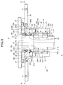
- FIG. 9 is a cross-sectional view schematically illustrating the sealing mechanism according to the second embodiment.
- FIGS. 8 and 9 are the cross-section surfaces illustrating a sealing mechanism 1D taken along a plane including a rotational center axis Zr of the sealing mechanism 1D and parallel to the rotational center axis Zr.
- FIG. 10 is a view taken on arrow B - B of FIG. 9 .
- FIG. 11 is an enlarged view illustrating a gap of the sealing mechanism according to the second embodiment.
- Components that are the same as above-described components will be denoted by the same reference signs, and a description therefor will be omitted.
- the sealing mechanism 1D includes two annular sealing members 5A, 5B to seal a gap 55 at different positions in a direction along the rotational center axis Zr.
- the two annular sealing members 5A, 5B are disposed at the different positions, but these annular sealing members are the same components.
- the two annular sealing members 5A, 5B are same as an annular sealing member 5 of a first embodiment.
- the number of annular sealing members may be any number greater than 1 and may also be three or more.
- a housing 2 according to the second embodiment includes a lid portion 23, an outer ring stopper member 24, a seal fixing spacer 25, and a seal fixing spacer 28.
- the lid portion 23 is fixed to a housing flange portion 22 with a bolt 27.
- the outer ring stopper member 24, the seal fixing spacer 25, and the seal fixing spacer 28 are disposed inside a barrel portion 21 of a housing body.
- the sealing mechanism 1D is disposed such that the through-hole is located along a vertical direction and an internal space V side of the through-hole is located on a vertically higher side. Therefore, an upper side of FIGS. 8 and 9 is a vertically higher side, and a lower side in FIGS. 8 and 9 is a vertically lower side.
- the seal fixing spacer 25 determines a size of the gap 55 and further fixes the annular sealing member 5A. As illustrated in FIG. 10 , the seal fixing spacer 25 is an annular member. Since the seal fixing spacer 25 functions as a guide of the annular sealing member 5A, an appropriate setting value can be set for a contact pressure of the annular sealing member 5A that contacts the rotary portion 32.
- the seal fixing spacer 28 is an annular member, and determines the size of the gap 55 and further fixes the annular sealing member 5B. As illustrated in FIG. 9 , the seal fixing spacer 28 includes a seal fixing recessed portion 28b, a radial inner peripheral portion 28c, and a radial outer peripheral portion 28d. At least a part of the radial outer peripheral portion 28d contacts an inner wall 21b of the through-hole of the barrel portion 21. Since the seal fixing spacer 28 functions as a guide of the annular sealing member 5B, an appropriate setting value can be set for a contact pressure of the annular sealing member 5B that contacts the rotary portion 32.
- annular groove 22a is formed concentrically with the rotational center axis Zr, and at least a part of the radial outer peripheral portion 25d constitutes a part of a wall surface of the annular groove 22a.
- an O-ring (second annular sealing member) 26 fitted into the annular groove 22a functions as a seal with improved sealing performance. Then, the O-ring (second annular sealing member) 26 is disposed at a position where a diameter thereof is larger than those of the annular sealing members 5A, 5B.
- the spacer positioning portion 25a is sandwiched and fixed between the radial outer peripheral portion 28d of the above-described seal fixing spacer 28 and the inner wall 21b of the through-hole at the barrel portion 21.
- the annular groove 22a and the O-ring (second annular sealing member) 26 are not needed in the case where a vacuum level of the internal space V is low.
- the annular sealing member 5A is disposed so as to draw a concentric circle around the rotational center axis Zr in the same manner as a rotary portion 32, the seal fixing spacer 25, the O-ring (second annular sealing member) 26 fixed to the housing flange portion 22, and an O-ring 11.
- the annular sealing member 5B is also disposed so as to draw a concentric circle around the rotational center axis Zr in the same manner as the annular sealing member 5A.
- the annular sealing members 5A, 5B are disposed closer than the bearing 4 to the internal space V that is a low-pressure side space of the two spaces having different pressures. With this structure, the annular sealing members 5A, 5B prevent a lubricant and the like used in the bearing 4 from spattering on the internal space V side.
- the seal fixing spacer 25 sandwiches and fixes a seal flange portion 54 inserted into a seal fixing recessed portion 25b.
- the annular sealing member 5A includes the seal flange portion 54. Therefore, the sealing mechanism 1D can reduce possibility that the annular sealing member 5A is rotated together with rotation of the rotary portion 32.
- the seal fixing spacer 28 sandwiches and fixes the seal flange portion 54 inserted into the seal fixing recessed portion 28b.
- the annular sealing member 5B includes the seal flange portion 54. Therefore, the sealing mechanism 1D can reduce possibility that the annular sealing member 5B is rotated together with rotation of the rotary portion 32.
- the sealing mechanism 1D includes a lubricant groove 25l that stores a lubricant Lu to be supplied between the annular sealing members 5A, 5B and a radial outer surface 32p of the rotary portion 32.
- the seal fixing spacer 25 includes a radial inner side surface 25f that faces the radial outer surface 32p of the rotary portion 32 at a position between the annular sealing members 5A, 5B.
- the radial inner side surface 25f is located on the vertically higher side than a position of the annular sealing member 5B.
- the lubricant groove 25l is a recessed portion provided at the radial inner side surface 25f of the seal fixing spacer 25.
- the lubricant groove 25l is formed in an annular shape as indicated by a dotted line in FIG. 10 .
- the lubricant Lu stored in the lubricant groove 25l is, for example, grease.
- the lubricant Lu partly spreads out of the lubricant groove 25l and contacts the radial outer surface 32p due to surface tension. By this, the lubricant Lu is held by the lubricant groove 25l and the radial outer surface 32p. Further, since the lubricant Lu has flowability, the lubricant is stably supplied between the annular sealing member 5B and the radial outer surface 32p of the rotary portion 32 from the lubricant groove 25l by gravity. This easily keeps a state that the lubricant Lu is present between the radial outer surface 32p of the rotary portion 32 and the annular sealing member 5B.
- the lubricant Lu is supplied to the annular sealing member 5A by a pressure caused by slight air leakage between the rotary portion 32 and the annular sealing member 5B. Furthermore, the lubricant Lu is also supplied to the annular sealing member 5A at the time of pressure change in the internal space V (start-up time and stop time of a manufacturing device 100). Therefore, abrasion of the annular sealing members 5A, 5B or the rotary portion 32 is suppressed. Therefore, the sealing mechanism 1D can reduce frequency of replacing a component that improves sealing performance.
- the annular sealing member 5A out of the annular sealing members 5A, 5B is located closer than the lubricant groove 25l to the low pressure side.
- the lubricant Lu that has been transferred to the annular sealing member 5A side from the lubricant groove 251 is prevented from being transferred to the internal space V by the annular sealing member 5A. Therefore, the sealing mechanism 1D can reduce possibility of spattering, to the internal space V, the lubricant Lu to be supplied to a surface of a contact type seal.
- surfaces of the annular sealing members 5A, 5B and the rotary portion 32 have a certain level of surface roughness including fine unevenness. Therefore, sealing performance at a portion where the annular sealing members 5A, 5B contact the rotary portion 32 may depend on the level of surface roughness.
- the lubricant Lu is supplied to the surfaces of annular sealing members 5A, 5B and the rotary portion 32, the lubricant Lu is filled into recessed portions included in the surface roughness. Therefore, in the sealing mechanism 1D, the surface roughness of the annular sealing members 5A, 5B and the rotary portion 32 is improved by the lubricant Lu, and sealing performance can be improved.
- the lid portion 23 can adjust a vacuum level by appropriately setting a distance ⁇ d1 of a gap s1 between a radial inner side surface 23f and the radial outer surface 32p.
- the distance ⁇ d1 is 0.001 mm or more and 0.5 mm or less, for example.
- the lubricant groove 251 is provided at a part of the radial inner side surface 25f as illustrated in FIG. 11 .
- the seal fixing spacer 25 can adjust a vacuum level by suitably setting a distance ⁇ d2 of a gap s2 between the radial outer surface 32p and a portion in the radial inner side surface 25f, the portion being located closer than the lubricant groove 25l to the annular sealing member 5A side. Further, the seal fixing spacer 25 can adjust a vacuum level by suitably setting the distance ⁇ d2 of a gap s3 between the radial outer surface 32p and a portion in the radial inner side surface 25f, the portion being located closer than the lubricant groove 25l to the annular sealing member 5B side.
- the distance ⁇ d2 is 0.001 mm or more and 0.5 mm or less, for example. Further, the distance ⁇ d2 is smaller than the size of the gap 55.
- the gaps s2, s3 in the second embodiment are the gaps having the same distance ⁇ d2, but may also be the gaps having different distances.
- a lip portion 51 has a pressure caused by elastic deformation of the lip portion 51 and receives a pressure applied to a biasing member 56, thus the lip portion 51 contacts the radial outer surface 32p of the rotary portion 32. Therefore, the sealing mechanism 1D can increase a contact pressure of the lip portion 51 to the radial outer surface 32p of the rotary portion 32. Further, the space surrounded by a fixing portion 52, an annular connecting unit 53, and the lip portion 51 is opened to an external space E that is a high-pressure side space of the two spaces having the different pressures.
- a pressure difference between the two spaces having different pressures can increase the contact pressure of the lip portion 51 that contacts the radial outer surface 32p of the rotary portion 32.
- This enables the sealing mechanism 1D to keep high sealing performance even when the internal space V is highly vacuumed.
- an inner peripheral side end 51a of the lip portion 51 contacts the radial outer surface 32p but also at least a part of an inner peripheral side base portion 51d of the lip portion 51 close to the annular connecting unit 53 contacts the radial outer surface 32p.
- the sealing performance can be secured because the inner peripheral side of the lip portion 51 comes into surface contact with the radial outer surface 32p.
- the sealing mechanism 1D can reduce frequency of replacing the annular sealing members 5A, 5B or the rotary portion 32 serving as components that improve sealing performance.
- the space surrounded by the lip portion 51, annular connecting unit 53, and fixing portion 52 is opened to the external space E on the high pressure side of the two spaces that are the internal space V and the external space E having the different pressures.
- the through-hole of the barrel portion 21 is arranged along the vertical direction in the sealing mechanism 1D, but the through-hole may also be arranged along a horizontal direction.
- the lubricant groove 251 is located on the vertically higher side than the rotary portion 32. Therefore, the lubricant Lu is supplied to the radial outer surface 32p of the rotary portion 32 by gravity. Then, the lubricant Lu passes along the radial outer surface 32p, and is supplied between the annular sealing members 5A, 5B and the rotary portion 32.
- the sealing mechanism 1D can function as a separator between the two spaces that are the internal space V and the external space E having the different pressures.
- the sealing mechanism 1D includes the housing 2, the shaft 31 inserted into the housing 2, the bearing 4 provided at the housing 2 and supporting the shaft 31 in a rotatable manner, and the rotary portion 32.
- the rotary portion 32 is provided at one end portion of the shaft 31, rotated together with the shaft 31, and further having the radial outer surface 32p facing the seal fixing spacer 25 of the housing 2 with the gap 55 having the predetermined size.
- the sealing mechanism 1D includes the plurality of annular sealing members 5A, 5B to seal the gap 55 at the different positions, and the lubricant groove 25l that stores the lubricant Lu to be supplied between the annular sealing members 5A, 5B and the radial outer surface 32p of the rotary portion 32.
- the annular sealing member 5A that is one of the annular sealing members 5A, 5B is located closer than the lubricant groove 25l to the low pressure side of the two spaces having the different pressures.
- the housing 2 includes the seal fixing spacer 25 that determines the size of the gap 55 and further fixes the annular sealing member 5A.
- the radial inner side surface 25f of the seal fixing spacer 25 is located between the annular sealing members 5A, 5B, and the lubricant groove 25l is provided at the radial inner side surface 25f of the seal fixing spacer 25.
- the lubricant Lu is easily supplied to the surfaces of the plurality of annular sealing members 5A, 5B. Therefore, abrasion of the annular sealing members 5A, 5B or the rotary portion 32 is suppressed. Therefore, the sealing mechanism 1D can reduce frequency of replacing a component that improves sealing performance.
- the lubricant groove 25l is provided at a part of the radial inner side surface 25f of the seal fixing spacer 25. Furthermore, the distances ⁇ d2 between the radial outer surface 32p of the rotary portion 32 and portions in the radial inner side surface 25f of the seal fixing spacer 25 are smaller than the size of the gap 55, the portions being located closer than the lubricant groove 251 to the annular sealing members 5A, 5B sides, respectively. This makes the lubricant Lu gradually pass through the gaps s2, s3 between the radial inner side surface 25f and the radial outer surface 32p. Therefore, the sealing mechanism 1D can suppress the situation that a large amount of the lubricant Lu is supplied to the annular sealing members 5A, 5B sides.
- FIG. 12 is an enlarged view illustrating a gap of a sealing mechanism according to a first modified example of the second embodiment.
- a sealing mechanism 1E according to the first modified example of the second embodiment includes a lubricant groove 321 that stores the lubricant Lu to be supplied between the annular sealing members 5A, 5B and the radial outer surface 32p of the rotary portion 32.
- the lubricant groove 32l is provided at a portion in the radial outer surface 32p of the rotary portion 32, the portion facing the radial inner side surface 25f of the seal fixing spacer 25. More specifically, as illustrated in FIG. 12 , the lubricant groove 32l is provided in a portion of the radial outer surface 32p of the rotary portion 32 sandwiched between a flat surface S1 and a flat surface S2.
- the flat surface S1 is vertical to the rotational center axis Zr and passes an end portion on the annular sealing member 5A side of the radial inner side surface 25f
- the flat surface S2 is vertical to the rotational center axis Zr and passes at an end portion on the annular sealing member 5B side of the radial inner side surface 25f.
- the lubricant groove 321 is provided in an annular shape around the rotational center axis Zr. For example, the lubricant Lu partly spreads out of the lubricant groove 32l and contacts the radial inner side surface 25f of the seal fixing spacer 25 due to surface tension. By this, the lubricant Lu is held by the lubricant groove 32l and the radial inner side surface 25f.
- the lubricant Lu since the lubricant Lu has flowability, the lubricant is stably supplied between the annular sealing member 5B and the radial outer surface 32p of the rotary portion 32 from the lubricant groove 32l by gravity. This easily keeps a state that the lubricant Lu is present between the radial outer surface 32p of the rotary portion 32 and the annular sealing member 5B. Further, the lubricant Lu is supplied to the annular sealing member 5A by a pressure caused by slight air leakage between the rotary portion 32 and the annular sealing member 5B. Furthermore, the lubricant Lu is also supplied to the annular sealing member 5A at the time of pressure change in the internal space V (start-up time and stop time of a manufacturing device 100). Therefore, abrasion of the annular sealing members 5A, 5B or the rotary portion 32 is suppressed. Therefore, the sealing mechanism 1E can reduce frequency of replacing a component that improves sealing performance.
- the lubricant groove 321 is at least located in the portion sandwiched between the flat surface S1 and the flat surface S2 out of the radial outer surface 32p of the rotary portion 32, and is not necessarily provided in the annular shape around the rotational center axis Zr.
- the lubricant groove 321 may also be provided in an annular shape around a straight line that forms an angel relative to the rotational center axis Zr, for example.
- the lubricant groove 32l is provided at a part of the portion in the radial outer surface 32p of the rotary portion 32, the portion facing the radial inner side surface 25f of the seal fixing spacer 25.
- the seal fixing spacer 25 can adjust a vacuum level by suitably setting the distance ⁇ d2 of the gap s2 between the radial inner side surface 25f of the seal fixing spacer 25 and a portion in the radial outer surface 32p of the rotary portion 32, the portion being located closer than the lubricant groove 321 to the annular sealing member 5A side.
- the seal fixing spacer 25 can adjust a vacuum level by suitably setting the distance ⁇ d2 of the gap s3 between the radial inner side surface 25f of the seal fixing spacer 25 and a portion in the radial outer surface 32p of the rotary portion 32, the portion being located closer than the lubricant groove 321 to the annular sealing member 5B side.
- the distance ⁇ d2 is 0.001 mm or more and 0.5 mm or less, for example.
- the distance ⁇ d2 is smaller than the size of the gap 55. This makes the lubricant Lu gradually pass through the gaps s2, s3 between the radial inner side surface 25f and the radial outer surface 32p.
- the gaps s2, s3 in the first modified example of the second embodiment are the gaps having the same distance ⁇ d2, but may also be the gaps having different distances.
- FIG. 13 is a cross-sectional view schematically illustrating a sealing mechanism according to a second modified example of the second embodiment.
- a sealing mechanism 1F according to the second modified example of the second embodiment can function as a separator between the two spaces having different pressures in the same manner as the second embodiment and the first modified example of the second embodiment, but is different in that the shaft 31 can be linearly moved in the axial direction of the shaft 31 in addition to rotary movement.
- Components that are the same as the above-described components will be denoted by the same reference signs, and a description therefor will be omitted.
- the housing 2 includes, as a housing body, a seal fixing spacer 28A, the seal fixing spacer 25A, and the lid portion 23B.
- the seal fixing spacer 28A, the seal fixing spacer 25A, and the lid portion 23B are stacked in the axial direction.
- seal fixing spacer 28A In the seal fixing spacer 28A according to the second modified example of the second embodiment, a portion overlapping with the seal fixing spacer 25A in a planar view is fixed with a fixing member 27C such as a bolt.
- the seal fixing spacer 28A includes an annular groove at the portion overlapping with the seal fixing spacer 25A in a planar view, and an O-ring (second annular sealing member) 26B is fitted into the annular groove to improve sealing performance between the seal fixing spacer 25A and the seal fixing spacer 28A.
- the seal fixing spacer 28A is fixed to the seal fixing spacer 25A with the fixing member 27C such as a bolt, and thus the O-ring (second annular sealing member) 26B fitted into the annular groove functions as a seal with improved sealing performance.
- seal fixing spacer 28A abuts on the other axial end of the seal fixing spacer 25A.
- O-ring (second annular sealing member) 26B is disposed at a position where a diameter thereof is larger than that of the annular sealing member 5B.
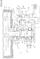
- FIG. 14 is a cross-sectional view schematically illustrating a sealing mechanism according to a third modified example of the second embodiment.
- Components that are the same as the above-described components will be denoted by the same reference signs, and a description therefor will be omitted.
- a pressure in a space between the annular sealing member 5A and the annular sealing member 5B (hereinafter referred to as pressure between seals) is an intermediate pressure between the internal space V and the external space E of a frame body 10.
- pressure between seals is an intermediate pressure between the internal space V and the external space E of a frame body 10.
- the pressure between the seals becomes close to the pressure in the internal space V of the frame body 10, for example, low vacuum.
- a sealing mechanism 1G according to the third modified example of the second embodiment includes a flow passage 25H in the housing 2, and the flow passage functions as an exhaust line connected to a space between the annular sealing member 5A and the annular sealing member 5B.
- the pressure between the seals becomes constant by exhausting a gas in the space between the annular sealing member 5A and the annular sealing member 5B via the flow passage 25H. As a result, the sealing mechanism 1G can shorten the warm-up time.
- the sealing mechanism 1G further includes: a pump 92 as a pressure changing device; and a measuring instrument 93 to measure a pressure or a gas flow rate inside the flow passage 25H.
- a control device 91 may perform pressure control by controlling an exhaust amount of the gas of the pump 92 based on the measured pressure or gas flow rate inside the flow passage 25H so as to make the pressure between the seals constant.
- the sealing mechanism 1G records temporal change of the pressure or the gas flow rate inside the flow passage 25H measured by the control device 91. In the case where a measured value exceeds a threshold value, the sealing mechanism 1G can issue a warning to notify deterioration of the annular sealing members 5A or the annular sealing member 5B. As a result, replacement timing of the annular sealing members 5A or the annular sealing member 5B can be determined before serious influence is given to the internal space V of the frame body 10.
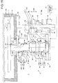
- FIG. 15 is a cross-sectional view illustrating a sealing mechanism according to a fourth modified example of the second embodiment.
- Components that are the same as the above-described components will be denoted by the same reference signs, and a description therefor will be omitted.
- lubricant grooves 25l are disposed at both sides of the flow passage 25H respectively. More specifically, the flow passage 25H is disposed between the two lubricant grooves 25l.
- the flow passage 25H functions as an exhaust line or a supply line.
- the sealing mechanism 1H includes an exhaust pump 92a and a supply pump 92b as pressure change devices.
- the exhaust pump 92a When the exhaust pump 92a is operated out of the exhaust pump 92a and the supply pump 92b, a gas in the space between the annular sealing member 5A and the annular sealing member 5B is exhausted via the flow passage 25H, thereby making the pressure between the seals constant. As a result, the sealing mechanism 1H can shorten the warm-up time.
- the supply pump 92b When the supply pump 92b is operated out of the exhaust pump 92a and the supply pump 92b, the pressure in the space between the annular sealing member 5A and the annular sealing member 5B is increased, thereby supplying the lubricant in the lubricant groove 25l to the annular sealing member 5A and the annular sealing member 5B.
- the lubricant can be supplied to the annular sealing member 5A and the annular sealing member 5B in a purposeful manner. For example, even in the case where a stroke of the shaft 31 is short, the lubricant is easily supplied to the annular sealing member 5A and the annular sealing member 5B in the sealing mechanism 1H.
- the sealing mechanism 1H includes a lubricant supply unit 94 and a lubricant supply unit 95.
- the lubricant supply unit 94 and the lubricant supply unit 95 can supply the lubricant to the lubricant groove 25l via a flow passage or the like provided at the housing 2, for example. This enables the sealing mechanism 1H to easily supply the lubricant to the lubricant groove 251 even in the case where the lubricant stored in the lubricant groove 25l is decreased.
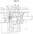
- FIG. 16 is an enlarged view illustrating a gap of a sealing mechanism according to a third embodiment.
- Components that are the same as the above-described components will be denoted by the same reference signs, and a description therefor will be omitted.
- a sealing mechanism 1I according to the third embodiment is an example in which an annular sealing member 5 is provided but a lubricant groove is not provided at a housing 2.
- FIG. 17 is an enlarged view illustrating a gap of a sealing mechanism according to a first modified example of the third embodiment.
- a biasing member 56 is, for example, made of stainless steel or the like and in all cases, the biasing member is an elastic body formed in a U-shape in a cross-sectional view obtained by bending, at a bending portion 56c, a plate-like portion 56a and a plate-like portion 56b which are flat plates.
- the bending portion 56c is bent so as to have a predetermined curvature. Further, the biasing member 56 performs biasing such that ends of the plate-like portion 56a and plate-like portion 56b are mutually outstretched.
- FIG. 18 is an enlarged view illustrating a gap of a sealing mechanism according to a second modified example of the third embodiment.
- the biasing member 56 is a linear member of stainless steel and, for example, is wound around as a coil spring in a cylindrical spiral form.
- the biasing member 56 is disposed inside a space surrounded by a fixing portion 52, an annular connecting unit 53, and a lip portion 51 and located on a radial outer side of a lip portion 51. Further, a diameter determined by a rotary portion 32 and the lip portion 51 is set larger than a diameter of the coil spring of the biasing member 56. By this, the biasing member 56 can bias pressing force of the lip portion 51 toward the rotary portion 32 side.
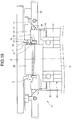
- FIG. 19 is a cross-sectional view illustrating a sealing mechanism according to a third modified example of the third embodiment.
- the annular sealing member 5 does not include a seal flange portion 54. Therefore, a seal fixing recessed portion 25b is not also provided in a seal fixing spacer 25.
- the annular sealing member 5 is fixed by repellent force generated between the seal fixing spacer 25 and the rotary portion 32. Co-rotation is more suppressed in the sealing mechanism 1I according to the third embodiment than the sealing mechanism 1L according to the third modified example of the third embodiment. Therefore, sealing performance can be secured even when a rotation speed of a rotary member 3 is accelerated. Therefore, the sealing mechanism 1I according to the third embodiment can keep an internal space V having a higher vacuum level than the sealing mechanism 1L according to the third modified example of the third embodiment. On the other hand, depending on the rotation speed of the rotary member 3, the sealing mechanism 1L according to the third modified example of the third embodiment can also be used. In the sealing mechanism 1L according to the third modified example of the third embodiment, since the annular sealing member 5 and the seal fixing spacer 25 each have a simple shape, a processing load is reduced and cost can be reduced.
- FIG. 20 is a cross-sectional view illustrating a sealing mechanism according to a fourth modified example of the third embodiment.
- a sealing mechanism 1M according to the fourth modified example of the third embodiment can function as a separator between two spaces having different pressures in the same manner as the third embodiment and the first to third modified examples of the third embodiment, but is different in that a shaft 31 can be linearly moved in the axial direction of the shaft 31 in addition to rotary movement.
- Components that are the same as the above-described components will be denoted by the same reference signs, and a description therefor will be omitted.
- FIG. 21 is a cross-sectional view illustrating a sealing mechanism according to a fifth modified example of the third embodiment.
- a sealing mechanism 1N according to the fifth modified example of the third embodiment differs from the fourth modified example of the third embodiment in including a guide member 29.
- Components that are the same as the above-described components will be denoted by the same reference signs, and a description therefor will be omitted.
- the guide member 29 is a cylindrical member and fixed to a seal fixing spacer 25A with a fixing member 27D such as a bolt.
- the guide member 29 includes, on an inner wall thereof, a bearing 291 that is, for example, a linearly-moving ball bearing.
- the bearing 291 is provided with a lubricant. Since the bearing 291 contacts the shaft 31, the guide member 29 can guide the shaft 31.
- a length L2 from a surface on the internal space V side of the bearing 291 to the annular sealing member 5 is equal to or larger than a stroke that is a maximum length allowed by linear movement of the shaft 31. This suppresses mixture of a lubricant of the annular sealing member 5 with the lubricant of the bearing 291.
- the sealing mechanism 1N can suppress deterioration of the lubricants.
- the annular sealing member 5 of the sealing mechanism 1N is not provided with the seal flange portion 54 in the same manner as the sealing mechanism 1L according to third modified example of the third embodiment.
- the seal flange portion 54 is not provided in view of the points that reduction of the processing load and cost reduction can be achieved.
- the annular sealing member 5 of the sealing mechanism 1N may include the seal flange portion 54.
- first to third embodiments have been described above, the first to third embodiments are not limited by the matters described above. Further, at least one of various kinds of omission, replacement, and modifications can be made in respect to the components in a range without departing from the gist of the first to third embodiments.
Landscapes
- Sealing Devices (AREA)
- Sealing With Elastic Sealing Lips (AREA)
- Container, Conveyance, Adherence, Positioning, Of Wafer (AREA)
- Sealing Of Bearings (AREA)
Abstract
Description
- The present invention relates to a sealing mechanism functioning as a separator between two spaces having different pressures, a drive unit of the sealing mechanism, a conveyance device, and a manufacturing device.
- In a conveyance device and a manufacturing device such as a semiconductor manufacturing device or a machine tool, a sealing mechanism to rotate a rotary stage or rotate a semiconductor substrate, a workpiece, or a tool is used. As such a sealing mechanism, for example, a positioning device is disclosed in Patent Literature 1 (refer to
FIG. 2 ). - Patent Literature 1: Japanese Patent Application Laid-open Publication No.
2007-9939 - According to the technology disclosed in
Patent Literature 1, an O-ring that is a contact-type seal is housed inside a seal groove, thereby rotating a shaft while separating an external environment from the inside of a process chamber such as a vacuum chamber. Unfortunately, the O-ring or the shaft may be deformed or abraded because the O-ring is forcedly deformed to contact the shaft although the O-ring improves sealing performance. Since it takes time and labor to perform component replacement due to deformation or abrasion of the O-ring or the shaft, there is a demand to reduce frequency, and further, it is desired to provide a sealing mechanism in which the frequency of component replacement is reduced by suppressing time degradation of a component that improves sealing performance. - The present invention is achieved in view of the above-described situation, and has an objective to provide a sealing mechanism, a drive unit of the sealing mechanism, a conveyance device, and a manufacturing device, in which frequency of replacing a component that improves sealing performance is reduced.
- To achieve the above objective, a sealing mechanism according to a first aspect functions as a separator between two spaces having different pressures and includes: a housing; a shaft inserted into the housing; an annular sealing member sealing a gap by contacting a radial outer surface of the shaft or a radial outer surface of a rotary portion fixed to the shaft; and a lubricant groove storing a lubricant to be supplied between the annular sealing member and the radial outer surface. By this, a state that the lubricant is present between the radial outer surface and the annular sealing member can be easily secured. Therefore, abrasion of the annular sealing member, shaft, or rotary portion is suppressed. Therefore, the sealing mechanism according to the present invention can reduce frequency of replacing a component that improves sealing performance.
- As a desirable embodiment, preferably, the housing includes: a seal fixing spacer determining a size of the gap and further fixing the annular sealing member; and a lid portion fixing the seal fixing spacer, a radial inner side surface of the lid portion is located on a vertically higher side than a position of the annular sealing member, and the lubricant groove is provided at the radial inner side surface of the lid portion. By this, the lubricant is stably supplied between the annular sealing member and the radial outer surface from the lubricant groove by gravity.
- As a desirable embodiment, preferably, the radial inner side surface of the lid portion is located closer than a position of the annular sealing member to a low pressure side of the two spaces having different pressures, the lubricant groove is provided at a part of the radial inner side surface of the lid portion, and a distance between the radial outer surface and a portion in the radial inner side surface of the lid portion, the portion in the radial inner side surface being located closer than the lubricant groove to the low pressure side of the two spaces having different pressures is smaller than a size of the gap. This makes the lubricant hardly pass through an area between the lid portion and the radial outer surface. Therefore, a situation that the lubricant is spattered on the internal space side is suppressed.
- As a desirable embodiment, preferably, the housing includes: a seal fixing spacer determining a size of the gap and further fixing the annular sealing member; and a lid portion fixing the seal fixing spacer, a radial inner side surface of the seal fixing spacer is located on the vertically higher side than a position of the annular sealing member, and the lubricant groove is provided at the radial inner side surface of the seal fixing spacer. By this, even in the case where the lid portion is disposed on a vertically lower side than the annular sealing member, the lubricant Lu is stably supplied between the annular sealing member and the radial outer surface from the lubricant groove by gravity. Therefore, in the sealing mechanism, the frequency of replacing the component that improves sealing performance can be reduced even in the case where the lid portion is disposed on the vertically lower side than the annular sealing member.
- As a desirable embodiment, preferably, the radial inner side surface of the seal fixing spacer is located closer than the position of the annular sealing member to a high pressure side of the two spaces having different pressures, the radial inner side surface of the lid portion is located closer than the position of the annular sealing member to the low pressure side of the two spaces having different pressures, and a distance between the radial inner side surface of the lid portion and the radial outer surface is smaller than the size of the gap. This makes the lubricant hardly pass through the area between the lid portion and the radial outer surface. Therefore, the situation that the lubricant is spattered on the internal space side is suppressed.
- As a desirable embodiment, preferably, the shaft is supported in a rotatable manner. By this, the sealing mechanism can transmit rotary movement between the two spaces having different pressures or gases.
- As a desirable embodiment, preferably, the shaft is supported in a linearly movable manner such that a relative position to the housing is axially changed. By this, the sealing mechanism can transmit linear movement between the two spaces having different pressures or gases.
- A desirable embodiment is preferably a drive unit of a sealing mechanism including: the above-described sealing mechanism; and a drive unit applying at least one of rotary movement and linear movement to the shaft. With this structure, high sealing performance can be achieved in the drive unit of the sealing mechanism.
- A desirable embodiment is preferably a conveyance device including: the above-described sealing mechanism; and a movable member moving a conveyance object, and movement of the movable member is linked with at least one of rotary movement and linear movement of the shaft. With this structure, high sealing performance can be achieved in the conveyance device.
- A desirable embodiment is preferably a manufacturing device including the above-described sealing mechanism. With this structure, high sealing performance can be achieved in the manufacturing device, and product quality can be improved.
- A sealing mechanism according to a second aspect is, preferably, a sealing mechanism functioning as a separator between the two spaces having different pressures, and includes: a housing; a shaft inserted into the housing; a plurality of annular sealing members sealing a gap at different positions by contacting a radial outer surface of the shaft or a radial outer surface of a rotary portion fixed to the shaft; and a lubricant groove storing a lubricant to be supplied between the annular sealing members and the radial outer surface, and at least one annular sealing member out of the plurality of annular sealing members is located closer than the lubricant groove to a low pressure side of the two spaces having different pressures.
- As a desirable embodiment, preferably, the housing includes a seal fixing spacer determining a size of the gap and further fixing the annular sealing member, a radial inner side surface of the seal fixing spacer is located between the plurality of annular sealing members, and the lubricant groove is provided at the radial inner side surface of the seal fixing spacer.
- As a desirable embodiment, preferably, the lubricant groove is provided at a part of the radial inner side surface of the seal fixing spacer, and a distance between the radial outer surface and a portion in the radial inner side surface of the seal fixing spacer is smaller than the size of the gap, the portion being located closer than the lubricant groove to the annular sealing member side.
- As a desirable embodiment, preferably, the housing includes the seal fixing spacer determining the size of the gap and further fixing the annular sealing member, the radial inner side surface of the seal fixing spacer is located between the plurality of annular sealing members, and the lubricant groove is provided at a portion in the radial outer surface, the portion facing the radial inner side surface of the seal fixing spacer.
- As a desirable embodiment, preferably, the lubricant groove is provided at a part of a portion in the radial outer surface, the portion facing the radial inner side surface of the seal fixing spacer. A distance between the radial inner side surface of the seal fixing spacer and a portion in the radial outer surface is preferably smaller than the size of the gap, the portion being located closer than the lubricant groove to the annular sealing member side.
- A sealing mechanism according to a third aspect is, preferably, a sealing mechanism functioning as a separator between two spaces having different pressures, and includes: a housing; a shaft inserted into the housing; a fixing portion that contacts the housing; a lip portion that contacts a radial outer surface of the shaft or a radial outer surface of a rotary portion fixed to the shaft; and an annular connecting unit that connects the fixing portion to the lip portion, and further includes: an annular sealing member that seals a gap; and a biasing member that biases pressing force of the lip portion toward the radial outer surface side.
- As a desirable embodiment, preferably, a space surrounded by the lip portion, the annular connecting unit, and the fixing portion is opened to a high pressure side of the two spaces having different pressures.
- As a desirable embodiment, preferably, the biasing member is provided in the space surrounded by the lip portion, the annular connecting unit, and the fixing portion.
- As a desirable embodiment, preferably, the housing includes: a housing body; a seal fixing spacer determining a size of the gap and further fixing the annular sealing member; a lid portion fixing the seal fixing spacer by being fixed to the housing body; and a second annular sealing member sealing a space formed by the housing body, the seal fixing spacer, and the lid portion, and the second annular sealing member has a diameter larger than the diameter of the above-mentioned annular sealing member.
- As a desirable embodiment, preferably, the annular sealing member includes a seal flange portion on a radially outer side of the fixing portion, and the seal flange portion is fixed by the seal fixing spacer.
- As a desirable embodiment, preferably, the annular sealing member is fixed by repellent force generated between the seal fixing spacer and the radial outer surface.
- As a desirable embodiment, preferably, provided are: a bearing that is disposed at the housing and supports the shaft in a rotatable manner; and a rotary portion that is provided at one end portion of the shaft and is rotated together with the shaft. The annular sealing member is preferably located closer than the bearing to a low pressure side of the two spaces having different pressures.
- As a desirable embodiment, preferably, the bearing includes: an outer ring; an inner ring disposed on a radially inner side of the outer ring; and a rolling element disposed between the outer ring and the inner ring, and the rotary portion is an inner ring holding member that fixes the inner ring.
- According to the present invention, it is possible to provide a sealing mechanism, a drive unit of the sealing mechanism, a conveyance device, and a manufacturing device, in which frequency of replacing a component that improves sealing performance is reduced.
-
-
FIG. 1 is a cross-sectional view schematically illustrating a manufacturing device including a sealing mechanism according to a first embodiment. -
FIG. 2 is a cross-sectional view schematically illustrating the sealing mechanism according to the first embodiment. -
FIG. 3 is a view on arrow A - A ofFIG. 2 . -
FIG. 4 is an enlarged view illustrating a gap of the sealing mechanism according to the first embodiment. -
FIG. 5 is an enlarged view illustrating a gap of a sealing mechanism according to a first modified example of the first embodiment. -
FIG. 6 is a cross-sectional view schematically illustrating a sealing mechanism according to a second modified example of the first embodiment. -
FIG. 7 is a cross-sectional view schematically illustrating a sealing mechanism according to a third modified example of the first embodiment. -
FIG. 8 is a cross-sectional view schematically illustrating a manufacturing device including a sealing mechanism according to a second embodiment. -
FIG. 9 is a cross-sectional view schematically illustrating the sealing mechanism according to the second embodiment. -
FIG. 10 is a view on arrow B - B ofFIG. 9 . -
FIG. 11 is an enlarged view illustrating a gap of the sealing mechanism according to the second embodiment. -
FIG. 12 is an enlarged view illustrating a gap of a sealing mechanism according to a first modified example of the second embodiment. -
FIG. 13 is a cross-sectional view schematically illustrating a sealing mechanism according to a second modified example of the second embodiment. -
FIG. 14 is a cross-sectional view schematically illustrating a sealing mechanism according to a third modified example of the second embodiment. -
FIG. 15 is a cross-sectional view schematically illustrating a sealing mechanism according to a fourth modified example of the second embodiment. -
FIG. 16 is an enlarged view illustrating a gap of a sealing mechanism according to a third embodiment. -
FIG. 17 is an enlarged view illustrating a gap of a sealing mechanism according to a first modified example of the third embodiment. -
FIG. 18 is an enlarged view illustrating a gap of a sealing mechanism according to a second modified example of the third embodiment. -
FIG. 19 is a cross-sectional view schematically illustrating a sealing mechanism according to a third modified example of the third embodiment. -
FIG. 20 is a cross-sectional view schematically illustrating a sealing mechanism according to a fourth modified example of the third embodiment. -
FIG. 21 is a cross-sectional view schematically illustrating a sealing mechanism according to a fifth modified example of the third embodiment. - In the following, modes to implement the present invention (hereinafter referred to as embodiments) will be described with reference to the drawings. Note that the present invention is not limited to the embodiments recited in the following. Further, components in the following embodiments include those readily conceivable by a man skilled in the art, those substantially identical therewith, and those within a so-called equivalent range. Moreover, the components disclosed in the following embodiments can be suitably combined.
-
FIG. 1 is a cross-sectional view schematically illustrating a manufacturing device including a sealing mechanism according to a first embodiment.FIG. 2 is a cross-sectional view schematically illustrating the sealing mechanism according to the first embodiment.FIGS. 1 and2 are the cross-section surfaces illustrating thesealing mechanism 1 taken along a plane including a rotational center axis Zr of thesealing mechanism 1 and parallel to the rotational center axis Zr.FIG. 3 is a view on arrow A - A ofFIG. 2 .FIG. 4 is an enlarged view illustrating a gap of the sealing mechanism according to the first embodiment. Thesealing mechanism 1 is a mechanical element to transmit rotation and is used in a special environment such as a vacuum environment, a depressurized environment, and a process-gas-filled environment. Thesealing mechanism 1 is applied to a manufacturing device for semiconductor manufacturing, machine tool manufacturing, etc., a conveyance device, and a rotary drive unit. Here, a description will be given for a case where thesealing mechanism 1 is a rotary drive unit (spindle unit) including a spindle as a rotary shaft in a manufacturing device for semiconductor manufacturing, but an object to which thesealing mechanism 1 is applied is not limited thereto. - As illustrated in
FIG. 1 , for example, amanufacturing device 100 used for semiconductor manufacturing includes thesealing mechanism 1, aframe body 10, anelectric motor 8, and acontrol device 91 to control theelectric motor 8. Thesealing mechanism 1 and theelectric motor 8 function as adrive unit 6 of the sealing mechanism and transmit rotation of theelectric motor 8 to rotate a conveyance table (movable member) 33. After the internal space V of theframe body 10 is set to a vacuum environment, a depressurized environment, or a process-gas-filled environment, aconveyance device 7 in themanufacturing device 100 loads a conveyance object (such as a semiconductor substrate, a workpiece, or a tool) existing in an internal space V on the conveyance table (movable member) 33 to move the conveyance object. In the case of moving the conveyance object, a foreign matter may be generated by operation of theelectric motor 8 when theelectric motor 8 is installed in the internal space V. Considering this, in themanufacturing device 100, theelectric motor 8 is installed in an external space E while keeping the conveyance table 33 in the internal space V. Further, thesealing mechanism 1 is a rotation mechanism that transmits power of theelectric motor 8 installed in the external space E to the internal space V while separating the internal space V from the external space E and improving sealing performance. Theelectric motor 8 is, for example, a direct drive motor, a drive unit using a belt drive, a linear motor, a servo motor, and so on. Thecontrol device 91 includes an input circuit, a central processing unit (CPU) that is a central calculation processing unit, a memory that is a storage unit, and an output circuit. Themanufacturing device 100 can manufacture a desired product by: controlling theelectric motor 8 in accordance with a program stored in the memory; loading the conveyance object (such as a semiconductor substrate, a workpiece, or a tool) existing in the internal space V on the conveyance table (movable member) 33; and moving the same. Theconveyance device 7 includes the conveyance table (movable table) 33 to move the conveyance object, and moves the conveyance object by linking rotary movement of ashaft 31 of thesealing mechanism 1 with movement of the conveyance table (movable member) 33. - The
sealing mechanism 1 includes ahousing 2, arotary member 3, and abearing 4. Thehousing 2 is a member to house thebearing 4. In the first embodiment, thehousing 2 includes, as a housing body, abarrel portion 21 that is a cylindrical member, and ahousing flange portion 22 provided at one end portion of thebarrel portion 21. Additionally, thehousing 2 further includes alid portion 23, an outerring stopper member 24, and aseal fixing spacer 25. Thelid portion 23 is fixed to thehousing flange portion 22 with abolt 27. The outerring stopper member 24 and theseal fixing spacer 25 are disposed inside thebarrel portion 21 of the housing body. In the first embodiment, thebarrel portion 21 is a tube-shaped member (for example, cylinder shape), and includes a through-hole directed from the one end portion to the other end portion. Further, in the first embodiment, thelid portion 23 is disposed on a vertically higher side than theseal fixing spacer 25. - The
housing flange portion 22 is a plate-like flange member in all cases. In the first embodiment, a shape of thehousing flange portion 22 is a circle shape in a planar view, but the shape is not limited thereto. Thehousing flange portion 22 includes the mentioned through-hole that includes the rotational center axis Zr of theshaft 31 and further penetrates in a thickness direction of theshaft 31. In thehousing 2, thehousing flange portion 22 is disposed so as to cover anopening portion 10e of theframe body 10 from the outside of theframe body 10, and fixed to theframe body 10 by fastening thehousing flange portion 22 and a wall surface of theframe body 10 with a bolt (not illustrated). This enables thehousing 2 to block theopening portion 10e of theframe body 10 from the outside of theframe body 10. Thehousing flange portion 22 includes an annular groove at a portion overlapping with theframe body 10 in a planar view, and an O-ring (annular seal) 11 is fitted into the annular groove to improve sealing performance between thehousing flange portion 22 and theframe body 10. - The
rotary member 3 includes theshaft 31, arotary portion 32, and the conveyance table (movable member) 33. Theshaft 31 is an output shaft (main shaft) of thesealing mechanism 1, and has one end portion inserted into thehousing 2. Theshaft 31 has the other portion connected to anoutput shaft 81 of theelectric motor 8 via acoupling 82. The conveyance table (movable member) 33 is fixed to the one end portion of theshaft 31 via therotary portion 32. - The conveyance table 33 and the
rotary portion 32 are rotated together with theshaft 31. The conveyance table 33 has an object loaded on a surface on an opposite side of the one end portion of theshaft 31. In the first embodiment, the conveyance table 33 is a plate-like member, and has a circle shape in a planar view. The conveyance table 33 extends to the radial outside of therotary portion 32 that projects more in the axial direction than thehousing flange portion 22 of thehousing 2. - The
bearing 4 is disposed at thehousing 2, inside thehousing 2 in this first embodiment, and supports theshaft 31 in a rotatable manner. Thebearing 4 includes abearing 41 and abearing 42 disposed apart from each other along the rotational center axis Zr via a bearingspacer 43 formed like a duplex cylinder. By this, thebearing 4 can suppress whirling vibration of theshaft 31 by supporting theshaft 31 at a plurality of points of thebearing 41 and thebearing 42. In the first embodiment, theshaft 31 is supported at thehousing 2 by the twobearings - As illustrated in
FIG. 2 , thebearings outer rings elements inner rings inner rings outer rings bearing elements outer rings inner rings bearings outer rings inner wall 21c of the through-hole included in thebarrel portion 21 of thehousing 2. - An axial one end of the
outer ring 41a contacts apositioning portion 21a formed by carving the through-hole included in thebarrel portion 21. Anouter ring presser 24a of the outerring stopper member 24 positions and fixes an axial one end of theouter ring 42a. Therefore, thepositioning portion 21a and the outerring stopper member 24 axially sandwich and fix thebearing 41, bearingspacer 43, andbearing 42. With this structure, thebearings housing 2. In the first embodiment, both of thebearings bearings bearings - The
rotary portion 32 has a cylindrical shape, and a radialouter surface 32p thereof faces thehousing 2 with agap 55 having a predetermined size therebetween. Therotary portion 32 of thefirst embodiment 1 is coaxial with theshaft 31, but therotary portion 32 has a diameter longer than the diameter of theshaft 31. Therefore, in therotary portion 32, aside surface 32a on the opposite side of the conveyance table 33 is made to abut on theinner ring 42c and function as an inner ring presser. With this structure, the number of components is reduced, and the low-cost sealing mechanism 1 can be provided. An axial one end of theinner ring 41c contacts apositioning portion 31a at an outer peripheral recessed portion included in theshaft 31. Since therotary portion 32 positions and fixes the axial one end of theinner ring 42c, thepositioning portion 31a and therotary portion 32 axially sandwich and fix thebearing 41, bearingspacer 43, and thebearing 42. With this structure, thebearings shaft 31. Meanwhile, therotary portion 32 of the first embodiment is integrally formed with theshaft 31, and constitutes a part of the one end of theshaft 31. However, not limited to this embodiment, therotary portion 32 of the first embodiment may be a separate body from theshaft 31, and may be a member coaxially fixed to the one end of theshaft 31 and rotated such that the rotation thereof is linked with rotation of theshaft 31. - The
seal fixing spacer 25 determines a size of thegap 55 and further fixes anannular sealing member 5. As illustrated inFIG. 3 , theseal fixing spacer 25 is an annular member. As illustrated inFIG. 2 , theseal fixing spacer 25 includes: aspacer positioning portion 25a having an axially-extending portion on a radial outer peripheral side thereof; a seal fixing recessedportion 25b, a radial innerperipheral portion 25c, a radial outerperipheral portion 25d, and an annular projectingportion 25e projecting more than the radial innerperipheral portion 25c on therotary portion 32 side. At least a part of the radial outerperipheral portion 25d contacts aninner wall 21b of the through-hole of thebarrel portion 21. Since theseal fixing spacer 25 functions as a guide of theannular sealing member 5, an appropriate setting value can be set for a contact pressure of theannular sealing member 5 that contacts therotary portion 32. - Further, in the
housing flange portion 22, anannular groove 22a is formed concentrically with the rotational center axis Zr, and at least a part of the radial outerperipheral portion 25d constitutes a part of a wall surface of theannular groove 22a. When thelid portion 23 is fixed to thehousing flange portion 22 with thebolt 27, an O-ring (second annular sealing member) 26 fitted into theannular groove 22a functions as a seal with improved sealing performance. Then, the O-ring (second annular sealing member) 26 is disposed at a position where a diameter thereof is larger than that of theannular sealing member 5. Further, thespacer positioning portion 25a is sandwiched and fixed between the outerring stopper member 24 and theinner wall 21b of the through-hole of thebarrel portion 21 described above. Theannular groove 22a and the O-ring (second annular sealing member) 26 are not needed in the case where a vacuum level of the internal space V is low. - As illustrated in
FIG. 3 , theannular sealing member 5 is disposed so as to draw a concentric circle around the rotational center axis Zr in the same manner as therotary portion 32,seal fixing spacer 25, O-ring (second annular sealing member) 26 fixed to thehousing flange portion 22, and O-ring 11. Further, as illustrated inFIG. 2 , theannular sealing member 5 is disposed closer than thebearing 4 to the internal space V that is a low-pressure side space of the two spaces having different pressures. With this structure, theannular sealing member 5 prevents a lubricant and the like used in thebearing 4 from spattering on the internal space V side. - As illustrated in
FIG. 4 , theannular sealing member 5 includes a fixingportion 52 that contacts the radial innerperipheral portion 25c of theseal fixing spacer 25 of thehousing 2, alip portion 51 that contacts the radialouter surface 32p of therotary portion 32, an annular connectingunit 53 that connects the fixingportion 52 to thelip portion 51, and aseal flange portion 54. With this structure, the fixingportion 52, annular connectingunit 53, andlip portion 51 form a U-shape in a cross-section, and a space surrounded by the fixingportion 52, annular connectingunit 53, andlip portion 51 are opened toward the external space E that is a high-pressure side space of the two spaces having different pressures. A material of theannular sealing member 5 is, preferably, polyethylene or polytetrafluorothylene. As the material of theannular sealing member 5, polyethylene or polytetrafluorothylene has excellent resistance to abrasion and resistance to chemicals, and is suitable for lubrication with therotary portion 32. Material quality of therotary portion 32 to be contacted is, preferably, any one of high carbon chromium bearing steel material, martensitic stainless steel, precipitation hardening stainless steel, and high silicon alloy of precipitation hardening stainless containing 3.4 mass% or more of Si. - As illustrated in
FIG. 4 , when thelid portion 23 is fixed to thehousing flange portion 22 with thebolt 27, theseal fixing spacer 25 sandwiches and fixes theseal flange portion 54 inserted into the seal fixing recessedportion 25b. By this, theannular sealing member 5 includes theseal flange portion 54. Therefore, thesealing mechanism 1 of the first embodiment can reduce possibility that theannular sealing member 5 is rotated together with rotation of therotary portion 32. - Since the
rotary portion 32 is rotated in a state that theannular sealing member 5 is fixed to thehousing 2, friction is caused between theannular sealing member 5 and therotary portion 32. Heat generation caused by this friction may accelerate abrasion of theannular sealing member 5 or therotary portion 32. Therefore, reducing such friction is desired. Considering this, thesealing mechanism 1 includes alubricant groove 231 that stores a lubricant Lu to be supplied between theannular sealing member 5 and the radialouter surface 32p of therotary portion 32. - The
lid portion 23 includes a radialinner side surface 23f facing the radialouter surface 32p of therotary portion 32 on a low pressure side relative to theannular sealing member 5. The radialinner side surface 23f is located on the vertically higher side than the position of theannular sealing member 5. Thelubricant groove 231 is a recessed portion provided at the radialinner side surface 23f. The lubricant groove 23l is formed in an annular shape as indicated by a two-dot chain line inFIG. 3 . The lubricant Lu stored in the lubricant groove 23l is, for example, grease. For example, the lubricant Lu partly spreads out of the lubricant groove 23l and contacts the radialouter surface 32p due to surface tension. By this, the lubricant Lu is held by thelubricant groove 231 and the radialouter surface 32p. Further, since the lubricant Lu has flowability, the lubricant is stably supplied between theannular sealing member 5 and the radialouter surface 32p of therotary portion 32 from the lubricant groove 23l by gravity. This easily keeps a state that the lubricant Lu is present between therotary portion 32 and theannular sealing member 5. Therefore, abrasion of theannular sealing member 5 or therotary portion 32 is suppressed, and frequency of replacing a component that improves sealing performance can be reduced in thesealing mechanism 1 according to the first embodiment. - Further, surfaces of
annular sealing member 5 and therotary portion 32 have a certain level of surface roughness including fine unevenness. Therefore, sealing performance at a portion where theannular sealing member 5 contacts therotary portion 32 may depend on the level of surface roughness. In the first embodiment, since the lubricant Lu is supplied to the surfaces of theannular sealing member 5 and therotary portion 32, the lubricant Lu is filled into recessed portions included in the surface roughness. Therefore, in thesealing mechanism 1, the surface roughness of theannular sealing member 5 and therotary portion 32 is improved by the lubricant Lu, and sealing performance can be improved. - The lubricant groove 23l is provided at a part of the radial
inner side surface 23f as illustrated inFIG. 4 . Further, the radialinner side surface 23f is located closer than the position of theannular sealing member 5 to the low pressure side. Thelid portion 23 can adjust a vacuum level by suitably setting a distance Δd1 of a gap s1 between the radialouter surface 32p and a portion in the radialinner side surface 23f, the portion being located closer than thelubricant groove 231 to the low pressure side. Preferably, the distance Δd1 is 0.001 mm or more and 0.5 mm or less, for example. Further, the distance Δd1 is smaller than the size of thegap 55. This makes the lubricant Lu hardly pass through an area between the radialinner side surface 23f and the radialouter surface 32p. Therefore, a situation that the lubricant Lu is spattered on the internal space V side is suppressed. In the same manner, the annular projectingportion 25e can adjust a vacuum level by appropriately setting a distance Δd2 of a gap s2 between a radialinner side surface 25f and the radialouter surface 32p. Preferably, the distance Δd2 is 0.001 mm or more and 0.5 mm or less, for example. In the case of making the distance Δd2 short, the lubricant Lu can be easily held at thegap 55. - As illustrated in
FIG. 4 , a biasingmember 56 is disposed inside the space surrounded by the fixingportion 52, annular connectingunit 53, andlip portion 51, and pressing force of thelip portion 51 can be biased toward therotary portion 32 side. The biasingmember 56 is, for example, made of stainless steel or the like, and in all cases, the biasing member is an elastic body formed in a V-shape in a cross-sectional view obtained by bending, at a bendingportion 56c, a plate-like portion 56a and a plate-like portion 56b both of which are formed in flat plates. The biasingmember 56 performs biasing such that ends of the plate-like portion 56a and plate-like portion 56b are mutually outstretched. - In the
annular sealing member 5, thelip portion 51 has the pressure caused by elastic deformation of thelip portion 51 and receives the pressure applied to the biasingmember 56, thus thelip portion 51 contacts the radialouter surface 32p of therotary portion 32. Therefore, thesealing mechanism 1 can increase a contact pressure of thelip portion 51 to the radialouter surface 32p of therotary portion 32. Further, the space surrounded by the fixingportion 52, annular connectingunit 53, andlip portion 51 is opened to the external space E that is the high-pressure side space of the two spaces having different pressures. Therefore, a pressure difference between the two spaces having different pressures can increase the contact pressure of thelip portion 51 that contacts the radialouter surface 32p of therotary portion 32. This enables thesealing mechanism 1 to keep high sealing performance even when the internal space V is highly vacuumed. Further, not only an innerperipheral side end 51a of thelip portion 51 contacts the radialouter surface 32p but also at least a part of an inner peripheralside base portion 51d of thelip portion 51 close to the annular connectingunit 53 contacts the radialouter surface 32p. As a result, the sealing performance can be secured because the inner peripheral side of thelip portion 51 comes into surface contact with the radialouter surface 32p. - Even when abrasion or deformation is caused at the
lip portion 51 or theshaft 31, the biasingmember 56 functions so as to secure the contact pressure. Therefore, thesealing mechanism 1 can reduce frequency of replacing theannular sealing member 5 or therotary portion 32 serving as components that improve sealing performance. - The space surrounded by the
lip portion 51, annular connectingunit 53, and fixingportion 52 is opened to the external space E on the high pressure side of the two spaces that are the internal space V and the external space E having the different pressures. With this structure, the pressure caused by own elastic deformation of thelip portion 51 of theannular sealing member 5 and the pressure applied by the biasingmember 56 synergistically work, and the contact pressure of theannular sealing member 5 that contacts therotary portion 32 can be increased. - Preferably, the biasing
member 56 is provided in the space surrounded by the fixingportion 52, annular connectingunit 53, andlip portion 51. With this structure, thelip portion 51 can easily come into surface contact with therotary portion 32. - As described above, the
sealing mechanism 1 can function as a separator between the two spaces that are the internal space V and the external space E having different pressures. Thesealing mechanism 1 includes: thehousing 2; theshaft 31 inserted into thehousing 2; thebearing 4 provided at thehousing 2 and supporting theshaft 31 in a rotatable manner; and therotary portion 32 provided at the one end portion of theshaft 31, rotated together with theshaft 31, and further having the radialouter surface 32p facing theseal fixing spacer 25 of thehousing 2 with thegap 55 having the predetermined size therebetween. Further, thesealing mechanism 1 includes: theannular sealing member 5 that seals thegap 55; and the lubricant groove 23l that stores the lubricant Lu to be supplied between theannular sealing member 5 and the radialouter surface 32p of therotary portion 32. This easily keeps the state that the lubricant Lu is present between therotary portion 32 and theannular sealing member 5. Therefore, abrasion of theannular sealing member 5 or therotary portion 32 is suppressed, and frequency of replacing a component that improves sealing performance can be reduced in thesealing mechanism 1 according to the first embodiment. - Further, in the
sealing mechanism 1, thehousing 2 includes: theseal fixing spacer 25 that determines the size of thegap 55 and further fixes theannular sealing member 5; and thelid portion 23 that fixes theseal fixing spacer 25. Furthermore, the radialinner side surface 23f of thelid portion 23 is located on the vertically higher side than the position of theannular sealing member 5, and thelubricant groove 231 is provided at the radialinner side surface 23f of thelid portion 23. By this, the lubricant Lu is stably supplied between theannular sealing member 5 and the radialouter surface 32p of therotary portion 32 from the lubricant groove 23l by gravity. - Further, in the
sealing mechanism 1, the radialinner side surface 23f of thelid portion 23 is located closer than the position of theannular sealing member 5 to the low pressure side of the two spaces having different pressures, and thelubricant groove 231 is provided at a part of the radialinner side surface 23f of thelid portion 23. Furthermore, the distance Δd1 is smaller than the size of thegap 55. The distance Δd1 is a distance between the radialouter surface 32p of therotary portion 32 and a portion in the radialinner side surface 23f of thelid portion 23, the portion being located closer than thelubricant groove 231 to the low pressure side of the two spaces having different pressures. This makes the lubricant Lu hardly pass through the area between the radialinner side surface 23f and the radialouter surface 32p. Therefore, the situation that the lubricant Lu is spattered on the internal space V side is suppressed. -
FIG. 5 is an enlarged view illustrating a gap of a sealing mechanism according to a first modified example of the first embodiment. Components that are the same as the above-described components will be denoted by the same reference signs, and a description therefor will be omitted. In asealing mechanism 1A according to the first modified example of the first embodiment, the radialinner side surface 25f of theseal fixing spacer 25 is disposed so as to be located on the vertically higher side than theannular sealing member 5. Therefore, an upper side ofFIG. 5 is a vertically lower side, and a lower side ofFIG. 5 is a vertically higher side. Thesealing mechanism 1A according to the first modified example of the first embodiment includes alubricant groove 251 that stores a lubricant Lu to be supplied between theannular sealing member 5 and the radialouter surface 32p of therotary portion 32. - The
seal fixing spacer 25 includes the radialinner side surface 25f. The radialinner side surface 25f faces the radialouter surface 32p of therotary portion 32 and is located closer than theannular sealing member 5 to the high pressure side. The radialinner side surface 25f is located on the vertically higher side than the position of theannular sealing member 5. Thelubricant groove 251 is an annular recessed portion provided at the radialinner side surface 25f of theseal fixing spacer 25. The lubricant Lu stored in the lubricant groove 25l is, for example, grease. For example, the lubricant Lu partly spreads out of thelubricant groove 251 and contacts the radialouter surface 32p due to surface tension. By this, the lubricant Lu is held by the lubricant groove 25l and the radialouter surface 32p. Further, since the lubricant Lu has flowability, the lubricant is stably supplied between theannular sealing member 5 and the radialouter surface 32p of therotary portion 32 from thelubricant groove 251 by gravity. By this, even in the case where thelid portion 23 is disposed on the vertically lower side than theannular sealing member 5, the lubricant Lu is stably supplied between theannular sealing member 5 and the radialouter surface 32p of therotary portion 32 from thelubricant groove 251 by gravity. Therefore, in thesealing mechanism 1A according to the first modified example of the first embodiment, frequency of replacing a component that improves sealing performance can be reduced even in the case where thelid portion 23 is disposed on the vertically lower side than theannular sealing member 5. - Further, the radial
inner side surface 25f of theseal fixing spacer 25 is located closer than the position of theannular sealing member 5 to the high pressure side. Furthermore, the radialinner side surface 23f of thelid portion 23 is located closer than the position of theannular sealing member 5 to the low pressure side. The vacuum level can be adjusted by appropriately setting the distance Δd1 of the gap s1 between the radialinner side surface 23f and the radialouter surface 32p. Preferably, the distance Δd1 is 0.001 mm or more and 0.5 mm or less, for example. Further, the distance Δd1 is smaller than the size of thegap 55. This makes the lubricant Lu hardly pass through an area between the radialinner side surface 23f and the radialouter surface 32p. Therefore, a situation that the lubricant Lu is spattered on the internal space V side is suppressed. In the same manner, the annular projectingportion 25e can adjust the vacuum level by appropriately setting the distance Δd2 of the gap s2 between the radialinner side surface 25f and the radialouter surface 32p. Preferably, the distance Δd2 is 0.001 mm or more and 0.5 mm or less, for example. In the case of making the distance Δd2 short, the lubricant Lu can be easily held at thegap 55. -
FIG. 6 is a cross-sectional view schematically illustrating a sealing mechanism according to a second modified example of the first embodiment. Asealing mechanism 1B according to the second modified example of the first embodiment can function as a separator between the two spaces having different pressures in the same manner as the first embodiment and the first modified example of the first embodiment, but is different in that theshaft 31 can be linearly moved in an axial direction of theshaft 31 in addition to rotary movement. Components that are the same as the above-described components will be denoted by the same reference signs, and a description therefor will be omitted. - The
sealing mechanism 1B according to the second modified example of the first embodiment includes thehousing 2 and therotary member 3. Unlike the above-described first embodiment, thehousing 2 does not house abearing 4, and theshaft 31 passes therethrough. Thus, unlike the above-described first embodiment, an axial position of theshaft 31 is not restricted by thebearing 4 or the like in thesealing mechanism 1B according to the second modified example of the first embodiment. In the second modified example of the first embodiment, thehousing 2 includes, as the housing body, aseal fixing spacer 25A and alid portion 23A. Theseal fixing spacer 25A and thelid portion 23A are stacked in the axial direction. Thelid portion 23A according to the second modified example of the first embodiment is fixed to theseal fixing spacer 25A with a fixingmember 27A such as a bolt. Thelid portion 23A according to the second modified example of the first embodiment includes a portion overlapping with theframe body 10 in a planar view and fixed to theframe body 10 with a fixingmember 27B such as a bolt, in the same manner as thehousing flange portion 22 according to the first embodiment. Thelid portion 23A according to the second modified example of the first embodiment includes an annular groove at the portion overlapping with theframe body 10 in a planar view, and an O-ring (annular seal) 11 is fitted into the annular groove and improves sealing performance between thelid portion 23A and theframe body 10. Thelid portion 23A is fixed to theseal fixing spacer 25A with the fixingmember 27A such as a bolt, and thus an O-ring (second annular sealing member) 26A fitted into the annular groove functions as a seal with improved sealing performance. Further, thelid portion 23A contacts an axial one end of theseal fixing spacer 25A. Further, the O-ring (second annular sealing member) 26A is disposed at a position where a diameter thereof is larger than that of theannular sealing member 5. - The
lid portion 23A includes thelubricant groove 231 at theannular sealing member 5 close to the internal space V, and stores a lubricant in thelubricant groove 231 for theannular sealing member 5. By this, theannular sealing member 5 is constantly supplied with the lubricant from thelubricant groove 231. A length L1 from a surface of thelid portion 23A on the internal space V side to thelubricant groove 231 is, preferably, equal to or more than a stroke corresponding to a maximum length allowed by linear movement of theshaft 31. This enables thesealing mechanism 1B according to the second modified example of the first embodiment to suppress decrease (deterioration) of the vacuum level caused by the lubricant adhered to a surface of theshaft 31 from thelubricant groove 231 in the case where, for example, the internal space V is in a high vacuum environment. Here, in order to secure the length L1, in thesealing mechanism 1B according to the second modified example of the first embodiment, an end portion on the internal space V side of thelid portion 23A includes a cylindrical portion having a cylindrical shape, and an outer peripheral side of the cylindrical portion is formed uneven. The structure to secure the length L1 is not limited to the above unevenness, and thesealing mechanism 1B according to the according to the second modified example of the first embodiment can be downsized by using thelid portion 23A. - The
drive unit 6 of the sealing mechanism according to the second modified example of the first embodiment includes arotary drive unit 8A and alinear drive unit 8B. Therotary drive unit 8A and thelinear drive unit 8B are connected by alinear guiding mechanism 89. - The
rotary member 3 includes theshaft 31 and the conveyance table (movable member) 33. Theshaft 31 is an output shaft (main shaft) of thesealing mechanism 1B, and has one end portion inserted into thehousing 2. Theshaft 31 has the other portion connected to theoutput shaft 81 of amotor unit 83 of therotary drive unit 8A via thecoupling 82. The conveyance table (movable member) 33 is fixed to the one end portion of theshaft 31. - The
rotary drive unit 8A includes themotor unit 83 and adetector 84 to detect rotation of theoutput shaft 81 inside amotor housing 80. Themotor unit 83 includes amotor stator 83a and amotor rotor 83b inside themotor housing 80. - The
motor unit 83 is supported by abearing 4A formed by combiningbearings motor rotor 83b can be freely rotated around the rotational center axis Zr relative to themotor housing 80. Themotor housing 80 is formed in a hollow cylindrical shape around the rotational center axis Zr, and themotor stator 83a and outer rings of thebearing motor housing 80. Further, inner rings of thebearings output shaft 81. Thebearing 4A can also support theshaft 31 in a rotatable manner because the other end portion of theshaft 31 is connected to theoutput shaft 81 of themotor unit 83 of therotary drive unit 8A via thecoupling 82. - An exciting coil is wound around the
motor stator 83a via an insulating insulator. Themotor stator 83a has a cylindrical body having a cylindrical shape manufactured by stacking thin plates such as an electromagnetic steel plate and a cold-rolled steel sheet by means of bonding, boss, caulking, and the like. The exciting coil is a liner wire and able to generate a rotation magnetic field by receiving power supply under control of acontrol device 91 and exciting themotor stator 83a. Themotor stator 83a is a so-called stator of themotor unit 83. - In the
motor rotor 83b, magnets are fixed on an outer peripheral side of a core material around the rotational center axis Zr. In themotor rotor 83b, the plurality of magnets are provided in a circumferential direction and attached along an outer peripheral surface on a radially outer side of themotor rotor 83b. The magnets are permanent magnets, and S poles and N poles are alternately arranged at equal intervals in the circumferential direction of themotor rotor 83b. This type ofmotor rotor 83b can be called as a permanent magnet (PM) type rotor. Themotor rotor 83b is rotated in accordance with the rotation magnetic field excited at teeth of the motor stator core by the exciting coil. - The
detector 84 is, for example, a resolver device and positioned at an end portion in the axial direction (direction parallel to rotation center) of themotor unit 83. Thedetector 84 includes aresolver stator 84a and aresolver rotor 84b. Theresolver rotor 84b is connected to one end of themotor rotor 83b. Theresolver stator 84a is fixed at themotor housing 80. Thedetector 84 can output a detection signal from theresolver stator 84a in accordance with rotation of theresolver rotor 84b linked with rotation of themotor rotor 83b. Thecontrol device 91 receives the detection signal from theresolver stator 84a and can detect rotation of theoutput shaft 81. Thedetector 84 is not limited to the resolver device and may also be, for example, another magnetic sensor or rotation detection sensor. - The
linear drive unit 8B includes adrive motor 90, ascrew shaft 85, a connectingunit 86, asupport member 87, apositioning portion 88, and thelinear guiding mechanism 89. Thedrive motor 90 is an electric motor same as theelectric motor 8. The structure of thelinear drive unit 8B is not limited thereto. Thelinear drive unit 8B may be any linear drive unit that provides freedom of movement in linear movement parallel to the axial direction of theshaft 31. - The
drive motor 90 has a base position fixed by thesupport member 87 relative to theframe body 10. Thescrew shaft 85 and the connectingunit 86 form a ball screw mechanism, and thedrive motor 90 converts transmitted rotation of thescrew shaft 85 to linear movement and then moves the connectingunit 86 in a MZ direction parallel to an extending direction of the screw shaft 85 (axial direction of the screw shaft 85). The connectingunit 86 is connected to thepositioning portion 88, and the position of thepositioning portion 88 moves together with a position determined based on guide of thelinear guiding mechanism 89 in accordance with linear movement of the connectingunit 86. The positioningportion 88 is a table, and therotary drive unit 8A is mounted on an upper surface thereof. Therefore, thelinear drive unit 8B can linearly move theshaft 31 together with therotary drive unit 8A along the axial direction of the shaft 31 (linear movement). - The
control device 91 according to the second modified example of the first embodiment controls themotor unit 83 of therotary drive unit 8A and thedrive motor 90 of thelinear drive unit 8B to provide theshaft 31 with at least one of rotary movement and linear movement. Therefore, thecontrol device 91 according to the second modified example of the first embodiment can control themotor unit 83 of therotary drive unit 8A and thedrive motor 90 of thelinear drive unit 8B so as to provide the conveyance table (movable member) 33 with at least one of rotary movement and linear movement. Further, theconveyance device 7 includes the conveyance table (movable member) 33 to move a conveyance object. Theconveyance device 7 moves the conveyance object by linking movement of the conveyance table (movable member) 33 with at least one of rotary movement and linear movement of theshaft 31. - In the
annular sealing member 5 according to the second modified example of the first embodiment also, theshaft 31 performs at least one of rotary movement and linear movement in a state that theannular sealing member 5 is fixed to thehousing 2. Therefore, friction is caused between theannular sealing member 5 and theshaft 31. Since thesealing mechanism 1B according to the second modified example of the first embodiment includes theannular sealing member 5 and thelubricant groove 231 to store the lubricant, a state that the lubricant is present between a radialouter surface 31p of theshaft 31 and theannular sealing member 5 can be easily secured. Therefore, abrasion of theannular sealing member 5 or theshaft 31 is suppressed, and frequency of replacing a component that improves sealing performance can be reduced in thesealing mechanism 1B according to the second modified example of the first embodiment. - Stress of rotary movement and linear movement is applied to the
annular sealing member 5 according to the second modified example of the first embodiment. Therefore, preferably, strength of theannular sealing member 5 is stronger than strength of elasticity modulus of 0.1 GPa. -
FIG. 7 is a cross-sectional view schematically illustrating a sealing mechanism according to a third modified example of the first embodiment. Components that are the same as the above-described components will be denoted by the same reference signs, and a description therefor will be omitted. - A
sealing mechanism 1C according to the third modified example of the first embodiment includes, as a housing body, theseal fixing spacer 25A and alid portion 23B. Theseal fixing spacer 25A and thelid portion 23B are stacked in an axial direction. - In the
sealing mechanism 1C according to the third modified example of the first embodiment, the radialinner side surface 25f of theseal fixing spacer 25A is located on the vertically higher side than theannular sealing member 5. Therefore, an upper side ofFIG. 7 is a vertically lower side, and a lower side ofFIG. 7 is a vertically higher side. Thesealing mechanism 1C according to the third modified example of the first embodiment includes thelubricant groove 251. - The
lubricant groove 251 is the annular recessed portion provided at the radialinner side surface 25f of theseal fixing spacer 25A. The lubricant is stored in the lubricant groove 25l. For example, the lubricant partly spreads out of thelubricant groove 251 and contacts the radialouter surface 31p of theshaft 31 due to surface tension. By this, the lubricant is held by thelubricant groove 251 and the radialouter surface 31p. Further, since the lubricant has flowability, the lubricant is stably supplied between theannular sealing member 5 and the radialouter surface 31p of theshaft 31 from thelubricant groove 251 by gravity. By this, even in the case where thelid portion 23B is disposed on the vertically lower side than theannular sealing member 5, the lubricant is stably supplied between theannular sealing member 5 and the radialouter surface 31p of theshaft 31 from thelubricant groove 251 by gravity. Therefore, in thesealing mechanism 1C according to the third modified example of the first embodiment, frequency of replacing a component that improves sealing performance can be reduced even in the case where thelid portion 23B is disposed on the vertically lower side than theannular sealing member 5. -
FIG. 8 is a cross-sectional view schematically illustrating a manufacturing device including a sealing mechanism according to a second embodiment.FIG. 9 is a cross-sectional view schematically illustrating the sealing mechanism according to the second embodiment.FIGS. 8 and9 are the cross-section surfaces illustrating asealing mechanism 1D taken along a plane including a rotational center axis Zr of thesealing mechanism 1D and parallel to the rotational center axis Zr.FIG. 10 is a view taken on arrow B - B ofFIG. 9 .FIG. 11 is an enlarged view illustrating a gap of the sealing mechanism according to the second embodiment. Components that are the same as above-described components will be denoted by the same reference signs, and a description therefor will be omitted. - The
sealing mechanism 1D according to the second embodiment includes twoannular sealing members gap 55 at different positions in a direction along the rotational center axis Zr. In the second embodiment, the twoannular sealing members annular sealing members annular sealing member 5 of a first embodiment. Note that the number of annular sealing members may be any number greater than 1 and may also be three or more. - A
housing 2 according to the second embodiment includes alid portion 23, an outerring stopper member 24, aseal fixing spacer 25, and aseal fixing spacer 28. Thelid portion 23 is fixed to ahousing flange portion 22 with abolt 27. The outerring stopper member 24, theseal fixing spacer 25, and theseal fixing spacer 28 are disposed inside abarrel portion 21 of a housing body. Thesealing mechanism 1D is disposed such that the through-hole is located along a vertical direction and an internal space V side of the through-hole is located on a vertically higher side. Therefore, an upper side ofFIGS. 8 and9 is a vertically higher side, and a lower side inFIGS. 8 and9 is a vertically lower side. - The
seal fixing spacer 25 determines a size of thegap 55 and further fixes theannular sealing member 5A. As illustrated inFIG. 10 , theseal fixing spacer 25 is an annular member. Since theseal fixing spacer 25 functions as a guide of theannular sealing member 5A, an appropriate setting value can be set for a contact pressure of theannular sealing member 5A that contacts therotary portion 32. - The
seal fixing spacer 28 is an annular member, and determines the size of thegap 55 and further fixes theannular sealing member 5B. As illustrated inFIG. 9 , theseal fixing spacer 28 includes a seal fixing recessedportion 28b, a radial innerperipheral portion 28c, and a radial outerperipheral portion 28d. At least a part of the radial outerperipheral portion 28d contacts aninner wall 21b of the through-hole of thebarrel portion 21. Since theseal fixing spacer 28 functions as a guide of theannular sealing member 5B, an appropriate setting value can be set for a contact pressure of theannular sealing member 5B that contacts therotary portion 32. - Further, in the
housing flange portion 22, anannular groove 22a is formed concentrically with the rotational center axis Zr, and at least a part of the radial outerperipheral portion 25d constitutes a part of a wall surface of theannular groove 22a. When thelid portion 23 is fixed to thehousing flange portion 22 with thebolt 27, an O-ring (second annular sealing member) 26 fitted into theannular groove 22a functions as a seal with improved sealing performance. Then, the O-ring (second annular sealing member) 26 is disposed at a position where a diameter thereof is larger than those of theannular sealing members spacer positioning portion 25a is sandwiched and fixed between the radial outerperipheral portion 28d of the above-describedseal fixing spacer 28 and theinner wall 21b of the through-hole at thebarrel portion 21. Theannular groove 22a and the O-ring (second annular sealing member) 26 are not needed in the case where a vacuum level of the internal space V is low. - As illustrated in
FIG. 10 , theannular sealing member 5A is disposed so as to draw a concentric circle around the rotational center axis Zr in the same manner as arotary portion 32, theseal fixing spacer 25, the O-ring (second annular sealing member) 26 fixed to thehousing flange portion 22, and an O-ring 11. Theannular sealing member 5B is also disposed so as to draw a concentric circle around the rotational center axis Zr in the same manner as theannular sealing member 5A. Further, as illustrated inFIG. 8 , theannular sealing members bearing 4 to the internal space V that is a low-pressure side space of the two spaces having different pressures. With this structure, theannular sealing members bearing 4 from spattering on the internal space V side. - As illustrated in
FIG. 11 , when thelid portion 23 is fixed to thehousing flange portion 22 with thebolt 27, theseal fixing spacer 25 sandwiches and fixes aseal flange portion 54 inserted into a seal fixing recessedportion 25b. By this, theannular sealing member 5A includes theseal flange portion 54. Therefore, thesealing mechanism 1D can reduce possibility that theannular sealing member 5A is rotated together with rotation of therotary portion 32. - Further, as illustrated in
FIG. 11 , when thelid portion 23 is fixed to thehousing flange portion 22 with thebolt 27, theseal fixing spacer 28 sandwiches and fixes theseal flange portion 54 inserted into the seal fixing recessedportion 28b. By this, theannular sealing member 5B includes theseal flange portion 54. Therefore, thesealing mechanism 1D can reduce possibility that theannular sealing member 5B is rotated together with rotation of therotary portion 32. - Since the
rotary portion 32 is rotated in a state that theannular sealing members housing 2, friction is caused between theannular sealing members rotary portion 32. Heat generation caused by this friction may accelerate abrasion of theannular sealing members rotary portion 32. Therefore, reducing such friction is desired. Considering this, thesealing mechanism 1D includes a lubricant groove 25l that stores a lubricant Lu to be supplied between theannular sealing members outer surface 32p of therotary portion 32. - The
seal fixing spacer 25 includes a radialinner side surface 25f that faces the radialouter surface 32p of therotary portion 32 at a position between theannular sealing members inner side surface 25f is located on the vertically higher side than a position of theannular sealing member 5B. The lubricant groove 25l is a recessed portion provided at the radialinner side surface 25f of theseal fixing spacer 25. The lubricant groove 25l is formed in an annular shape as indicated by a dotted line inFIG. 10 . The lubricant Lu stored in the lubricant groove 25l is, for example, grease. For example, the lubricant Lu partly spreads out of the lubricant groove 25l and contacts the radialouter surface 32p due to surface tension. By this, the lubricant Lu is held by the lubricant groove 25l and the radialouter surface 32p. Further, since the lubricant Lu has flowability, the lubricant is stably supplied between theannular sealing member 5B and the radialouter surface 32p of therotary portion 32 from the lubricant groove 25l by gravity. This easily keeps a state that the lubricant Lu is present between the radialouter surface 32p of therotary portion 32 and theannular sealing member 5B. Further, the lubricant Lu is supplied to theannular sealing member 5A by a pressure caused by slight air leakage between therotary portion 32 and theannular sealing member 5B. Furthermore, the lubricant Lu is also supplied to theannular sealing member 5A at the time of pressure change in the internal space V (start-up time and stop time of a manufacturing device 100). Therefore, abrasion of theannular sealing members rotary portion 32 is suppressed. Therefore, thesealing mechanism 1D can reduce frequency of replacing a component that improves sealing performance. - Further, the
annular sealing member 5A out of theannular sealing members annular sealing member 5A side from thelubricant groove 251 is prevented from being transferred to the internal space V by theannular sealing member 5A. Therefore, thesealing mechanism 1D can reduce possibility of spattering, to the internal space V, the lubricant Lu to be supplied to a surface of a contact type seal. - Further, surfaces of the
annular sealing members rotary portion 32 have a certain level of surface roughness including fine unevenness. Therefore, sealing performance at a portion where theannular sealing members rotary portion 32 may depend on the level of surface roughness. In the second embodiment, since the lubricant Lu is supplied to the surfaces ofannular sealing members rotary portion 32, the lubricant Lu is filled into recessed portions included in the surface roughness. Therefore, in thesealing mechanism 1D, the surface roughness of theannular sealing members rotary portion 32 is improved by the lubricant Lu, and sealing performance can be improved. - The
lid portion 23 can adjust a vacuum level by appropriately setting a distance Δd1 of a gap s1 between a radialinner side surface 23f and the radialouter surface 32p. Preferably, the distance Δd1 is 0.001 mm or more and 0.5 mm or less, for example. - The
lubricant groove 251 is provided at a part of the radialinner side surface 25f as illustrated inFIG. 11 . Theseal fixing spacer 25 can adjust a vacuum level by suitably setting a distance Δd2 of a gap s2 between the radialouter surface 32p and a portion in the radialinner side surface 25f, the portion being located closer than the lubricant groove 25l to theannular sealing member 5A side. Further, theseal fixing spacer 25 can adjust a vacuum level by suitably setting the distance Δd2 of a gap s3 between the radialouter surface 32p and a portion in the radialinner side surface 25f, the portion being located closer than the lubricant groove 25l to theannular sealing member 5B side. Preferably, the distance Δd2 is 0.001 mm or more and 0.5 mm or less, for example. Further, the distance Δd2 is smaller than the size of thegap 55. This makes the lubricant Lu gradually pass through the gaps s2, s3 between the radialinner side surface 25f and the radialouter surface 32p. Therefore, it is possible to suppress a situation that a large amount of the lubricant Lu is supplied to theannular sealing members - In the
annular sealing members lip portion 51 has a pressure caused by elastic deformation of thelip portion 51 and receives a pressure applied to a biasingmember 56, thus thelip portion 51 contacts the radialouter surface 32p of therotary portion 32. Therefore, thesealing mechanism 1D can increase a contact pressure of thelip portion 51 to the radialouter surface 32p of therotary portion 32. Further, the space surrounded by a fixingportion 52, an annular connectingunit 53, and thelip portion 51 is opened to an external space E that is a high-pressure side space of the two spaces having the different pressures. Therefore, a pressure difference between the two spaces having different pressures can increase the contact pressure of thelip portion 51 that contacts the radialouter surface 32p of therotary portion 32. This enables thesealing mechanism 1D to keep high sealing performance even when the internal space V is highly vacuumed. Further, not only an innerperipheral side end 51a of thelip portion 51 contacts the radialouter surface 32p but also at least a part of an inner peripheralside base portion 51d of thelip portion 51 close to the annular connectingunit 53 contacts the radialouter surface 32p. As a result, the sealing performance can be secured because the inner peripheral side of thelip portion 51 comes into surface contact with the radialouter surface 32p. - Even when abrasion or deformation is caused at the
lip portion 51 or theshaft 31, the biasingmember 56 functions so as to secure the contact pressure. Therefore, thesealing mechanism 1D can reduce frequency of replacing theannular sealing members rotary portion 32 serving as components that improve sealing performance. - The space surrounded by the
lip portion 51, annular connectingunit 53, and fixingportion 52 is opened to the external space E on the high pressure side of the two spaces that are the internal space V and the external space E having the different pressures. With this structure, the pressure caused by own elastic deformation of thelip portions 51 of theannular sealing members member 56 synergistically work, and the contact pressures of theannular sealing member rotary portion 32 can be increased. - The through-hole of the
barrel portion 21 is arranged along the vertical direction in thesealing mechanism 1D, but the through-hole may also be arranged along a horizontal direction. In the case of this arrangement, there is a portion where thelubricant groove 251 is located on the vertically higher side than therotary portion 32. Therefore, the lubricant Lu is supplied to the radialouter surface 32p of therotary portion 32 by gravity. Then, the lubricant Lu passes along the radialouter surface 32p, and is supplied between theannular sealing members rotary portion 32. - As described above, the
sealing mechanism 1D can function as a separator between the two spaces that are the internal space V and the external space E having the different pressures. Thesealing mechanism 1D includes thehousing 2, theshaft 31 inserted into thehousing 2, thebearing 4 provided at thehousing 2 and supporting theshaft 31 in a rotatable manner, and therotary portion 32. Therotary portion 32 is provided at one end portion of theshaft 31, rotated together with theshaft 31, and further having the radialouter surface 32p facing theseal fixing spacer 25 of thehousing 2 with thegap 55 having the predetermined size. Further, thesealing mechanism 1D includes the plurality ofannular sealing members gap 55 at the different positions, and the lubricant groove 25l that stores the lubricant Lu to be supplied between theannular sealing members outer surface 32p of therotary portion 32. Theannular sealing member 5A that is one of theannular sealing members annular sealing member 5A side from thelubricant groove 251 is prevented from being transferred to the internal space V by theannular sealing member 5A. Therefore, thesealing mechanism 1D can reduce possibility of spattering, to the internal space V, the lubricant Lu to be supplied to a surface of a contact type seal. - Further, in the
sealing mechanism 1D, thehousing 2 includes theseal fixing spacer 25 that determines the size of thegap 55 and further fixes theannular sealing member 5A. The radialinner side surface 25f of theseal fixing spacer 25 is located between theannular sealing members inner side surface 25f of theseal fixing spacer 25. By this, the lubricant Lu is easily supplied to the surfaces of the plurality ofannular sealing members annular sealing members rotary portion 32 is suppressed. Therefore, thesealing mechanism 1D can reduce frequency of replacing a component that improves sealing performance. - Further, in the
sealing mechanism 1D, the lubricant groove 25l is provided at a part of the radialinner side surface 25f of theseal fixing spacer 25. Furthermore, the distances Δd2 between the radialouter surface 32p of therotary portion 32 and portions in the radialinner side surface 25f of theseal fixing spacer 25 are smaller than the size of thegap 55, the portions being located closer than thelubricant groove 251 to theannular sealing members inner side surface 25f and the radialouter surface 32p. Therefore, thesealing mechanism 1D can suppress the situation that a large amount of the lubricant Lu is supplied to theannular sealing members -
FIG. 12 is an enlarged view illustrating a gap of a sealing mechanism according to a first modified example of the second embodiment. Components that are the same as the above-described components will be denoted by the same reference signs, and a description therefor will be omitted. Asealing mechanism 1E according to the first modified example of the second embodiment includes alubricant groove 321 that stores the lubricant Lu to be supplied between theannular sealing members outer surface 32p of therotary portion 32. - The lubricant groove 32l is provided at a portion in the radial
outer surface 32p of therotary portion 32, the portion facing the radialinner side surface 25f of theseal fixing spacer 25. More specifically, as illustrated inFIG. 12 , the lubricant groove 32l is provided in a portion of the radialouter surface 32p of therotary portion 32 sandwiched between a flat surface S1 and a flat surface S2. The flat surface S1 is vertical to the rotational center axis Zr and passes an end portion on theannular sealing member 5A side of the radialinner side surface 25f, and the flat surface S2 is vertical to the rotational center axis Zr and passes at an end portion on theannular sealing member 5B side of the radialinner side surface 25f. Thelubricant groove 321 is provided in an annular shape around the rotational center axis Zr. For example, the lubricant Lu partly spreads out of the lubricant groove 32l and contacts the radialinner side surface 25f of theseal fixing spacer 25 due to surface tension. By this, the lubricant Lu is held by the lubricant groove 32l and the radialinner side surface 25f. Further, since the lubricant Lu has flowability, the lubricant is stably supplied between theannular sealing member 5B and the radialouter surface 32p of therotary portion 32 from the lubricant groove 32l by gravity. This easily keeps a state that the lubricant Lu is present between the radialouter surface 32p of therotary portion 32 and theannular sealing member 5B. Further, the lubricant Lu is supplied to theannular sealing member 5A by a pressure caused by slight air leakage between therotary portion 32 and theannular sealing member 5B. Furthermore, the lubricant Lu is also supplied to theannular sealing member 5A at the time of pressure change in the internal space V (start-up time and stop time of a manufacturing device 100). Therefore, abrasion of theannular sealing members rotary portion 32 is suppressed. Therefore, thesealing mechanism 1E can reduce frequency of replacing a component that improves sealing performance. - Meanwhile, the
lubricant groove 321 is at least located in the portion sandwiched between the flat surface S1 and the flat surface S2 out of the radialouter surface 32p of therotary portion 32, and is not necessarily provided in the annular shape around the rotational center axis Zr. Thelubricant groove 321 may also be provided in an annular shape around a straight line that forms an angel relative to the rotational center axis Zr, for example. - As illustrated in
FIG. 12 , the lubricant groove 32l is provided at a part of the portion in the radialouter surface 32p of therotary portion 32, the portion facing the radialinner side surface 25f of theseal fixing spacer 25. Theseal fixing spacer 25 can adjust a vacuum level by suitably setting the distance Δd2 of the gap s2 between the radialinner side surface 25f of theseal fixing spacer 25 and a portion in the radialouter surface 32p of therotary portion 32, the portion being located closer than thelubricant groove 321 to theannular sealing member 5A side. Theseal fixing spacer 25 can adjust a vacuum level by suitably setting the distance Δd2 of the gap s3 between the radialinner side surface 25f of theseal fixing spacer 25 and a portion in the radialouter surface 32p of therotary portion 32, the portion being located closer than thelubricant groove 321 to theannular sealing member 5B side. Preferably, the distance Δd2 is 0.001 mm or more and 0.5 mm or less, for example. Further, the distance Δd2 is smaller than the size of thegap 55. This makes the lubricant Lu gradually pass through the gaps s2, s3 between the radialinner side surface 25f and the radialouter surface 32p. Therefore, it is possible to suppress a situation that a large amount of the lubricant Lu is supplied to theannular sealing members -
FIG. 13 is a cross-sectional view schematically illustrating a sealing mechanism according to a second modified example of the second embodiment. Asealing mechanism 1F according to the second modified example of the second embodiment can function as a separator between the two spaces having different pressures in the same manner as the second embodiment and the first modified example of the second embodiment, but is different in that theshaft 31 can be linearly moved in the axial direction of theshaft 31 in addition to rotary movement. Components that are the same as the above-described components will be denoted by the same reference signs, and a description therefor will be omitted. - The
housing 2 includes, as a housing body, aseal fixing spacer 28A, theseal fixing spacer 25A, and thelid portion 23B. Theseal fixing spacer 28A, theseal fixing spacer 25A, and thelid portion 23B are stacked in the axial direction. - In the
seal fixing spacer 28A according to the second modified example of the second embodiment, a portion overlapping with theseal fixing spacer 25A in a planar view is fixed with a fixingmember 27C such as a bolt. Theseal fixing spacer 28A includes an annular groove at the portion overlapping with theseal fixing spacer 25A in a planar view, and an O-ring (second annular sealing member) 26B is fitted into the annular groove to improve sealing performance between theseal fixing spacer 25A and theseal fixing spacer 28A. Theseal fixing spacer 28A is fixed to theseal fixing spacer 25A with the fixingmember 27C such as a bolt, and thus the O-ring (second annular sealing member) 26B fitted into the annular groove functions as a seal with improved sealing performance. Further, theseal fixing spacer 28A abuts on the other axial end of theseal fixing spacer 25A. Further, the O-ring (second annular sealing member) 26B is disposed at a position where a diameter thereof is larger than that of theannular sealing member 5B. -
FIG. 14 is a cross-sectional view schematically illustrating a sealing mechanism according to a third modified example of the second embodiment. Components that are the same as the above-described components will be denoted by the same reference signs, and a description therefor will be omitted. - A pressure in a space between the
annular sealing member 5A and theannular sealing member 5B (hereinafter referred to as pressure between seals) is an intermediate pressure between the internal space V and the external space E of aframe body 10. Or, in the case where sealing performance of theannular sealing member 5A is lower than theannular sealing member 5B by putting priority on corrosion resistance performance, the pressure between the seals becomes close to the pressure in the internal space V of theframe body 10, for example, low vacuum. - The pressure between the seals changes in a manner of primary delay relative to a state change on the internal space V side of the
frame body 10. Therefore, preferably, a period until the pressure between the seals is stabilized is secured as warm-up time. Asealing mechanism 1G according to the third modified example of the second embodiment includes aflow passage 25H in thehousing 2, and the flow passage functions as an exhaust line connected to a space between theannular sealing member 5A and theannular sealing member 5B. The pressure between the seals becomes constant by exhausting a gas in the space between theannular sealing member 5A and theannular sealing member 5B via theflow passage 25H. As a result, thesealing mechanism 1G can shorten the warm-up time. - The
sealing mechanism 1G further includes: apump 92 as a pressure changing device; and a measuringinstrument 93 to measure a pressure or a gas flow rate inside theflow passage 25H. Acontrol device 91 may perform pressure control by controlling an exhaust amount of the gas of thepump 92 based on the measured pressure or gas flow rate inside theflow passage 25H so as to make the pressure between the seals constant. With this structure, thesealing mechanism 1G can shorten the warm-up time. - The
sealing mechanism 1G records temporal change of the pressure or the gas flow rate inside theflow passage 25H measured by thecontrol device 91. In the case where a measured value exceeds a threshold value, thesealing mechanism 1G can issue a warning to notify deterioration of theannular sealing members 5A or theannular sealing member 5B. As a result, replacement timing of theannular sealing members 5A or theannular sealing member 5B can be determined before serious influence is given to the internal space V of theframe body 10. -
FIG. 15 is a cross-sectional view illustrating a sealing mechanism according to a fourth modified example of the second embodiment. Components that are the same as the above-described components will be denoted by the same reference signs, and a description therefor will be omitted. - In a
sealing mechanism 1H, lubricant grooves 25l are disposed at both sides of theflow passage 25H respectively. More specifically, theflow passage 25H is disposed between the two lubricant grooves 25l. Theflow passage 25H functions as an exhaust line or a supply line. - The
sealing mechanism 1H includes anexhaust pump 92a and asupply pump 92b as pressure change devices. When theexhaust pump 92a is operated out of theexhaust pump 92a and thesupply pump 92b, a gas in the space between theannular sealing member 5A and theannular sealing member 5B is exhausted via theflow passage 25H, thereby making the pressure between the seals constant. As a result, thesealing mechanism 1H can shorten the warm-up time. When thesupply pump 92b is operated out of theexhaust pump 92a and thesupply pump 92b, the pressure in the space between theannular sealing member 5A and theannular sealing member 5B is increased, thereby supplying the lubricant in the lubricant groove 25l to theannular sealing member 5A and theannular sealing member 5B. In thesealing mechanism 1H, the lubricant can be supplied to theannular sealing member 5A and theannular sealing member 5B in a purposeful manner. For example, even in the case where a stroke of theshaft 31 is short, the lubricant is easily supplied to theannular sealing member 5A and theannular sealing member 5B in thesealing mechanism 1H. - Further, preferably, the
sealing mechanism 1H includes alubricant supply unit 94 and alubricant supply unit 95. Thelubricant supply unit 94 and thelubricant supply unit 95 can supply the lubricant to the lubricant groove 25l via a flow passage or the like provided at thehousing 2, for example. This enables thesealing mechanism 1H to easily supply the lubricant to thelubricant groove 251 even in the case where the lubricant stored in the lubricant groove 25l is decreased. -
FIG. 16 is an enlarged view illustrating a gap of a sealing mechanism according to a third embodiment. Components that are the same as the above-described components will be denoted by the same reference signs, and a description therefor will be omitted. A sealing mechanism 1I according to the third embodiment is an example in which anannular sealing member 5 is provided but a lubricant groove is not provided at ahousing 2. -
FIG. 17 is an enlarged view illustrating a gap of a sealing mechanism according to a first modified example of the third embodiment. Components that are the same as the above-described components will be denoted by the same reference signs, and a description therefor will be omitted. As illustrated inFIG. 17 , in asealing mechanism 1J according to the first modified example of the third embodiment, a biasingmember 56 is, for example, made of stainless steel or the like and in all cases, the biasing member is an elastic body formed in a U-shape in a cross-sectional view obtained by bending, at a bendingportion 56c, a plate-like portion 56a and a plate-like portion 56b which are flat plates. In thesealing mechanism 1J, the bendingportion 56c is bent so as to have a predetermined curvature. Further, the biasingmember 56 performs biasing such that ends of the plate-like portion 56a and plate-like portion 56b are mutually outstretched. -
FIG. 18 is an enlarged view illustrating a gap of a sealing mechanism according to a second modified example of the third embodiment. Components that are the same as the above-described components will be denoted by the same reference signs, and a description therefor will be omitted. As illustrated inFIG. 18 , in asealing mechanism 1K according to the second modified example of the third embodiment, the biasingmember 56 is a linear member of stainless steel and, for example, is wound around as a coil spring in a cylindrical spiral form. As illustrated inFIG. 18 , the biasingmember 56 is disposed inside a space surrounded by a fixingportion 52, an annular connectingunit 53, and alip portion 51 and located on a radial outer side of alip portion 51. Further, a diameter determined by arotary portion 32 and thelip portion 51 is set larger than a diameter of the coil spring of the biasingmember 56. By this, the biasingmember 56 can bias pressing force of thelip portion 51 toward therotary portion 32 side. -
FIG. 19 is a cross-sectional view illustrating a sealing mechanism according to a third modified example of the third embodiment. In asealing mechanism 1L according to the third modified example of the third embodiment, theannular sealing member 5 does not include aseal flange portion 54. Therefore, a seal fixing recessedportion 25b is not also provided in aseal fixing spacer 25. - In the
sealing mechanism 1L, theannular sealing member 5 is fixed by repellent force generated between theseal fixing spacer 25 and therotary portion 32. Co-rotation is more suppressed in the sealing mechanism 1I according to the third embodiment than thesealing mechanism 1L according to the third modified example of the third embodiment. Therefore, sealing performance can be secured even when a rotation speed of arotary member 3 is accelerated. Therefore, the sealing mechanism 1I according to the third embodiment can keep an internal space V having a higher vacuum level than thesealing mechanism 1L according to the third modified example of the third embodiment. On the other hand, depending on the rotation speed of therotary member 3, thesealing mechanism 1L according to the third modified example of the third embodiment can also be used. In thesealing mechanism 1L according to the third modified example of the third embodiment, since theannular sealing member 5 and theseal fixing spacer 25 each have a simple shape, a processing load is reduced and cost can be reduced. -
FIG. 20 is a cross-sectional view illustrating a sealing mechanism according to a fourth modified example of the third embodiment. Asealing mechanism 1M according to the fourth modified example of the third embodiment can function as a separator between two spaces having different pressures in the same manner as the third embodiment and the first to third modified examples of the third embodiment, but is different in that ashaft 31 can be linearly moved in the axial direction of theshaft 31 in addition to rotary movement. Components that are the same as the above-described components will be denoted by the same reference signs, and a description therefor will be omitted. -
FIG. 21 is a cross-sectional view illustrating a sealing mechanism according to a fifth modified example of the third embodiment. Asealing mechanism 1N according to the fifth modified example of the third embodiment differs from the fourth modified example of the third embodiment in including aguide member 29. Components that are the same as the above-described components will be denoted by the same reference signs, and a description therefor will be omitted. - The
guide member 29 is a cylindrical member and fixed to aseal fixing spacer 25A with a fixingmember 27D such as a bolt. Theguide member 29 includes, on an inner wall thereof, abearing 291 that is, for example, a linearly-moving ball bearing. Thebearing 291 is provided with a lubricant. Since the bearing 291 contacts theshaft 31, theguide member 29 can guide theshaft 31. Preferably, a length L2 from a surface on the internal space V side of thebearing 291 to theannular sealing member 5 is equal to or larger than a stroke that is a maximum length allowed by linear movement of theshaft 31. This suppresses mixture of a lubricant of theannular sealing member 5 with the lubricant of thebearing 291. For example, in the case where the lubricant of theannular sealing member 5 and the lubricant of thebearing 291 are different materials, the lubricants may be deteriorated when both lubricants are mixed. Therefore, thesealing mechanism 1N can suppress deterioration of the lubricants. - Meanwhile, the
annular sealing member 5 of thesealing mechanism 1N is not provided with theseal flange portion 54 in the same manner as thesealing mechanism 1L according to third modified example of the third embodiment. In the case where the number of rotation allowable by thebearing 291 is set to a small number, more specifically, in the case where the number of rotation of therotary member 3 is low, preferably, theseal flange portion 54 is not provided in view of the points that reduction of the processing load and cost reduction can be achieved. Note that theannular sealing member 5 of thesealing mechanism 1N may include theseal flange portion 54. - While the first to third embodiments have been described above, the first to third embodiments are not limited by the matters described above. Further, at least one of various kinds of omission, replacement, and modifications can be made in respect to the components in a range without departing from the gist of the first to third embodiments.
-
- 1, 1A, 1B, 1C, 1D, 1E, 1F, 1G, 1H, 1I, 1J, 1K, 1L, 1M, 1N Sealing mechanism
- 2 Housing
- 3 Rotary member
- 4, 4A, 41, 42, 44, 45, 46 Bearing
- 5, 5A, 5B Annular sealing member
- 6 Drive unit of sealing mechanism
- 7 Conveyance device
- 8 Electric motor
- 8A Rotary drive unit
- 8B Linear drive unit
- 21 Barrel portion
- 22 Housing flange portion
- 23 Lid portion
- 23f Radial inner diameter side surface
- 231 Lubricant groove
- 24 Outer ring stopper member
- 25, 25A Seal fixing spacer
- 25a Spacer positioning portion
- 25b Seal fixing recessed portion
- 25c Radial inner peripheral portion
- 25d Radial outer peripheral portion
- 251 Lubricant groove
- 28, 28A Seal fixing spacer
- 31 Shaft
- 31p Radial outer surface
- 32 Rotary portion
- 32p Radial outer surface
- 33 Conveyance table (movable member)
- 41a, 42a Outer ring
- 41c, 42c Inner ring
- 51 Lip portion
- 51a Inner peripheral side end
- 51d Inner peripheral side base portion
- 52 Fixing portion
- 54 Seal flange portion
- 55 Gap
- 56 Biasing member
- 56c Bending portion
- 91 Control device
- 100 Manufacturing device
- E External space
- Lu Lubricant
- V Internal space
Claims (10)
- A sealing mechanism functioning as a separator between two spaces having different pressures, comprising:a housing;a shaft inserted into the housing;an annular sealing member sealing a gap by contacting a radial outer surface of the shaft or a radial outer surface of a rotary portion fixed to the shaft; anda lubricant groove storing a lubricant to be supplied between the annular sealing member and the radial outer surface.
- The sealing mechanism according to claim 1, wherein the housing includes:a seal fixing spacer determining a size of the gap and further fixing the annular sealing member; anda lid portion fixing the seal fixing spacer,wherein
a radial inner side surface of the lid portion is located on a vertically higher side than a position of the annular sealing member, and
the lubricant groove is provided at the radial inner side surface of the lid portion. - The sealing mechanism according to claim 2, wherein
the radial inner side surface of the lid portion is located closer than a position of the annular sealing member to a low pressure side of the two spaces having different pressures,
the lubricant groove is provided at a part of the radial inner side surface of the lid portion, and
a distance between the radial outer surface and a portion in the radial inner side surface of the lid portion, the portion in the radial inner side surface being located closer than the lubricant groove to the low pressure side of the two spaces having different pressures is smaller than a size of the gap. - The sealing mechanism according to claim 1, wherein the housing includes:a seal fixing spacer determining a size of the gap and further fixing the annular sealing member; anda lid portion fixing the seal fixing spacer,wherein
a radial inner side surface of the seal fixing spacer is located on the vertically higher side than a position of the annular sealing member, and
the lubricant groove is provided at the radial inner side surface of the seal fixing spacer. - The sealing mechanism according to claim 4, wherein
the radial inner side surface of the seal fixing spacer is located closer than the position of the annular sealing member to a high pressure side of the two spaces having different pressures,
the radial inner side surface of the lid portion is located closer than the position of the annular sealing member to the low pressure side of the two spaces having different pressures, and
a distance between the radial inner side surface of the lid portion and the radial outer surface is smaller than the size of the gap. - The sealing mechanism according to any one of claims 1 to 5, wherein the shaft is supported in a rotatable manner.
- The sealing mechanism according to any one of claims 1 to 6, wherein the shaft is supported in a linearly movable manner such that a relative position to the housing is axially changed.
- A drive unit of a sealing mechanism comprising:the sealing mechanism according to any one of claims 1 to 7; anda drive unit applying at least one of rotary movement and linear movement to the shaft.
- A conveyance device comprising:the sealing mechanism according to any one of claims 1 to 7; anda movable member moving a conveyance object, whereinmovement of the movable member is linked with at least one of rotary movement and linear movement of the shaft.
- A manufacturing device comprising the sealing mechanism according to any one of claims 1 to 7.
Applications Claiming Priority (2)
| Application Number | Priority Date | Filing Date | Title |
|---|---|---|---|
| JP2013255486 | 2013-12-10 | ||
| PCT/JP2014/082743 WO2015087933A1 (en) | 2013-12-10 | 2014-12-10 | Seal mechanism, drive device for seal mechanism, transport device, and manufacturing device |
Publications (2)
| Publication Number | Publication Date |
|---|---|
| EP3081835A1 true EP3081835A1 (en) | 2016-10-19 |
| EP3081835A4 EP3081835A4 (en) | 2017-07-26 |
Family
ID=53371232
Family Applications (1)
| Application Number | Title | Priority Date | Filing Date |
|---|---|---|---|
| EP14870557.7A Withdrawn EP3081835A4 (en) | 2013-12-10 | 2014-12-10 | Seal mechanism, drive device for seal mechanism, transport device, and manufacturing device |
Country Status (5)
| Country | Link |
|---|---|
| US (1) | US10679875B2 (en) |
| EP (1) | EP3081835A4 (en) |
| JP (1) | JP6500782B2 (en) |
| CN (1) | CN105765276B (en) |
| WO (1) | WO2015087933A1 (en) |
Cited By (1)
| Publication number | Priority date | Publication date | Assignee | Title |
|---|---|---|---|---|
| CN106246926A (en) * | 2016-08-31 | 2016-12-21 | 南京创力传动机械有限公司 | A kind of sealing structure of weighing in aerogenesis apparatus |
Families Citing this family (2)
| Publication number | Priority date | Publication date | Assignee | Title |
|---|---|---|---|---|
| EP3923087A1 (en) * | 2020-06-10 | 2021-12-15 | Meco S.A. | Sealing device |
| WO2025117259A1 (en) * | 2023-12-01 | 2025-06-05 | Applied Materials, Inc. | Method and apparatus for mitigating heat transfer in high temperature processes |
Family Cites Families (11)
| Publication number | Priority date | Publication date | Assignee | Title |
|---|---|---|---|---|
| KR100739402B1 (en) * | 1999-09-27 | 2007-07-18 | 가부시키가이샤 제이텍트 | Seal and rotating assembly using it |
| JP2001099326A (en) * | 1999-09-27 | 2001-04-10 | Koyo Seiko Co Ltd | Seal |
| JP2002228010A (en) | 2000-10-25 | 2002-08-14 | Teijin Seiki Co Ltd | Vacuum sealing mechanism and vacuum sealing device |
| CN2656721Y (en) * | 2003-11-21 | 2004-11-17 | 中国石化集团胜利石油管理局钻井工艺研究院 | High pressure rotary seal device |
| JP2007009939A (en) | 2005-06-28 | 2007-01-18 | Nsk Ltd | Positioning device |
| AT503578B1 (en) * | 2006-04-28 | 2007-11-15 | Andritz Ag Maschf | SEALING ARRANGEMENT |
| CN201225402Y (en) * | 2008-07-11 | 2009-04-22 | 中国石油化工股份有限公司 | Adjustable automatic following and cellular compound oil seal |
| CN201554859U (en) * | 2008-12-18 | 2010-08-18 | 张宝德 | Injection agent type shaft seal device for reduction gearbox of oil extractor |
| CN201912913U (en) * | 2011-01-21 | 2011-08-03 | 辽宁工业大学 | Stirring shaft sealing structure of stirred tank |
| CN202228679U (en) * | 2011-09-09 | 2012-05-23 | 湖南远扬煤机制造有限公司 | Return-flow type seal casing of rotary shaft |
| JP2013204792A (en) * | 2012-03-29 | 2013-10-07 | Hitachi Automotive Systems Ltd | Shock absorber |
-
2014
- 2014-12-10 EP EP14870557.7A patent/EP3081835A4/en not_active Withdrawn
- 2014-12-10 JP JP2015552491A patent/JP6500782B2/en active Active
- 2014-12-10 WO PCT/JP2014/082743 patent/WO2015087933A1/en not_active Ceased
- 2014-12-10 CN CN201480064688.8A patent/CN105765276B/en not_active Expired - Fee Related
- 2014-12-10 US US15/100,406 patent/US10679875B2/en active Active
Cited By (2)
| Publication number | Priority date | Publication date | Assignee | Title |
|---|---|---|---|---|
| CN106246926A (en) * | 2016-08-31 | 2016-12-21 | 南京创力传动机械有限公司 | A kind of sealing structure of weighing in aerogenesis apparatus |
| CN106246926B (en) * | 2016-08-31 | 2018-12-25 | 南京创力传动机械有限公司 | A kind of weighing sealing structure in aerogenesis apparatus |
Also Published As
| Publication number | Publication date |
|---|---|
| US20160300742A1 (en) | 2016-10-13 |
| US10679875B2 (en) | 2020-06-09 |
| JPWO2015087933A1 (en) | 2017-03-16 |
| EP3081835A4 (en) | 2017-07-26 |
| WO2015087933A1 (en) | 2015-06-18 |
| JP6500782B2 (en) | 2019-04-17 |
| CN105765276B (en) | 2018-02-02 |
| CN105765276A (en) | 2016-07-13 |
Similar Documents
| Publication | Publication Date | Title |
|---|---|---|
| JP6015715B2 (en) | SEALING MECHANISM, SEALING MECHANISM DRIVE DEVICE, CONVEYING DEVICE, AND MANUFACTURING DEVICE | |
| EP3088775A1 (en) | Seal mechanism, drive device for seal mechanism, transport device, and manufacturing device | |
| JP5928738B2 (en) | Sealing device using magnetic fluid | |
| EP2530342B1 (en) | Rolling bearing | |
| US10679875B2 (en) | Sealing mechanism comprising an annular sealing member and a lubricant groove storing a lubricant, a conveyance device, and a manufacturing device comprising a sealing mechanism | |
| CN109563876B (en) | Magnetic bearing device and fluid mechanical system using the same | |
| CN104578540A (en) | Rotary electric machine | |
| JP6711435B2 (en) | Motors, conveyors and semiconductor manufacturing equipment | |
| US9000643B2 (en) | Sealed rotational output unit and sealed motor assembly | |
| US11215286B2 (en) | Magnetic liquid sealing device adapted to axial and radial displacements of connection | |
| JP5288164B2 (en) | Scalar robot | |
| US8920035B2 (en) | Rolling bearing | |
| JP5568810B2 (en) | Sealing device | |
| JP2017048819A (en) | SEAL STRUCTURE, ROTARY DRIVE DEVICE, CONVEYING DEVICE, MACHINE TOOL, AND SEMICONDUCTOR MANUFACTURING DEVICE | |
| WO2015087925A1 (en) | Seal mechanism, drive device for seal mechanism, transport device, and manufacturing device | |
| JP2015201929A (en) | Motor, carrier device and semiconductor manufacturing device | |
| JP6011520B2 (en) | Rotation mechanism, rotation drive device, transport device, and manufacturing device | |
| JP2015117755A (en) | Rolling bearing | |
| JP6409306B2 (en) | Motor, transfer device and semiconductor manufacturing device | |
| JP6024647B2 (en) | Rotation mechanism, rotation drive device, transport device, and manufacturing device | |
| JP6658838B2 (en) | Motor, transfer device, and semiconductor manufacturing device | |
| JP2017191174A (en) | Positioning device and rotating mechanism | |
| JP2009038911A (en) | Brushless motor | |
| JP6020435B2 (en) | Rotation mechanism, rotation drive device, transport device, and manufacturing device |
Legal Events
| Date | Code | Title | Description |
|---|---|---|---|
| PUAI | Public reference made under article 153(3) epc to a published international application that has entered the european phase |
Free format text: ORIGINAL CODE: 0009012 |
|
| 17P | Request for examination filed |
Effective date: 20160531 |
|
| AK | Designated contracting states |
Kind code of ref document: A1 Designated state(s): AL AT BE BG CH CY CZ DE DK EE ES FI FR GB GR HR HU IE IS IT LI LT LU LV MC MK MT NL NO PL PT RO RS SE SI SK SM TR |
|
| AX | Request for extension of the european patent |
Extension state: BA ME |
|
| DAX | Request for extension of the european patent (deleted) | ||
| A4 | Supplementary search report drawn up and despatched |
Effective date: 20170626 |
|
| RIC1 | Information provided on ipc code assigned before grant |
Ipc: H01L 21/67 20060101ALI20170620BHEP Ipc: F16C 33/76 20060101ALI20170620BHEP Ipc: H01L 21/687 20060101ALI20170620BHEP Ipc: F16J 15/32 20160101AFI20170620BHEP |
|
| GRAP | Despatch of communication of intention to grant a patent |
Free format text: ORIGINAL CODE: EPIDOSNIGR1 |
|
| STAA | Information on the status of an ep patent application or granted ep patent |
Free format text: STATUS: GRANT OF PATENT IS INTENDED |
|
| INTG | Intention to grant announced |
Effective date: 20201218 |
|
| STAA | Information on the status of an ep patent application or granted ep patent |
Free format text: STATUS: THE APPLICATION IS DEEMED TO BE WITHDRAWN |
|
| 18D | Application deemed to be withdrawn |
Effective date: 20210429 |