EP3081768A1 - Configuration de palier d'arbre de moteur à turbine à gaz - Google Patents
Configuration de palier d'arbre de moteur à turbine à gaz Download PDFInfo
- Publication number
- EP3081768A1 EP3081768A1 EP15199861.4A EP15199861A EP3081768A1 EP 3081768 A1 EP3081768 A1 EP 3081768A1 EP 15199861 A EP15199861 A EP 15199861A EP 3081768 A1 EP3081768 A1 EP 3081768A1
- Authority
- EP
- European Patent Office
- Prior art keywords
- compressor
- bearing
- gas turbine
- shaft
- turbine engine
- Prior art date
- Legal status (The legal status is an assumption and is not a legal conclusion. Google has not performed a legal analysis and makes no representation as to the accuracy of the status listed.)
- Granted
Links
- 238000005461 lubrication Methods 0.000 claims description 6
- 238000011144 upstream manufacturing Methods 0.000 claims description 6
- 239000000446 fuel Substances 0.000 description 4
- 230000003068 static effect Effects 0.000 description 2
- 238000002485 combustion reaction Methods 0.000 description 1
- 230000006835 compression Effects 0.000 description 1
- 238000007906 compression Methods 0.000 description 1
- 238000012986 modification Methods 0.000 description 1
- 230000004048 modification Effects 0.000 description 1
- 230000000717 retained effect Effects 0.000 description 1
- 238000005096 rolling process Methods 0.000 description 1
Images


Classifications
-
- F—MECHANICAL ENGINEERING; LIGHTING; HEATING; WEAPONS; BLASTING
- F02—COMBUSTION ENGINES; HOT-GAS OR COMBUSTION-PRODUCT ENGINE PLANTS
- F02C—GAS-TURBINE PLANTS; AIR INTAKES FOR JET-PROPULSION PLANTS; CONTROLLING FUEL SUPPLY IN AIR-BREATHING JET-PROPULSION PLANTS
- F02C7/00—Features, components parts, details or accessories, not provided for in, or of interest apart form groups F02C1/00 - F02C6/00; Air intakes for jet-propulsion plants
- F02C7/06—Arrangements of bearings; Lubricating
-
- F—MECHANICAL ENGINEERING; LIGHTING; HEATING; WEAPONS; BLASTING
- F01—MACHINES OR ENGINES IN GENERAL; ENGINE PLANTS IN GENERAL; STEAM ENGINES
- F01D—NON-POSITIVE DISPLACEMENT MACHINES OR ENGINES, e.g. STEAM TURBINES
- F01D25/00—Component parts, details, or accessories, not provided for in, or of interest apart from, other groups
- F01D25/16—Arrangement of bearings; Supporting or mounting bearings in casings
-
- F—MECHANICAL ENGINEERING; LIGHTING; HEATING; WEAPONS; BLASTING
- F01—MACHINES OR ENGINES IN GENERAL; ENGINE PLANTS IN GENERAL; STEAM ENGINES
- F01D—NON-POSITIVE DISPLACEMENT MACHINES OR ENGINES, e.g. STEAM TURBINES
- F01D25/00—Component parts, details, or accessories, not provided for in, or of interest apart from, other groups
- F01D25/18—Lubricating arrangements
- F01D25/183—Sealing means
-
- F—MECHANICAL ENGINEERING; LIGHTING; HEATING; WEAPONS; BLASTING
- F01—MACHINES OR ENGINES IN GENERAL; ENGINE PLANTS IN GENERAL; STEAM ENGINES
- F01D—NON-POSITIVE DISPLACEMENT MACHINES OR ENGINES, e.g. STEAM TURBINES
- F01D25/00—Component parts, details, or accessories, not provided for in, or of interest apart from, other groups
- F01D25/24—Casings; Casing parts, e.g. diaphragms, casing fastenings
-
- F—MECHANICAL ENGINEERING; LIGHTING; HEATING; WEAPONS; BLASTING
- F02—COMBUSTION ENGINES; HOT-GAS OR COMBUSTION-PRODUCT ENGINE PLANTS
- F02C—GAS-TURBINE PLANTS; AIR INTAKES FOR JET-PROPULSION PLANTS; CONTROLLING FUEL SUPPLY IN AIR-BREATHING JET-PROPULSION PLANTS
- F02C3/00—Gas-turbine plants characterised by the use of combustion products as the working fluid
- F02C3/04—Gas-turbine plants characterised by the use of combustion products as the working fluid having a turbine driving a compressor
- F02C3/107—Gas-turbine plants characterised by the use of combustion products as the working fluid having a turbine driving a compressor with two or more rotors connected by power transmission
-
- F—MECHANICAL ENGINEERING; LIGHTING; HEATING; WEAPONS; BLASTING
- F02—COMBUSTION ENGINES; HOT-GAS OR COMBUSTION-PRODUCT ENGINE PLANTS
- F02C—GAS-TURBINE PLANTS; AIR INTAKES FOR JET-PROPULSION PLANTS; CONTROLLING FUEL SUPPLY IN AIR-BREATHING JET-PROPULSION PLANTS
- F02C7/00—Features, components parts, details or accessories, not provided for in, or of interest apart form groups F02C1/00 - F02C6/00; Air intakes for jet-propulsion plants
- F02C7/36—Power transmission arrangements between the different shafts of the gas turbine plant, or between the gas-turbine plant and the power user
-
- F—MECHANICAL ENGINEERING; LIGHTING; HEATING; WEAPONS; BLASTING
- F02—COMBUSTION ENGINES; HOT-GAS OR COMBUSTION-PRODUCT ENGINE PLANTS
- F02K—JET-PROPULSION PLANTS
- F02K3/00—Plants including a gas turbine driving a compressor or a ducted fan
- F02K3/02—Plants including a gas turbine driving a compressor or a ducted fan in which part of the working fluid by-passes the turbine and combustion chamber
- F02K3/04—Plants including a gas turbine driving a compressor or a ducted fan in which part of the working fluid by-passes the turbine and combustion chamber the plant including ducted fans, i.e. fans with high volume, low pressure outputs, for augmenting the jet thrust, e.g. of double-flow type
- F02K3/06—Plants including a gas turbine driving a compressor or a ducted fan in which part of the working fluid by-passes the turbine and combustion chamber the plant including ducted fans, i.e. fans with high volume, low pressure outputs, for augmenting the jet thrust, e.g. of double-flow type with front fan
-
- F—MECHANICAL ENGINEERING; LIGHTING; HEATING; WEAPONS; BLASTING
- F05—INDEXING SCHEMES RELATING TO ENGINES OR PUMPS IN VARIOUS SUBCLASSES OF CLASSES F01-F04
- F05D—INDEXING SCHEME FOR ASPECTS RELATING TO NON-POSITIVE-DISPLACEMENT MACHINES OR ENGINES, GAS-TURBINES OR JET-PROPULSION PLANTS
- F05D2260/00—Function
- F05D2260/40—Transmission of power
- F05D2260/403—Transmission of power through the shape of the drive components
- F05D2260/4031—Transmission of power through the shape of the drive components as in toothed gearing
- F05D2260/40311—Transmission of power through the shape of the drive components as in toothed gearing of the epicyclical, planetary or differential type
Definitions
- This disclosure relates to a gas turbine engine bearing configuration for a shaft.
- the bearing arrangement relates to a low shaft.
- a typical jet engine has two or three spools, or shafts, that transmit torque between the turbine and compressor sections of the engine.
- Each of these spools is typically supported by two bearings.
- One bearing for example, a ball bearing, is arranged at a forward end of the spool and is configured to react to both axial and radial loads.
- Another bearing for example, a roller bearing is arranged at the aft end of the spool and is configured to react only to radial loads. This bearing arrangement fully constrains the shaft except for rotation, and axial movement of one free end is permitted to accommodate engine axial growth.
- a gas turbine engine in one exemplary embodiment, includes a core housing that has an inlet case and an intermediate case that respectively provide an inlet case flow path and an intermediate case flow path.
- the shaft supports a compressor section that is arranged axially between the inlet case flow path and the intermediate case flow path.
- a geared architecture is coupled to the shaft, and a fan coupled to and rotationally driven by the geared architecture.
- the geared architecture includes a sun gear supported on the shaft.
- a first bearing supports the shaft relative to the intermediate case and a second bearing supporting the shaft relative to the inlet case. The second bearing is arranged radially outward from the shaft.
- the shaft includes a hub secured to the main shaft.
- the compressor section includes a rotor mounted to the hub.
- the hub supports the second bearing.
- the inlet case includes an inlet case portion defining the inlet case flow path.
- a bearing support portion is removably secured to the inlet case portion.
- the second bearing is mounted to the bearing support portion.
- the inlet case includes a first inlet case portion defining the inlet case flow path.
- a bearing support portion is removably secured to the inlet case portion.
- the second bearing is mounted to the bearing support portion.
- the intermediate case includes an intermediate case portion defining the intermediate case flow path.
- a bearing support portion is removably secured to the intermediate case portion.
- the first bearing is mounted to the bearing support portion.
- the first bearing is a ball bearing and the second bearing is a roller bearing.
- first and second bearings are arranged in separate sealed lubrication compartments.
- the second bearing and the geared architecture are arranged in a lubrication compartment.
- a gas turbine engine in one exemplary embodiment, includes a core housing that provides a core flow path.
- the gas turbine engine includes a fan and a shaft that supports a compressor section arranged within the core flow path.
- the compressor section is fluidly connected to the fan.
- the compressor section includes a first pressure compressor and a second pressure compressor upstream from the first pressure compressor.
- the second pressure compressor includes multiple compressor stages.
- First and second bearings support the shaft relative to the core housing and are arranged radially inward of and axially overlapping with at least some of the multiple compressor stages.
- the gas turbine engine is a high bypass geared aircraft engine having a bypass ratio of greater than about six (6).
- combustor is fluidly connected to the compressor section.
- a turbine section is fluidly connected to the combustor.
- the turbine section includes a high pressure turbine and a low pressure turbine.
- the core housing includes a first inlet case portion defining an inlet case flow path, and a bearing support portion removably secured to the inlet case portion.
- a second bearing mounts to the bearing support portion.
- the core housing includes an intermediate case portion defining an intermediate case flow path, and a bearing support portion removably secured to the intermediate case portion.
- the first bearing is mounted to the bearing support portion.
- the multiple compressor stages include a variable stator vane array, rotatable compressor blades, and a fixed stator vane array.
- a gas turbine engine in one exemplary embodiment, includes a core housing that provides a core flow path.
- the gas turbine engine also includes a fan and a shaft that supports a compressor section arranged within the core flow path.
- the compressor section is fluidly connected to the fan.
- the compressor section includes a first pressure compressor and a second pressure compressor upstream from the first pressure compressor.
- the second pressure compressor includes multiple compressor stages.
- the first and second bearings support the shaft and are relative to the core housing and are arranged radially inward of and axially overlapping with at least some of the multiple compressor stages.
- a combustor is fluidly connected to the compressor section.
- a turbine section is fluidly connected to the combustor.
- the turbine section includes a high pressure turbine and a low pressure turbine.
- the gas turbine engine includes at least one of a low Fan Pressure Ratio of less than about 1.45 and a low pressure turbine pressure ratio that is greater than about 5.
- FIG. 1 schematically illustrates a gas turbine engine 20.
- the gas turbine engine 20 is disclosed herein as a two-spool turbofan that generally incorporates a fan section 22, a compressor section 24, a combustor section 26 and a turbine section 28.
- Alternative engines might include an augmentor section (not shown) among other systems or features.
- the fan section 22 drives air along a bypass flowpath B while the compressor section 24 drives air along a core flowpath C (as shown in Figure 2 ) for compression and communication into the combustor section 26 then expansion through the turbine section 28.
- FIG. 1 schematically illustrates a gas turbine engine 20.
- the gas turbine engine 20 is disclosed herein as a two-spool turbofan that generally incorporates a fan section 22, a compressor section 24, a combustor section 26 and a turbine section 28.
- Alternative engines might include an augmentor section (not shown) among other systems or features.
- the fan section 22 drives air along a bypass flowpath B while the compressor section 24 drives air along a core flowpath
- the engine 20 generally includes a low speed spool 30 and a high speed spool 32 mounted for rotation about an engine central longitudinal axis A relative to an engine static structure 36 via several bearing systems 38. It should be understood that various bearing systems 38 at various locations may alternatively or additionally be provided.
- the low speed spool 30 generally includes an inner shaft 40 that interconnects a fan 42, a low pressure compressor 44 and a low pressure turbine 46.
- the inner shaft 40 is connected to the fan 42 through a geared architecture 48 to drive the fan 42 at a lower speed than the low speed spool 30.
- the high speed spool 32 includes an outer shaft 50 that interconnects a high pressure compressor 52 and high pressure turbine 54.
- a combustor 56 is arranged between the high pressure compressor 52 and the high pressure turbine 54.
- a mid-turbine frame 57 of the engine static structure 36 is arranged generally between the high pressure turbine 54 and the low pressure turbine 46.
- the mid-turbine frame 57 supports one or more bearing systems 38 in the turbine section 28.
- the inner shaft 40 and the outer shaft 50 are concentric and rotate via bearing systems 38 about the engine central longitudinal axis A, which is collinear with their longitudinal axes.
- the core airflow C is compressed by the low pressure compressor 44 then the high pressure compressor 52, mixed and burned with fuel in the combustor 56, then expanded over the high pressure turbine 54 and low pressure turbine 46.
- the mid-turbine frame 57 includes airfoils 59 which are in the core airflow path.
- the turbines 46, 54 rotationally drive the respective low speed spool 30 and high speed spool 32 in response to the expansion.
- the engine 20 in one example a high-bypass geared aircraft engine.
- the engine 20 bypass ratio is greater than about six (6), with an example embodiment being greater than ten (10)
- the geared architecture 48 is an epicyclic gear train, such as a star gear system or other gear system, with a gear reduction ratio of greater than about 2.3 and the low pressure turbine 46 has a pressure ratio that is greater than about 5.
- the engine 20 bypass ratio is greater than about ten (10:1)
- the fan diameter is significantly larger than that of the low pressure compressor 44
- the low pressure turbine 46 has a pressure ratio that is greater than about 5:1.
- Low pressure turbine 46 pressure ratio is pressure measured prior to inlet of low pressure turbine 46 as related to the pressure at the outlet of the low pressure turbine 46 prior to an exhaust nozzle.
- the geared architecture 48 may be an epicycle gear train, such as a star gear system or other gear system, with a gear reduction ratio of greater than about 2.5:1. It should be understood, however, that the above parameters are only exemplary of one embodiment of a geared architecture engine and that the present invention is applicable to other gas turbine engines including direct drive turbofans.
- the fan section 22 of the engine 20 is designed for a particular flight condition -- typically cruise at about 0.8 Mach and about 35,000 feet (10,668 metres).
- TSFC Thrust Specific Fuel Consumption
- TSFC is the industry standard parameter of lbm of fuel being burned divided by lbf of thrust the engine produces at that minimum point.
- Low fan pressure ratio is the pressure ratio across the fan blade alone, without a Fan Exit Guide Vane (“FEGV”) system.
- the low fan pressure ratio as disclosed herein according to one non-limiting embodiment is less than about 1.45.
- Low corrected fan tip speed is the actual fan tip speed in ft/sec divided by an industry standard temperature correction of [(Tram °R) / (518.7 °R)] 0.5 .
- the "Low corrected fan tip speed” as disclosed herein according to one non-limiting embodiment is less than about 1150 ft / second (350.5 metres/second).
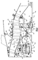
- a core housing 60 includes an inlet case 62 and an intermediate case 64 that respectively provide an inlet case flowpath 63 and a compressor case flowpath 65. Together, the inlet and compressor case flowpaths 63, 65, in part, define a core flowpath through the engine 20, which directs a core flow C.
- the intermediate case 64 includes multiple components, which includes the intermediate case portions 66, and the bearing support 68 in the example, which are removably secured to one another.
- the bearing support portion 68 has a first bearing 70 mounted thereto, which supports the inner shaft 40 for rotation relative to the intermediate case 64.
- the first bearing 70 is a ball bearing that constrains the inner shaft 40 against axial and radial movement at a forward portion of the inner shaft 40.
- the first bearing 70 is arranged within a bearing compartment 71.
- the inner shaft 40 is constructed of multiple components that include, for example, a main shaft 72, a hub 74 and a flex shaft 76, which are clamped together by a nut 80 in the example.
- the first bearing 70 is mounted on the hub 74.
- the flex shaft 76 includes first and second opposing ends 82, 84. The first end 82 is splined to the hub 74, and the second end 84 is splined to and supports a sun gear 86 of the geared architecture 48. Bellows 78 in the flex shaft 76 accommodate vibration in the geared architecture 48.
- the geared architecture includes star gears 88 arranged circumferentially about and intermeshing with the sun gear 86.
- a ring gear 90 is arranged circumferentially about and intermeshes with the star gears 88.
- a fan shaft 92 is connected to the ring gear 90 and the fan 42 ( Figure 1 ).
- a torque frame 94 supports the star gears 88 and grounds the star gears 88 to the housing 60. In operation, the inner shaft 40 rotationally drives the fan shaft 92 with the rotating ring gear 90 through the grounded star gears 88.
- the low pressure compressor 44 includes multiple compressor stages arranged between the inlet and intermediate case flowpaths 63, 65, for example, first and second compressor stages 98, 100, that are secured to the hub 74 by a rotor 96.
- the first bearing 70 is axially aligned with one of the first and second compressor stages 98, 100.
- a variable stator vane array 102 is arranged upstream from the first and second compressor stages 98, 100.
- Struts 104 are arranged upstream from the variable stator vane array 102.
- An array of fixed stator vanes 106 may be provided axially between the first and second compressor stages 98, 100.
- the inlet case 62 includes inlet case portions 108, and bearing support 110, which are removably secured to one another.
- the bearing support portion 110 and torque frame 94 are secured to the inlet case portion 108 at a joint 109.
- the bearing support portion 110 supports a second bearing 112, which is a rolling bearing in one example.
- the second bearing 112 is retained on the hub 74 by a nut 113, for example, and is arranged radially outward from the flex shaft 76 and radially between the torque frame 94 and flex shaft 76.
- the second bearing 112 is axially aligned with and radially inward of the variable stator vane array 102.
- the geared architecture 48 and the second bearing 112 are arranged in a lubrication compartment 114, which is separate from the bearing compartment 71 in the example.
- Figure 3 shows an embodiment 200, wherein there is a fan drive turbine 208 driving a shaft 206 to in turn drive a fan rotor 202.
- a gear reduction 204 may be positioned between the fan drive turbine 208 and the fan rotor 202. This gear reduction 204 may be structured and operate like the gear reduction disclosed above.
- a compressor rotor 210 is driven by an intermediate pressure turbine 212, and a second stage compressor rotor 214 is driven by a turbine rotor 216.
- a combustion section 218 is positioned intermediate the compressor rotor 214 and the turbine section 216.
- Figure 4 shows yet another embodiment 300 wherein a fan rotor 302 and a first stage compressor 304 rotate at a common speed.
- the gear reduction 306 (which may be structured as disclosed above) is intermediate the compressor rotor 304 and a shaft 308 which is driven by a low pressure turbine section.
Applications Claiming Priority (1)
| Application Number | Priority Date | Filing Date | Title |
|---|---|---|---|
| US14/570,091 US20150089959A1 (en) | 2012-01-31 | 2014-12-15 | Gas turbine engine shaft bearing configuration |
Publications (2)
| Publication Number | Publication Date |
|---|---|
| EP3081768A1 true EP3081768A1 (fr) | 2016-10-19 |
| EP3081768B1 EP3081768B1 (fr) | 2019-06-05 |
Family
ID=55024780
Family Applications (1)
| Application Number | Title | Priority Date | Filing Date |
|---|---|---|---|
| EP15199861.4A Active EP3081768B1 (fr) | 2014-12-15 | 2015-12-14 | Configuration de palier d'arbre de moteur à turbine à gaz |
Country Status (1)
| Country | Link |
|---|---|
| EP (1) | EP3081768B1 (fr) |
Families Citing this family (1)
| Publication number | Priority date | Publication date | Assignee | Title |
|---|---|---|---|---|
| US11280208B2 (en) | 2019-08-14 | 2022-03-22 | Pratt & Whitney Canada Corp. | Labyrinth seal assembly |
Citations (3)
| Publication number | Priority date | Publication date | Assignee | Title |
|---|---|---|---|---|
| US3792586A (en) * | 1973-01-22 | 1974-02-19 | Avco Corp | Bearing assembly systems |
| US20090074565A1 (en) * | 2004-12-01 | 2009-03-19 | Suciu Gabriel L | Turbine engine with differential gear driven fan and compressor |
| US8402741B1 (en) * | 2012-01-31 | 2013-03-26 | United Technologies Corporation | Gas turbine engine shaft bearing configuration |
-
2015
- 2015-12-14 EP EP15199861.4A patent/EP3081768B1/fr active Active
Patent Citations (3)
| Publication number | Priority date | Publication date | Assignee | Title |
|---|---|---|---|---|
| US3792586A (en) * | 1973-01-22 | 1974-02-19 | Avco Corp | Bearing assembly systems |
| US20090074565A1 (en) * | 2004-12-01 | 2009-03-19 | Suciu Gabriel L | Turbine engine with differential gear driven fan and compressor |
| US8402741B1 (en) * | 2012-01-31 | 2013-03-26 | United Technologies Corporation | Gas turbine engine shaft bearing configuration |
Also Published As
| Publication number | Publication date |
|---|---|
| EP3081768B1 (fr) | 2019-06-05 |
Similar Documents
| Publication | Publication Date | Title |
|---|---|---|
| US11566586B2 (en) | Gas turbine engine shaft bearing configuration | |
| US8511061B1 (en) | Gas turbine engine shaft bearing configuration | |
| CA2879756C (fr) | Soufflante a reducteur dotee d'un compresseur contrarotatif interne | |
| US9038366B2 (en) | LPC flowpath shape with gas turbine engine shaft bearing configuration | |
| EP2809890B1 (fr) | Agencement de paliers pour moteur à turbine à gaz | |
| EP3808964B1 (fr) | Turboréacteur à engrenages avec système de réduction d'engrenage non épicyclique | |
| US20150089959A1 (en) | Gas turbine engine shaft bearing configuration | |
| EP3054141B1 (fr) | Réduction d'engrenage pour turboréacteur à engrenage | |
| WO2015047489A1 (fr) | Configuration de palier d'arbre de moteur à turbine à gaz | |
| EP2809937B1 (fr) | Agencement de palier d'arbre de moteur de turbine à gaz | |
| EP3081768B1 (fr) | Configuration de palier d'arbre de moteur à turbine à gaz |
Legal Events
| Date | Code | Title | Description |
|---|---|---|---|
| PUAI | Public reference made under article 153(3) epc to a published international application that has entered the european phase |
Free format text: ORIGINAL CODE: 0009012 |
|
| AK | Designated contracting states |
Kind code of ref document: A1 Designated state(s): AL AT BE BG CH CY CZ DE DK EE ES FI FR GB GR HR HU IE IS IT LI LT LU LV MC MK MT NL NO PL PT RO RS SE SI SK SM TR |
|
| AX | Request for extension of the european patent |
Extension state: BA ME |
|
| RAP1 | Party data changed (applicant data changed or rights of an application transferred) |
Owner name: UNITED TECHNOLOGIES CORPORATION |
|
| STAA | Information on the status of an ep patent application or granted ep patent |
Free format text: STATUS: REQUEST FOR EXAMINATION WAS MADE |
|
| 17P | Request for examination filed |
Effective date: 20170419 |
|
| RBV | Designated contracting states (corrected) |
Designated state(s): AL AT BE BG CH CY CZ DE DK EE ES FI FR GB GR HR HU IE IS IT LI LT LU LV MC MK MT NL NO PL PT RO RS SE SI SK SM TR |
|
| STAA | Information on the status of an ep patent application or granted ep patent |
Free format text: STATUS: EXAMINATION IS IN PROGRESS |
|
| 17Q | First examination report despatched |
Effective date: 20171220 |
|
| GRAP | Despatch of communication of intention to grant a patent |
Free format text: ORIGINAL CODE: EPIDOSNIGR1 |
|
| STAA | Information on the status of an ep patent application or granted ep patent |
Free format text: STATUS: GRANT OF PATENT IS INTENDED |
|
| INTG | Intention to grant announced |
Effective date: 20181214 |
|
| GRAS | Grant fee paid |
Free format text: ORIGINAL CODE: EPIDOSNIGR3 |
|
| GRAA | (expected) grant |
Free format text: ORIGINAL CODE: 0009210 |
|
| STAA | Information on the status of an ep patent application or granted ep patent |
Free format text: STATUS: THE PATENT HAS BEEN GRANTED |
|
| AK | Designated contracting states |
Kind code of ref document: B1 Designated state(s): AL AT BE BG CH CY CZ DE DK EE ES FI FR GB GR HR HU IE IS IT LI LT LU LV MC MK MT NL NO PL PT RO RS SE SI SK SM TR |
|
| REG | Reference to a national code |
Ref country code: GB Ref legal event code: FG4D |
|
| REG | Reference to a national code |
Ref country code: CH Ref legal event code: EP |
|
| REG | Reference to a national code |
Ref country code: AT Ref legal event code: REF Ref document number: 1140182 Country of ref document: AT Kind code of ref document: T Effective date: 20190615 |
|
| REG | Reference to a national code |
Ref country code: IE Ref legal event code: FG4D |
|
| REG | Reference to a national code |
Ref country code: DE Ref legal event code: R096 Ref document number: 602015031321 Country of ref document: DE |
|
| REG | Reference to a national code |
Ref country code: NL Ref legal event code: MP Effective date: 20190605 |
|
| REG | Reference to a national code |
Ref country code: LT Ref legal event code: MG4D |
|
| PG25 | Lapsed in a contracting state [announced via postgrant information from national office to epo] |
Ref country code: FI Free format text: LAPSE BECAUSE OF FAILURE TO SUBMIT A TRANSLATION OF THE DESCRIPTION OR TO PAY THE FEE WITHIN THE PRESCRIBED TIME-LIMIT Effective date: 20190605 Ref country code: SE Free format text: LAPSE BECAUSE OF FAILURE TO SUBMIT A TRANSLATION OF THE DESCRIPTION OR TO PAY THE FEE WITHIN THE PRESCRIBED TIME-LIMIT Effective date: 20190605 Ref country code: LT Free format text: LAPSE BECAUSE OF FAILURE TO SUBMIT A TRANSLATION OF THE DESCRIPTION OR TO PAY THE FEE WITHIN THE PRESCRIBED TIME-LIMIT Effective date: 20190605 Ref country code: ES Free format text: LAPSE BECAUSE OF FAILURE TO SUBMIT A TRANSLATION OF THE DESCRIPTION OR TO PAY THE FEE WITHIN THE PRESCRIBED TIME-LIMIT Effective date: 20190605 Ref country code: HR Free format text: LAPSE BECAUSE OF FAILURE TO SUBMIT A TRANSLATION OF THE DESCRIPTION OR TO PAY THE FEE WITHIN THE PRESCRIBED TIME-LIMIT Effective date: 20190605 Ref country code: AL Free format text: LAPSE BECAUSE OF FAILURE TO SUBMIT A TRANSLATION OF THE DESCRIPTION OR TO PAY THE FEE WITHIN THE PRESCRIBED TIME-LIMIT Effective date: 20190605 Ref country code: NO Free format text: LAPSE BECAUSE OF FAILURE TO SUBMIT A TRANSLATION OF THE DESCRIPTION OR TO PAY THE FEE WITHIN THE PRESCRIBED TIME-LIMIT Effective date: 20190905 |
|
| PG25 | Lapsed in a contracting state [announced via postgrant information from national office to epo] |
Ref country code: GR Free format text: LAPSE BECAUSE OF FAILURE TO SUBMIT A TRANSLATION OF THE DESCRIPTION OR TO PAY THE FEE WITHIN THE PRESCRIBED TIME-LIMIT Effective date: 20190906 Ref country code: LV Free format text: LAPSE BECAUSE OF FAILURE TO SUBMIT A TRANSLATION OF THE DESCRIPTION OR TO PAY THE FEE WITHIN THE PRESCRIBED TIME-LIMIT Effective date: 20190605 Ref country code: BG Free format text: LAPSE BECAUSE OF FAILURE TO SUBMIT A TRANSLATION OF THE DESCRIPTION OR TO PAY THE FEE WITHIN THE PRESCRIBED TIME-LIMIT Effective date: 20190905 Ref country code: RS Free format text: LAPSE BECAUSE OF FAILURE TO SUBMIT A TRANSLATION OF THE DESCRIPTION OR TO PAY THE FEE WITHIN THE PRESCRIBED TIME-LIMIT Effective date: 20190605 |
|
| REG | Reference to a national code |
Ref country code: AT Ref legal event code: MK05 Ref document number: 1140182 Country of ref document: AT Kind code of ref document: T Effective date: 20190605 |
|
| PG25 | Lapsed in a contracting state [announced via postgrant information from national office to epo] |
Ref country code: RO Free format text: LAPSE BECAUSE OF FAILURE TO SUBMIT A TRANSLATION OF THE DESCRIPTION OR TO PAY THE FEE WITHIN THE PRESCRIBED TIME-LIMIT Effective date: 20190605 Ref country code: SK Free format text: LAPSE BECAUSE OF FAILURE TO SUBMIT A TRANSLATION OF THE DESCRIPTION OR TO PAY THE FEE WITHIN THE PRESCRIBED TIME-LIMIT Effective date: 20190605 Ref country code: CZ Free format text: LAPSE BECAUSE OF FAILURE TO SUBMIT A TRANSLATION OF THE DESCRIPTION OR TO PAY THE FEE WITHIN THE PRESCRIBED TIME-LIMIT Effective date: 20190605 Ref country code: NL Free format text: LAPSE BECAUSE OF FAILURE TO SUBMIT A TRANSLATION OF THE DESCRIPTION OR TO PAY THE FEE WITHIN THE PRESCRIBED TIME-LIMIT Effective date: 20190605 Ref country code: PT Free format text: LAPSE BECAUSE OF FAILURE TO SUBMIT A TRANSLATION OF THE DESCRIPTION OR TO PAY THE FEE WITHIN THE PRESCRIBED TIME-LIMIT Effective date: 20191007 Ref country code: AT Free format text: LAPSE BECAUSE OF FAILURE TO SUBMIT A TRANSLATION OF THE DESCRIPTION OR TO PAY THE FEE WITHIN THE PRESCRIBED TIME-LIMIT Effective date: 20190605 Ref country code: EE Free format text: LAPSE BECAUSE OF FAILURE TO SUBMIT A TRANSLATION OF THE DESCRIPTION OR TO PAY THE FEE WITHIN THE PRESCRIBED TIME-LIMIT Effective date: 20190605 |
|
| PG25 | Lapsed in a contracting state [announced via postgrant information from national office to epo] |
Ref country code: IT Free format text: LAPSE BECAUSE OF FAILURE TO SUBMIT A TRANSLATION OF THE DESCRIPTION OR TO PAY THE FEE WITHIN THE PRESCRIBED TIME-LIMIT Effective date: 20190605 Ref country code: SM Free format text: LAPSE BECAUSE OF FAILURE TO SUBMIT A TRANSLATION OF THE DESCRIPTION OR TO PAY THE FEE WITHIN THE PRESCRIBED TIME-LIMIT Effective date: 20190605 Ref country code: IS Free format text: LAPSE BECAUSE OF FAILURE TO SUBMIT A TRANSLATION OF THE DESCRIPTION OR TO PAY THE FEE WITHIN THE PRESCRIBED TIME-LIMIT Effective date: 20191005 |
|
| REG | Reference to a national code |
Ref country code: DE Ref legal event code: R097 Ref document number: 602015031321 Country of ref document: DE |
|
| PG25 | Lapsed in a contracting state [announced via postgrant information from national office to epo] |
Ref country code: TR Free format text: LAPSE BECAUSE OF FAILURE TO SUBMIT A TRANSLATION OF THE DESCRIPTION OR TO PAY THE FEE WITHIN THE PRESCRIBED TIME-LIMIT Effective date: 20190605 |
|
| PLBE | No opposition filed within time limit |
Free format text: ORIGINAL CODE: 0009261 |
|
| STAA | Information on the status of an ep patent application or granted ep patent |
Free format text: STATUS: NO OPPOSITION FILED WITHIN TIME LIMIT |
|
| PG25 | Lapsed in a contracting state [announced via postgrant information from national office to epo] |
Ref country code: DK Free format text: LAPSE BECAUSE OF FAILURE TO SUBMIT A TRANSLATION OF THE DESCRIPTION OR TO PAY THE FEE WITHIN THE PRESCRIBED TIME-LIMIT Effective date: 20190605 Ref country code: PL Free format text: LAPSE BECAUSE OF FAILURE TO SUBMIT A TRANSLATION OF THE DESCRIPTION OR TO PAY THE FEE WITHIN THE PRESCRIBED TIME-LIMIT Effective date: 20190605 |
|
| 26N | No opposition filed |
Effective date: 20200306 |
|
| PG25 | Lapsed in a contracting state [announced via postgrant information from national office to epo] |
Ref country code: SI Free format text: LAPSE BECAUSE OF FAILURE TO SUBMIT A TRANSLATION OF THE DESCRIPTION OR TO PAY THE FEE WITHIN THE PRESCRIBED TIME-LIMIT Effective date: 20190605 |
|
| REG | Reference to a national code |
Ref country code: CH Ref legal event code: PL |
|
| REG | Reference to a national code |
Ref country code: BE Ref legal event code: MM Effective date: 20191231 |
|
| PG25 | Lapsed in a contracting state [announced via postgrant information from national office to epo] |
Ref country code: MC Free format text: LAPSE BECAUSE OF FAILURE TO SUBMIT A TRANSLATION OF THE DESCRIPTION OR TO PAY THE FEE WITHIN THE PRESCRIBED TIME-LIMIT Effective date: 20190605 |
|
| PG25 | Lapsed in a contracting state [announced via postgrant information from national office to epo] |
Ref country code: LU Free format text: LAPSE BECAUSE OF NON-PAYMENT OF DUE FEES Effective date: 20191214 Ref country code: IE Free format text: LAPSE BECAUSE OF NON-PAYMENT OF DUE FEES Effective date: 20191214 |
|
| PG25 | Lapsed in a contracting state [announced via postgrant information from national office to epo] |
Ref country code: LI Free format text: LAPSE BECAUSE OF NON-PAYMENT OF DUE FEES Effective date: 20191231 Ref country code: BE Free format text: LAPSE BECAUSE OF NON-PAYMENT OF DUE FEES Effective date: 20191231 Ref country code: CH Free format text: LAPSE BECAUSE OF NON-PAYMENT OF DUE FEES Effective date: 20191231 |
|
| PG25 | Lapsed in a contracting state [announced via postgrant information from national office to epo] |
Ref country code: CY Free format text: LAPSE BECAUSE OF FAILURE TO SUBMIT A TRANSLATION OF THE DESCRIPTION OR TO PAY THE FEE WITHIN THE PRESCRIBED TIME-LIMIT Effective date: 20190605 |
|
| PG25 | Lapsed in a contracting state [announced via postgrant information from national office to epo] |
Ref country code: MT Free format text: LAPSE BECAUSE OF FAILURE TO SUBMIT A TRANSLATION OF THE DESCRIPTION OR TO PAY THE FEE WITHIN THE PRESCRIBED TIME-LIMIT Effective date: 20190605 Ref country code: HU Free format text: LAPSE BECAUSE OF FAILURE TO SUBMIT A TRANSLATION OF THE DESCRIPTION OR TO PAY THE FEE WITHIN THE PRESCRIBED TIME-LIMIT; INVALID AB INITIO Effective date: 20151214 |
|
| PG25 | Lapsed in a contracting state [announced via postgrant information from national office to epo] |
Ref country code: MK Free format text: LAPSE BECAUSE OF FAILURE TO SUBMIT A TRANSLATION OF THE DESCRIPTION OR TO PAY THE FEE WITHIN THE PRESCRIBED TIME-LIMIT Effective date: 20190605 |
|
| REG | Reference to a national code |
Ref country code: DE Ref legal event code: R081 Ref document number: 602015031321 Country of ref document: DE Owner name: RAYTHEON TECHNOLOGIES CORPORATION (N.D.GES.D.S, US Free format text: FORMER OWNER: UNITED TECHNOLOGIES CORPORATION, FARMINGTON, CONN., US |
|
| P01 | Opt-out of the competence of the unified patent court (upc) registered |
Effective date: 20230630 |
|
| PGFP | Annual fee paid to national office [announced via postgrant information from national office to epo] |
Ref country code: GB Payment date: 20231121 Year of fee payment: 9 |
|
| PGFP | Annual fee paid to national office [announced via postgrant information from national office to epo] |
Ref country code: FR Payment date: 20231122 Year of fee payment: 9 Ref country code: DE Payment date: 20231121 Year of fee payment: 9 |