EP3081760A1 - Heat shield, systems and methods - Google Patents
Heat shield, systems and methods Download PDFInfo
- Publication number
- EP3081760A1 EP3081760A1 EP16164697.1A EP16164697A EP3081760A1 EP 3081760 A1 EP3081760 A1 EP 3081760A1 EP 16164697 A EP16164697 A EP 16164697A EP 3081760 A1 EP3081760 A1 EP 3081760A1
- Authority
- EP
- European Patent Office
- Prior art keywords
- heat shield
- oil tube
- fitting
- top portion
- various embodiments
- Prior art date
- Legal status (The legal status is an assumption and is not a legal conclusion. Google has not performed a legal analysis and makes no representation as to the accuracy of the status listed.)
- Granted
Links
Images



Classifications
-
- F—MECHANICAL ENGINEERING; LIGHTING; HEATING; WEAPONS; BLASTING
- F01—MACHINES OR ENGINES IN GENERAL; ENGINE PLANTS IN GENERAL; STEAM ENGINES
- F01D—NON-POSITIVE DISPLACEMENT MACHINES OR ENGINES, e.g. STEAM TURBINES
- F01D25/00—Component parts, details, or accessories, not provided for in, or of interest apart from, other groups
- F01D25/18—Lubricating arrangements
-
- F—MECHANICAL ENGINEERING; LIGHTING; HEATING; WEAPONS; BLASTING
- F01—MACHINES OR ENGINES IN GENERAL; ENGINE PLANTS IN GENERAL; STEAM ENGINES
- F01D—NON-POSITIVE DISPLACEMENT MACHINES OR ENGINES, e.g. STEAM TURBINES
- F01D25/00—Component parts, details, or accessories, not provided for in, or of interest apart from, other groups
- F01D25/16—Arrangement of bearings; Supporting or mounting bearings in casings
- F01D25/162—Bearing supports
-
- F—MECHANICAL ENGINEERING; LIGHTING; HEATING; WEAPONS; BLASTING
- F01—MACHINES OR ENGINES IN GENERAL; ENGINE PLANTS IN GENERAL; STEAM ENGINES
- F01D—NON-POSITIVE DISPLACEMENT MACHINES OR ENGINES, e.g. STEAM TURBINES
- F01D25/00—Component parts, details, or accessories, not provided for in, or of interest apart from, other groups
- F01D25/28—Supporting or mounting arrangements, e.g. for turbine casing
-
- F—MECHANICAL ENGINEERING; LIGHTING; HEATING; WEAPONS; BLASTING
- F01—MACHINES OR ENGINES IN GENERAL; ENGINE PLANTS IN GENERAL; STEAM ENGINES
- F01D—NON-POSITIVE DISPLACEMENT MACHINES OR ENGINES, e.g. STEAM TURBINES
- F01D9/00—Stators
- F01D9/02—Nozzles; Nozzle boxes; Stator blades; Guide conduits, e.g. individual nozzles
-
- F—MECHANICAL ENGINEERING; LIGHTING; HEATING; WEAPONS; BLASTING
- F01—MACHINES OR ENGINES IN GENERAL; ENGINE PLANTS IN GENERAL; STEAM ENGINES
- F01D—NON-POSITIVE DISPLACEMENT MACHINES OR ENGINES, e.g. STEAM TURBINES
- F01D9/00—Stators
- F01D9/06—Fluid supply conduits to nozzles or the like
- F01D9/065—Fluid supply or removal conduits traversing the working fluid flow, e.g. for lubrication-, cooling-, or sealing fluids
-
- F—MECHANICAL ENGINEERING; LIGHTING; HEATING; WEAPONS; BLASTING
- F01—MACHINES OR ENGINES IN GENERAL; ENGINE PLANTS IN GENERAL; STEAM ENGINES
- F01M—LUBRICATING OF MACHINES OR ENGINES IN GENERAL; LUBRICATING INTERNAL COMBUSTION ENGINES; CRANKCASE VENTILATING
- F01M11/00—Component parts, details or accessories, not provided for in, or of interest apart from, groups F01M1/00 - F01M9/00
- F01M11/02—Arrangements of lubricant conduits
-
- F—MECHANICAL ENGINEERING; LIGHTING; HEATING; WEAPONS; BLASTING
- F05—INDEXING SCHEMES RELATING TO ENGINES OR PUMPS IN VARIOUS SUBCLASSES OF CLASSES F01-F04
- F05D—INDEXING SCHEME FOR ASPECTS RELATING TO NON-POSITIVE-DISPLACEMENT MACHINES OR ENGINES, GAS-TURBINES OR JET-PROPULSION PLANTS
- F05D2230/00—Manufacture
-
- F—MECHANICAL ENGINEERING; LIGHTING; HEATING; WEAPONS; BLASTING
- F05—INDEXING SCHEMES RELATING TO ENGINES OR PUMPS IN VARIOUS SUBCLASSES OF CLASSES F01-F04
- F05D—INDEXING SCHEME FOR ASPECTS RELATING TO NON-POSITIVE-DISPLACEMENT MACHINES OR ENGINES, GAS-TURBINES OR JET-PROPULSION PLANTS
- F05D2230/00—Manufacture
- F05D2230/50—Building or constructing in particular ways
- F05D2230/54—Building or constructing in particular ways by sheet metal manufacturing
-
- F—MECHANICAL ENGINEERING; LIGHTING; HEATING; WEAPONS; BLASTING
- F05—INDEXING SCHEMES RELATING TO ENGINES OR PUMPS IN VARIOUS SUBCLASSES OF CLASSES F01-F04
- F05D—INDEXING SCHEME FOR ASPECTS RELATING TO NON-POSITIVE-DISPLACEMENT MACHINES OR ENGINES, GAS-TURBINES OR JET-PROPULSION PLANTS
- F05D2240/00—Components
- F05D2240/10—Stators
- F05D2240/12—Fluid guiding means, e.g. vanes
-
- F—MECHANICAL ENGINEERING; LIGHTING; HEATING; WEAPONS; BLASTING
- F05—INDEXING SCHEMES RELATING TO ENGINES OR PUMPS IN VARIOUS SUBCLASSES OF CLASSES F01-F04
- F05D—INDEXING SCHEME FOR ASPECTS RELATING TO NON-POSITIVE-DISPLACEMENT MACHINES OR ENGINES, GAS-TURBINES OR JET-PROPULSION PLANTS
- F05D2240/00—Components
- F05D2240/10—Stators
- F05D2240/15—Heat shield
-
- F—MECHANICAL ENGINEERING; LIGHTING; HEATING; WEAPONS; BLASTING
- F05—INDEXING SCHEMES RELATING TO ENGINES OR PUMPS IN VARIOUS SUBCLASSES OF CLASSES F01-F04
- F05D—INDEXING SCHEME FOR ASPECTS RELATING TO NON-POSITIVE-DISPLACEMENT MACHINES OR ENGINES, GAS-TURBINES OR JET-PROPULSION PLANTS
- F05D2240/00—Components
- F05D2240/50—Bearings
-
- F—MECHANICAL ENGINEERING; LIGHTING; HEATING; WEAPONS; BLASTING
- F05—INDEXING SCHEMES RELATING TO ENGINES OR PUMPS IN VARIOUS SUBCLASSES OF CLASSES F01-F04
- F05D—INDEXING SCHEME FOR ASPECTS RELATING TO NON-POSITIVE-DISPLACEMENT MACHINES OR ENGINES, GAS-TURBINES OR JET-PROPULSION PLANTS
- F05D2250/00—Geometry
- F05D2250/10—Two-dimensional
- F05D2250/11—Two-dimensional triangular
-
- F—MECHANICAL ENGINEERING; LIGHTING; HEATING; WEAPONS; BLASTING
- F05—INDEXING SCHEMES RELATING TO ENGINES OR PUMPS IN VARIOUS SUBCLASSES OF CLASSES F01-F04
- F05D—INDEXING SCHEME FOR ASPECTS RELATING TO NON-POSITIVE-DISPLACEMENT MACHINES OR ENGINES, GAS-TURBINES OR JET-PROPULSION PLANTS
- F05D2260/00—Function
- F05D2260/20—Heat transfer, e.g. cooling
- F05D2260/231—Preventing heat transfer
-
- F—MECHANICAL ENGINEERING; LIGHTING; HEATING; WEAPONS; BLASTING
- F05—INDEXING SCHEMES RELATING TO ENGINES OR PUMPS IN VARIOUS SUBCLASSES OF CLASSES F01-F04
- F05D—INDEXING SCHEME FOR ASPECTS RELATING TO NON-POSITIVE-DISPLACEMENT MACHINES OR ENGINES, GAS-TURBINES OR JET-PROPULSION PLANTS
- F05D2260/00—Function
- F05D2260/98—Lubrication
-
- Y—GENERAL TAGGING OF NEW TECHNOLOGICAL DEVELOPMENTS; GENERAL TAGGING OF CROSS-SECTIONAL TECHNOLOGIES SPANNING OVER SEVERAL SECTIONS OF THE IPC; TECHNICAL SUBJECTS COVERED BY FORMER USPC CROSS-REFERENCE ART COLLECTIONS [XRACs] AND DIGESTS
- Y02—TECHNOLOGIES OR APPLICATIONS FOR MITIGATION OR ADAPTATION AGAINST CLIMATE CHANGE
- Y02T—CLIMATE CHANGE MITIGATION TECHNOLOGIES RELATED TO TRANSPORTATION
- Y02T50/00—Aeronautics or air transport
- Y02T50/60—Efficient propulsion technologies, e.g. for aircraft
Definitions
- This disclosure relates to a gas turbine engine, and more particularly to heat shields for oil tube fittings.
- Engine oil tubes and fittings may be subjected to relatively high temperatures. Once subjected to excessive heating, oil may undergo coking. Oil coking may cause solid oil deposits to form within oil tubes, causing undesirable effects such as blocked passageways and filters.
- a heat shield is described herein, in accordance with various embodiments.
- a heat shield may comprise a base portion, a top portion, and a tapered portion extending between the top portion and the bottom portion.
- the base portion may comprise a sheet metal bounding a triangular void.
- the top portion may comprise a sheet metal bounding an ovular void.
- a lubricating assembly may include an oil tube, a fitting, and a heat shield.
- the fitting may be configured to be attached to the oil tube.
- the heat shield may be configured to be attached to the oil tube.
- the heat shield comprises a base portion, wherein the base portion bounds a void; a top portion, wherein the top portion bounds a void; and a tapered portion, wherein the tapered portion extends between the base portion and the top portion.
- the oil tube may be a dual wall oil tube comprising an inner wall and an outer wall.
- the heat shield is configured to at least partially encase the fitting.
- the heat shield is configured to prevent heat transfer between the fitting and surrounding air.
- the heat shield and the fitting are separated by a gap.
- the top portion comprises a smaller cross-sectional area than the base portion.
- the base portion bounds a triangular void.
- the top portion bounds an ovular void.
- the heat shield is manufactured via a hydro-forming process.
- the heat shield comprises at least one of a nickel-chromium based alloy and a stainless steel.
- a method of cooling an oil tube fitting is disclosed herein, in accordance with various embodiments.
- the method of cooling an oil tube fitting may include disposing a heat shield about an oil tube.
- the heat shield When in the installed position, the heat shield may at least partially encase an oil tube fitting.
- the heat shield When in the installed position and during operation, the heat shield may be configured to prevent heat transfer between the oil tube fitting and surrounding hot air.
- the heat shield When in the installed position, the heat shield may be configured to be separated from the oil tube fitting by a gap.
- Introducing a heat shield may prevent oil tube fittings from excessively heating, preventing oil coking.
- any reference to attached, fixed, connected or the like may include permanent, removable, temporary, partial, full and/or any other possible attachment option. Additionally, any reference to without contact (or similar phrases) may also include reduced contact or minimal contact. Surface shading lines may be used throughout the figures to denote different parts but not necessarily to denote the same or different materials. In some cases, reference coordinates may be specific to each figure.
- tail refers to the direction associated with the tail (e.g., the back end) of an aircraft, or generally, to the direction of exhaust of the gas turbine.
- forward refers to the direction associated with the nose (e.g., the front end) of an aircraft, or generally, to the direction of flight or motion.
- distal refers to the direction radially outward, or generally, away from the axis of rotation of a turbine engine.
- proximal refers to a direction radially inward, or generally, towards the axis of rotation of a turbine engine.
- Gas turbine engine 20 may be a two-spool turbofan that generally incorporates a fan section 22, a compressor section 24, a combustor section 26 and a turbine section 28.
- Alternative engines may include, for example, an augmenter section among other systems or features.
- fan section 22 can drive air along a bypass flow-path B while compressor section 24 can drive air for compression and communication into combustor section 26 then expansion through turbine section 28.
- turbofan gas turbine engine 20 depicted as a turbofan gas turbine engine 20 herein, it should be understood that the concepts described herein are not limited to use with turbofans as the teachings may be applied to other types of gas turbine engines including three-spool architectures.
- Gas turbine engine 20 may generally comprise a low speed spool 30 and a high speed spool 32 mounted for rotation about an engine central longitudinal axis A-A' relative to an engine static structure 36 via one or more bearing systems 38 (shown as bearing system 38-1 and bearing system 38-2). It should be understood that various bearing systems 38 at various locations may alternatively or additionally be provided, including for example, bearing system 38, bearing system 38-1, and bearing system 38-2.
- Low speed spool 30 may generally comprise an inner shaft 40 that interconnects a fan 42, a low pressure (or first) compressor section 44 (also referred to a low pressure compressor) and a low pressure (or first) turbine section 46.
- Inner shaft 40 may be connected to fan 42 through a geared architecture 48 that can drive fan 42 at a lower speed than low speed spool 30.
- Geared architecture 48 may comprise a gear assembly 60 enclosed within a gear housing 62.
- Gear assembly 60 couples inner shaft 40 to a rotating fan structure.
- High speed spool 32 may comprise an outer shaft 50 that interconnects a high pressure compressor 52 (e.g., a second compressor section) and high pressure (or second) turbine section (“HPT”) 54.
- HPT high pressure turbine section
- a combustor 56 may be located between high pressure compressor 52 and HPT 54.
- a mid-turbine frame 57 of engine static structure 36 may be located generally between HPT 54 and low pressure turbine 46.
- Mid-turbine frame 57 may support one or more bearing systems 38 in turbine section 28.
- Inner shaft 40 and outer shaft 50 may be concentric and rotate via bearing systems 38 about the engine central longitudinal axis A-A', which is collinear with their longitudinal axes.
- a "high pressure" compressor or turbine experiences a higher pressure than a corresponding "low pressure” compressor or turbine.
- the core airflow may be compressed by low pressure compressor 44 then high pressure compressor 52, mixed and burned with fuel in combustor 56, then expanded over HPT 54 and low pressure turbine 46.
- Mid-turbine frame 57 includes airfoils 59 which are in the core airflow path.
- Low pressure turbine 46 and HPT 54 rotationally drive the respective low speed spool 30 and high speed spool 32 in response to the expansion.
- Gas turbine engine 20 may be, for example, a high-bypass geared aircraft engine. In various embodiments, the bypass ratio of gas turbine engine 20 may be greater than about six (6). In various embodiments, the bypass ratio of gas turbine engine 20 may be greater than ten (10).
- geared architecture 48 may be an epicyclic gear train, such as a star gear system (sun gear in meshing engagement with a plurality of star gears supported by a carrier and in meshing engagement with a ring gear) or other gear system. Geared architecture 48 may have a gear reduction ratio of greater than about 2.3 and low pressure turbine 46 may have a pressure ratio that is greater than about 5. In various embodiments, the bypass ratio of gas turbine engine 20 is greater than about ten (10:1).
- the diameter of fan 42 may be significantly larger than that of the low pressure compressor 44, and the low pressure turbine 46 may have a pressure ratio that is greater than about (5:1). Low pressure turbine 46 pressure ratio may be measured prior to inlet of low pressure turbine 46 as related to the pressure at the outlet of low pressure turbine 46 prior to an exhaust nozzle. It should be understood, however, that the above parameters are exemplary of various embodiments of a suitable geared architecture engine and that the present disclosure contemplates other gas turbine engines including direct drive turbofans.
- MTF assembly 257 may include bearing compartment 238, outer case 266, and inner case 268.
- MTF vane 259 may be located between inner case 268 and outer case 266.
- Oil tube fitting 212 may be attached to a portion of bearing compartment 238.
- Oil tube 206 may extend between outer case 266 and oil tube fitting 212.
- Oil 214 may be located within oil tube 206.
- Oil 214 may be used to lubricate at least a portion of bearing compartment 238.
- Oil tube 206 may be located at least partially within MTF vane 259.
- Sleeve 210 may encase at least a portion of oil tube 206.
- Oil tube fitting heat shield (also referred to herein as heat shield) 202 may be located between MTF vane 259 and oil tube fitting 212.
- Heat waves 218 may radiate from MTF vane 259.
- heat waves may radiate to other nearby components which may cause the nearby components to increase in temperature.
- the nearby components may transfer heat conductively to other adjacent components and/or fluids.
- heat waves may radiate from MTF vane 259 to oil tube 206 which may convectively transfer heat from MTF vane 259 to oil tube 206. Heat may be conductively transferred to oil located inside oil tube 206.
- oil exceeds various threshold temperatures, it may undergo severe oxidative and thermal breakdown which may cause solid deposits to form.
- Heat shield 202 may be configured to block heat waves 218 radiating from MTF vane 259 from directly impinging on oil tube fitting 212. Furthermore, heat shield 202 may help minimize convective heat transfer from hot air surrounding oil tube fitting 212. Accordingly, heat shield 202 may help block heat from being transferred to oil tube fitting 212. In various embodiments, heat shield 202 may help prevent oil from coking within oil tube fitting 212. Sleeve 210 may be configured to block radiating heat waves from MTF vane 259 from impinging on oil tube 206.
- oil tube 206 may comprise an inner tube 207 and an outer tube 208. Accordingly, oil tube 206 may be referred to as a dual wall tube. Inner tube 207 may be enclosed by outer tube 208. There may be a space between inner tube 207 and outer tube 208 which may be occupied by air. The outer tube 208 may be configured to contain oil within outer tube 208 in the event that there is an oil leak from inner tube 207. Outer tube 208 may be configured to prevent heat transfer from surrounding hot air to inner tube 207. Oil tube 206 may be configured to attach to oil tube fitting 212. Oil tube 206 may be attached to oil tube fitting 212 via weld, solder, braze, or any other suitable method.
- Heat shield 202 may comprise a base portion 204 and a top portion 203.
- Top portion 203 of heat shield 202 may be configured to attach to oil tube 206.
- Top portion 203 of heat shield 202 may be configured to attach to oil tube 206 via weld, solder, braze, or any other suitable method.
- Top portion 203 of heat shield 202 may be configured to attach to oil tube 206 in close proximity to an end of oil tube 206.
- Top portion 203 of heat shield 202 may be configured to attach to oil tube 206 in close proximity to a proximal end of oil tube 206.
- Top portion 203 of heat shield 202 may be configured to attach to oil tube 206 such that there is a small gap between heat shield 202 and sleeve 210.
- Base portion 204 of heat shield 202 may be configured to at least partially encase oil tube fitting 212.
- various components of MTF assemblies may comprise various materials.
- Various components, including heat shield 202 may comprise a high temperature metal (e.g., an austenitic nickel-chromium-based alloy such as INCONEL), a high temperature composite, and/or the like.
- heat shield 202 may comprise a high temperature stainless steel.
- heat shield 202 may comprise a wall thickness "T.”
- heat shield 202 may be manufactured via a hydro-forming process.
- Wall thickness "T” may be chosen according to various design considerations. In various embodiments, wall thickness "T” may be between 0.010 in (0.25 mm) and 0.030 in (0.76 mm) in thick.
- sheet metal of a preferred wall thickness may be chosen to be hydro-formed to the desired heat shield geometry. For example, if a heat shield comprising a wall thickness of 0.5 mm is desired, a piece of sheet metal comprising a wall thickness of 0.5 mm may be used and formed into the desired geometry using high pressure hydraulic fluid to press the sheet metal into a die in a process known as hydro-forming. In various embodiments, a single piece of sheet metal may be hydro-formed into heat shield 202. In various embodiments, two or more pieces of sheet metal may be hydro-formed into different geometries and welded together to form heat shield 202.
- FIG 3A and FIG 3B elements with like element numbering as depicted in FIG 2A and FIG 2B , are intended to be the same and certain properties, including material properties, will not be repeated for the sake of clarity.
- oil tube fitting 312 may be separated from heat shield 302 by a gap "G".
- Heat shield 302 may be configured to be separated from oil tube fitting 312 by gap "G” such that a conductive thermal path does not exist between heat shield 302 and oil tube fitting 312.
- Gap “G” may be configured to be minimal while allowing thermal expansion of heat shield 302 and oil tube fitting 312 without creating a thermal conduction path between heat shield 302 and oil tube fitting 312.
- Minimizing gap “G” may allow heat shield 302 to more effectively minimize convective heat transfer between oil tube fitting 312 and surrounding hot air.
- Minimizing gap “G” may allow heat shield 302 to more effectively minimize convective heat transfer between oil tube fitting 312 and radiated heat from an adjacent MTF vane.
- the base portion 304 of heat shield 302 may comprise a triangular geometry.
- FIG 3B illustrates the base portion 304 of heat shield 302, wherein the base portion bounds a triangular void.
- the base portion 304 of heat shield 302 may comprise one of a square, rectangular, oblong, round, elliptical, or any other geometry.
- the geometry of the base portion 304 of heat shield 302 may be driven by the geometry of oil tube fitting 312. Accordingly, the geometry of oil tube fitting 312 and base portion 304 may be complementary.
- the top portion 303 of heat shield 302 may comprise an ovular geometry.
- FIG 3B illustrates the top portion 303 of heat shield 302, wherein the top portion 303 bounds an ovular void.
- the top portion 303 of heat shield 302 may comprise a square, rectangular, oblong, round, elliptical, or any other geometry.
- the geometry of the top portion 303 of heat shield 302 may be driven by the geometry of oil tube 306. Accordingly, the geometry of oil tube 306 and top portion 303 may be complementary.
- the geometry of top portion 303 and base portion 304 may be complementary.
- the geometry of top portion 303 and base portion 304 may be different.
- top portion 303 may be connected to base portion 304 by a tapered portion 305.
- top portion 303 may comprise a cross-sectional area.
- the cross-sectional area of top portion 303 may be the area of a slice of top portion 303 taken along line B-B in the x-z plane according to the coordinates provided in FIG 3A .
- the cross-sectional area of top portion 303 may be best visualized by viewing top portion 303 from the top view as shown in FIG 3B .
- base portion 304 may comprise a cross-sectional area.
- the cross-sectional area of base portion 304 may be the area of a slice of base portion 304 taken along line C-C in the x-z plane according to the coordinates provided in FIG 3A .
- the cross-sectional area of base portion 304 may be best visualized by viewing base portion 304 from the top view as shown in FIG 3B .
- a method of cooling an oil tube fitting is disclosed herein, in accordance with various embodiments.
- the method of cooling an oil tube fitting may include disposing a heat shield about an oil tube.
- the heat shield When in the installed position, the heat shield may at least partially encase an oil tube fitting.
- the heat shield When in the installed position and during operation, the heat shield may be configured to prevent heat transfer between the oil tube fitting and surrounding hot air.
- the heat shield When in the installed position, the heat shield may be configured to be separated from the oil tube fitting by a gap.
- references to "one embodiment”, “an embodiment”, “various embodiments”, etc. indicate that the embodiment described may include a particular feature, structure, or characteristic, but every embodiment may not necessarily include the particular feature, structure, or characteristic. Moreover, such phrases are not necessarily referring to the same embodiment. Further, when a particular feature, structure, or characteristic is described in connection with an embodiment, it is submitted that it is within the knowledge of one skilled in the art to affect such feature, structure, or characteristic in connection with other embodiments whether or not explicitly described. After reading the description, it will be apparent to one skilled in the relevant art(s) how to implement the disclosure in alternative embodiments.
Landscapes
- Engineering & Computer Science (AREA)
- Mechanical Engineering (AREA)
- General Engineering & Computer Science (AREA)
- Physics & Mathematics (AREA)
- Fluid Mechanics (AREA)
- Turbine Rotor Nozzle Sealing (AREA)
- Structures Of Non-Positive Displacement Pumps (AREA)
- Heat-Exchange Devices With Radiators And Conduit Assemblies (AREA)
Abstract
Description
- This disclosure relates to a gas turbine engine, and more particularly to heat shields for oil tube fittings.
- Engine oil tubes and fittings may be subjected to relatively high temperatures. Once subjected to excessive heating, oil may undergo coking. Oil coking may cause solid oil deposits to form within oil tubes, causing undesirable effects such as blocked passageways and filters.
- A heat shield is described herein, in accordance with various embodiments. A heat shield may comprise a base portion, a top portion, and a tapered portion extending between the top portion and the bottom portion. The base portion may comprise a sheet metal bounding a triangular void. The top portion may comprise a sheet metal bounding an ovular void.
- A lubricating assembly is described herein, in accordance with various embodiments. A lubricating assembly may include an oil tube, a fitting, and a heat shield. The fitting may be configured to be attached to the oil tube. The heat shield may be configured to be attached to the oil tube. The heat shield comprises a base portion, wherein the base portion bounds a void; a top portion, wherein the top portion bounds a void; and a tapered portion, wherein the tapered portion extends between the base portion and the top portion.
- Although not presently claimed, the Applicant reserves the right to claim this lubricating assembly independently, either in the present application of a divisional thereof.
- In various embodiments, the oil tube may be a dual wall oil tube comprising an inner wall and an outer wall.
- In various embodiments, the heat shield is configured to at least partially encase the fitting.
- In various embodiments, the heat shield is configured to prevent heat transfer between the fitting and surrounding air.
- In various embodiments, the heat shield and the fitting are separated by a gap.
- In various embodiments, the top portion comprises a smaller cross-sectional area than the base portion.
- In various embodiments, the base portion bounds a triangular void.
- In various embodiments, the top portion bounds an ovular void.
- In various embodiments, the heat shield is manufactured via a hydro-forming process.
- In various embodiments, the heat shield comprises at least one of a nickel-chromium based alloy and a stainless steel.
- A method of cooling an oil tube fitting is disclosed herein, in accordance with various embodiments. The method of cooling an oil tube fitting may include disposing a heat shield about an oil tube. When in the installed position, the heat shield may at least partially encase an oil tube fitting. When in the installed position and during operation, the heat shield may be configured to prevent heat transfer between the oil tube fitting and surrounding hot air. When in the installed position, the heat shield may be configured to be separated from the oil tube fitting by a gap.
- Introducing a heat shield may prevent oil tube fittings from excessively heating, preventing oil coking.
- The foregoing features and elements may be combined in various combinations without exclusivity, unless expressly indicated otherwise. These features and elements as well as the operation thereof will become more apparent in light of the following description and the accompanying drawings. It should be understood, however, the following description and drawings are intended to be exemplary in nature and non-limiting.
-
-
Figure 1 illustrates an example gas turbine engine, in accordance with various embodiments; -
Figure 2A illustrates a schematic view of an example mid-turbine frame assembly, in accordance with various embodiments; -
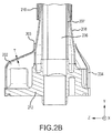
Figure 2B illustrates a schematic view of an oil tube fitting heat shield assembly, in accordance with various embodiments; -
Figure 3A illustrates a side view of an oil tube fittings heat shield assembly, in accordance with various embodiments; and -
Figure 3B illustrates a top view of an oil tube fitting heat shield, in accordance with various embodiments. - The detailed description of exemplary embodiments herein makes reference to the accompanying drawings, which show exemplary embodiments by way of illustration. While these exemplary embodiments are described in sufficient detail to enable those skilled in the art to practice the inventions, it should be understood that other embodiments may be realized and that logical changes and adaptations in design and construction may be made in accordance with this invention and the teachings herein. Thus, the detailed description herein is presented for purposes of illustration only and not of limitation. The scope of the invention is defined by the appended claims. For example, the steps recited in any of the method or process descriptions may be executed in any order and are not necessarily limited to the order presented. Furthermore, any reference to singular includes plural embodiments, and any reference to more than one component or step may include a singular embodiment or step. Also, any reference to attached, fixed, connected or the like may include permanent, removable, temporary, partial, full and/or any other possible attachment option. Additionally, any reference to without contact (or similar phrases) may also include reduced contact or minimal contact. Surface shading lines may be used throughout the figures to denote different parts but not necessarily to denote the same or different materials. In some cases, reference coordinates may be specific to each figure.
- As used herein, "aft" refers to the direction associated with the tail (e.g., the back end) of an aircraft, or generally, to the direction of exhaust of the gas turbine. As used herein, "forward" refers to the direction associated with the nose (e.g., the front end) of an aircraft, or generally, to the direction of flight or motion.
- As used herein, "distal" refers to the direction radially outward, or generally, away from the axis of rotation of a turbine engine. As used herein, "proximal" refers to a direction radially inward, or generally, towards the axis of rotation of a turbine engine.
- In various embodiments and with reference to
FIG. 1 , agas turbine engine 20 is provided.Gas turbine engine 20 may be a two-spool turbofan that generally incorporates afan section 22, acompressor section 24, acombustor section 26 and aturbine section 28. Alternative engines may include, for example, an augmenter section among other systems or features. In operation,fan section 22 can drive air along a bypass flow-path B whilecompressor section 24 can drive air for compression and communication intocombustor section 26 then expansion throughturbine section 28. Although depicted as a turbofangas turbine engine 20 herein, it should be understood that the concepts described herein are not limited to use with turbofans as the teachings may be applied to other types of gas turbine engines including three-spool architectures. -
Gas turbine engine 20 may generally comprise alow speed spool 30 and ahigh speed spool 32 mounted for rotation about an engine central longitudinal axis A-A' relative to an enginestatic structure 36 via one or more bearing systems 38 (shown as bearing system 38-1 and bearing system 38-2). It should be understood thatvarious bearing systems 38 at various locations may alternatively or additionally be provided, including for example,bearing system 38, bearing system 38-1, and bearing system 38-2. -
Low speed spool 30 may generally comprise aninner shaft 40 that interconnects afan 42, a low pressure (or first) compressor section 44 (also referred to a low pressure compressor) and a low pressure (or first)turbine section 46.Inner shaft 40 may be connected tofan 42 through a gearedarchitecture 48 that can drivefan 42 at a lower speed thanlow speed spool 30.Geared architecture 48 may comprise a gear assembly 60 enclosed within agear housing 62. Gear assembly 60 couplesinner shaft 40 to a rotating fan structure.High speed spool 32 may comprise anouter shaft 50 that interconnects a high pressure compressor 52 (e.g., a second compressor section) and high pressure (or second) turbine section ("HPT") 54. Acombustor 56 may be located betweenhigh pressure compressor 52 andHPT 54. Amid-turbine frame 57 of enginestatic structure 36 may be located generally betweenHPT 54 andlow pressure turbine 46.Mid-turbine frame 57 may support one ormore bearing systems 38 inturbine section 28.Inner shaft 40 andouter shaft 50 may be concentric and rotate via bearingsystems 38 about the engine central longitudinal axis A-A', which is collinear with their longitudinal axes. As used herein, a "high pressure" compressor or turbine experiences a higher pressure than a corresponding "low pressure" compressor or turbine. - The core airflow may be compressed by
low pressure compressor 44 thenhigh pressure compressor 52, mixed and burned with fuel incombustor 56, then expanded overHPT 54 andlow pressure turbine 46.Mid-turbine frame 57 includesairfoils 59 which are in the core airflow path.Low pressure turbine 46 andHPT 54 rotationally drive the respectivelow speed spool 30 andhigh speed spool 32 in response to the expansion. -
Gas turbine engine 20 may be, for example, a high-bypass geared aircraft engine. In various embodiments, the bypass ratio ofgas turbine engine 20 may be greater than about six (6). In various embodiments, the bypass ratio ofgas turbine engine 20 may be greater than ten (10). In various embodiments, gearedarchitecture 48 may be an epicyclic gear train, such as a star gear system (sun gear in meshing engagement with a plurality of star gears supported by a carrier and in meshing engagement with a ring gear) or other gear system.Geared architecture 48 may have a gear reduction ratio of greater than about 2.3 andlow pressure turbine 46 may have a pressure ratio that is greater than about 5. In various embodiments, the bypass ratio ofgas turbine engine 20 is greater than about ten (10:1). In various embodiments, the diameter offan 42 may be significantly larger than that of thelow pressure compressor 44, and thelow pressure turbine 46 may have a pressure ratio that is greater than about (5:1).Low pressure turbine 46 pressure ratio may be measured prior to inlet oflow pressure turbine 46 as related to the pressure at the outlet oflow pressure turbine 46 prior to an exhaust nozzle. It should be understood, however, that the above parameters are exemplary of various embodiments of a suitable geared architecture engine and that the present disclosure contemplates other gas turbine engines including direct drive turbofans. - In various embodiments, with reference to
FIG. 2A , a mid-turbine frame (MTF) assembly is illustrated.MTF assembly 257 may include bearingcompartment 238,outer case 266, andinner case 268.MTF vane 259 may be located betweeninner case 268 andouter case 266. Oil tube fitting 212 may be attached to a portion ofbearing compartment 238.Oil tube 206 may extend betweenouter case 266 and oil tube fitting 212.Oil 214 may be located withinoil tube 206.Oil 214 may be used to lubricate at least a portion ofbearing compartment 238.Oil tube 206 may be located at least partially withinMTF vane 259.Sleeve 210 may encase at least a portion ofoil tube 206. Oil tube fitting heat shield (also referred to herein as heat shield) 202 may be located betweenMTF vane 259 and oil tube fitting 212. - Extremely hot exhaust may impinge on
MTF vane 259 which may causeMTF vane 259 to increase in temperature due to convective heat transfer from the hot exhaust. Heat waves 218 may radiate fromMTF vane 259. In various embodiments, heat waves may radiate to other nearby components which may cause the nearby components to increase in temperature. In return, the nearby components may transfer heat conductively to other adjacent components and/or fluids. For example, heat waves may radiate fromMTF vane 259 tooil tube 206 which may convectively transfer heat fromMTF vane 259 tooil tube 206. Heat may be conductively transferred to oil located insideoil tube 206. Furthermore, when oil exceeds various threshold temperatures, it may undergo severe oxidative and thermal breakdown which may cause solid deposits to form. These deposits may be undesirable as they may impede the flow of fluid through various components including, for example, tubes and filters.Heat shield 202 may be configured to blockheat waves 218 radiating fromMTF vane 259 from directly impinging on oil tube fitting 212. Furthermore,heat shield 202 may help minimize convective heat transfer from hot air surrounding oil tube fitting 212. Accordingly,heat shield 202 may help block heat from being transferred to oil tube fitting 212. In various embodiments,heat shield 202 may help prevent oil from coking within oil tube fitting 212.Sleeve 210 may be configured to block radiating heat waves fromMTF vane 259 from impinging onoil tube 206. - In various embodiments, with reference to
FIG. 2B ,oil tube 206 may comprise aninner tube 207 and anouter tube 208. Accordingly,oil tube 206 may be referred to as a dual wall tube.Inner tube 207 may be enclosed byouter tube 208. There may be a space betweeninner tube 207 andouter tube 208 which may be occupied by air. Theouter tube 208 may be configured to contain oil withinouter tube 208 in the event that there is an oil leak frominner tube 207.Outer tube 208 may be configured to prevent heat transfer from surrounding hot air toinner tube 207.Oil tube 206 may be configured to attach to oil tube fitting 212.Oil tube 206 may be attached to oil tube fitting 212 via weld, solder, braze, or any other suitable method.Heat shield 202 may comprise abase portion 204 and atop portion 203.Top portion 203 ofheat shield 202 may be configured to attach tooil tube 206.Top portion 203 ofheat shield 202 may be configured to attach tooil tube 206 via weld, solder, braze, or any other suitable method.Top portion 203 ofheat shield 202 may be configured to attach tooil tube 206 in close proximity to an end ofoil tube 206.Top portion 203 ofheat shield 202 may be configured to attach tooil tube 206 in close proximity to a proximal end ofoil tube 206.Top portion 203 ofheat shield 202 may be configured to attach tooil tube 206 such that there is a small gap betweenheat shield 202 andsleeve 210.Base portion 204 ofheat shield 202 may be configured to at least partially encase oil tube fitting 212. - In various embodiments, various components of MTF assemblies may comprise various materials. Various components, including
heat shield 202, may comprise a high temperature metal (e.g., an austenitic nickel-chromium-based alloy such as INCONEL), a high temperature composite, and/or the like. In further embodiments,heat shield 202 may comprise a high temperature stainless steel. - In various embodiments,
heat shield 202 may comprise a wall thickness "T." In various embodiments,heat shield 202 may be manufactured via a hydro-forming process. Wall thickness "T" may be chosen according to various design considerations. In various embodiments, wall thickness "T" may be between 0.010 in (0.25 mm) and 0.030 in (0.76 mm) in thick. During manufacturing, sheet metal of a preferred wall thickness may be chosen to be hydro-formed to the desired heat shield geometry. For example, if a heat shield comprising a wall thickness of 0.5 mm is desired, a piece of sheet metal comprising a wall thickness of 0.5 mm may be used and formed into the desired geometry using high pressure hydraulic fluid to press the sheet metal into a die in a process known as hydro-forming. In various embodiments, a single piece of sheet metal may be hydro-formed intoheat shield 202. In various embodiments, two or more pieces of sheet metal may be hydro-formed into different geometries and welded together to formheat shield 202. - With reference to
FIG 3A and FIG 3B , elements with like element numbering as depicted inFIG 2A andFIG 2B , are intended to be the same and certain properties, including material properties, will not be repeated for the sake of clarity. - In various embodiments, with reference to
FIG 3A and FIG 3B , oil tube fitting 312 may be separated fromheat shield 302 by a gap "G".Heat shield 302 may be configured to be separated from oil tube fitting 312 by gap "G" such that a conductive thermal path does not exist betweenheat shield 302 and oil tube fitting 312. Gap "G" may be configured to be minimal while allowing thermal expansion ofheat shield 302 and oil tube fitting 312 without creating a thermal conduction path betweenheat shield 302 and oil tube fitting 312. Minimizing gap "G" may allowheat shield 302 to more effectively minimize convective heat transfer between oil tube fitting 312 and surrounding hot air. Minimizing gap "G" may allowheat shield 302 to more effectively minimize convective heat transfer between oil tube fitting 312 and radiated heat from an adjacent MTF vane. - In various embodiments, the
base portion 304 ofheat shield 302 may comprise a triangular geometry. For example,FIG 3B illustrates thebase portion 304 ofheat shield 302, wherein the base portion bounds a triangular void. In various embodiments, thebase portion 304 ofheat shield 302 may comprise one of a square, rectangular, oblong, round, elliptical, or any other geometry. The geometry of thebase portion 304 ofheat shield 302 may be driven by the geometry of oil tube fitting 312. Accordingly, the geometry of oil tube fitting 312 andbase portion 304 may be complementary. In various embodiments, thetop portion 303 ofheat shield 302 may comprise an ovular geometry. For example,FIG 3B illustrates thetop portion 303 ofheat shield 302, wherein thetop portion 303 bounds an ovular void. In various embodiments, thetop portion 303 ofheat shield 302 may comprise a square, rectangular, oblong, round, elliptical, or any other geometry. The geometry of thetop portion 303 ofheat shield 302 may be driven by the geometry ofoil tube 306. Accordingly, the geometry ofoil tube 306 andtop portion 303 may be complementary. In various embodiments, the geometry oftop portion 303 andbase portion 304 may be complementary. In various embodiments, the geometry oftop portion 303 andbase portion 304 may be different. In various embodiments,top portion 303 may be connected tobase portion 304 by a taperedportion 305. - In various embodiments,
top portion 303 may comprise a cross-sectional area. The cross-sectional area oftop portion 303 may be the area of a slice oftop portion 303 taken along line B-B in the x-z plane according to the coordinates provided inFIG 3A . The cross-sectional area oftop portion 303 may be best visualized by viewingtop portion 303 from the top view as shown inFIG 3B . In various embodiments,base portion 304 may comprise a cross-sectional area. The cross-sectional area ofbase portion 304 may be the area of a slice ofbase portion 304 taken along line C-C in the x-z plane according to the coordinates provided inFIG 3A . The cross-sectional area ofbase portion 304 may be best visualized by viewingbase portion 304 from the top view as shown inFIG 3B . - A method of cooling an oil tube fitting is disclosed herein, in accordance with various embodiments. The method of cooling an oil tube fitting may include disposing a heat shield about an oil tube. When in the installed position, the heat shield may at least partially encase an oil tube fitting. When in the installed position and during operation, the heat shield may be configured to prevent heat transfer between the oil tube fitting and surrounding hot air. When in the installed position, the heat shield may be configured to be separated from the oil tube fitting by a gap.
- Benefits, other advantages, and solutions to problems have been described herein with regard to specific embodiments. Furthermore, the connecting lines shown in the various figures contained herein are intended to represent exemplary functional relationships and/or physical couplings between the various elements. It should be noted that many alternative or additional functional relationships or physical connections may be present in a practical system. However, the benefits, advantages, solutions to problems, and any elements that may cause any benefit, advantage, or solution to occur or become more pronounced are not to be construed as critical, required, or essential features or elements of the inventions. The scope of the inventions is accordingly to be limited by nothing other than the appended claims, in which reference to an element in the singular is not intended to mean "one and only one" unless explicitly so stated, but rather "one or more." Moreover, where a phrase similar to "at least one of A, B, or C" is used in the claims, it is intended that the phrase be interpreted to mean that A alone may be present in an embodiment, B alone may be present in an embodiment, C alone may be present in an embodiment, or that any combination of the elements A, B and C may be present in a single embodiment; for example, A and B, A and C, B and C, or A and B and C. Systems, methods and apparatus are provided herein. In the detailed description herein, references to "one embodiment", "an embodiment", "various embodiments", etc., indicate that the embodiment described may include a particular feature, structure, or characteristic, but every embodiment may not necessarily include the particular feature, structure, or characteristic. Moreover, such phrases are not necessarily referring to the same embodiment. Further, when a particular feature, structure, or characteristic is described in connection with an embodiment, it is submitted that it is within the knowledge of one skilled in the art to affect such feature, structure, or characteristic in connection with other embodiments whether or not explicitly described. After reading the description, it will be apparent to one skilled in the relevant art(s) how to implement the disclosure in alternative embodiments.
Claims (13)
- A heat shield (202, 302) comprising:a base portion (204; 304), wherein the base portion (204; 304) bounds a triangular void;a top portion (203; 303), wherein the top portion (203; 303) bounds an ovular void; anda tapered portion (305), wherein the tapered portion (305) extends between the base portion (204; 304) and the top portion (203; 303), the top portion (203; 303) having a smaller cross-sectional area than the base portion (204; 304).
- The heat shield of claim 1, wherein the heat shield (202; 302) is configured to at least partially encase a fitting (212; 312).
- The heat shield of claim 2, wherein the heat shield (202; 302) is configured to impede heat transfer between the fitting (212; 312) and surrounding air.
- The lubricating assembly of claim 2, wherein the heat shield is configured to prevent heat transfer between the fitting and surrounding air.
- The heat shield of claim 2, 3 or 4, wherein the heat shield (202; 302) and the fitting (212; 312) are separated by a gap (G).
- The heat shield of any preceding claim, wherein the top portion (203; 303) is configured to be attached to a tube (206; 306).
- The heat shield of any preceding claim, wherein the heat shield (202; 302) is manufactured via a hydro-forming process.
- The heat shield of any preceding claim, wherein the heat shield (202; 302) comprises at least one of a nickel-chromium based alloy and a stainless steel.
- A lubricating assembly comprising:an oil tube (206; 306),a fitting (212; 312), wherein the fitting (212; 312) is configured to be attached to the oil tube (206; 306); andthe heat shield (202; 302) of any preceding claim.
- The lubricating assembly of claim 9, wherein the oil tube (206; 306) is a dual wall oil tube comprising an inner wall and an outer wall.
- A method of cooling an oil tube fitting (212; 312) comprising:hydro-forming a heat shield (202; 302);coupling the heat shield (202; 302) to an outer surface of an oil tube (206; 306); andcoupling the oil tube (206; 306) to the oil tube fitting (212; 312), wherein the heat shield (202; 302) at least partially encases the oil tube fitting (212; 312).
- The method of cooling an oil tube fitting of claim 11, further comprising reflecting, by the heat shield (202; 302), a heat wave away from the oil tube fitting (212; 312).
- The method of cooling an oil tube fitting of claim 11 or 12, wherein the heat shield (202; 302) is configured to be separated from the oil tube fitting (212; 312) by a gap (G).
Applications Claiming Priority (1)
| Application Number | Priority Date | Filing Date | Title |
|---|---|---|---|
| US14/682,767 US10443440B2 (en) | 2015-04-09 | 2015-04-09 | Heat shield, systems and methods |
Publications (2)
| Publication Number | Publication Date |
|---|---|
| EP3081760A1 true EP3081760A1 (en) | 2016-10-19 |
| EP3081760B1 EP3081760B1 (en) | 2019-11-13 |
Family
ID=55806142
Family Applications (1)
| Application Number | Title | Priority Date | Filing Date |
|---|---|---|---|
| EP16164697.1A Active EP3081760B1 (en) | 2015-04-09 | 2016-04-11 | Lubricating assembly comprising a heat shield, systems and methods |
Country Status (2)
| Country | Link |
|---|---|
| US (2) | US10443440B2 (en) |
| EP (1) | EP3081760B1 (en) |
Cited By (11)
| Publication number | Priority date | Publication date | Assignee | Title |
|---|---|---|---|---|
| EP3318729A1 (en) * | 2016-11-04 | 2018-05-09 | United Technologies Corporation | Apparatus and method for providing fluid to a bearing damper |
| EP3358139A1 (en) * | 2017-02-06 | 2018-08-08 | United Technologies Corporation | Threaded fitting for tube |
| EP3348801A3 (en) * | 2016-11-04 | 2018-12-12 | United Technologies Corporation | Apparatus and method for providing fluid to a bearing damper |
| EP3470630A1 (en) * | 2017-10-13 | 2019-04-17 | United Technologies Corporation | Double wall service tube with annular airflow passage |
| US10385710B2 (en) | 2017-02-06 | 2019-08-20 | United Technologies Corporation | Multiwall tube and fitting for bearing oil supply |
| US10465828B2 (en) | 2017-02-06 | 2019-11-05 | United Technologies Corporation | Tube fitting |
| US10830139B2 (en) | 2017-02-06 | 2020-11-10 | Raytheon Technologies Corporation | Fitting for multiwall tube |
| EP3798418A1 (en) * | 2019-09-17 | 2021-03-31 | Rolls-Royce plc | A weaved composite gas turbine vane and method |
| US11413831B2 (en) | 2019-09-17 | 2022-08-16 | Rolls-Royce Plc | Tool for compacting a composite preform assembly and a method for the same |
| FR3142502A1 (en) * | 2022-11-24 | 2024-05-31 | Safran Aircraft Engines | CASING INCLUDING A REINFORCED SEALING SERVICE FOR LUBRICATING THE BEARING SUPPORT OF A TURBOMACHINE CASING |
| US12084987B2 (en) | 2019-09-17 | 2024-09-10 | Rolls-Royce Plc | Stator vane ring and a method of manufacture |
Families Citing this family (8)
| Publication number | Priority date | Publication date | Assignee | Title |
|---|---|---|---|---|
| US10443449B2 (en) | 2015-07-24 | 2019-10-15 | Pratt & Whitney Canada Corp. | Spoke mounting arrangement |
| CA2936180C (en) | 2015-07-24 | 2025-05-06 | Pratt & Whitney Canada Corp. | Multiple spoke cooling system and method |
| US10247035B2 (en) | 2015-07-24 | 2019-04-02 | Pratt & Whitney Canada Corp. | Spoke locking architecture |
| US10727656B2 (en) * | 2017-11-08 | 2020-07-28 | Raytheon Technologies Corporation | Igniter cable conduit for gas turbine engine |
| US11230995B2 (en) | 2017-11-08 | 2022-01-25 | Raytheon Technologies Corporation | Cable conduit for turbine engine bypass |
| US11230944B2 (en) * | 2019-11-22 | 2022-01-25 | Raytheon Technologies Corporation | Heat shield for gas turbine fluid tubes |
| US11085313B2 (en) * | 2019-11-22 | 2021-08-10 | Raytheon Technologies Corporation | System and method for transporting lubricant through a vane |
| US12601280B2 (en) | 2024-08-29 | 2026-04-14 | Pratt & Whitney Canada Corp. | Boss with integral fire protection |
Citations (4)
| Publication number | Priority date | Publication date | Assignee | Title |
|---|---|---|---|---|
| US20050199445A1 (en) * | 2004-03-09 | 2005-09-15 | Honeywell International Inc. | Apparatus and method for bearing lubrication in turbine engines |
| US20110085895A1 (en) * | 2009-10-09 | 2011-04-14 | Pratt & Whitney Canada Corp. | Oil tube with integrated heat shield |
| WO2014105573A1 (en) * | 2012-12-29 | 2014-07-03 | United Technologies Corporation | Heat shield based air dam for a turbine exhaust case |
| WO2014105602A1 (en) * | 2012-12-29 | 2014-07-03 | United Technologies Corporation | Heat shield for a casing |
Family Cites Families (19)
| Publication number | Priority date | Publication date | Assignee | Title |
|---|---|---|---|---|
| JPS51116323A (en) * | 1975-04-04 | 1976-10-13 | Nissan Motor Co Ltd | Heat shading device of exhaust system |
| US4612767A (en) * | 1985-03-01 | 1986-09-23 | Caterpillar Inc. | Exhaust manifold shield |
| US5598696A (en) * | 1994-09-20 | 1997-02-04 | Parker-Hannifin Corporation | Clip attached heat shield |
| US6598389B2 (en) * | 2001-06-12 | 2003-07-29 | Dana Corporation | Insulated heat shield |
| JP3940053B2 (en) * | 2002-09-30 | 2007-07-04 | 本田技研工業株式会社 | Heat shield device for exhaust system of internal combustion engine |
| US6854487B2 (en) * | 2003-06-26 | 2005-02-15 | General Electric Company | Fluid conduit wall inhibiting heat transfer and method for making |
| US20050019944A1 (en) * | 2003-07-23 | 2005-01-27 | Eastman Kodak Company | Colorable microspheres for DNA and protein microarray |
| US7481248B2 (en) * | 2004-09-15 | 2009-01-27 | Pratt & Whitney Canada Corp. | Flexible heat shields and method |
| DE102005006319A1 (en) * | 2005-02-11 | 2006-08-24 | Elringklinger Ag | Shielding part, in particular heat shield |
| DE102005006320A1 (en) * | 2005-02-11 | 2006-08-24 | Elringklinger Ag | Shielding part, in particular heat shield |
| US7823643B2 (en) * | 2006-06-05 | 2010-11-02 | Fmc Technologies Inc. | Insulation shroud with internal support structure |
| US7775047B2 (en) * | 2006-09-22 | 2010-08-17 | Pratt & Whitney Canada Corp. | Heat shield with stress relieving feature |
| US7926286B2 (en) * | 2006-09-26 | 2011-04-19 | Pratt & Whitney Canada Corp. | Heat shield for a fuel manifold |
| US8151870B2 (en) * | 2006-11-14 | 2012-04-10 | The Southern Company | Tube shield assembly and method of securing same |
| DE102009005013B4 (en) * | 2009-01-17 | 2019-12-12 | Ihi Charging Systems International Gmbh | Connecting arrangement of a turbine housing with a bearing housing and exhaust gas turbocharger |
| US8459941B2 (en) * | 2009-06-15 | 2013-06-11 | General Electric Company | Mechanical joint for a gas turbine engine |
| US8844643B2 (en) * | 2011-03-08 | 2014-09-30 | Honeywell International Inc. | Fireproof systems with local heat shields for aircraft engines |
| US8944749B2 (en) * | 2012-01-24 | 2015-02-03 | Pratt & Whitney Canada Corp. | Oil purge system for a mid turbine frame |
| US20180051618A1 (en) * | 2016-08-18 | 2018-02-22 | GM Global Technology Operations LLC | Geometrically optimized gas sensor heat shield |
-
2015
- 2015-04-09 US US14/682,767 patent/US10443440B2/en active Active
-
2016
- 2016-04-11 EP EP16164697.1A patent/EP3081760B1/en active Active
-
2019
- 2019-05-14 US US16/412,187 patent/US11028729B2/en active Active
Patent Citations (4)
| Publication number | Priority date | Publication date | Assignee | Title |
|---|---|---|---|---|
| US20050199445A1 (en) * | 2004-03-09 | 2005-09-15 | Honeywell International Inc. | Apparatus and method for bearing lubrication in turbine engines |
| US20110085895A1 (en) * | 2009-10-09 | 2011-04-14 | Pratt & Whitney Canada Corp. | Oil tube with integrated heat shield |
| WO2014105573A1 (en) * | 2012-12-29 | 2014-07-03 | United Technologies Corporation | Heat shield based air dam for a turbine exhaust case |
| WO2014105602A1 (en) * | 2012-12-29 | 2014-07-03 | United Technologies Corporation | Heat shield for a casing |
Cited By (13)
| Publication number | Priority date | Publication date | Assignee | Title |
|---|---|---|---|---|
| EP3348801A3 (en) * | 2016-11-04 | 2018-12-12 | United Technologies Corporation | Apparatus and method for providing fluid to a bearing damper |
| EP3318729A1 (en) * | 2016-11-04 | 2018-05-09 | United Technologies Corporation | Apparatus and method for providing fluid to a bearing damper |
| US10830139B2 (en) | 2017-02-06 | 2020-11-10 | Raytheon Technologies Corporation | Fitting for multiwall tube |
| EP3358139A1 (en) * | 2017-02-06 | 2018-08-08 | United Technologies Corporation | Threaded fitting for tube |
| US10385710B2 (en) | 2017-02-06 | 2019-08-20 | United Technologies Corporation | Multiwall tube and fitting for bearing oil supply |
| US10393303B2 (en) | 2017-02-06 | 2019-08-27 | United Technologies Corporation | Threaded fitting for tube |
| US10465828B2 (en) | 2017-02-06 | 2019-11-05 | United Technologies Corporation | Tube fitting |
| EP3470630A1 (en) * | 2017-10-13 | 2019-04-17 | United Technologies Corporation | Double wall service tube with annular airflow passage |
| EP3798418A1 (en) * | 2019-09-17 | 2021-03-31 | Rolls-Royce plc | A weaved composite gas turbine vane and method |
| US11415008B2 (en) | 2019-09-17 | 2022-08-16 | Rolls-Royce Plc | Vane |
| US11413831B2 (en) | 2019-09-17 | 2022-08-16 | Rolls-Royce Plc | Tool for compacting a composite preform assembly and a method for the same |
| US12084987B2 (en) | 2019-09-17 | 2024-09-10 | Rolls-Royce Plc | Stator vane ring and a method of manufacture |
| FR3142502A1 (en) * | 2022-11-24 | 2024-05-31 | Safran Aircraft Engines | CASING INCLUDING A REINFORCED SEALING SERVICE FOR LUBRICATING THE BEARING SUPPORT OF A TURBOMACHINE CASING |
Also Published As
| Publication number | Publication date |
|---|---|
| EP3081760B1 (en) | 2019-11-13 |
| US20160326910A1 (en) | 2016-11-10 |
| US10443440B2 (en) | 2019-10-15 |
| US11028729B2 (en) | 2021-06-08 |
| US20190277160A1 (en) | 2019-09-12 |
Similar Documents
| Publication | Publication Date | Title |
|---|---|---|
| US11028729B2 (en) | Heat shield, systems and methods | |
| US10494963B2 (en) | Thermally compliant heatshield | |
| EP3730743B1 (en) | Multiwall tube and fitting for bearing oil supply | |
| EP3358139B1 (en) | Threaded fitting for tube | |
| EP3064716B1 (en) | Mid turbine frame with integrated inner case heat shield | |
| EP3358140B1 (en) | Fitting for multiwall tube | |
| EP3252352A1 (en) | 2 ply w seal using dissimilar materials | |
| EP2888463B1 (en) | Annular turbomachine seal and heat shield | |
| EP3048250B1 (en) | Overcooled air cooling system with annular mixing passage | |
| EP3109405B1 (en) | A cooled vane for use in a gas turbine engine comprising baffles with reduced pressure loss | |
| EP3232018B1 (en) | Heat shield with axial retention lock | |
| EP4290056A1 (en) | Turbine engine shaft plug | |
| EP3354851A1 (en) | Hybrid airfoil cooling | |
| EP3081762B1 (en) | Static axial brush seal with dual bristle packs | |
| EP3232019A1 (en) | Heat shield with axial retention lock | |
| EP3102808B1 (en) | Gas turbine engine with cooling fluid composite tube | |
| EP3189922B1 (en) | Advanced braze joint for tube-to-tube connection | |
| EP2910735B1 (en) | Bore basket for a gas powered turbine | |
| EP3279448B1 (en) | Annular heatshield in a gas turbine fan section | |
| EP3081761A1 (en) | Mid-turbine frame and gas turbine with a mid-turbine frame | |
| EP3623575A1 (en) | Serpentine turn cover for gas turbine stator vane assembly | |
| EP3249176B1 (en) | Dirt shield | |
| US9926789B2 (en) | Flow splitting baffle |
Legal Events
| Date | Code | Title | Description |
|---|---|---|---|
| PUAI | Public reference made under article 153(3) epc to a published international application that has entered the european phase |
Free format text: ORIGINAL CODE: 0009012 |
|
| AK | Designated contracting states |
Kind code of ref document: A1 Designated state(s): AL AT BE BG CH CY CZ DE DK EE ES FI FR GB GR HR HU IE IS IT LI LT LU LV MC MK MT NL NO PL PT RO RS SE SI SK SM TR |
|
| AX | Request for extension of the european patent |
Extension state: BA ME |
|
| RAP1 | Party data changed (applicant data changed or rights of an application transferred) |
Owner name: UNITED TECHNOLOGIES CORPORATION |
|
| STAA | Information on the status of an ep patent application or granted ep patent |
Free format text: STATUS: REQUEST FOR EXAMINATION WAS MADE |
|
| 17P | Request for examination filed |
Effective date: 20170419 |
|
| RBV | Designated contracting states (corrected) |
Designated state(s): AL AT BE BG CH CY CZ DE DK EE ES FI FR GB GR HR HU IE IS IT LI LT LU LV MC MK MT NL NO PL PT RO RS SE SI SK SM TR |
|
| STAA | Information on the status of an ep patent application or granted ep patent |
Free format text: STATUS: EXAMINATION IS IN PROGRESS |
|
| 17Q | First examination report despatched |
Effective date: 20180919 |
|
| GRAP | Despatch of communication of intention to grant a patent |
Free format text: ORIGINAL CODE: EPIDOSNIGR1 |
|
| STAA | Information on the status of an ep patent application or granted ep patent |
Free format text: STATUS: GRANT OF PATENT IS INTENDED |
|
| INTG | Intention to grant announced |
Effective date: 20190531 |
|
| GRAS | Grant fee paid |
Free format text: ORIGINAL CODE: EPIDOSNIGR3 |
|
| GRAA | (expected) grant |
Free format text: ORIGINAL CODE: 0009210 |
|
| STAA | Information on the status of an ep patent application or granted ep patent |
Free format text: STATUS: THE PATENT HAS BEEN GRANTED |
|
| AK | Designated contracting states |
Kind code of ref document: B1 Designated state(s): AL AT BE BG CH CY CZ DE DK EE ES FI FR GB GR HR HU IE IS IT LI LT LU LV MC MK MT NL NO PL PT RO RS SE SI SK SM TR |
|
| REG | Reference to a national code |
Ref country code: CH Ref legal event code: EP Ref country code: AT Ref legal event code: REF Ref document number: 1201855 Country of ref document: AT Kind code of ref document: T Effective date: 20191115 |
|
| REG | Reference to a national code |
Ref country code: DE Ref legal event code: R096 Ref document number: 602016024132 Country of ref document: DE |
|
| REG | Reference to a national code |
Ref country code: IE Ref legal event code: FG4D |
|
| REG | Reference to a national code |
Ref country code: NL Ref legal event code: MP Effective date: 20191113 |
|
| REG | Reference to a national code |
Ref country code: LT Ref legal event code: MG4D |
|
| PG25 | Lapsed in a contracting state [announced via postgrant information from national office to epo] |
Ref country code: FI Free format text: LAPSE BECAUSE OF FAILURE TO SUBMIT A TRANSLATION OF THE DESCRIPTION OR TO PAY THE FEE WITHIN THE PRESCRIBED TIME-LIMIT Effective date: 20191113 Ref country code: GR Free format text: LAPSE BECAUSE OF FAILURE TO SUBMIT A TRANSLATION OF THE DESCRIPTION OR TO PAY THE FEE WITHIN THE PRESCRIBED TIME-LIMIT Effective date: 20200214 Ref country code: NO Free format text: LAPSE BECAUSE OF FAILURE TO SUBMIT A TRANSLATION OF THE DESCRIPTION OR TO PAY THE FEE WITHIN THE PRESCRIBED TIME-LIMIT Effective date: 20200213 Ref country code: PL Free format text: LAPSE BECAUSE OF FAILURE TO SUBMIT A TRANSLATION OF THE DESCRIPTION OR TO PAY THE FEE WITHIN THE PRESCRIBED TIME-LIMIT Effective date: 20191113 Ref country code: SE Free format text: LAPSE BECAUSE OF FAILURE TO SUBMIT A TRANSLATION OF THE DESCRIPTION OR TO PAY THE FEE WITHIN THE PRESCRIBED TIME-LIMIT Effective date: 20191113 Ref country code: LV Free format text: LAPSE BECAUSE OF FAILURE TO SUBMIT A TRANSLATION OF THE DESCRIPTION OR TO PAY THE FEE WITHIN THE PRESCRIBED TIME-LIMIT Effective date: 20191113 Ref country code: BG Free format text: LAPSE BECAUSE OF FAILURE TO SUBMIT A TRANSLATION OF THE DESCRIPTION OR TO PAY THE FEE WITHIN THE PRESCRIBED TIME-LIMIT Effective date: 20200213 Ref country code: PT Free format text: LAPSE BECAUSE OF FAILURE TO SUBMIT A TRANSLATION OF THE DESCRIPTION OR TO PAY THE FEE WITHIN THE PRESCRIBED TIME-LIMIT Effective date: 20200313 Ref country code: LT Free format text: LAPSE BECAUSE OF FAILURE TO SUBMIT A TRANSLATION OF THE DESCRIPTION OR TO PAY THE FEE WITHIN THE PRESCRIBED TIME-LIMIT Effective date: 20191113 Ref country code: NL Free format text: LAPSE BECAUSE OF FAILURE TO SUBMIT A TRANSLATION OF THE DESCRIPTION OR TO PAY THE FEE WITHIN THE PRESCRIBED TIME-LIMIT Effective date: 20191113 |
|
| PG25 | Lapsed in a contracting state [announced via postgrant information from national office to epo] |
Ref country code: IS Free format text: LAPSE BECAUSE OF FAILURE TO SUBMIT A TRANSLATION OF THE DESCRIPTION OR TO PAY THE FEE WITHIN THE PRESCRIBED TIME-LIMIT Effective date: 20200313 Ref country code: HR Free format text: LAPSE BECAUSE OF FAILURE TO SUBMIT A TRANSLATION OF THE DESCRIPTION OR TO PAY THE FEE WITHIN THE PRESCRIBED TIME-LIMIT Effective date: 20191113 Ref country code: RS Free format text: LAPSE BECAUSE OF FAILURE TO SUBMIT A TRANSLATION OF THE DESCRIPTION OR TO PAY THE FEE WITHIN THE PRESCRIBED TIME-LIMIT Effective date: 20191113 |
|
| PG25 | Lapsed in a contracting state [announced via postgrant information from national office to epo] |
Ref country code: AL Free format text: LAPSE BECAUSE OF FAILURE TO SUBMIT A TRANSLATION OF THE DESCRIPTION OR TO PAY THE FEE WITHIN THE PRESCRIBED TIME-LIMIT Effective date: 20191113 |
|
| PG25 | Lapsed in a contracting state [announced via postgrant information from national office to epo] |
Ref country code: DK Free format text: LAPSE BECAUSE OF FAILURE TO SUBMIT A TRANSLATION OF THE DESCRIPTION OR TO PAY THE FEE WITHIN THE PRESCRIBED TIME-LIMIT Effective date: 20191113 Ref country code: ES Free format text: LAPSE BECAUSE OF FAILURE TO SUBMIT A TRANSLATION OF THE DESCRIPTION OR TO PAY THE FEE WITHIN THE PRESCRIBED TIME-LIMIT Effective date: 20191113 Ref country code: EE Free format text: LAPSE BECAUSE OF FAILURE TO SUBMIT A TRANSLATION OF THE DESCRIPTION OR TO PAY THE FEE WITHIN THE PRESCRIBED TIME-LIMIT Effective date: 20191113 Ref country code: CZ Free format text: LAPSE BECAUSE OF FAILURE TO SUBMIT A TRANSLATION OF THE DESCRIPTION OR TO PAY THE FEE WITHIN THE PRESCRIBED TIME-LIMIT Effective date: 20191113 Ref country code: RO Free format text: LAPSE BECAUSE OF FAILURE TO SUBMIT A TRANSLATION OF THE DESCRIPTION OR TO PAY THE FEE WITHIN THE PRESCRIBED TIME-LIMIT Effective date: 20191113 |
|
| REG | Reference to a national code |
Ref country code: DE Ref legal event code: R097 Ref document number: 602016024132 Country of ref document: DE |
|
| REG | Reference to a national code |
Ref country code: AT Ref legal event code: MK05 Ref document number: 1201855 Country of ref document: AT Kind code of ref document: T Effective date: 20191113 |
|
| PG25 | Lapsed in a contracting state [announced via postgrant information from national office to epo] |
Ref country code: SM Free format text: LAPSE BECAUSE OF FAILURE TO SUBMIT A TRANSLATION OF THE DESCRIPTION OR TO PAY THE FEE WITHIN THE PRESCRIBED TIME-LIMIT Effective date: 20191113 Ref country code: SK Free format text: LAPSE BECAUSE OF FAILURE TO SUBMIT A TRANSLATION OF THE DESCRIPTION OR TO PAY THE FEE WITHIN THE PRESCRIBED TIME-LIMIT Effective date: 20191113 |
|
| PLBE | No opposition filed within time limit |
Free format text: ORIGINAL CODE: 0009261 |
|
| STAA | Information on the status of an ep patent application or granted ep patent |
Free format text: STATUS: NO OPPOSITION FILED WITHIN TIME LIMIT |
|
| 26N | No opposition filed |
Effective date: 20200814 |
|
| PG25 | Lapsed in a contracting state [announced via postgrant information from national office to epo] |
Ref country code: AT Free format text: LAPSE BECAUSE OF FAILURE TO SUBMIT A TRANSLATION OF THE DESCRIPTION OR TO PAY THE FEE WITHIN THE PRESCRIBED TIME-LIMIT Effective date: 20191113 Ref country code: SI Free format text: LAPSE BECAUSE OF FAILURE TO SUBMIT A TRANSLATION OF THE DESCRIPTION OR TO PAY THE FEE WITHIN THE PRESCRIBED TIME-LIMIT Effective date: 20191113 Ref country code: MC Free format text: LAPSE BECAUSE OF FAILURE TO SUBMIT A TRANSLATION OF THE DESCRIPTION OR TO PAY THE FEE WITHIN THE PRESCRIBED TIME-LIMIT Effective date: 20191113 |
|
| REG | Reference to a national code |
Ref country code: CH Ref legal event code: PL |
|
| PG25 | Lapsed in a contracting state [announced via postgrant information from national office to epo] |
Ref country code: IT Free format text: LAPSE BECAUSE OF FAILURE TO SUBMIT A TRANSLATION OF THE DESCRIPTION OR TO PAY THE FEE WITHIN THE PRESCRIBED TIME-LIMIT Effective date: 20191113 Ref country code: LU Free format text: LAPSE BECAUSE OF NON-PAYMENT OF DUE FEES Effective date: 20200411 Ref country code: CH Free format text: LAPSE BECAUSE OF NON-PAYMENT OF DUE FEES Effective date: 20200430 Ref country code: LI Free format text: LAPSE BECAUSE OF NON-PAYMENT OF DUE FEES Effective date: 20200430 |
|
| REG | Reference to a national code |
Ref country code: BE Ref legal event code: MM Effective date: 20200430 |
|
| PG25 | Lapsed in a contracting state [announced via postgrant information from national office to epo] |
Ref country code: BE Free format text: LAPSE BECAUSE OF NON-PAYMENT OF DUE FEES Effective date: 20200430 |
|
| PG25 | Lapsed in a contracting state [announced via postgrant information from national office to epo] |
Ref country code: IE Free format text: LAPSE BECAUSE OF NON-PAYMENT OF DUE FEES Effective date: 20200411 |
|
| PG25 | Lapsed in a contracting state [announced via postgrant information from national office to epo] |
Ref country code: TR Free format text: LAPSE BECAUSE OF FAILURE TO SUBMIT A TRANSLATION OF THE DESCRIPTION OR TO PAY THE FEE WITHIN THE PRESCRIBED TIME-LIMIT Effective date: 20191113 Ref country code: MT Free format text: LAPSE BECAUSE OF FAILURE TO SUBMIT A TRANSLATION OF THE DESCRIPTION OR TO PAY THE FEE WITHIN THE PRESCRIBED TIME-LIMIT Effective date: 20191113 Ref country code: CY Free format text: LAPSE BECAUSE OF FAILURE TO SUBMIT A TRANSLATION OF THE DESCRIPTION OR TO PAY THE FEE WITHIN THE PRESCRIBED TIME-LIMIT Effective date: 20191113 |
|
| PG25 | Lapsed in a contracting state [announced via postgrant information from national office to epo] |
Ref country code: MK Free format text: LAPSE BECAUSE OF FAILURE TO SUBMIT A TRANSLATION OF THE DESCRIPTION OR TO PAY THE FEE WITHIN THE PRESCRIBED TIME-LIMIT Effective date: 20191113 |
|
| REG | Reference to a national code |
Ref country code: DE Ref legal event code: R081 Ref document number: 602016024132 Country of ref document: DE Owner name: RAYTHEON TECHNOLOGIES CORPORATION (N.D.GES.D.S, US Free format text: FORMER OWNER: UNITED TECHNOLOGIES CORPORATION, FARMINGTON, CONN., US Ref country code: DE Ref legal event code: R081 Ref document number: 602016024132 Country of ref document: DE Owner name: RTX CORPORATION (N.D.GES.D. STAATES DELAWARE),, US Free format text: FORMER OWNER: UNITED TECHNOLOGIES CORPORATION, FARMINGTON, CONN., US |
|
| P01 | Opt-out of the competence of the unified patent court (upc) registered |
Effective date: 20230520 |
|
| PGFP | Annual fee paid to national office [announced via postgrant information from national office to epo] |
Ref country code: DE Payment date: 20250319 Year of fee payment: 10 |
|
| REG | Reference to a national code |
Ref country code: DE Ref legal event code: R081 Ref document number: 602016024132 Country of ref document: DE Owner name: RTX CORPORATION (N.D.GES.D. STAATES DELAWARE),, US Free format text: FORMER OWNER: RAYTHEON TECHNOLOGIES CORPORATION (N.D.GES.D.STAATES DELAWARE), ARLINGTON, VA, US |
|
| PGFP | Annual fee paid to national office [announced via postgrant information from national office to epo] |
Ref country code: GB Payment date: 20260319 Year of fee payment: 11 |
|
| PGFP | Annual fee paid to national office [announced via postgrant information from national office to epo] |
Ref country code: FR Payment date: 20260320 Year of fee payment: 11 |