EP3081731A1 - Vehcile exit assist system for optimizing exit from the vehicle during parking - Google Patents
Vehcile exit assist system for optimizing exit from the vehicle during parking Download PDFInfo
- Publication number
- EP3081731A1 EP3081731A1 EP15163629.7A EP15163629A EP3081731A1 EP 3081731 A1 EP3081731 A1 EP 3081731A1 EP 15163629 A EP15163629 A EP 15163629A EP 3081731 A1 EP3081731 A1 EP 3081731A1
- Authority
- EP
- European Patent Office
- Prior art keywords
- vehicle
- door
- vehicle door
- passenger
- driver
- Prior art date
- Legal status (The legal status is an assumption and is not a legal conclusion. Google has not performed a legal analysis and makes no representation as to the accuracy of the status listed.)
- Granted
Links
Images




Classifications
-
- B—PERFORMING OPERATIONS; TRANSPORTING
- B62—LAND VEHICLES FOR TRAVELLING OTHERWISE THAN ON RAILS
- B62D—MOTOR VEHICLES; TRAILERS
- B62D15/00—Steering not otherwise provided for
- B62D15/02—Steering position indicators ; Steering position determination; Steering aids
- B62D15/027—Parking aids, e.g. instruction means
- B62D15/0285—Parking performed automatically
Definitions
- the present invention relates generally to a vehicle exit assist system for optimizing exit from the vehicle during parking.
- a driving assist system which enables the autonomous parking of a vehicle in a parking place and that uses information about the surroundings such as e.g. other parked vehicles, moving vehicles, dynamic or stationary objects, animals, other barriers or guiding means in a parking area to perform this task.
- information about the surroundings such as e.g. other parked vehicles, moving vehicles, dynamic or stationary objects, animals, other barriers or guiding means in a parking area to perform this task.
- sensors may be utilized, such as a radar, a lidar, an IR camera and/or ultrasonic sensor among others.
- a drawback with the known art is that the methods only take into consideration passengers and passenger information which are associated to certain doors for exiting the vehicle.
- a further drawback with the known art is that there is still a prevailing risk of damage to the own vehicle or to surrounding vehicles during exit from the vehicle.
- An object of the present invention is to optimize the exit from a vehicle during parking for passenger and objects which reduces the risk of damage to the vehicle.
- a method performed by a vehicle exit assist system for optimizing the exit of a driver/passengers and/or objects from the vehicle during parking, the method comprising:
- the vehicle door counter force device is a door lock for locking the door, such as a child lock whereby opening of the vehicle door is prevented.
- the vehicle door counter force device is a friction generating device which generates a resistance force opposite the direction of opening the door that may be overcome.
- the method further comprises: sensing the weight of the sensed passenger and/or objects in the vehicle,
- the minimum required vehicle door space is larger with a sensed higher weight compared to the minimum required door space with a sensed lower weight.
- the minimum required vehicle door space is pre-set.
- the door lock is activated if the sensed weight is lower than a predefined weight threshold.
- the method further comprises:
- the method further comprises:
- a vehicle exit assist system for optimizing the exit of a driver/passenger or objects from the vehicle during parking, the system is arranged to:
- the vehicle door counter force device is a door lock for locking the vehicle door, such as a child lock, whereby opening of the vehicle door is prevented.
- the vehicle doors comprise the vehicle rear door, wherein the vehicle exit assist system is further arranged to:
- a computer program comprising computer readable code means, which when run in a connected vehicle exit assist system arranged to optimize the exit from the vehicle during parking causes the connected vehicle exit assist system arranged to optimize the exit from the vehicle during parking to perform the method according to any of the above embodiments, for example as described in [0006]-[0014].
- a computer program product comprising a computer readable medium and a computer program according to the above embodiment, for example as described in [0018], wherein the computer program is stored on the computer readable medium.
- a vehicle or vessel comprising a vehicle exit assist system according to any of the previously described embodiments, for instance according to [0015]-[0017].
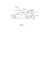
- Fig.1 shows a perspective view of a vehicle 270 comprising a vehicle exit assist system 100 for optimizing the exit of at least one driver/passenger and/or at least one object from the vehicle during parking.
- the vehicle exit assist system 100 may comprise one of e.g. the following: a IHU (Infotainment Head Unit), a TEM (Telematics Module), a CEM (Central Electronic Module) or an ECU (Electronic Control Module).
- the vehicle 270 further comprises a parking assist system 200 for assisting navigation of the vehicle 270 during parking, such as semi- or full automatic parking navigation, wherein the parking assist system 200 may comprise one of e.g.
- the vehicle 270 further comprises a vehicle door counter force device 300.
- a CEM CEM
- ECU ECU
- IHU Integrated Head Unit
- DIM Driver Information Module
- PSCM Power Steering Control Module
- the vehicle 270 further comprises a vehicle door counter force device 300.
- What is referred to as system throughout this patent application may also be known as a node.
- What is referred to as a passenger of the vehicle may also comprise the driver.
- exit may relate to the exit of persons such as driver and passengers, however also exit of objects in the sense of taking objects out of the vehicle 270.
- a procedure or method in a vehicle exit assist system 100 for optimizing the exit of at least one driver/passenger and/or at least one object from a vehicle 270 during parking will now be described with reference to Fig. 2 .
- sensing the presence of driver/passenger and/or objects in the vehicle 270 is carried out.
- the sensing is carried out by one or a plurality of sensor units 120:A-120:E, as can be seen in Fig. 5 .
- These sensor units 120:A-120:E may be arranged in or in connection with the seats and trunk of the vehicle 270 respectively.
- the sensors 120:A-120:E comprises at least one of a seat sensor, seat belt sensor, trunk sensor configured for sensing the presence and potentially the weight of driver/passengers and objects.
- the sensors 120A-120:E are pressure sensors.
- sensing the presence has the same meaning as sensing a presence or sensing for a presence, i.e. to determine whether a specific seat or trunk is occupied by a driver/passenger or object respectively.
- determination may be carried out using a determination unit based on the signals from the sensors 120:A-120E.
- the system may be initiated by a recognition of the system 100 that parking activity is initiated, e.g.
- parking activity input comprises notification that semi- or full automatic parking assist system has been initiated.
- any action that would automatically initiate the semi- or full automatic parking assist system comprises parking activities.
- the vehicle exit assist system 100 determines passenger and/or object location data in the vehicle 270 based on sensed presence in the forgoing step, i.e. if a driver/passenger and/or object is sensed, the system 100 determines the location of the driver/passenger and/or objects.
- the location is the passenger seats.
- the location comprises the trunk.
- the determined passenger and/or object location data is transmitted to a park assist system 200 for determining optimal parking route and parking position data in a parking spot. The determination of an optimal parking route and position based on the information concerning the position of the passengers is carried out by known means in known parking- or driving assist systems.
- a driving assist system which enables the autonomous parking of a vehicle in a parking place and that uses information about the surroundings such as e.g. other parked vehicles, moving vehicles, dynamic or stationary objects, animals, other barriers or guiding means in a parking area to perform this task.
- information about the surroundings such as e.g. other parked vehicles, moving vehicles, dynamic or stationary objects, animals, other barriers or guiding means in a parking area to perform this task.
- sensors may be utilized, such as a radar, a lidar, an IR camera and/or ultrasonic sensor among others. It is known in the art to provide automatic parking control systems wherein the most optimal position of the vehicle 270 in such parking spot takes into consideration the available vehicle door space for each door having an associated passenger, wherein the doors are openable for allowing an exit and calculates the position of the vehicle 270 thereafter.
- the vehicle exit assist node 100 receives the optimal parking position data from the parking assist node 200.
- the vehicle exit assist system 100 requests available vehicle door space ⁇ av for each door having an associated passenger and/or object. The request may be sent to the parking assist node 200 or within the vehicle exit assist node 100.
- the available door space ⁇ av is defined as a share of maximum door space, e.g. expressed as an angle ⁇ av , wherein a maximum opened vehicle door is 100%, i.e. not restricted by any external obstacles, is defined as ⁇ max .
- the vehicle exit assist node 100 receives available vehicle door space ⁇ av for each door having an associated passenger and/or object from e.g. the vehicle exit assist node 100 or the parking assist node 200.
- ⁇ av may be any share of ⁇ max , and depend on various parameters such as e.g. weight of the associated driver/passenger and/or object as described below.
- the vehicle exit assist node 100 activates a vehicle door counter force device 300 for creating a force against opening the vehicle door if the available vehicle door space ⁇ av is less than a minimum required vehicle door space ⁇ req i.e. if ⁇ av ⁇ req , for each vehicle door 280a, 280b, 280c, 280d, 280e, as shown in e.g. Fig. 3a, 3b , having an associated driver/passenger or object.
- the vehicle door counter force device 300 is a door lock for locking the door 280a, 280b, 280c, 280d, 280e, such as a child lock whereby opening of the vehicle door 280a, 280b, 280c, 280d, 280e is prevented.
- the vehicle door counter force device 300 is a friction generating device which generates a resistance force opposite the direction of opening the door. This resistance force may be overcome by a larger force, e.g. by a passenger within or outside the vehicle 270 applying such force in order to open the vehicle door 270 and acting in such direction.
- each vehicle door 280a, 280b, 280c, 280d, 280e comprises a vehicle door counter force device 300.
- the vehicle door counter force device 300 comprises a plurality of vehicle counter force creation units for creating the counter force, wherein each vehicle door 280a, 280b, 280c, 280d, 280e is associated with a counter force creations unit.
- the vehicle exit assist node 100 senses the weight of the sensed driver/passenger and/or objects in the vehicle 270. According to one embodiment, this may be carried out by the same sensors 120:A-120:E as used in step S100.
- the vehicle exit assist node 100 determines the minimum required vehicle door space ⁇ req based on the sensed weight of the passenger and/or object in the vehicle 270. According to one embodiment, the minimum required vehicle door space ⁇ req is larger with a sensed higher weight compared to the minimum required door space with a sensed lower weight.
- the door lock is activated if the sensed weight is lower than a predefined weight threshold.
- This threshold may be set to reflect the weight of a child at a certain age.
- the system 100 prevents the opening of the door by a child in a situation with a narrow available door space, i.e. with a very low ⁇ av , and thus, the risk of damage to the vehicle 270 or other vehicles is reduced.
- the vehicle door counter force device 300 activates a lock function if ⁇ av is less than a first preset share threshold of ⁇ req .
- the vehicle door counter force device 300 generates a resistance force if ⁇ av is above a second preset share threshold of ⁇ req , for instance the same share threshold of ⁇ req as in the previous example, but at the same time below ⁇ req .
- the first share threshold of ⁇ req is between 50% and 90% of ⁇ req .
- the second threshold is between 90% and 100% of ⁇ req .
- the second threshold is between 50% and 100% of ⁇ req .
- the vehicle exit assist system 100 activates an alert or graphically represents the vehicle doors 280a, 280b, 280c, 280d, 280e for which the vehicle door activating device 300 will be activated at a parking position, prior to reaching the parking position.
- the graphical representation may be displayed in the CSD (Center Stack Display), the DIM (Driver Information Module) or HUD (Head Up Display).
- the alert is activated via an audial signal.
- the audial signal is associated to a specific vehicle door 280a, 280b, 280c, 280d, 280e.
- the audial signal is a voice communicating which door for which the vehicle door activating device 300 will be activated at a parking position.
- the audial signal is located at or in the vicinity of the door for which the vehicle door activating device 300 will be activated at a parking position.
- the alert or graphical representation will enable the relevant passengers described above to exit the vehicle 270 before driving into the parking position and thereby facilitate the exit from the vehicle for these persons. The same applies to objects which may advantageously be removed, i.e. exit the vehicle 270 before the vehicle is in the parking position.
- the vehicle doors 280a, 280b, 280c, 280d, 280e comprise the vehicle rear door 280e, i.e. the trunk door.
- the vehicle exit assist system 100 senses the position of the rear door 280e during stand still.
- sensing the position comprises sensing if the vehicle rear door 280e is opened.
- the system 100 takes into consideration if it is likely that the rear door 280e is to be opened again in the forthcoming parking position of the vehicle 270.
- the vehicle exit assist system 100 transmits rear door position data during the previous stand still to the park assist system 200 for determining optimal parking route and parking position data.
- the parking assist system 200 bases the determination of an optimal parking route and parking position on the likelihood that the rear door 280e will be opened. By not solely taking the identification of objects in the trunk as a requirement for determining the parking route/parking position the number of available parking positions increases which facilitates parking and reduces time required for identifying a parking spot.
- Fig. 3a discloses a parking situation of a vehicle 270 comprising the vehicle exit assist system 100.
- the vehicle 270 is to be parked between two vehicles 270' and 270".
- the vehicle exit assist system 100 recognizes the initiation of parking activities.
- the vehicle exit assist system 100 senses that a driver is present in the vehicle 270, and that the driver is the only person present in the vehicle 270. No objects are sensed in the trunk space.
- the sensed position is the driver seat, e.g. front left seat in Fig. 3 .
- the parking assist system 200 uses this information to facilitate the exit of the driver, by determining the position of the vehicle offset from the center line c as shown in Fig. 3 .
- the vehicle door 280a associated with the driver is easily openable to a large extent which facilitates the driver's exit from the vehicle 270.
- Fig. 3b discloses another parking situation of a vehicle 270 comprising the vehicle exit assist system 100.
- the vehicle 270 is to be parked between two obstacles X1 and X2.
- the vehicle exit assist system 100 recognizes the initiation of parking activities.
- the vehicle exit assist system 100 senses that four persons are present in the vehicle 270, i.e. a driver and three passengers, whereby the doors 280a, 280b, 280c, 280d needs to be used for enabling the exit from the vehicle 270. No objects are sensed in the trunk.
- the system recognizes that ⁇ av ⁇ req and a vehicle door counter force device 300 is activated whereby a force is created against opening of the door 280c.
- the front seat passenger senses that the door 280c is slightly stiff to open and is thereby also made aware that an obstacle is present outside the vehicle door 280c. The passenger thereby observes caution when opening the door so that damage to the door is prevented.
- the counter force device may be configured so that damage to the door is prevented even if the passenger would not be cautious when opening the door by applying a sufficient counter force.
- a similar situation for vehicle door 280b is shown in Fig. 3b as for door 280c, wherein ⁇ av is lesser than in the case of door 280c.
- the system 100 has sensed the weight of the passenger associated to door 280b and the system 1 determines ⁇ req based on this parameter for this particular vehicle seat which results in a lower ⁇ req than ⁇ max . Still, ⁇ av ⁇ req and a vehicle door counter force device 300 is activated whereby a force is created against opening of the door 280b.
- Fig. 4 discloses another parking situation of a vehicle 270 comprising the vehicle exit assist system 100.
- Fig. 4 shows a side view of a vehicle 270 wherein the rear door 280e is opened.
- An obstacle X3, in the form of a low garage roof is present in the parking situation shown.
- the obstacle may also be in the form of e.g. other vehicles or lorries parked rear of the vehicle 270, located close enough, i.e. within a distance d and having sufficient height h 1 to be in the movement path of the rear door 280e during opening/closing.
- the vehicle exit assist system 100 recognizes the initiation of parking activities.
- the vehicle exit assist system 100 senses that objects are present in the trunk space.
- the park assist system determined the optimal parking route and parking position data based hereon.
- the system 100 enables the opening of the rear door 280e in situations when it is likely that the rear door 280e should be opened but does limited the number of available parking spots in situations when it is unlikely that the rear door 280e is to be opened even in cases when objects are placed in the trunk.
- the vehicle exit assist system 100 requests and receives ⁇ av for the vehicle door 280e and determines ⁇ req for this vehicle door.
- a vehicle door counter force device 300 is activated whereby a force is created against opening of the door 280e.
- the person opening the vehicle rear door 280e senses that the door 280e is slightly stiff to open and is thereby also made aware that an obstacle X3 is present outside the vehicle door 280e. The person thereby observes caution when opening the rear door so that damage to the door is prevented.
- the counter force device 300 may be configured so that damage to the door is prevented even if the person would not be cautious when opening the door by applying a sufficient counter force.
- Fig. 5 discloses a vehicle exit assist system 100 for optimizing the exit of at least one driver/passenger and/or at least one object from the vehicle 270 during parking.
- the system 100 is arranged to sense the presence of driver/passengers and/or objects in the vehicle 270 by a seat sensor unit 120:A-120:D, and/or trunk sensor unit 120:E respectively.
- a determination unit 160 is further arranged to determine driver/passenger and/or object location data in the vehicle 270.
- a vehicle communication unit 130 is arranged to transmit driver/passenger and/or object location data to a park assist system 200 for determining optimal parking route and parking position data.
- the vehicle communication unit 130 is further arranged to receive the optimal parking position data from the park assist system 200.
- a controller 110 is thereafter arranged to request available vehicle door space ⁇ av data for each vehicle door 280a, 280b, 280c, 280d, 280e, having an associated driver/passenger or object based on the parking position data.
- the vehicle communication unit 130 is arranged to receive available vehicle door space ⁇ Av data for each vehicle door 280a, 280b, 280c, 280d, 280e having an associated driver/passenger or object based on the parking position data.
- the determination unit 130 is further arranged to determine a minimum required vehicle door space ⁇ req for each vehicle door 280a, 280b, 280c, 280d, 280e having an associated driver/passenger object.
- the controller 110 is arranged to activate a vehicle door counter force device 300 for creating a force against opening the vehicle door 280a, 280b, 280c, 280d, 280e, if the available vehicle door space ⁇ Av is less than a minimum required vehicle door space ⁇ req for each vehicle door 280a, 280b, 280c, 280d, 280e having an associated driver/passenger or object.
- Fig. 6 shows an illustration of embodiments of a vehicle exit assist system 100.
- the vehicle exit assist system 100 may be implemented, by means of program modules of a respective computer program comprising code means which, when run by a processing unit 250 causes the vehicle exit assist system 100 to perform the above-described actions.
- the processing unit 250 may comprise a single Central Processing Unit (CPU), or could comprise two or more processing units.
- the processing unit 250 may include general purpose microprocessors, instruction set processors and/or related chips sets and/or special purpose microprocessors such as Application Specific Integrated Circuits (ASICs).
- ASICs Application Specific Integrated Circuits
- the processing unit 250 may also comprise a storage for caching purposes.
- Each computer program may be carried by a computer program product 260 in the vehicle exit assist system 100, shown in Fig. 1 , 4 , 6 , et al, in the form of a memory having a computer readable medium and being connected to the processing unit 250.
- the computer program product 260 or memory thus comprises a computer readable medium on which the computer program is stored e.g. in the form of computer program modules "m".
- the memory 260 may be a flash memory, a Random-Access Memory (RAM), a Read-Only Memory (ROM) or an Electrically Erasable Programmable ROM (EEPROM), and the program modules m could in alternative embodiments be distributed on different computer program products in the form of memories within the vehicle exit assist system 100.
- the vehicle exit assist system 100 may further comprise a communication interface 265.
- the communication interface 265 may be arranged to communicate with for example the sensor unit 120, parking assist system 200, vehicle door counter force device 300.
- the communication interface 265 may comprise chip set adopted for communication via CAN bus (Controller Area Network) or communication adopted to ISO 11898.
- Other examples of standards which may be supported by the communication interface 265 are: ZigBee, Bluetooth, RFID (Radio frequency identification), USB (Universal serial bus), or IEEE 802.11 (Institute of Electrical and Electronics Engineers), including but not limited to 802.11 a/b/n or other similar forthcoming standards.
- the communication interface 265 may comprise an antenna.
- the communication interface 265 may be connectable to an external antenna.
- the vehicle exit assist system 100 may further comprise one or more storage units 266 and further functionality 267 useful for the vehicle exit assist system 100 to serve its purpose as vehicle exit assist system, such as power supply, internal communications bus, internal cooling, database engine, operating system, not limiting to other functionalities.
Landscapes
- Engineering & Computer Science (AREA)
- Chemical & Material Sciences (AREA)
- Combustion & Propulsion (AREA)
- Transportation (AREA)
- Mechanical Engineering (AREA)
- Control Of Driving Devices And Active Controlling Of Vehicle (AREA)
Abstract
Description
- The present invention relates generally to a vehicle exit assist system for optimizing exit from the vehicle during parking.
- In prior art document
EP2746137 A1 by the applicant, a driving assist system is disclosed, which enables the autonomous parking of a vehicle in a parking place and that uses information about the surroundings such as e.g. other parked vehicles, moving vehicles, dynamic or stationary objects, animals, other barriers or guiding means in a parking area to perform this task. In order to determine information about the surroundings one or more sensors may be utilized, such as a radar, a lidar, an IR camera and/or ultrasonic sensor among others. - In prior art it is known to use automatic parking control methods in automatic vehicles which decides the parking pathway based on passenger information, door space required for the door to be opened, as well as area input from the outside of the vehicle and which performs the automatic parking based thereon.
- A drawback with the known art is that the methods only take into consideration passengers and passenger information which are associated to certain doors for exiting the vehicle. A further drawback with the known art is that there is still a prevailing risk of damage to the own vehicle or to surrounding vehicles during exit from the vehicle.
- An object of the present invention is to optimize the exit from a vehicle during parking for passenger and objects which reduces the risk of damage to the vehicle.
- According to one embodiment a method is provided performed by a vehicle exit assist system for optimizing the exit of a driver/passengers and/or objects from the vehicle during parking, the method comprising:
- sensing the presence of driver/passengers and/or objects in the vehicle,
- determining driver/passenger and/or object location data in the vehicle based on sensed presence,
- transmitting driver/passenger and/or object location data to a park assist system for determining optimal parking route and parking position data,
- receiving the optimal parking position data from the park assist system,
- requesting available vehicle door space for each vehicle door having an associated driver/passenger or object based on the parking position data,
- receiving available vehicle door space for each vehicle door having an associated driver/passenger or object based on the parking positon data,
- determining a minimum required vehicle door space for each vehicle door having an associated driver/passenger or object,
- activating a vehicle door counter force device for creating a force against opening the vehicle door if the available vehicle door space is less than a minimum required vehicle door space for each vehicle door having an associated driver/passenger or object.
- According to one embodiment, the vehicle door counter force device is a door lock for locking the door, such as a child lock whereby opening of the vehicle door is prevented.
- According to one embodiment, the vehicle door counter force device is a friction generating device which generates a resistance force opposite the direction of opening the door that may be overcome.
- According to one embodiment, the method further comprises: sensing the weight of the sensed passenger and/or objects in the vehicle,
- determining the minimum required vehicle door space based on the sensed weight of the passenger and/or objects in the vehicle.
- According to one embodiment, the minimum required vehicle door space is larger with a sensed higher weight compared to the minimum required door space with a sensed lower weight.
- According to one embodiment, the minimum required vehicle door space is pre-set.
- According to one embodiment, the door lock is activated if the sensed weight is lower than a predefined weight threshold.
- According to one embodiment, the method further comprises:
- activating an alert or graphically representing the vehicle doors for which the vehicle door activating device will be activated at a parking position, prior to reaching the parking position.
- According to one embodiment, the method further comprises:
- sensing the position of the rear door during stand still,
- transmitting rear door position data during the previous stand still to the park assist system for determining optimal parking route and parking position data.
- According to one embodiment, a vehicle exit assist system for optimizing the exit of a driver/passenger or objects from the vehicle during parking is provided, the system is arranged to:
- sense the presence of driver/passengers and/or objects in the vehicle by a seat sensor and/or trunk sensor respectively,
- determining driver/passenger and/or object location data in the vehicle, by a determination unit,
- transmit driver/passenger and/or object location data to a park assist system for determining optimal parking route and parking position data by a vehicle communication unit,
- receive the optimal parking position data from the park assist system by a vehicle communication unit,
- request available vehicle door space data for each vehicle door having an associated driver/passenger or object based on the parking position data by a controller,
- receive available vehicle door space data for each vehicle door having an associated driver/passenger or object based on the parking positon data, by a vehicle communication unit,
- determine a minimum required vehicle door space for each vehicle door having an associated driver/passenger or object, by the determination unit,
- activate a vehicle door counter force device for creating a force against opening the vehicle door if the available vehicle door space is less than a minimum required vehicle door space for each vehicle door having an associated passenger or object.
- According to one embodiment, the vehicle door counter force device is a door lock for locking the vehicle door, such as a child lock, whereby opening of the vehicle door is prevented.
- According to one embodiment, the vehicle doors comprise the vehicle rear door, wherein the vehicle exit assist system is further arranged to:
- sense the position of the rear door during stand still by a rear door sensor
- transmitting rear door position data during the previous stand still to the park assist system for determining optimal parking route and parking position data by a vehicle communication unit.
- According to another embodiment, a computer program is provided, comprising computer readable code means, which when run in a connected vehicle exit assist system arranged to optimize the exit from the vehicle during parking causes the connected vehicle exit assist system arranged to optimize the exit from the vehicle during parking to perform the method according to any of the above embodiments, for example as described in [0006]-[0014].
- According to another embodiment, a computer program product is provided, comprising a computer readable medium and a computer program according to the above embodiment, for example as described in [0018], wherein the computer program is stored on the computer readable medium.
- According to another embodiment, a vehicle or vessel is provided comprising a vehicle exit assist system according to any of the previously described embodiments, for instance according to [0015]-[0017].
- The invention is now described, by way of example, with reference to the accompanying drawings, in which:
-
Fig. 1 shows a perspective view of a vehicle comprising a vehicle exit assist system according to the invention. -
Fig. 2a is a flow chart illustrating a procedure in a vehicle exit assist system. -
Fig. 2b-2d shows flow charts illustrating a procedure in a vehicle exit assist system. -
Fig. 3a is a model of a vehicle with vehicle doors opened for exit in a parking position. -
Fig 3b is a model of a vehicle with vehicle doors opened for exit in a parking position. -
Fig. 4 is a model of a vehicle rear door opened for exit in a parking position. -
Fig. 5 illustrates example embodiments of a vehicle exit assist system. -
Fig. 6 shows an illustration of embodiments of a vehicle exit assist system. - In the following, a detailed description of the invention will be given. In the drawing figures, like reference numerals designate identical or corresponding elements throughout the several figures. It will be appreciated that these figures are for illustration only and are not in any way restricting the scope of the invention.
-
Fig.1 shows a perspective view of avehicle 270 comprising a vehicleexit assist system 100 for optimizing the exit of at least one driver/passenger and/or at least one object from the vehicle during parking. The vehicle exit assistsystem 100 may comprise one of e.g. the following: a IHU (Infotainment Head Unit), a TEM (Telematics Module), a CEM (Central Electronic Module) or an ECU (Electronic Control Module). Thevehicle 270 further comprises aparking assist system 200 for assisting navigation of thevehicle 270 during parking, such as semi- or full automatic parking navigation, wherein theparking assist system 200 may comprise one of e.g. the following: a CEM, ECU, IHU (Integrated Head Unit), DIM (Driver Information Module), a PSCM (Power Steering Control Module). Thevehicle 270 further comprises a vehicle doorcounter force device 300. What is referred to as system throughout this patent application may also be known as a node. What is referred to as a passenger of the vehicle may also comprise the driver. What is referred to as "exit" may relate to the exit of persons such as driver and passengers, however also exit of objects in the sense of taking objects out of thevehicle 270. - A procedure or method in a vehicle exit assist
system 100 for optimizing the exit of at least one driver/passenger and/or at least one object from avehicle 270 during parking will now be described with reference toFig. 2 . In a first step S100, sensing the presence of driver/passenger and/or objects in thevehicle 270 is carried out. According to one embodiment, the sensing is carried out by one or a plurality of sensor units 120:A-120:E, as can be seen inFig. 5 . These sensor units 120:A-120:E may be arranged in or in connection with the seats and trunk of thevehicle 270 respectively. According to one embodiment, the sensors 120:A-120:E comprises at least one of a seat sensor, seat belt sensor, trunk sensor configured for sensing the presence and potentially the weight of driver/passengers and objects. According to one embodiment, the sensors 120A-120:E are pressure sensors. According to one embodiment, sensing the presence has the same meaning as sensing a presence or sensing for a presence, i.e. to determine whether a specific seat or trunk is occupied by a driver/passenger or object respectively. According to one embodiment, such determination may be carried out using a determination unit based on the signals from the sensors 120:A-120E. The system may be initiated by a recognition of thesystem 100 that parking activity is initiated, e.g. by sensing certain parking activity related actions carried out by the driver of thevehicle 270, whereby parking activity input is received. Such actions may be stopping the vehicle and/or reversing the vehicle at low speed. According to one embodiment, such actions may further comprises at least one, but alternatively a combination of, stopping the vehicle and/or reversing the vehicle at low speed, driving below a specific speed threshold, scanning for parking spots, approaching a predefined geographical target as set in a GPS device of the vehicle or connected to the vehicle, using flashing indicator. In one embodiment, parking activity input comprises notification that semi- or full automatic parking assist system has been initiated. According to one embodiment, any action that would automatically initiate the semi- or full automatic parking assist system comprises parking activities. In a next step, S110, the vehicle exit assistsystem 100 determines passenger and/or object location data in thevehicle 270 based on sensed presence in the forgoing step, i.e. if a driver/passenger and/or object is sensed, thesystem 100 determines the location of the driver/passenger and/or objects. According to one embodiment, the location is the passenger seats. According to one embodiment, the location comprises the trunk. In a further step S120, the determined passenger and/or object location data is transmitted to apark assist system 200 for determining optimal parking route and parking position data in a parking spot. The determination of an optimal parking route and position based on the information concerning the position of the passengers is carried out by known means in known parking- or driving assist systems. As described in prior art documentEP2746137 A1 by the applicant, a driving assist system is disclosed, which enables the autonomous parking of a vehicle in a parking place and that uses information about the surroundings such as e.g. other parked vehicles, moving vehicles, dynamic or stationary objects, animals, other barriers or guiding means in a parking area to perform this task. In order to determine information about the surroundings one or more sensors may be utilized, such as a radar, a lidar, an IR camera and/or ultrasonic sensor among others. It is known in the art to provide automatic parking control systems wherein the most optimal position of thevehicle 270 in such parking spot takes into consideration the available vehicle door space for each door having an associated passenger, wherein the doors are openable for allowing an exit and calculates the position of thevehicle 270 thereafter. - In a further step S130 the vehicle exit assist
node 100 receives the optimal parking position data from the parking assistnode 200. In a next step S140, the vehicle exit assistsystem 100 requests available vehicle door space αav for each door having an associated passenger and/or object. The request may be sent to the parking assistnode 200 or within the vehicle exit assistnode 100. According to one embodiment, the available door space αav is defined as a share of maximum door space, e.g. expressed as an angle αav, wherein a maximum opened vehicle door is 100%, i.e. not restricted by any external obstacles, is defined as αmax. In a further step S150, the vehicle exit assistnode 100 receives available vehicle door space αav for each door having an associated passenger and/or object from e.g. the vehicle exit assistnode 100 or the parking assistnode 200. In a next step, S160, the vehicle exit assistnode 100 determines a minimum required vehicle door space αreq for each door having an associated passenger and/or object. This minimum required door space may be preset as being αreq= αmax. According to one embodiment, αav may be any share of αmax, and depend on various parameters such as e.g. weight of the associated driver/passenger and/or object as described below. In a further step S170, the vehicle exit assistnode 100 activates a vehicle doorcounter force device 300 for creating a force against opening the vehicle door if the available vehicle door space αav is less than a minimum required vehicle door space αreq i.e. if αav<αreq, for eachvehicle door Fig. 3a, 3b , having an associated driver/passenger or object. According to one embodiment, the vehicle doorcounter force device 300 is a door lock for locking thedoor vehicle door counter force device 300 is a friction generating device which generates a resistance force opposite the direction of opening the door. This resistance force may be overcome by a larger force, e.g. by a passenger within or outside thevehicle 270 applying such force in order to open thevehicle door 270 and acting in such direction. According to one embodiment, eachvehicle door counter force device 300. According to one embodiment, the vehicle doorcounter force device 300 comprises a plurality of vehicle counter force creation units for creating the counter force, wherein eachvehicle door - According to one embodiment, in a further intermediate step S115 the vehicle exit assist
node 100 senses the weight of the sensed driver/passenger and/or objects in thevehicle 270. According to one embodiment, this may be carried out by the same sensors 120:A-120:E as used in step S100. In a step S160, the vehicle exit assistnode 100 determines the minimum required vehicle door space αreq based on the sensed weight of the passenger and/or object in thevehicle 270. According to one embodiment, the minimum required vehicle door space αreq is larger with a sensed higher weight compared to the minimum required door space with a sensed lower weight. Hereby, implicitly, the expected size of the passenger and/or object is taken into consideration for allowing exit from thevehicle 270, via thevehicle door system 100 prevents the opening of the door by a child in a situation with a narrow available door space, i.e. with a very low αav, and thus, the risk of damage to thevehicle 270 or other vehicles is reduced. According to one embodiment, the vehicle doorcounter force device 300 activates a lock function if αav is less than a first preset share threshold of αreq. According to one embodiment, the vehicle doorcounter force device 300 generates a resistance force if αav is above a second preset share threshold of αreq, for instance the same share threshold of αreq as in the previous example, but at the same time below αreq. According to one embodiment, the first share threshold of αreq is between 50% and 90% of αreq. According to one embodiment, the second threshold is between 90% and 100% of αreq. According to one embodiment, the second threshold is between 50% and 100% of αreq. In a further step, S180, the vehicle exit assistsystem 100 activates an alert or graphically represents thevehicle doors door activating device 300 will be activated at a parking position, prior to reaching the parking position. According to one embodiment, the graphical representation may be displayed in the CSD (Center Stack Display), the DIM (Driver Information Module) or HUD (Head Up Display). According to one embodiment, the alert is activated via an audial signal. According to one embodiment, the audial signal is associated to aspecific vehicle door door activating device 300 will be activated at a parking position. According to one embodiment the audial signal is located at or in the vicinity of the door for which the vehicledoor activating device 300 will be activated at a parking position. The alert or graphical representation will enable the relevant passengers described above to exit thevehicle 270 before driving into the parking position and thereby facilitate the exit from the vehicle for these persons. The same applies to objects which may advantageously be removed, i.e. exit thevehicle 270 before the vehicle is in the parking position. - According to one embodiment, the
vehicle doors rear door 280e, i.e. the trunk door. In an intermediate step S116, the vehicle exit assistsystem 100 senses the position of therear door 280e during stand still. According to one embodiment, sensing the position comprises sensing if the vehiclerear door 280e is opened. Hereby, thesystem 100 takes into consideration if it is likely that therear door 280e is to be opened again in the forthcoming parking position of thevehicle 270. In a next step S117, the vehicle exit assistsystem 100 transmits rear door position data during the previous stand still to thepark assist system 200 for determining optimal parking route and parking position data. Thus, theparking assist system 200 bases the determination of an optimal parking route and parking position on the likelihood that therear door 280e will be opened. By not solely taking the identification of objects in the trunk as a requirement for determining the parking route/parking position the number of available parking positions increases which facilitates parking and reduces time required for identifying a parking spot. -
Fig. 3a discloses a parking situation of avehicle 270 comprising the vehicle exit assistsystem 100. Thevehicle 270 is to be parked between twovehicles 270' and 270". The vehicle exit assistsystem 100 recognizes the initiation of parking activities. The vehicle exit assistsystem 100 senses that a driver is present in thevehicle 270, and that the driver is the only person present in thevehicle 270. No objects are sensed in the trunk space. The sensed position is the driver seat, e.g. front left seat inFig. 3 . Theparking assist system 200 uses this information to facilitate the exit of the driver, by determining the position of the vehicle offset from the center line c as shown inFig. 3 . Thereby, thevehicle door 280a associated with the driver is easily openable to a large extent which facilitates the driver's exit from thevehicle 270. -
Fig. 3b discloses another parking situation of avehicle 270 comprising the vehicle exit assistsystem 100. Thevehicle 270 is to be parked between two obstacles X1 and X2. The vehicle exit assistsystem 100 recognizes the initiation of parking activities. The vehicle exit assistsystem 100 senses that four persons are present in thevehicle 270, i.e. a driver and three passengers, whereby thedoors vehicle 270. No objects are sensed in the trunk. The vehicle exit assistsystem 100 requests and receives αav for eachvehicle door vehicle door vehicle doors Vehicle door 280c is positioned so that obstacle X1 is present in a lateral direction. The available door space is αAv= 0,75αMax. Thesystem 100 uses a default setting wherein αReq= αMax. Thus, the system recognizes that αav<αreq and a vehicle doorcounter force device 300 is activated whereby a force is created against opening of thedoor 280c. Thus, the front seat passenger senses that thedoor 280c is slightly stiff to open and is thereby also made aware that an obstacle is present outside thevehicle door 280c. The passenger thereby observes caution when opening the door so that damage to the door is prevented. The counter force device may be configured so that damage to the door is prevented even if the passenger would not be cautious when opening the door by applying a sufficient counter force. A similar situation forvehicle door 280b is shown inFig. 3b as fordoor 280c, wherein αav is lesser than in the case ofdoor 280c. Thesystem 100 has sensed the weight of the passenger associated todoor 280b and the system 1 determines αreq based on this parameter for this particular vehicle seat which results in a lower αreq than αmax. Still, αav<αreq and a vehicle doorcounter force device 300 is activated whereby a force is created against opening of thedoor 280b. -
Fig. 4 discloses another parking situation of avehicle 270 comprising the vehicle exit assistsystem 100.Fig. 4 shows a side view of avehicle 270 wherein therear door 280e is opened. An obstacle X3, in the form of a low garage roof is present in the parking situation shown. The obstacle may also be in the form of e.g. other vehicles or lorries parked rear of thevehicle 270, located close enough, i.e. within a distance d and having sufficient height h1 to be in the movement path of therear door 280e during opening/closing. The vehicle exit assistsystem 100 recognizes the initiation of parking activities. The vehicle exit assistsystem 100 senses that objects are present in the trunk space. Since the system further sensed the position of therear door 280e during the previous stand still and sensed that therear door 280e was opened, the park assist system determined the optimal parking route and parking position data based hereon. Hereby, thesystem 100 enables the opening of therear door 280e in situations when it is likely that therear door 280e should be opened but does limited the number of available parking spots in situations when it is unlikely that therear door 280e is to be opened even in cases when objects are placed in the trunk. The vehicle exit assistsystem 100 requests and receives αav for thevehicle door 280e and determines αreq for this vehicle door. Since αav<αreq a vehicle doorcounter force device 300 is activated whereby a force is created against opening of thedoor 280e. Thus, the person opening the vehiclerear door 280e senses that thedoor 280e is slightly stiff to open and is thereby also made aware that an obstacle X3 is present outside thevehicle door 280e. The person thereby observes caution when opening the rear door so that damage to the door is prevented. Thecounter force device 300 may be configured so that damage to the door is prevented even if the person would not be cautious when opening the door by applying a sufficient counter force. -
Fig. 5 discloses a vehicle exit assistsystem 100 for optimizing the exit of at least one driver/passenger and/or at least one object from thevehicle 270 during parking. Thesystem 100 is arranged to sense the presence of driver/passengers and/or objects in thevehicle 270 by a seat sensor unit 120:A-120:D, and/or trunk sensor unit 120:E respectively. Adetermination unit 160 is further arranged to determine driver/passenger and/or object location data in thevehicle 270. Avehicle communication unit 130 is arranged to transmit driver/passenger and/or object location data to apark assist system 200 for determining optimal parking route and parking position data. Thevehicle communication unit 130 is further arranged to receive the optimal parking position data from thepark assist system 200. Acontroller 110 is thereafter arranged to request available vehicle door space αav data for eachvehicle door vehicle communication unit 130 is arranged to receive available vehicle door space αAv data for eachvehicle door determination unit 130 is further arranged to determine a minimum required vehicle door space αreq for eachvehicle door controller 110 is arranged to activate a vehicle doorcounter force device 300 for creating a force against opening thevehicle door vehicle door -
Fig. 6 shows an illustration of embodiments of a vehicle exit assistsystem 100. The vehicle exit assistsystem 100 may be implemented, by means of program modules of a respective computer program comprising code means which, when run by aprocessing unit 250 causes the vehicle exit assistsystem 100 to perform the above-described actions. Theprocessing unit 250 may comprise a single Central Processing Unit (CPU), or could comprise two or more processing units. For example, theprocessing unit 250 may include general purpose microprocessors, instruction set processors and/or related chips sets and/or special purpose microprocessors such as Application Specific Integrated Circuits (ASICs). Theprocessing unit 250 may also comprise a storage for caching purposes. - Each computer program may be carried by a
computer program product 260 in the vehicle exit assistsystem 100, shown inFig. 1 ,4 ,6 , et al, in the form of a memory having a computer readable medium and being connected to theprocessing unit 250. Thecomputer program product 260 or memory thus comprises a computer readable medium on which the computer program is stored e.g. in the form of computer program modules "m". For example, thememory 260 may be a flash memory, a Random-Access Memory (RAM), a Read-Only Memory (ROM) or an Electrically Erasable Programmable ROM (EEPROM), and the program modules m could in alternative embodiments be distributed on different computer program products in the form of memories within the vehicle exit assistsystem 100. - The vehicle exit assist
system 100 may further comprise acommunication interface 265. Thecommunication interface 265 may be arranged to communicate with for example thesensor unit 120,parking assist system 200, vehicle doorcounter force device 300. In an embodiment thecommunication interface 265 may comprise chip set adopted for communication via CAN bus (Controller Area Network) or communication adopted to ISO 11898. Other examples of standards which may be supported by the communication interface 265are: ZigBee, Bluetooth, RFID (Radio frequency identification), USB (Universal serial bus), or IEEE 802.11 (Institute of Electrical and Electronics Engineers), including but not limited to 802.11 a/b/n or other similar forthcoming standards. Thecommunication interface 265 may comprise an antenna. Thecommunication interface 265 may be connectable to an external antenna. The vehicle exit assistsystem 100 may further comprise one ormore storage units 266 andfurther functionality 267 useful for the vehicle exit assistsystem 100 to serve its purpose as vehicle exit assist system, such as power supply, internal communications bus, internal cooling, database engine, operating system, not limiting to other functionalities. - A preferred embodiment of vehicle exit assist system according to the invention has been described. However, the person skilled in the art realizes that this can be varied within the scope of the appended claims without departing from the inventive idea.
- All the described alternative embodiments above or parts of an embodiment can be freely combined without departing from the inventive idea as long as the combination is not contradictory.
Claims (15)
- Method performed by a vehicle exit assist system (100) for optimizing the exit of a driver/passenger or objects from the vehicle (270) during parking, the method comprising:- sensing the presence of driver/passengers and/or objects in the vehicle (270),- determining driver/passenger and/or object location data in the vehicle (270) based on sensed presence- transmitting driver/passenger and/or object location data to a park assist system (200) for determining optimal parking route and parking position data,- receiving the optimal parking position data from the park assist system,- requesting available vehicle door space for each vehicle door having an associated driver/passenger or object based on the parking position data,- receiving available vehicle door space for each vehicle door having an associated driver/passenger or object based on the parking positon data,- determining a minimum required vehicle door space for each vehicle door having an associated driver/passenger or object,- activating a vehicle door counter force device (300) for creating a force against opening the vehicle door if the available vehicle door space is less than a minimum required vehicle door space for each vehicle door having an associated driver/passenger or object.
- The method according to claim 1, wherein the vehicle door counter force device (300) is a door lock for locking the door, such as a child lock whereby opening of the vehicle door is prevented.
- The method according to claim 1, wherein the vehicle door counter force device (300) is a friction generating device which generates a resistance force opposite the direction of opening the door that may be overcome.
- The method according to any of the previous claims, the method further comprising:- sensing the weight of the sensed passenger and/or objects in the vehicle,- determining the minimum required vehicle door space based on the sensed weight of the passenger and/or objects in the vehicle (270).
- The method according to claim 4, wherein the minimum required vehicle door space is larger with a sensed higher weight compared to the minimum required door space with a sensed lower weight.
- The method according to any of the previous claims 1-5, wherein the minimum required vehicle door space is pre-set.
- The method according to any of the previous claims 4-6, wherein the door lock is activated if the sensed weight is lower than a predefined weight threshold.
- The method according to any of the previous claims, the method further comprising:- activating an alert or graphically representing the vehicle doors for which the vehicle door activating device will be activated at a parking position, prior to reaching the parking position.
- The method according to any of the previous claims, wherein the vehicle doors comprise the vehicle rear door, whereby the method further comprising:- sensing the position of the rear door during stand still,- transmitting rear door position data during the previous stand still to the park assist system (300) for determining optimal parking route and parking position data.
- A vehicle exit assist system (100) for optimizing the exit of a driver/passenger or objects from the vehicle during parking, the system is arranged to:- sense the presence of driver/passengers and/or objects in the vehicle (270) by a seat sensor and/or trunk sensor respectively,- determining driver/passenger and/or object location data in the vehicle (270), by a determination unit (160),- transmit driver/passenger and/or object location data to a park assist system (200) for determining optimal parking route and parking position data by a vehicle communication unit 130,- receive the optimal parking position data from the park assist system (200) by a vehicle communication unit (130),- request available vehicle door space data for each vehicle door having an associated driver/passenger or object based on the parking position data by a controller (110),- receive available vehicle door space data for each vehicle door having an associated driver/passenger or object based on the parking positon data, by a vehicle communication unit (130),- determine a minimum required vehicle door space for each vehicle door having an associated driver/passenger or object, by the determination unit (160),- activate a vehicle door counter force device (300) for creating a force against opening the vehicle door if the available vehicle door space is less than a minimum required vehicle door space for each vehicle door having an associated passenger or object.
- The vehicle exit assist system (100) according to claim 9, wherein the vehicle door counter force device (300) is a door lock for locking the vehicle door, such as a child lock, whereby opening of the vehicle door is prevented.
- The vehicle exit assist system (100) according to claim 10, wherein the vehicle doors comprise the vehicle rear door, further being arranged to:- sense the position of the rear door during stand still by a rear door sensor- transmitting rear door position data during the previous stand still to the park assist system (200) for determining optimal parking route and parking position data, by a vehicle communication unit (130).
- A computer program, comprising computer readable code means, which when run in a connected vehicle exit assist system (100) arranged for optimizing the exit of a driver/passenger or objects from the vehicle (270) during parking, causes the vehicle exit assist system (100) to perform the method according to any of the claims 1-9.
- A computer program product, comprising a computer readable medium and a computer program according to claim 13, wherein the computer program is stored on the computer readable medium.
- Vehicle (270) comprising a vehicle exit assist system (100) according to any of the previous claims 10-12.
Priority Applications (1)
| Application Number | Priority Date | Filing Date | Title |
|---|---|---|---|
| EP15163629.7A EP3081731B1 (en) | 2015-04-15 | 2015-04-15 | Vehcile exit assist system for optimizing exit from the vehicle during parking |
Applications Claiming Priority (1)
| Application Number | Priority Date | Filing Date | Title |
|---|---|---|---|
| EP15163629.7A EP3081731B1 (en) | 2015-04-15 | 2015-04-15 | Vehcile exit assist system for optimizing exit from the vehicle during parking |
Publications (2)
| Publication Number | Publication Date |
|---|---|
| EP3081731A1 true EP3081731A1 (en) | 2016-10-19 |
| EP3081731B1 EP3081731B1 (en) | 2019-09-25 |
Family
ID=52997871
Family Applications (1)
| Application Number | Title | Priority Date | Filing Date |
|---|---|---|---|
| EP15163629.7A Active EP3081731B1 (en) | 2015-04-15 | 2015-04-15 | Vehcile exit assist system for optimizing exit from the vehicle during parking |
Country Status (1)
| Country | Link |
|---|---|
| EP (1) | EP3081731B1 (en) |
Cited By (8)
| Publication number | Priority date | Publication date | Assignee | Title |
|---|---|---|---|---|
| GB2548966A (en) * | 2016-02-10 | 2017-10-04 | Ford Global Tech Llc | Parallel parking assistant |
| US10081390B1 (en) | 2017-05-15 | 2018-09-25 | International Business Machines Corporation | Vehicle parking assistance based on customized egress requirements |
| GB2576482A (en) * | 2018-05-31 | 2020-02-26 | Jaguar Land Rover Ltd | Apparatus and method for controlling vehicle movement |
| EP3878717A1 (en) * | 2020-03-09 | 2021-09-15 | Aptiv Technologies Limited | Automated parking device and method |
| DE102020211332A1 (en) | 2020-09-09 | 2022-03-10 | Volkswagen Aktiengesellschaft | Method for determining a parking position for a motor vehicle, driver assistance system for performing such a method, and motor vehicle with a driver assistance system |
| US11345336B2 (en) | 2018-05-31 | 2022-05-31 | Jaguar Land Rover Limited | Apparatus and method for controlling vehicle movement |
| DE102021204841A1 (en) | 2021-05-12 | 2022-11-17 | Hyundai Motor Company | Cargo detection system and method for detecting overhanging cargo on a motor vehicle |
| US11897456B2 (en) | 2018-05-31 | 2024-02-13 | Jaguar Land Rover Limited | Apparatus and method for controlling vehicle movement |
Families Citing this family (2)
| Publication number | Priority date | Publication date | Assignee | Title |
|---|---|---|---|---|
| US12411234B2 (en) | 2023-05-24 | 2025-09-09 | Ford Global Technologies, Llc | Detection system for a vehicle |
| US12578462B2 (en) | 2023-05-24 | 2026-03-17 | Ford Global Technologies, Llc | Systems and methods for detecting spatial availability around a vehicle |
Citations (7)
| Publication number | Priority date | Publication date | Assignee | Title |
|---|---|---|---|---|
| JP2003104055A (en) * | 2001-09-27 | 2003-04-09 | Equos Research Co Ltd | Vehicle door opening support device |
| JP2008202239A (en) * | 2007-02-16 | 2008-09-04 | Aisin Aw Co Ltd | Door lock control method and door lock operating device |
| US20090007489A1 (en) * | 2004-12-22 | 2009-01-08 | Daimlerchrysler Ag | Vehicle Door Comprising a Deceleration Function |
| JP2009020657A (en) * | 2007-07-11 | 2009-01-29 | Denso Corp | Parking assistance device and program for parking assistance device |
| JP2009202610A (en) * | 2008-02-26 | 2009-09-10 | Hitachi Ltd | Parking assist system |
| JP2011230549A (en) * | 2010-04-23 | 2011-11-17 | Clarion Co Ltd | Parking support device |
| EP2746137A1 (en) | 2012-12-19 | 2014-06-25 | Volvo Car Corporation | Method and system for assisting a driver |
-
2015
- 2015-04-15 EP EP15163629.7A patent/EP3081731B1/en active Active
Patent Citations (7)
| Publication number | Priority date | Publication date | Assignee | Title |
|---|---|---|---|---|
| JP2003104055A (en) * | 2001-09-27 | 2003-04-09 | Equos Research Co Ltd | Vehicle door opening support device |
| US20090007489A1 (en) * | 2004-12-22 | 2009-01-08 | Daimlerchrysler Ag | Vehicle Door Comprising a Deceleration Function |
| JP2008202239A (en) * | 2007-02-16 | 2008-09-04 | Aisin Aw Co Ltd | Door lock control method and door lock operating device |
| JP2009020657A (en) * | 2007-07-11 | 2009-01-29 | Denso Corp | Parking assistance device and program for parking assistance device |
| JP2009202610A (en) * | 2008-02-26 | 2009-09-10 | Hitachi Ltd | Parking assist system |
| JP2011230549A (en) * | 2010-04-23 | 2011-11-17 | Clarion Co Ltd | Parking support device |
| EP2746137A1 (en) | 2012-12-19 | 2014-06-25 | Volvo Car Corporation | Method and system for assisting a driver |
Cited By (12)
| Publication number | Priority date | Publication date | Assignee | Title |
|---|---|---|---|---|
| GB2548966A (en) * | 2016-02-10 | 2017-10-04 | Ford Global Tech Llc | Parallel parking assistant |
| US10325502B2 (en) | 2016-02-10 | 2019-06-18 | Ford Global Technologies, Llc | Parallel parking assistant |
| US10081390B1 (en) | 2017-05-15 | 2018-09-25 | International Business Machines Corporation | Vehicle parking assistance based on customized egress requirements |
| GB2576482A (en) * | 2018-05-31 | 2020-02-26 | Jaguar Land Rover Ltd | Apparatus and method for controlling vehicle movement |
| US11345336B2 (en) | 2018-05-31 | 2022-05-31 | Jaguar Land Rover Limited | Apparatus and method for controlling vehicle movement |
| US11897456B2 (en) | 2018-05-31 | 2024-02-13 | Jaguar Land Rover Limited | Apparatus and method for controlling vehicle movement |
| EP3878717A1 (en) * | 2020-03-09 | 2021-09-15 | Aptiv Technologies Limited | Automated parking device and method |
| DE102020211332A1 (en) | 2020-09-09 | 2022-03-10 | Volkswagen Aktiengesellschaft | Method for determining a parking position for a motor vehicle, driver assistance system for performing such a method, and motor vehicle with a driver assistance system |
| EP3967576A1 (en) | 2020-09-09 | 2022-03-16 | Volkswagen Ag | Method for determining a parking position for a motor vehicle, driver assistance system for carrying out such a method and motor vehicle with a driver assistance system |
| US11634119B2 (en) | 2020-09-09 | 2023-04-25 | Volkswagen Aktiengesellschaft | Method of determining a parking position for a motor vehicle, driver assistance system for performing such method, and motor vehicle with a driver assistance system |
| DE102021204841A1 (en) | 2021-05-12 | 2022-11-17 | Hyundai Motor Company | Cargo detection system and method for detecting overhanging cargo on a motor vehicle |
| US11776407B2 (en) | 2021-05-12 | 2023-10-03 | Hyundai Motor Company | Cargo detection system and method for detecting overhanging cargo on a motor vehicle |
Also Published As
| Publication number | Publication date |
|---|---|
| EP3081731B1 (en) | 2019-09-25 |
Similar Documents
| Publication | Publication Date | Title |
|---|---|---|
| EP3081731B1 (en) | Vehcile exit assist system for optimizing exit from the vehicle during parking | |
| EP3072709B1 (en) | Tow bar control system | |
| US10308243B2 (en) | Vehicle remote park assist with occupant detection | |
| KR102350092B1 (en) | Apparatus for controlling cluster driving of vehicle and method thereof | |
| EP3468851B1 (en) | Rear monitoring for automotive cruise control systems | |
| US20190176837A1 (en) | Personalization system and method for a vehicle based on spatial locations of occupants' body portions | |
| US10093320B2 (en) | Drive support device for controlling drive support functions and evaluating driver performance | |
| US10737724B2 (en) | Device and method for displaying target parking space of vehicle | |
| EP2944531B1 (en) | Traffic based control system | |
| CN107207012B (en) | Driver assistance systems for motor vehicles | |
| CN115298074A (en) | System, controller and method for controlling autonomous vehicle functions | |
| US20240425086A1 (en) | Apparatus for controlling automatic driving of vehicle and method for determining state of a driver | |
| US9293047B2 (en) | Methods and system for monitoring vehicle movement for use in evaluating possible intersection of paths between vehicle | |
| KR101472624B1 (en) | Mobile Electronic Device, Vehicle Information Processing Method of Mobile Electronic Device, and Storage Medium | |
| EP2957453B1 (en) | Seat adjustment node in vehicle for passenger comfort optimization | |
| US20240149873A1 (en) | Automated Control Of Vehicle Longitudinal Movement | |
| US20240174173A1 (en) | Notification device | |
| US20230211807A1 (en) | Autonomous vehicle, station system, and method for controlling door thereof | |
| KR20190061398A (en) | Method for controlling group driving | |
| CN114596727A (en) | Auxiliary method, system, corresponding vehicle and storage medium for a vehicle | |
| US20250363892A1 (en) | Method for operating a vehicle, and vehicle | |
| US20250050888A1 (en) | Apparatus and method for controlling lane change | |
| US12583461B2 (en) | Systems and methods for detecting driver behavior | |
| US20250381927A1 (en) | Systems and methods to reduce glare in a vehicle interior portion | |
| US20250285537A1 (en) | In-vehicle display system and method for controlling in-vehicle display system |
Legal Events
| Date | Code | Title | Description |
|---|---|---|---|
| PUAI | Public reference made under article 153(3) epc to a published international application that has entered the european phase |
Free format text: ORIGINAL CODE: 0009012 |
|
| AK | Designated contracting states |
Kind code of ref document: A1 Designated state(s): AL AT BE BG CH CY CZ DE DK EE ES FI FR GB GR HR HU IE IS IT LI LT LU LV MC MK MT NL NO PL PT RO RS SE SI SK SM TR |
|
| AX | Request for extension of the european patent |
Extension state: BA ME |
|
| STAA | Information on the status of an ep patent application or granted ep patent |
Free format text: STATUS: REQUEST FOR EXAMINATION WAS MADE |
|
| 17P | Request for examination filed |
Effective date: 20170419 |
|
| RBV | Designated contracting states (corrected) |
Designated state(s): AL AT BE BG CH CY CZ DE DK EE ES FI FR GB GR HR HU IE IS IT LI LT LU LV MC MK MT NL NO PL PT RO RS SE SI SK SM TR |
|
| STAA | Information on the status of an ep patent application or granted ep patent |
Free format text: STATUS: EXAMINATION IS IN PROGRESS |
|
| 17Q | First examination report despatched |
Effective date: 20170922 |
|
| GRAP | Despatch of communication of intention to grant a patent |
Free format text: ORIGINAL CODE: EPIDOSNIGR1 |
|
| STAA | Information on the status of an ep patent application or granted ep patent |
Free format text: STATUS: GRANT OF PATENT IS INTENDED |
|
| RIC1 | Information provided on ipc code assigned before grant |
Ipc: G06K 9/00 20060101ALI20190328BHEP Ipc: E05C 17/30 20060101AFI20190328BHEP Ipc: B62D 15/02 20060101ALI20190328BHEP |
|
| INTG | Intention to grant announced |
Effective date: 20190425 |
|
| GRAS | Grant fee paid |
Free format text: ORIGINAL CODE: EPIDOSNIGR3 |
|
| GRAA | (expected) grant |
Free format text: ORIGINAL CODE: 0009210 |
|
| STAA | Information on the status of an ep patent application or granted ep patent |
Free format text: STATUS: THE PATENT HAS BEEN GRANTED |
|
| AK | Designated contracting states |
Kind code of ref document: B1 Designated state(s): AL AT BE BG CH CY CZ DE DK EE ES FI FR GB GR HR HU IE IS IT LI LT LU LV MC MK MT NL NO PL PT RO RS SE SI SK SM TR |
|
| REG | Reference to a national code |
Ref country code: GB Ref legal event code: FG4D |
|
| REG | Reference to a national code |
Ref country code: CH Ref legal event code: EP |
|
| REG | Reference to a national code |
Ref country code: AT Ref legal event code: REF Ref document number: 1183978 Country of ref document: AT Kind code of ref document: T Effective date: 20191015 |
|
| REG | Reference to a national code |
Ref country code: IE Ref legal event code: FG4D |
|
| REG | Reference to a national code |
Ref country code: DE Ref legal event code: R096 Ref document number: 602015038538 Country of ref document: DE |
|
| REG | Reference to a national code |
Ref country code: NL Ref legal event code: MP Effective date: 20190925 |
|
| PG25 | Lapsed in a contracting state [announced via postgrant information from national office to epo] |
Ref country code: HR Free format text: LAPSE BECAUSE OF FAILURE TO SUBMIT A TRANSLATION OF THE DESCRIPTION OR TO PAY THE FEE WITHIN THE PRESCRIBED TIME-LIMIT Effective date: 20190925 Ref country code: FI Free format text: LAPSE BECAUSE OF FAILURE TO SUBMIT A TRANSLATION OF THE DESCRIPTION OR TO PAY THE FEE WITHIN THE PRESCRIBED TIME-LIMIT Effective date: 20190925 Ref country code: LT Free format text: LAPSE BECAUSE OF FAILURE TO SUBMIT A TRANSLATION OF THE DESCRIPTION OR TO PAY THE FEE WITHIN THE PRESCRIBED TIME-LIMIT Effective date: 20190925 Ref country code: NO Free format text: LAPSE BECAUSE OF FAILURE TO SUBMIT A TRANSLATION OF THE DESCRIPTION OR TO PAY THE FEE WITHIN THE PRESCRIBED TIME-LIMIT Effective date: 20191225 Ref country code: BG Free format text: LAPSE BECAUSE OF FAILURE TO SUBMIT A TRANSLATION OF THE DESCRIPTION OR TO PAY THE FEE WITHIN THE PRESCRIBED TIME-LIMIT Effective date: 20191225 Ref country code: SE Free format text: LAPSE BECAUSE OF FAILURE TO SUBMIT A TRANSLATION OF THE DESCRIPTION OR TO PAY THE FEE WITHIN THE PRESCRIBED TIME-LIMIT Effective date: 20190925 |
|
| REG | Reference to a national code |
Ref country code: LT Ref legal event code: MG4D |
|
| PG25 | Lapsed in a contracting state [announced via postgrant information from national office to epo] |
Ref country code: RS Free format text: LAPSE BECAUSE OF FAILURE TO SUBMIT A TRANSLATION OF THE DESCRIPTION OR TO PAY THE FEE WITHIN THE PRESCRIBED TIME-LIMIT Effective date: 20190925 Ref country code: LV Free format text: LAPSE BECAUSE OF FAILURE TO SUBMIT A TRANSLATION OF THE DESCRIPTION OR TO PAY THE FEE WITHIN THE PRESCRIBED TIME-LIMIT Effective date: 20190925 Ref country code: GR Free format text: LAPSE BECAUSE OF FAILURE TO SUBMIT A TRANSLATION OF THE DESCRIPTION OR TO PAY THE FEE WITHIN THE PRESCRIBED TIME-LIMIT Effective date: 20191226 |
|
| REG | Reference to a national code |
Ref country code: AT Ref legal event code: MK05 Ref document number: 1183978 Country of ref document: AT Kind code of ref document: T Effective date: 20190925 |
|
| PG25 | Lapsed in a contracting state [announced via postgrant information from national office to epo] |
Ref country code: NL Free format text: LAPSE BECAUSE OF FAILURE TO SUBMIT A TRANSLATION OF THE DESCRIPTION OR TO PAY THE FEE WITHIN THE PRESCRIBED TIME-LIMIT Effective date: 20190925 Ref country code: AT Free format text: LAPSE BECAUSE OF FAILURE TO SUBMIT A TRANSLATION OF THE DESCRIPTION OR TO PAY THE FEE WITHIN THE PRESCRIBED TIME-LIMIT Effective date: 20190925 Ref country code: EE Free format text: LAPSE BECAUSE OF FAILURE TO SUBMIT A TRANSLATION OF THE DESCRIPTION OR TO PAY THE FEE WITHIN THE PRESCRIBED TIME-LIMIT Effective date: 20190925 Ref country code: PL Free format text: LAPSE BECAUSE OF FAILURE TO SUBMIT A TRANSLATION OF THE DESCRIPTION OR TO PAY THE FEE WITHIN THE PRESCRIBED TIME-LIMIT Effective date: 20190925 Ref country code: AL Free format text: LAPSE BECAUSE OF FAILURE TO SUBMIT A TRANSLATION OF THE DESCRIPTION OR TO PAY THE FEE WITHIN THE PRESCRIBED TIME-LIMIT Effective date: 20190925 Ref country code: RO Free format text: LAPSE BECAUSE OF FAILURE TO SUBMIT A TRANSLATION OF THE DESCRIPTION OR TO PAY THE FEE WITHIN THE PRESCRIBED TIME-LIMIT Effective date: 20190925 Ref country code: PT Free format text: LAPSE BECAUSE OF FAILURE TO SUBMIT A TRANSLATION OF THE DESCRIPTION OR TO PAY THE FEE WITHIN THE PRESCRIBED TIME-LIMIT Effective date: 20200127 Ref country code: ES Free format text: LAPSE BECAUSE OF FAILURE TO SUBMIT A TRANSLATION OF THE DESCRIPTION OR TO PAY THE FEE WITHIN THE PRESCRIBED TIME-LIMIT Effective date: 20190925 |
|
| PG25 | Lapsed in a contracting state [announced via postgrant information from national office to epo] |
Ref country code: SM Free format text: LAPSE BECAUSE OF FAILURE TO SUBMIT A TRANSLATION OF THE DESCRIPTION OR TO PAY THE FEE WITHIN THE PRESCRIBED TIME-LIMIT Effective date: 20190925 Ref country code: SK Free format text: LAPSE BECAUSE OF FAILURE TO SUBMIT A TRANSLATION OF THE DESCRIPTION OR TO PAY THE FEE WITHIN THE PRESCRIBED TIME-LIMIT Effective date: 20190925 Ref country code: IS Free format text: LAPSE BECAUSE OF FAILURE TO SUBMIT A TRANSLATION OF THE DESCRIPTION OR TO PAY THE FEE WITHIN THE PRESCRIBED TIME-LIMIT Effective date: 20200224 Ref country code: CZ Free format text: LAPSE BECAUSE OF FAILURE TO SUBMIT A TRANSLATION OF THE DESCRIPTION OR TO PAY THE FEE WITHIN THE PRESCRIBED TIME-LIMIT Effective date: 20190925 |
|
| REG | Reference to a national code |
Ref country code: DE Ref legal event code: R097 Ref document number: 602015038538 Country of ref document: DE |
|
| PG2D | Information on lapse in contracting state deleted |
Ref country code: IS |
|
| PG25 | Lapsed in a contracting state [announced via postgrant information from national office to epo] |
Ref country code: DK Free format text: LAPSE BECAUSE OF FAILURE TO SUBMIT A TRANSLATION OF THE DESCRIPTION OR TO PAY THE FEE WITHIN THE PRESCRIBED TIME-LIMIT Effective date: 20190925 Ref country code: IS Free format text: LAPSE BECAUSE OF FAILURE TO SUBMIT A TRANSLATION OF THE DESCRIPTION OR TO PAY THE FEE WITHIN THE PRESCRIBED TIME-LIMIT Effective date: 20200126 |
|
| PLBE | No opposition filed within time limit |
Free format text: ORIGINAL CODE: 0009261 |
|
| STAA | Information on the status of an ep patent application or granted ep patent |
Free format text: STATUS: NO OPPOSITION FILED WITHIN TIME LIMIT |
|
| 26N | No opposition filed |
Effective date: 20200626 |
|
| PG25 | Lapsed in a contracting state [announced via postgrant information from national office to epo] |
Ref country code: MC Free format text: LAPSE BECAUSE OF FAILURE TO SUBMIT A TRANSLATION OF THE DESCRIPTION OR TO PAY THE FEE WITHIN THE PRESCRIBED TIME-LIMIT Effective date: 20190925 Ref country code: SI Free format text: LAPSE BECAUSE OF FAILURE TO SUBMIT A TRANSLATION OF THE DESCRIPTION OR TO PAY THE FEE WITHIN THE PRESCRIBED TIME-LIMIT Effective date: 20190925 |
|
| REG | Reference to a national code |
Ref country code: CH Ref legal event code: PL |
|
| PG25 | Lapsed in a contracting state [announced via postgrant information from national office to epo] |
Ref country code: CH Free format text: LAPSE BECAUSE OF NON-PAYMENT OF DUE FEES Effective date: 20200430 Ref country code: LI Free format text: LAPSE BECAUSE OF NON-PAYMENT OF DUE FEES Effective date: 20200430 Ref country code: LU Free format text: LAPSE BECAUSE OF NON-PAYMENT OF DUE FEES Effective date: 20200415 |
|
| REG | Reference to a national code |
Ref country code: BE Ref legal event code: MM Effective date: 20200430 |
|
| PG25 | Lapsed in a contracting state [announced via postgrant information from national office to epo] |
Ref country code: BE Free format text: LAPSE BECAUSE OF NON-PAYMENT OF DUE FEES Effective date: 20200430 |
|
| GBPC | Gb: european patent ceased through non-payment of renewal fee |
Effective date: 20200415 |
|
| PG25 | Lapsed in a contracting state [announced via postgrant information from national office to epo] |
Ref country code: IE Free format text: LAPSE BECAUSE OF NON-PAYMENT OF DUE FEES Effective date: 20200415 Ref country code: GB Free format text: LAPSE BECAUSE OF NON-PAYMENT OF DUE FEES Effective date: 20200415 |
|
| PG25 | Lapsed in a contracting state [announced via postgrant information from national office to epo] |
Ref country code: TR Free format text: LAPSE BECAUSE OF FAILURE TO SUBMIT A TRANSLATION OF THE DESCRIPTION OR TO PAY THE FEE WITHIN THE PRESCRIBED TIME-LIMIT Effective date: 20190925 Ref country code: MT Free format text: LAPSE BECAUSE OF FAILURE TO SUBMIT A TRANSLATION OF THE DESCRIPTION OR TO PAY THE FEE WITHIN THE PRESCRIBED TIME-LIMIT Effective date: 20190925 Ref country code: CY Free format text: LAPSE BECAUSE OF FAILURE TO SUBMIT A TRANSLATION OF THE DESCRIPTION OR TO PAY THE FEE WITHIN THE PRESCRIBED TIME-LIMIT Effective date: 20190925 |
|
| PG25 | Lapsed in a contracting state [announced via postgrant information from national office to epo] |
Ref country code: MK Free format text: LAPSE BECAUSE OF FAILURE TO SUBMIT A TRANSLATION OF THE DESCRIPTION OR TO PAY THE FEE WITHIN THE PRESCRIBED TIME-LIMIT Effective date: 20190925 |
|
| P01 | Opt-out of the competence of the unified patent court (upc) registered |
Effective date: 20231212 |
|
| PGFP | Annual fee paid to national office [announced via postgrant information from national office to epo] |
Ref country code: DE Payment date: 20250319 Year of fee payment: 11 |
|
| PGFP | Annual fee paid to national office [announced via postgrant information from national office to epo] |
Ref country code: IT Payment date: 20260319 Year of fee payment: 12 |
|
| PGFP | Annual fee paid to national office [announced via postgrant information from national office to epo] |
Ref country code: FR Payment date: 20260319 Year of fee payment: 12 |