EP3081668A1 - Vessel and method for delivery of precursor materials - Google Patents
Vessel and method for delivery of precursor materials Download PDFInfo
- Publication number
- EP3081668A1 EP3081668A1 EP16165879.4A EP16165879A EP3081668A1 EP 3081668 A1 EP3081668 A1 EP 3081668A1 EP 16165879 A EP16165879 A EP 16165879A EP 3081668 A1 EP3081668 A1 EP 3081668A1
- Authority
- EP
- European Patent Office
- Prior art keywords
- vessel
- lid
- volume
- precursor
- separator
- Prior art date
- Legal status (The legal status is an assumption and is not a legal conclusion. Google has not performed a legal analysis and makes no representation as to the accuracy of the status listed.)
- Granted
Links
Images





Classifications
-
- C—CHEMISTRY; METALLURGY
- C23—COATING METALLIC MATERIAL; COATING MATERIAL WITH METALLIC MATERIAL; CHEMICAL SURFACE TREATMENT; DIFFUSION TREATMENT OF METALLIC MATERIAL; COATING BY VACUUM EVAPORATION, BY SPUTTERING, BY ION IMPLANTATION OR BY CHEMICAL VAPOUR DEPOSITION, IN GENERAL; INHIBITING CORROSION OF METALLIC MATERIAL OR INCRUSTATION IN GENERAL
- C23C—COATING METALLIC MATERIAL; COATING MATERIAL WITH METALLIC MATERIAL; SURFACE TREATMENT OF METALLIC MATERIAL BY DIFFUSION INTO THE SURFACE, BY CHEMICAL CONVERSION OR SUBSTITUTION; COATING BY VACUUM EVAPORATION, BY SPUTTERING, BY ION IMPLANTATION OR BY CHEMICAL VAPOUR DEPOSITION, IN GENERAL
- C23C16/00—Chemical coating by decomposition of gaseous compounds, without leaving reaction products of surface material in the coating, i.e. chemical vapour deposition [CVD] processes
- C23C16/44—Chemical coating by decomposition of gaseous compounds, without leaving reaction products of surface material in the coating, i.e. chemical vapour deposition [CVD] processes characterised by the method of coating
- C23C16/448—Chemical coating by decomposition of gaseous compounds, without leaving reaction products of surface material in the coating, i.e. chemical vapour deposition [CVD] processes characterised by the method of coating characterised by the method used for generating reactive gas streams, e.g. by evaporation or sublimation of precursor materials
- C23C16/4481—Chemical coating by decomposition of gaseous compounds, without leaving reaction products of surface material in the coating, i.e. chemical vapour deposition [CVD] processes characterised by the method of coating characterised by the method used for generating reactive gas streams, e.g. by evaporation or sublimation of precursor materials by evaporation using carrier gas in contact with the source material
-
- C—CHEMISTRY; METALLURGY
- C23—COATING METALLIC MATERIAL; COATING MATERIAL WITH METALLIC MATERIAL; CHEMICAL SURFACE TREATMENT; DIFFUSION TREATMENT OF METALLIC MATERIAL; COATING BY VACUUM EVAPORATION, BY SPUTTERING, BY ION IMPLANTATION OR BY CHEMICAL VAPOUR DEPOSITION, IN GENERAL; INHIBITING CORROSION OF METALLIC MATERIAL OR INCRUSTATION IN GENERAL
- C23C—COATING METALLIC MATERIAL; COATING MATERIAL WITH METALLIC MATERIAL; SURFACE TREATMENT OF METALLIC MATERIAL BY DIFFUSION INTO THE SURFACE, BY CHEMICAL CONVERSION OR SUBSTITUTION; COATING BY VACUUM EVAPORATION, BY SPUTTERING, BY ION IMPLANTATION OR BY CHEMICAL VAPOUR DEPOSITION, IN GENERAL
- C23C16/00—Chemical coating by decomposition of gaseous compounds, without leaving reaction products of surface material in the coating, i.e. chemical vapour deposition [CVD] processes
- C23C16/06—Chemical coating by decomposition of gaseous compounds, without leaving reaction products of surface material in the coating, i.e. chemical vapour deposition [CVD] processes characterised by the deposition of metallic material
- C23C16/08—Chemical coating by decomposition of gaseous compounds, without leaving reaction products of surface material in the coating, i.e. chemical vapour deposition [CVD] processes characterised by the deposition of metallic material from metal halides
-
- C—CHEMISTRY; METALLURGY
- C23—COATING METALLIC MATERIAL; COATING MATERIAL WITH METALLIC MATERIAL; CHEMICAL SURFACE TREATMENT; DIFFUSION TREATMENT OF METALLIC MATERIAL; COATING BY VACUUM EVAPORATION, BY SPUTTERING, BY ION IMPLANTATION OR BY CHEMICAL VAPOUR DEPOSITION, IN GENERAL; INHIBITING CORROSION OF METALLIC MATERIAL OR INCRUSTATION IN GENERAL
- C23C—COATING METALLIC MATERIAL; COATING MATERIAL WITH METALLIC MATERIAL; SURFACE TREATMENT OF METALLIC MATERIAL BY DIFFUSION INTO THE SURFACE, BY CHEMICAL CONVERSION OR SUBSTITUTION; COATING BY VACUUM EVAPORATION, BY SPUTTERING, BY ION IMPLANTATION OR BY CHEMICAL VAPOUR DEPOSITION, IN GENERAL
- C23C16/00—Chemical coating by decomposition of gaseous compounds, without leaving reaction products of surface material in the coating, i.e. chemical vapour deposition [CVD] processes
- C23C16/06—Chemical coating by decomposition of gaseous compounds, without leaving reaction products of surface material in the coating, i.e. chemical vapour deposition [CVD] processes characterised by the deposition of metallic material
- C23C16/16—Chemical coating by decomposition of gaseous compounds, without leaving reaction products of surface material in the coating, i.e. chemical vapour deposition [CVD] processes characterised by the deposition of metallic material from metal carbonyl compounds
-
- C—CHEMISTRY; METALLURGY
- C23—COATING METALLIC MATERIAL; COATING MATERIAL WITH METALLIC MATERIAL; CHEMICAL SURFACE TREATMENT; DIFFUSION TREATMENT OF METALLIC MATERIAL; COATING BY VACUUM EVAPORATION, BY SPUTTERING, BY ION IMPLANTATION OR BY CHEMICAL VAPOUR DEPOSITION, IN GENERAL; INHIBITING CORROSION OF METALLIC MATERIAL OR INCRUSTATION IN GENERAL
- C23C—COATING METALLIC MATERIAL; COATING MATERIAL WITH METALLIC MATERIAL; SURFACE TREATMENT OF METALLIC MATERIAL BY DIFFUSION INTO THE SURFACE, BY CHEMICAL CONVERSION OR SUBSTITUTION; COATING BY VACUUM EVAPORATION, BY SPUTTERING, BY ION IMPLANTATION OR BY CHEMICAL VAPOUR DEPOSITION, IN GENERAL
- C23C16/00—Chemical coating by decomposition of gaseous compounds, without leaving reaction products of surface material in the coating, i.e. chemical vapour deposition [CVD] processes
- C23C16/06—Chemical coating by decomposition of gaseous compounds, without leaving reaction products of surface material in the coating, i.e. chemical vapour deposition [CVD] processes characterised by the deposition of metallic material
- C23C16/18—Chemical coating by decomposition of gaseous compounds, without leaving reaction products of surface material in the coating, i.e. chemical vapour deposition [CVD] processes characterised by the deposition of metallic material from metallo-organic compounds
-
- C—CHEMISTRY; METALLURGY
- C23—COATING METALLIC MATERIAL; COATING MATERIAL WITH METALLIC MATERIAL; CHEMICAL SURFACE TREATMENT; DIFFUSION TREATMENT OF METALLIC MATERIAL; COATING BY VACUUM EVAPORATION, BY SPUTTERING, BY ION IMPLANTATION OR BY CHEMICAL VAPOUR DEPOSITION, IN GENERAL; INHIBITING CORROSION OF METALLIC MATERIAL OR INCRUSTATION IN GENERAL
- C23C—COATING METALLIC MATERIAL; COATING MATERIAL WITH METALLIC MATERIAL; SURFACE TREATMENT OF METALLIC MATERIAL BY DIFFUSION INTO THE SURFACE, BY CHEMICAL CONVERSION OR SUBSTITUTION; COATING BY VACUUM EVAPORATION, BY SPUTTERING, BY ION IMPLANTATION OR BY CHEMICAL VAPOUR DEPOSITION, IN GENERAL
- C23C16/00—Chemical coating by decomposition of gaseous compounds, without leaving reaction products of surface material in the coating, i.e. chemical vapour deposition [CVD] processes
- C23C16/44—Chemical coating by decomposition of gaseous compounds, without leaving reaction products of surface material in the coating, i.e. chemical vapour deposition [CVD] processes characterised by the method of coating
- C23C16/448—Chemical coating by decomposition of gaseous compounds, without leaving reaction products of surface material in the coating, i.e. chemical vapour deposition [CVD] processes characterised by the method of coating characterised by the method used for generating reactive gas streams, e.g. by evaporation or sublimation of precursor materials
- C23C16/4481—Chemical coating by decomposition of gaseous compounds, without leaving reaction products of surface material in the coating, i.e. chemical vapour deposition [CVD] processes characterised by the method of coating characterised by the method used for generating reactive gas streams, e.g. by evaporation or sublimation of precursor materials by evaporation using carrier gas in contact with the source material
- C23C16/4482—Chemical coating by decomposition of gaseous compounds, without leaving reaction products of surface material in the coating, i.e. chemical vapour deposition [CVD] processes characterised by the method of coating characterised by the method used for generating reactive gas streams, e.g. by evaporation or sublimation of precursor materials by evaporation using carrier gas in contact with the source material by bubbling of carrier gas through liquid source material
-
- C—CHEMISTRY; METALLURGY
- C23—COATING METALLIC MATERIAL; COATING MATERIAL WITH METALLIC MATERIAL; CHEMICAL SURFACE TREATMENT; DIFFUSION TREATMENT OF METALLIC MATERIAL; COATING BY VACUUM EVAPORATION, BY SPUTTERING, BY ION IMPLANTATION OR BY CHEMICAL VAPOUR DEPOSITION, IN GENERAL; INHIBITING CORROSION OF METALLIC MATERIAL OR INCRUSTATION IN GENERAL
- C23C—COATING METALLIC MATERIAL; COATING MATERIAL WITH METALLIC MATERIAL; SURFACE TREATMENT OF METALLIC MATERIAL BY DIFFUSION INTO THE SURFACE, BY CHEMICAL CONVERSION OR SUBSTITUTION; COATING BY VACUUM EVAPORATION, BY SPUTTERING, BY ION IMPLANTATION OR BY CHEMICAL VAPOUR DEPOSITION, IN GENERAL
- C23C16/00—Chemical coating by decomposition of gaseous compounds, without leaving reaction products of surface material in the coating, i.e. chemical vapour deposition [CVD] processes
- C23C16/44—Chemical coating by decomposition of gaseous compounds, without leaving reaction products of surface material in the coating, i.e. chemical vapour deposition [CVD] processes characterised by the method of coating
- C23C16/448—Chemical coating by decomposition of gaseous compounds, without leaving reaction products of surface material in the coating, i.e. chemical vapour deposition [CVD] processes characterised by the method of coating characterised by the method used for generating reactive gas streams, e.g. by evaporation or sublimation of precursor materials
- C23C16/4481—Chemical coating by decomposition of gaseous compounds, without leaving reaction products of surface material in the coating, i.e. chemical vapour deposition [CVD] processes characterised by the method of coating characterised by the method used for generating reactive gas streams, e.g. by evaporation or sublimation of precursor materials by evaporation using carrier gas in contact with the source material
- C23C16/4483—Chemical coating by decomposition of gaseous compounds, without leaving reaction products of surface material in the coating, i.e. chemical vapour deposition [CVD] processes characterised by the method of coating characterised by the method used for generating reactive gas streams, e.g. by evaporation or sublimation of precursor materials by evaporation using carrier gas in contact with the source material using a porous body
-
- C—CHEMISTRY; METALLURGY
- C23—COATING METALLIC MATERIAL; COATING MATERIAL WITH METALLIC MATERIAL; CHEMICAL SURFACE TREATMENT; DIFFUSION TREATMENT OF METALLIC MATERIAL; COATING BY VACUUM EVAPORATION, BY SPUTTERING, BY ION IMPLANTATION OR BY CHEMICAL VAPOUR DEPOSITION, IN GENERAL; INHIBITING CORROSION OF METALLIC MATERIAL OR INCRUSTATION IN GENERAL
- C23C—COATING METALLIC MATERIAL; COATING MATERIAL WITH METALLIC MATERIAL; SURFACE TREATMENT OF METALLIC MATERIAL BY DIFFUSION INTO THE SURFACE, BY CHEMICAL CONVERSION OR SUBSTITUTION; COATING BY VACUUM EVAPORATION, BY SPUTTERING, BY ION IMPLANTATION OR BY CHEMICAL VAPOUR DEPOSITION, IN GENERAL
- C23C16/00—Chemical coating by decomposition of gaseous compounds, without leaving reaction products of surface material in the coating, i.e. chemical vapour deposition [CVD] processes
- C23C16/44—Chemical coating by decomposition of gaseous compounds, without leaving reaction products of surface material in the coating, i.e. chemical vapour deposition [CVD] processes characterised by the method of coating
- C23C16/455—Chemical coating by decomposition of gaseous compounds, without leaving reaction products of surface material in the coating, i.e. chemical vapour deposition [CVD] processes characterised by the method of coating characterised by the method used for introducing gases into reaction chamber or for modifying gas flows in reaction chamber
- C23C16/45561—Gas plumbing upstream of the reaction chamber
-
- C—CHEMISTRY; METALLURGY
- C23—COATING METALLIC MATERIAL; COATING MATERIAL WITH METALLIC MATERIAL; CHEMICAL SURFACE TREATMENT; DIFFUSION TREATMENT OF METALLIC MATERIAL; COATING BY VACUUM EVAPORATION, BY SPUTTERING, BY ION IMPLANTATION OR BY CHEMICAL VAPOUR DEPOSITION, IN GENERAL; INHIBITING CORROSION OF METALLIC MATERIAL OR INCRUSTATION IN GENERAL
- C23C—COATING METALLIC MATERIAL; COATING MATERIAL WITH METALLIC MATERIAL; SURFACE TREATMENT OF METALLIC MATERIAL BY DIFFUSION INTO THE SURFACE, BY CHEMICAL CONVERSION OR SUBSTITUTION; COATING BY VACUUM EVAPORATION, BY SPUTTERING, BY ION IMPLANTATION OR BY CHEMICAL VAPOUR DEPOSITION, IN GENERAL
- C23C16/00—Chemical coating by decomposition of gaseous compounds, without leaving reaction products of surface material in the coating, i.e. chemical vapour deposition [CVD] processes
- C23C16/44—Chemical coating by decomposition of gaseous compounds, without leaving reaction products of surface material in the coating, i.e. chemical vapour deposition [CVD] processes characterised by the method of coating
- C23C16/455—Chemical coating by decomposition of gaseous compounds, without leaving reaction products of surface material in the coating, i.e. chemical vapour deposition [CVD] processes characterised by the method of coating characterised by the method used for introducing gases into reaction chamber or for modifying gas flows in reaction chamber
- C23C16/45563—Gas nozzles
Definitions
- Deposition processes such as chemical vapor deposition (CVD) and atomic layer deposition (ALD) processes, are used in one or more steps during the manufacture of a semiconductor device to form one or more films or coatings on the surface of a substrate.
- CVD chemical vapor deposition
- ALD atomic layer deposition
- a precursor source that may be in a solid and/or liquid phase is conveyed to a reaction chamber having one of more substrates contained therein where the precursor reacts under certain conditions such as temperature or pressure to form the coating or film on the substrate surface.
- LMFC liquid mass flow controller
- MFC mass flow controller
- a third process involves bubbling a carrier gas upwardly through the liquid precursor.
- a fourth process involves enabling the carrier gas to flow over the surface of the precursor contained in a canister and carrying precursor vapor out of the canister and subsequently to the process tool. This fourth process, the delivery of chemical vapor from a solid precursor by sublimation, is one of the subjects of the present invention.
- One challenge associated with conventional vessels that deliver chemical vapor from a solid precursor by sublimation is a difficulty in obtaining high utilization of precursor. In other words - to minimize the amount of precursor left in the vessel when it is taken out of service to be cleaned and refilled.
- One cause of this problem is that, in conventional solid source vessels, the distance between the surface of the precursor and the inlet and outlets used to circulate the carrier gas, as well as the volume of the area in which the carrier gas contacts the precursor vapor, increases as the precursor is exhausted.
- Certain preferred embodiments of the invention comprise improvements to precursor utilization in vessels used to deliver a precursor-containing fluid stream to a deposition process, as well as simplifying the cleaning and refilling of such vessels.
- the disclosed embodiments satisfy the need in the art by providing at structure that allows a carrier gas to be delivered near the bottom of the vessel, flow upwardly through the precursor material, and pass through a filter disk before being transported out of the vessel.
- the vessel includes a shoulder portion that enables a service (fill) port to bypass the filter disk.
- inlet port 106 in FIG. 1 corresponds to the inlet port 206 in FIG. 4 .
- conduit refers to one or more structures through which fluids can be transported between two or more components of a system.
- conduits can include pipes, ducts, passageways, and combinations thereof that transport liquids, vapors, and/or gases.
- flow communication refers to the nature of connectivity between two or more components that enables liquids, vapors, and/or gases to be transported between the components in a controlled fashion (i.e., without leakage). Coupling two or more components such that they are in flow communication with each other can involve any suitable method known in the art, such as with the use of welds, flanged conduits, gaskets, and bolts. Two or more components may also be coupled together via other components of the system that may separate them.
- directional terms may be used in the specification and claims to describe portions of the present invention (e.g., upper, lower, left, right, etc.). These directional terms are merely intended to assist in describing and claiming the invention, and are not intended to limit the invention in any way.
- reference numerals that are introduced in the specification in association with a drawing figure may be repeated in one or more subsequent figures without additional description in the specification in order to provide context for other features.
- a vessel for the vaporization of a precursor material, particularly a solid precursor, and a method comprising same are disclosed herein.
- the vessel is typically constructed of a vessel having a base, lid, and sidewall that define an interior volume to contain the precursor material.
- the precursor material may transform from a solid and/or liquid phase to its gaseous phase.
- the precursor material may be a solid and/or a liquid.
- an inert carrier gas such as, for example, nitrogen, hydrogen, helium, argon, or other gas
- an inert carrier gas such as, for example, nitrogen, hydrogen, helium, argon, or other gas
- a vacuum may be used, alone or in conjunction with the inert gas, to withdraw the precursor-containing gaseous stream from the vessel.
- the precursor-containing gaseous stream may be then delivered to downstream production equipment, such as, for example, a reaction chamber for deposition.
- the vessel may provide for a continuous flow of precursor-containing gaseous stream while avoiding "cold spots" or other problems attributable to the condensation of vapors contained therein.
- the vessel may also provide a consistent and reproducible flow rate, which may be advantageous for a variety of manufacturing processes.
- vessel 101 has a lid portion 117, a base portion 118, inlet port 106, outlet port 108, and a service port 110 (also referred to herein as a fill port).
- vessel 101 is substantially cylindrical in shape, in this embodiment, having a single sidewall 119 and a substantially flat bottom exterior wall 120, it is understood that vessel 101 has other shapes, such as a hollow square or spherical shape.
- the vessel 101 defines a precursor chamber 116 to contain the precursor material (not shown).
- Lid portion 117, base portion 118, and separator 142 may be constructed of a metal or other material that can withstand the operating temperatures of vessel 101.
- at least a portion of lid portion 117 and base portion 118 may be chemically non-reactive to the precursor material contained therein.
- at least a portion of lid portion 117, base portion 118, and sidewall 119 may be thermally conductive.
- Exemplary metals for lid portion 117, base portion 118, and sidewall 119 include stainless steel, nickel alloys (e.g., a Hastelloy ® alloy, made by Haynes International, Inc.), titanium, chrome, zirconium, monel, impervious graphite, molybdenum, cobalt, anodized aluminum, aluminum alloys, silver, silver alloys, copper, copper alloys, lead, nickel clad steel, graphite, a ceramic material, doped or undoped, or combinations thereof.
- nickel alloys e.g., a Hastelloy ® alloy, made by Haynes International, Inc.
- titanium chrome, zirconium, monel
- impervious graphite molybdenum
- cobalt anodized aluminum
- aluminum alloys e.g., silver, silver alloys, copper, copper alloys, lead, nickel clad steel
- graphite e.g., a ceramic material, doped or undoped, or combinations thereof.
- At least a portion of the surface that contacts the precursor may be plated with various metals such as titanium, chrome, silver, tantalum, gold, platinum, titanium and other materials wherein the aforementioned plating materials can be doped or undoped to increase surface compatibility.
- the plating material may be non-reactive to the precursor material contained therein.
- inlet port 106 and outlet port 108 may include valves that act to control the flow of fluid into and out of vessel 101.
- Valves may be manual, automatic such as pneumatic, or the like and preferably are capable of operating at the operating temperatures of the vessel 101.
- valves may be fitted with disconnect fittings to facilitate removal of vessel 101 from the process line. Brackets (not shown) to minimize the bending of the inlet port 106 and outlet port 108 tubing may support valves.
- the inlet and outlet tubing may be connected with a standard gas tight fitting, such as a VCRTM fitting manufactured by the Swagelok Company of Cleveland, Ohio, that is used to connect two separate pieces of piping.
- the outlet port 108 may have one or more filters that are placed in-line on the outlet tubing to remove any impurities or particulate matter from the precursor-containing fluid stream.
- Filters may be comprised of a porous material (not shown) that is chemically unreactive to the precursor-containing fluid stream and of sufficient particle size to capture any impurities or particulate matter in the precursor-containing fluid stream as it passes therethrough.
- the vessel 101 may further comprise a thermally conductive jacket that surrounds at least a portion of vessel 101 and is retained by fasteners fitted in recesses, such as bolt and nut combinations to provide a snug fit.
- a thermally conductive jacket may allow for the uniform distribution of heat and improve the conduction of heat into the precursor material contained within the interior volume of the vessel 101.
- the jacket and fasteners may be comprised of a different material that allows for the expansion of the jacket upon heating.
- the jacket may be comprised of aluminum whereas the sidewall 119 of vessel 101 may be comprised of stainless steel.
- Vessel 101 and the precursor material contained therein are preferably heated to a temperature at which the vapor pressure from precursor sublimation is at least 2 Torr (0.27 kPa) and, more preferably, at least 10 Torr (1.33 kPa). Heating can be accomplished through a variety of means that include, but are not limited to, strip heaters, radiant heaters, circulating fluid heaters, resistant heating systems, inductive heating systems, or other means that can be used alone or in combination. These heating sources may be external and/or internal in relation to vessel 101. In some embodiments, the entire vessel 101 may be introduced into an oven or a water bath. In other embodiments, base portion 118 may have one or more heating elements of cartridges contained therein (not shown).
- Heating cartridges may be inserted into the interior volume of vessel 101 in various places. Still other embodiments may employ one or more inductive heating coils operated by an RF power supply. Yet other embodiments may employ a heater that is in fluid communication with the carrier gas supply that heats the carrier gas to a certain temperature prior to introduction into vessel 101.
- Vessel 101 may further have one or more thermocouples, thermistors, or other temperature sensitive devices that can monitor the temperature of vessel 101 and the precursor material contained therein.
- the one or more thermocouples may be located in the base portion 118, lid portion 117, precursor chamber 116 and/or other areas of the vessel.
- the one or more thermocouples or other temperature sensitive devices may be connected to a controller or computer that is in electrical communication with the heating source to maintain a uniform temperature within the precursor chamber 116 of the vessel and the chemical contained therein.
- the vessel 101 comprises a base portion 118 and a lid portion 117.
- Lid portion 117 may be fastened onto the base portion 118 through the one or more fasteners 117a such as screws or pins (see FIG. 1 ).
- the surface between the lid portion 117 and the base portion 118 may be sealed by a seal 150 to form an air tight seal.
- Seal 150 may be a seal, o-ring, gasket, insert or the like which may be used to allow vessel 101 to maintain a vacuum or sustained pressure and may be constructed of a metal or a polymeric material.
- lid portion 117 and/or base portion 118 may be aligned or welded onto sidewall 119 to form an airtight or pressure-tight seal without the need for seal 150.
- Inlet port 106 extends through the lid portion 117, turns via inlet bend 114, and connects to a body 131.
- the body 131 directs the carrier gas through the separator 142.
- the body 131 comprises a flange 141 that forms a seal against the separator 142 via friction fit.
- the body 131 further comprises a coupling 132 that extends below the separator 142.
- the body 131 extends through a hole or aperture 149 in the center of the separator 142 and the diffuser tube 130 is connected to the coupling 132 at a joint 136, which is near the top of the precursor chamber 116.
- the diffuser tube 130 has a linear upper portion 146 that extends downwardly into the precursor chamber 116 from a point near centerline 123 of vessel 101, a bend 148 that curves outwardly toward the sidewall 119, a second linear portion 158, and a reverse curve 162 that curves back toward the centerline 123, and then extends parallel to an interior bottom surface 125 of a bottom wall 120 of the vessel 101.
- a nozzle 138 comprises a plurality of nozzle openings (holes) 174 through which the carrier gas enters the precursor chamber 116.
- the nozzle openings 174 are preferably between 0.001 inches (0.0025 cm) and 0.25 inches (0.64 cm) in diameter and approximately 40 nozzle openings are located in the portion of the diffuser tube 130 that extends parallel to the interior bottom surface 125 of the vessel 101.
- Nozzle openings 174 are preferably distributed evenly across the interior bottom surface 125 of the vessel 101 to enable the best precursor utilization.
- the nozzle openings 174 are located along the sides of the nozzle 138 (only one side 170 is visible in the figures) to direct carrier gas flow into as broad a swath of the precursor as possible so that the distributor does not quickly become uncovered with a premature sublimation of the precursor directly above the diffuser tube 130. Once the diffuser tube 130 is uncovered, the saturation of vapor in the carrier will quickly diminish and the mass flow drop will cause a process shutdown to replace the vessel 101 with another full vessel.
- the nozzle openings 174 are preferably spaced equally along the portion of the diffuser tube 130 in which the openings 174 are located and the openings are preferably located in the bottom half section of the diffuser tube 130 (i.e., below the centerline of the diffuser tube 130).
- the portion of the diffuser tube 130 on which the plurality of nozzle openings 174 is located could be replaced with a metal sintered frit welded or bonded to the end of the diffuser tube 130.
- a suitable frit is a model 316L, Series 1200 porous stainless steel cup, made by the Mott Corporation.
- One benefit of using a frit (filter) instead of the nozzle openings 174 is that the frit performs a filtration function and prevents precursor material from being sucked into the diffuser tube 130 or any conduits upstream from the diffuser tube 130. It is not uncommon for the diffuser tube 130 to briefly pull a vacuum during the startup of the system of which the vessel 101 is a component.
- the carrier gas exits through the openings 174 in the nozzle 138 of the diffuser tube 130 and migrates up through a bed of solid precursor particles (not shown). As the carrier gas diffuses up through the precursor, it mixes with sublimated precursor and passes through the separator (filter disk) 142 prior to exiting the vessel 101 through the outlet port 108.
- separator 142 is provided to prevent unsublimated precursor from mixing with the outgoing precursor-containing fluid stream.
- FIGS. 2 and 3 provide an illustration of separator 142 that rests on upper lip 151 of the base portion 118 and acts to partition the interior volume of the vessel 101 into upper volume 111 (also referred to as an outlet chamber, or an inlet chamber) and a lower volume 116 (also referred to as a precursor chamber).
- Separator 142 defines the dividing line between the upper volume 111 and the lower volume 116.
- the separator can be any planar separator as described above, but one embodiment could be a 3.9 inch (9.91 cm) diameter 316L stainless steel filter disk fabricated from porous sheet material having a thickness of 0.047 inches (0.12 cm), and having 99.9% efficiency for particles of 0.7 ⁇ M size, 99.0% efficiency for particles of 0.35 ⁇ M and 90% efficiency for all particle sizes, and with a bubble point of 2.0-2.5 Hg.
- vessel 101 may further include an optional stainless steel filter 239 or frit (see FIG. 4 ), which may prevent unsublimated precursor from entering the outgoing precursor-containing fluid stream.
- the optional stainless steel frit may have a pore size that ranges from 0.1 to 100 microns.
- the optional frit can be installed in the upper volume 111 and/or the fluid path of the outgoing precursor-containing fluid.
- a filter is installed on the outlet port 108 (see, e.g., filter 239 is installed on the outlet port 208 in FIG. 4 ).
- Operating temperatures of the vessel 101 may vary depending upon the precursor material contained therein but may generally range from about 25 degrees Celsius to about 500 degrees Celsius, or from about 100 degrees Celsius to about 300 degrees Celsius.
- Operating pressure of the vessel may range from about 2 Torr to about 1,000 Torr (270 Pa to 130 kPa), or from about 0.1 Torr to about 200 Torr (13 Pa to 27 kPa). In many applications, a pressure range of 10 to 200 Torr (1.3 kPa to 27 kPa) is preferable.
- the method of using the vessel 101 includes introducing a precursor material, such as a solid precursor material, through service port 110 and into the precursor chamber 116 of vessel 101. It is preferable that the precursor material is filled to the point where it is in continuous contact with at least a portion of the diffuser tube 130. More preferably, the precursor covers the nozzle 138 of the diffuser tube 130.
- the lid portion 117 and base portion 118 are fastened to provide a pressure-tight or airtight seal 150.
- a heating source such as heating cartridges, is used to bring the precursor material to sublimation temperature and form a precursor gas.
- the inert carrier gas enters through inlet port 106, travels through the diffuser tube 130, and combines with the precursor gas to form the precursor-containing fluid stream.
- the precursor-containing fluid stream passes through separator 142 and outlet port 108 and through in-line filters (not shown) to a down-stream production device such as a reaction chamber used for thin film deposition.
- the service port 110 is located on the lid portion 117 and the service port chute extends down into the precursor chamber at the shoulder 122 of the vessel 101, which is below and outside the perimeter of the separator 142. This allows for filling of the precursor and cleaning or otherwise servicing or inspecting the vessel 101 without having to remove the lid portion 117 and disassemble the body 131, separator 142, and diffuser tube 130.
- the precursor chamber 116 has a lower radius 127 that is preferably at least 10% larger (more preferably, at least 20% larger) than the upper radius 126, near the separator 142. This difference allows the shoulder 122 to be thick enough to have a service port chute 112, which bypasses the separator 142 and is aligned with the service port 110, framed therein.
- FIG. 4 shows a side sectional view of a second embodiment of the vessel 201, which is a bulk container for solid-source precursor.
- the bottom wall 220 of the vessel 201 has a curved interior bottom surface 225.
- the sidewall 219 of the vessel 201 meets the curved interior bottom surface 225 at the bottom shoulder 265.
- the interior bottom surface 225 has the shape of a partial sphere. This shape enables the walls 219 of the vessel 201 to be thinner (and therefore, lighter) than if the interior bottom surface 225 were substantially planar. Benefits of a non-planar interior bottom surface 225 could also be achieved with other curved shapes, such as partial spheroid shapes. As used in the specification and claims, a partial spheroid shaped surface is intended to refer to both partial spheroid and partial sphere shapes.
- the diffuser tube 230 is mounted near the centerline 223 of the vessel 201 and it extends downward toward the interior bottom surface 225 of the vessel 201.
- the diffuser tube 230 follows an upper bend 248 and a middle straight portion 258 extends toward the sidewall 219 of the vessel 201 and follows a lower bend 262 downward along the interior bottom surface 225 of the vessel 201.
- the nozzle 238 of the diffuser tube follows the curvature of the interior bottom surface 225 of the vessel 201.
- the plurality of openings 274 on the nozzle 238 are below the bottom shoulder 265 of vessel 201.
- the nozzle 238 extends along the lowest point 277 of the interior bottom surface 225 of the vessel 201. This results in a high utilization of precursor, meaning that a low percentage of precursor is left behind in the vessel 201.
- the nozzle 238 (also referred to as the distal end) of the diffuser tube 230 to follow the shape of the portion of the interior bottom surface 225 that is below the nozzle 238. Accordingly, in this embodiment, the nozzle 238 has an arcuate shape.
- the vessel 201 has a larger internal volume than the first embodiment. As this embodiment need not have a disk separator (see 142 of FIGS. 2-3 ) that defines a lower volume and an upper volume, the entire inner volume of the vessel 201 may be the precursor volume 216.
- FIG. 5 shows a bottom perspective view of the lid portion 217 of a second embodiment of the vessel 201.
- the inlet port 206 extends through the lid portion 217 and is connected to the diffuser tube 230 by a coupling 232.
- the outlet port 208 comprises a filter 239 and extends through the lid portion 217.
- the service port chute 212 extends through the lid portion 217, allowing for precursor fills without removing the lid or disconnecting any inlet or outlet piping.
- ports 207 and 209 are plugged and are used for the attachment of additional structural support to the valve assembly.
- FIGS. 6 and 7 show a side sectional view and bottom perspective view, respectively, of a third embodiment of the vessel 301.
- the diffuser tube 330 curves away from the centerline 323 of the vessel 301 and extends toward the interior bottom surface 325 forming a bottom curved portion 362.
- the bottom curved portion 362 is substantially horizontal and ring shaped and sits below the bottom shoulder 365 of the vessel 301.
- FIGS. 8 and 9 show a bottom perspective view of the lid portion 417 and a side sectional view, respectively, of a fourth embodiment of the vessel 401.
- the diffuser tube 430 curves away from the centerline 423 of the vessel 401 and extends down toward the interior bottom surface of the vessel 401 forming a substantially horizontal ring with a secondary nozzle bend 475 that overlaps the generally horizontal portion.
- the entire nozzle 438 of the diffuser tube 440 sits below the bottom shoulder 465 of the vessel 401.
- the secondary nozzle bend 475 extends along the lowest point 477 of the interior bottom surface of the vessel 401. This results in a high utilization of precursor which lowers production costs and reduces the equipment downtime associated with replacing the vessel 401 with a vessel 401 filled with precursor.
- Test 1 was performed using the vessel 101 shown in FIGS. 1-4 , which includes on the curved diffuser tube 130 having a plurality of the nozzle openings 174 (see, e.g., FIG. 2 ).
- Test 2 was performed using the prior art vessel described in U.S. Patent No. 9,109,287 , which is hereby incorporated by reference as if fully set forth.
- the prior art vessel has an inlet port that terminates above the separator 142 (i.e., the diffuser tube 130 is not provided), but is otherwise identical to the vessel 101 shown in FIGS. 1-4 . This results in carrier gas being introduced into the lower portion of the container only above the separator 142.
- Both of the tests were performed by introducing one kilogram of solid precursor tantalum chloride (TaCl 5 ) into the vessel, then placing the vessel in an oven heated to 90 degrees Celsius on an aluminum plate maintained at 80 degrees Celsius. This temperature gradient was maintained to avoid solid condensation on the separator 142.
- downstream pressure was maintained at 100 torr and a nitrogen carrier gas was pulsed at 10 second intervals, alternating between a bypass and the inlet port 106.
- the test was repeated on each vessel at four different carrier gas flow rates, 250, 500, 750, and 1000 standard cubic centimeters per minute (sccm).
- the vessel 101 of present invention provided up to six times higher delivery rates of tantalum chloride than the vessel of the prior art.
Landscapes
- Chemical & Material Sciences (AREA)
- General Chemical & Material Sciences (AREA)
- Chemical Kinetics & Catalysis (AREA)
- Engineering & Computer Science (AREA)
- Materials Engineering (AREA)
- Mechanical Engineering (AREA)
- Metallurgy (AREA)
- Organic Chemistry (AREA)
- Chemical Vapour Deposition (AREA)
- Feeding, Discharge, Calcimining, Fusing, And Gas-Generation Devices (AREA)
Abstract
Description
- The electronic device fabrication industry requires various chemicals as raw materials or precursors to fabricate integrated circuits and other electronic devices. Deposition processes, such as chemical vapor deposition (CVD) and atomic layer deposition (ALD) processes, are used in one or more steps during the manufacture of a semiconductor device to form one or more films or coatings on the surface of a substrate. In a typical CVD or ALD process, a precursor source that may be in a solid and/or liquid phase is conveyed to a reaction chamber having one of more substrates contained therein where the precursor reacts under certain conditions such as temperature or pressure to form the coating or film on the substrate surface.
- There are several accepted technologies to supply a precursor vapor to a processing chamber. One process supplies the liquid precursor to a processing chamber in a liquid form with the flow rate controlled by a liquid mass flow controller (LMFC) and then the precursor is evaporated by a vaporizer at the point of use. A second process involves a liquid precursor being evaporated by heating and the resulting vapor is supplied to a chamber with the flow rate controlled by a mass flow controller (MFC). A third process involves bubbling a carrier gas upwardly through the liquid precursor. A fourth process involves enabling the carrier gas to flow over the surface of the precursor contained in a canister and carrying precursor vapor out of the canister and subsequently to the process tool. This fourth process, the delivery of chemical vapor from a solid precursor by sublimation, is one of the subjects of the present invention.
- One challenge associated with conventional vessels that deliver chemical vapor from a solid precursor by sublimation is a difficulty in obtaining high utilization of precursor. In other words - to minimize the amount of precursor left in the vessel when it is taken out of service to be cleaned and refilled. One cause of this problem is that, in conventional solid source vessels, the distance between the surface of the precursor and the inlet and outlets used to circulate the carrier gas, as well as the volume of the area in which the carrier gas contacts the precursor vapor, increases as the precursor is exhausted.
- Attempts have been made to increase precursor utilization, including more uniform heating of the precursor chamber and improved carrier gas circulation. Although these efforts have resulted in improvements in precursor utilization, the structures needed to implement these improvements can make the vessels more difficult to clean and there is a need for further improvement in the precursor utilization.
- Certain preferred embodiments of the invention, as described below, and as defined by the claims which follow, comprise improvements to precursor utilization in vessels used to deliver a precursor-containing fluid stream to a deposition process, as well as simplifying the cleaning and refilling of such vessels. The disclosed embodiments satisfy the need in the art by providing at structure that allows a carrier gas to be delivered near the bottom of the vessel, flow upwardly through the precursor material, and pass through a filter disk before being transported out of the vessel. In addition, the vessel includes a shoulder portion that enables a service (fill) port to bypass the filter disk.
- In addition, several specific preferred aspects of the systems and methods of the present invention are outlined below.
- Aspect 1: A vessel for conveying a precursor-containing fluid stream from a precursor material contained within the vessel using a carrier gas, the vessel comprising:
- an interior volume segmented into an upper volume and a lower volume, the lower volume containing substantially all of the precursor material;
- a lid that defines at least a portion of the upper volume;
- a sidewall having an upper end comprising an upper lip and an upper opening, wherein at least a portion of the upper lip contacts the lid;
- a base that defines a portion of the lower volume, the base including an interior bottom surface that defines a lower end of the lower volume, the interior bottom surface having an interior bottom surface shape;
- a separator located at the upper end of the sidewall, interposed between the lid and the sidewall, and spanning the upper opening, the separator being formed of a porous material and having a first aperture formed therein;
- an inlet that passes through the lid and is in fluid communication with the interior volume, the inlet having a body that extends from the lid to the separator, the body, the separator and the lid defining an outlet chamber that is external to the body, within the lid and above the separator;
- a diffuser tube having a proximal end that is in fluid communication with the inlet and a distal end that is located with the lower volume, the distal end comprising a nozzle portion having a plurality of openings formed therein and a nozzle portion shape; and
- an outlet that passes through the lid and is in fluid communication with the interior volume, the outlet having at least one opening, each of the at least one opening being located within the outlet chamber;
- wherein the separator and inlet are operationally configured to prevent flow communication from the lower volume into the outlet chamber except through the separator.
- Aspect 2: The vessel of Aspect 1, wherein the porous material of the separator has a filtration efficiency of at least 90% for particles having a particle size of at least 0.7 µm.
- Aspect 3: The vessel of any of Aspects 1-2, wherein the porous material of the separator has a filtration efficiency of at least 99.9% for particles having a particle size of at least 0.7 µm.
- Aspect 4: The vessel of any of Aspects 1-3, further comprising a fill port that passes through the lid and terminates at a chute located along the sidewall within the lower volume, the fill port being in fluid communication with the interior volume and bypassing the separator.
- Aspect 5: The vessel of Aspect 4, wherein the lower volume has a lower radius that is larger than an upper radius of the upper lip of the sidewall, thereby defining a shoulder portion of the sidewall.
- Aspect 6: The vessel of Aspect 5, wherein the lower radius is at least 20% larger than the upper radius.
- Aspect 7: The vessel of any of Aspects 5-6, wherein the chute is located in the shoulder portion.
- Aspect 8: The vessel of any of Aspects 1-7, wherein the nozzle portion shape is substantially the same as the interior bottom surface shape.
- Aspect 9: The vessel of any of Aspects 1-8, wherein the nozzle portion shape and the interior bottom surface shape are both concave.
- Aspect 10: The vessel of any of Aspects 1-9, wherein the first aperture overlaps a centerline of the separator.
- Aspect 11: The vessel of any of Aspects 1-10, wherein the inlet further comprises a coupler located below the separator, the diffuser tube attached to and detachable from the coupler.
- Aspect 12: The vessel of any of Aspects 1-11, wherein the body further comprises a flange that is sized and positioned to form a seal between the flange and the separator, thereby preventing flow communication from the lower volume to the outlet chamber through the first aperture.
- Aspect 13: A vessel for conveying a precursor-containing fluid stream from a solid precursor material contained within the vessel using a carrier gas, the vessel comprising:
- a lid, a sidewall having an upper end that contacts the lid, and a base including an interior bottom surface, the lid, sidewall and base defining an interior volume, the interior bottom surface having a concave shape;
- a fill port that passes through the lid and is in fluid communication with the interior volume;
- an inlet that passes through the lid and is in fluid communication with the interior volume;
- a diffuser tube that is in fluid communication with the inlet and is located in the interior volume, the diffuser includes a proximal end and a distal end, the distal end including a nozzle portion having a plurality of openings formed therein, the nozzle portion having a non-linear nozzle portion shape; and
- an outlet that passes through the lid and is in fluid communication with the interior volume, the outlet having at least one opening having a filter thereon.
- Aspect 14: The vessel of Aspect 13, wherein the interior bottom surface has a partial spheroid shape.
- Aspect 15: The vessel of any of Aspects 13-14, wherein the nozzle portion shape is complimentary in shape to a portion of the interior bottom surface located below the distal end.
- Aspect 16: The vessel of any of Aspects 13-15, wherein the interior bottom surface and the sidewall meet at a lower shoulder and the nozzle portion is located below the lower shoulder.
- Aspect 17: The vessel of any of Aspects 13-16, wherein the inlet further comprises a coupler located within the interior volume and attached to the proximal end of the diffuser tube.
- Aspect 18: A method comprising:
- (a) providing the vessel of any one of Aspects 1 to 12;
- (b) at least partially filling the lower volume with the precursor material;
- (c) supplying a carrier gas through a nozzle that is submerged in the precursor material at the commencement of step (c); and
- (d) removing a precursor-containing fluid stream from the outlet.
- Aspect 19: The method of Aspect 18, further comprising:
- (e) assembling the lid, sidewall and base before performing any of steps (b) through (d);
- Aspect 20: The method of any of Aspects 18-19, further comprising:
- (f) after performing steps (b) through (e), cleaning the lower volume without removing the lid from the sidewall.
- Aspect 21: The method of any of Aspects 18-20, wherein step (b) further comprises:
- (b) at least partially filling the lower volume with the precursor material, the precursor material selected from the group of: hafnium chloride (HfCl4), zirconium chloride (ZrCl4), tantalum chloride (TaCl5), MoCl5, WCl6, WCl5, WOCl4, NbCl5, indium trichloride, aluminum trichloride, gallium trichloride, titanium iodide, tungsten hexacarbonyl, molybdenum hexacarbonyl, decaborane, precursors incorporating alkyl-amidinate ligands, precursors such as zirconium tertiary butoxide (Zr(t-OBu)4), tetrakis(diethylamino) zirconium (Zr(NEt2)4), tetrakis(diethylamino) hafnium (Hf(NEt2)4), tetrakis(dimethylamino) titanium (TDMAT), tertbutyliminotris(diethylamino) tantalum (TBTDET), pentakis(dimethylamino) tantalum (PDMAT), pentakis (ethylmethylamino) tantalum (PEMAT), tetrakis(dimethylamino)zirconium (Zr(NMe2)4), hafniumtertiarybutoxide (Hf(t-OBu)4), and mixtures thereof.
- Aspect 22: The method of any of Aspects 18-21, wherein step (b) further comprises:
- (b) at least partially filling the lower volume with the precursor material, the precursor material selected from the group of: tantalum chloride and a mixture of tungsten hexachloride and tungsten pentachloride.
- Embodiments of the claimed invention will hereinafter be described in conjunction with the appended drawing figures wherein like numerals denote like elements.
-
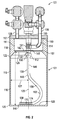
FIG. 1 is a side perspective view of a first embodiment of the vessel of the present invention; -
FIG. 2 is a sectional view, taken along line 2-2 ofFIG. 1 , of the first embodiment of the vessel of the present invention; -
FIG. 3 is a perspective side sectional view, taken along line 3-3 ofFIG. 1 , of the first embodiment of the vessel of the present invention; -
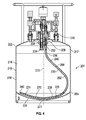
FIG. 4 is a side sectional view of a second embodiment of the vessel of the present invention; -
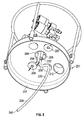
FIG. 5 is a partial perspective view the second embodiment of the vessel of the present invention, shown without the base portion and viewed from the bottom; -
FIG. 6 is a side sectional view of a third embodiment a vessel of the present invention; -
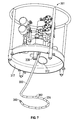
FIG. 7 is a partial perspective view of the third embodiment of the vessel of the present invention, shown without the base portion and viewed from the bottom; -
FIG. 8 is a partial perspective view of a fourth embodiment of the vessel of the present invention, shown without the base portion and viewed from the bottom; -
FIG. 9 is a side sectional view of the fourth embodiment of the vessel of the present invention; and -
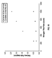
FIG. 10 is a graph showing the results of tests comparing the precursor delivery rate of the vessel of the present invention to that of a prior art vessel. - The ensuing detailed description provides preferred exemplary embodiments only, and is not intended to limit the scope, applicability, or configuration of the invention. Rather, the ensuing detailed description of the preferred exemplary embodiments will provide those skilled in the art with an enabling description for implementing the preferred exemplary embodiments of the invention.
- In the figures, elements that are similar to those of other embodiments of the present invention are represented by reference numerals increased by a value of 100. Such elements should be regarded as having the same function and features unless otherwise stated and/or depicted herein, and the discussion of such elements may therefore not be repeated for multiple embodiments. For example, the
inlet port 106 inFIG. 1 corresponds to theinlet port 206 inFIG. 4 . - The term "conduit," as used in the specification and claims, refers to one or more structures through which fluids can be transported between two or more components of a system. For example, conduits can include pipes, ducts, passageways, and combinations thereof that transport liquids, vapors, and/or gases.
- The term "flow communication," as used in the specification and claims, refers to the nature of connectivity between two or more components that enables liquids, vapors, and/or gases to be transported between the components in a controlled fashion (i.e., without leakage). Coupling two or more components such that they are in flow communication with each other can involve any suitable method known in the art, such as with the use of welds, flanged conduits, gaskets, and bolts. Two or more components may also be coupled together via other components of the system that may separate them.
- In order to aid in describing the invention, directional terms may be used in the specification and claims to describe portions of the present invention (e.g., upper, lower, left, right, etc.). These directional terms are merely intended to assist in describing and claiming the invention, and are not intended to limit the invention in any way. In addition, reference numerals that are introduced in the specification in association with a drawing figure may be repeated in one or more subsequent figures without additional description in the specification in order to provide context for other features.
- A vessel for the vaporization of a precursor material, particularly a solid precursor, and a method comprising same are disclosed herein. The vessel is typically constructed of a vessel having a base, lid, and sidewall that define an interior volume to contain the precursor material. Upon application of heat, the precursor material may transform from a solid and/or liquid phase to its gaseous phase. The precursor material may be a solid and/or a liquid. Examples of precursor materials that may be used in the vessel include, but are not limited to, dimethyl hydrazine, hafnium chloride (HfCl4), zirconium chloride (ZrCl4), tantalum chloride (TaCl5), MoCl5, WCl6, WCl5, WOCl4, NbCl5, indium trichloride, aluminum trichloride, gallium trichloride, titanium iodide, tungsten hexacarbonyl, molybdenum hexacarbonyl, decaborane, precursors incorporating alkyl-amidinate ligands, precursors such as zirconium tertiary butoxide (Zr(t-OBu)4), tetrakis(diethylamino) zirconium (Zr(NEt2)4), tetrakis(diethylamino) hafnium (Hf(NEt2)4), tetrakis(dimethylamino) titanium (TDMAT), tertbutyliminotris(diethylamino) tantalum (TBTDET), pentakis(dimethylamino) tantalum (PDMAT), pentakis (ethylmethylamino) tantalum (PEMAT), tetrakis(dimethylamino)zirconium (Zr(NMe2)4), and hafniumtertiarybutoxide (Hf(t-OBu)4), and mixtures thereof.
- In one embodiment, an inert carrier gas such as, for example, nitrogen, hydrogen, helium, argon, or other gas, is flowed through the interior volume and combines with the gaseous phase of the precursor material to provide a precursor-containing gaseous stream. In another embodiment, a vacuum may be used, alone or in conjunction with the inert gas, to withdraw the precursor-containing gaseous stream from the vessel. The precursor-containing gaseous stream may be then delivered to downstream production equipment, such as, for example, a reaction chamber for deposition. The vessel may provide for a continuous flow of precursor-containing gaseous stream while avoiding "cold spots" or other problems attributable to the condensation of vapors contained therein. The vessel may also provide a consistent and reproducible flow rate, which may be advantageous for a variety of manufacturing processes.
- Referring to
FIG. 1 ,vessel 101 has alid portion 117, abase portion 118,inlet port 106,outlet port 108, and a service port 110 (also referred to herein as a fill port). Althoughvessel 101 is substantially cylindrical in shape, in this embodiment, having asingle sidewall 119 and a substantially flat bottomexterior wall 120, it is understood thatvessel 101 has other shapes, such as a hollow square or spherical shape. - Referring to
FIG. 2 , thevessel 101 defines aprecursor chamber 116 to contain the precursor material (not shown).Lid portion 117,base portion 118, andseparator 142 may be constructed of a metal or other material that can withstand the operating temperatures ofvessel 101. In certain embodiments, at least a portion oflid portion 117 andbase portion 118 may be chemically non-reactive to the precursor material contained therein. In these or in alternative embodiments, at least a portion oflid portion 117,base portion 118, andsidewall 119 may be thermally conductive. Exemplary metals forlid portion 117,base portion 118, andsidewall 119 include stainless steel, nickel alloys (e.g., a Hastelloy® alloy, made by Haynes International, Inc.), titanium, chrome, zirconium, monel, impervious graphite, molybdenum, cobalt, anodized aluminum, aluminum alloys, silver, silver alloys, copper, copper alloys, lead, nickel clad steel, graphite, a ceramic material, doped or undoped, or combinations thereof. In one embodiment, at least a portion of the surface that contacts the precursor may be plated with various metals such as titanium, chrome, silver, tantalum, gold, platinum, titanium and other materials wherein the aforementioned plating materials can be doped or undoped to increase surface compatibility. In these embodiments, the plating material may be non-reactive to the precursor material contained therein. - In some embodiments, such as those depicted in
FIGS. 1 and2 ,inlet port 106 andoutlet port 108 may include valves that act to control the flow of fluid into and out ofvessel 101. Valves may be manual, automatic such as pneumatic, or the like and preferably are capable of operating at the operating temperatures of thevessel 101. In certain embodiments, valves may be fitted with disconnect fittings to facilitate removal ofvessel 101 from the process line. Brackets (not shown) to minimize the bending of theinlet port 106 andoutlet port 108 tubing may support valves. Further, the inlet and outlet tubing may be connected with a standard gas tight fitting, such as a VCR™ fitting manufactured by the Swagelok Company of Cleveland, Ohio, that is used to connect two separate pieces of piping. In some embodiments, theoutlet port 108 may have one or more filters that are placed in-line on the outlet tubing to remove any impurities or particulate matter from the precursor-containing fluid stream. Filters may be comprised of a porous material (not shown) that is chemically unreactive to the precursor-containing fluid stream and of sufficient particle size to capture any impurities or particulate matter in the precursor-containing fluid stream as it passes therethrough. - The
vessel 101 may further comprise a thermally conductive jacket that surrounds at least a portion ofvessel 101 and is retained by fasteners fitted in recesses, such as bolt and nut combinations to provide a snug fit. A thermally conductive jacket may allow for the uniform distribution of heat and improve the conduction of heat into the precursor material contained within the interior volume of thevessel 101. The jacket and fasteners may be comprised of a different material that allows for the expansion of the jacket upon heating. For example, the jacket may be comprised of aluminum whereas thesidewall 119 ofvessel 101 may be comprised of stainless steel. -
Vessel 101 and the precursor material contained therein are preferably heated to a temperature at which the vapor pressure from precursor sublimation is at least 2 Torr (0.27 kPa) and, more preferably, at least 10 Torr (1.33 kPa). Heating can be accomplished through a variety of means that include, but are not limited to, strip heaters, radiant heaters, circulating fluid heaters, resistant heating systems, inductive heating systems, or other means that can be used alone or in combination. These heating sources may be external and/or internal in relation tovessel 101. In some embodiments, theentire vessel 101 may be introduced into an oven or a water bath. In other embodiments,base portion 118 may have one or more heating elements of cartridges contained therein (not shown). Heating cartridges may be inserted into the interior volume ofvessel 101 in various places. Still other embodiments may employ one or more inductive heating coils operated by an RF power supply. Yet other embodiments may employ a heater that is in fluid communication with the carrier gas supply that heats the carrier gas to a certain temperature prior to introduction intovessel 101. -
Vessel 101 may further have one or more thermocouples, thermistors, or other temperature sensitive devices that can monitor the temperature ofvessel 101 and the precursor material contained therein. The one or more thermocouples may be located in thebase portion 118,lid portion 117,precursor chamber 116 and/or other areas of the vessel. The one or more thermocouples or other temperature sensitive devices may be connected to a controller or computer that is in electrical communication with the heating source to maintain a uniform temperature within theprecursor chamber 116 of the vessel and the chemical contained therein. - Referring to
FIG. 2 , thevessel 101 comprises abase portion 118 and alid portion 117.Lid portion 117 may be fastened onto thebase portion 118 through the one ormore fasteners 117a such as screws or pins (seeFIG. 1 ). The surface between thelid portion 117 and thebase portion 118 may be sealed by aseal 150 to form an air tight seal.Seal 150 may be a seal, o-ring, gasket, insert or the like which may be used to allowvessel 101 to maintain a vacuum or sustained pressure and may be constructed of a metal or a polymeric material. Alternatively,lid portion 117 and/orbase portion 118 may be aligned or welded ontosidewall 119 to form an airtight or pressure-tight seal without the need forseal 150. -
Inlet port 106 extends through thelid portion 117, turns viainlet bend 114, and connects to abody 131. Thebody 131 directs the carrier gas through theseparator 142. Thebody 131 comprises aflange 141 that forms a seal against theseparator 142 via friction fit. Thebody 131 further comprises acoupling 132 that extends below theseparator 142. Thebody 131 extends through a hole oraperture 149 in the center of theseparator 142 and thediffuser tube 130 is connected to thecoupling 132 at a joint 136, which is near the top of theprecursor chamber 116. Thediffuser tube 130 has a linearupper portion 146 that extends downwardly into theprecursor chamber 116 from a point nearcenterline 123 ofvessel 101, abend 148 that curves outwardly toward thesidewall 119, a secondlinear portion 158, and areverse curve 162 that curves back toward thecenterline 123, and then extends parallel to aninterior bottom surface 125 of abottom wall 120 of thevessel 101. - At the
end 140 of thediffuser tube 130, anozzle 138 comprises a plurality of nozzle openings (holes) 174 through which the carrier gas enters theprecursor chamber 116. In this embodiment, thenozzle openings 174 are preferably between 0.001 inches (0.0025 cm) and 0.25 inches (0.64 cm) in diameter and approximately 40 nozzle openings are located in the portion of thediffuser tube 130 that extends parallel to theinterior bottom surface 125 of thevessel 101. -
Nozzle openings 174 are preferably distributed evenly across theinterior bottom surface 125 of thevessel 101 to enable the best precursor utilization. Preferably thenozzle openings 174 are located along the sides of the nozzle 138 (only oneside 170 is visible in the figures) to direct carrier gas flow into as broad a swath of the precursor as possible so that the distributor does not quickly become uncovered with a premature sublimation of the precursor directly above thediffuser tube 130. Once thediffuser tube 130 is uncovered, the saturation of vapor in the carrier will quickly diminish and the mass flow drop will cause a process shutdown to replace thevessel 101 with another full vessel. Accordingly, in order to extend the life of thevessel 101 and to increase precursor utilization, thenozzle openings 174 are preferably spaced equally along the portion of thediffuser tube 130 in which theopenings 174 are located and the openings are preferably located in the bottom half section of the diffuser tube 130 (i.e., below the centerline of the diffuser tube 130). - As an alternative to providing the plurality of
nozzle openings 174, the portion of thediffuser tube 130 on which the plurality ofnozzle openings 174 is located could be replaced with a metal sintered frit welded or bonded to the end of thediffuser tube 130. One example of a suitable frit is a model 316L,Series 1200 porous stainless steel cup, made by the Mott Corporation. One benefit of using a frit (filter) instead of thenozzle openings 174 is that the frit performs a filtration function and prevents precursor material from being sucked into thediffuser tube 130 or any conduits upstream from thediffuser tube 130. It is not uncommon for thediffuser tube 130 to briefly pull a vacuum during the startup of the system of which thevessel 101 is a component. - The carrier gas exits through the
openings 174 in thenozzle 138 of thediffuser tube 130 and migrates up through a bed of solid precursor particles (not shown). As the carrier gas diffuses up through the precursor, it mixes with sublimated precursor and passes through the separator (filter disk) 142 prior to exiting thevessel 101 through theoutlet port 108. - In the first embodiment,
separator 142 is provided to prevent unsublimated precursor from mixing with the outgoing precursor-containing fluid stream.FIGS. 2 and3 provide an illustration ofseparator 142 that rests onupper lip 151 of thebase portion 118 and acts to partition the interior volume of thevessel 101 into upper volume 111 (also referred to as an outlet chamber, or an inlet chamber) and a lower volume 116 (also referred to as a precursor chamber).Separator 142 defines the dividing line between the upper volume 111 and thelower volume 116. - The separator can be any planar separator as described above, but one embodiment could be a 3.9 inch (9.91 cm) diameter 316L stainless steel filter disk fabricated from porous sheet material having a thickness of 0.047 inches (0.12 cm), and having 99.9% efficiency for particles of 0.7µM size, 99.0% efficiency for particles of 0.35µM and 90% efficiency for all particle sizes, and with a bubble point of 2.0-2.5 Hg.
- Depending upon the precursor, there may be a need to stop the entrainment of solid in the outgoing precursor-containing fluid stream. In these embodiments,
vessel 101 may further include an optionalstainless steel filter 239 or frit (seeFIG. 4 ), which may prevent unsublimated precursor from entering the outgoing precursor-containing fluid stream. The optional stainless steel frit may have a pore size that ranges from 0.1 to 100 microns. The optional frit can be installed in the upper volume 111 and/or the fluid path of the outgoing precursor-containing fluid. In some embodiments, a filter is installed on the outlet port 108 (see, e.g.,filter 239 is installed on theoutlet port 208 inFIG. 4 ). - Operating temperatures of the
vessel 101 may vary depending upon the precursor material contained therein but may generally range from about 25 degrees Celsius to about 500 degrees Celsius, or from about 100 degrees Celsius to about 300 degrees Celsius. Operating pressure of the vessel may range from about 2 Torr to about 1,000 Torr (270 Pa to 130 kPa), or from about 0.1 Torr to about 200 Torr (13 Pa to 27 kPa). In many applications, a pressure range of 10 to 200 Torr (1.3 kPa to 27 kPa) is preferable. - In one embodiment, the method of using the
vessel 101 includes introducing a precursor material, such as a solid precursor material, throughservice port 110 and into theprecursor chamber 116 ofvessel 101. It is preferable that the precursor material is filled to the point where it is in continuous contact with at least a portion of thediffuser tube 130. More preferably, the precursor covers thenozzle 138 of thediffuser tube 130. Thelid portion 117 andbase portion 118 are fastened to provide a pressure-tight orairtight seal 150. - A heating source, such as heating cartridges, is used to bring the precursor material to sublimation temperature and form a precursor gas. The inert carrier gas enters through
inlet port 106, travels through thediffuser tube 130, and combines with the precursor gas to form the precursor-containing fluid stream. The precursor-containing fluid stream passes throughseparator 142 andoutlet port 108 and through in-line filters (not shown) to a down-stream production device such as a reaction chamber used for thin film deposition. - It is beneficial to build, clean, purge, dry, and leak check the
vessel 101 first. Then the solid precursor particles are loaded through theservice port 110 via gravity. Theservice port 110 is located on thelid portion 117 and the service port chute extends down into the precursor chamber at theshoulder 122 of thevessel 101, which is below and outside the perimeter of theseparator 142. This allows for filling of the precursor and cleaning or otherwise servicing or inspecting thevessel 101 without having to remove thelid portion 117 and disassemble thebody 131,separator 142, anddiffuser tube 130. - The
precursor chamber 116 has alower radius 127 that is preferably at least 10% larger (more preferably, at least 20% larger) than theupper radius 126, near theseparator 142. This difference allows theshoulder 122 to be thick enough to have aservice port chute 112, which bypasses theseparator 142 and is aligned with theservice port 110, framed therein. -
FIG. 4 shows a side sectional view of a second embodiment of thevessel 201, which is a bulk container for solid-source precursor. In this embodiment, thebottom wall 220 of thevessel 201 has a curved interiorbottom surface 225. Thesidewall 219 of thevessel 201 meets the curved interiorbottom surface 225 at thebottom shoulder 265. In this embodiment, theinterior bottom surface 225 has the shape of a partial sphere. This shape enables thewalls 219 of thevessel 201 to be thinner (and therefore, lighter) than if theinterior bottom surface 225 were substantially planar. Benefits of a non-planarinterior bottom surface 225 could also be achieved with other curved shapes, such as partial spheroid shapes. As used in the specification and claims, a partial spheroid shaped surface is intended to refer to both partial spheroid and partial sphere shapes. - In the embodiment, the
diffuser tube 230 is mounted near thecenterline 223 of thevessel 201 and it extends downward toward theinterior bottom surface 225 of thevessel 201. Thediffuser tube 230 follows anupper bend 248 and a middlestraight portion 258 extends toward thesidewall 219 of thevessel 201 and follows alower bend 262 downward along theinterior bottom surface 225 of thevessel 201. Thenozzle 238 of the diffuser tube follows the curvature of theinterior bottom surface 225 of thevessel 201. The plurality ofopenings 274 on thenozzle 238 are below thebottom shoulder 265 ofvessel 201. Thenozzle 238 extends along thelowest point 277 of theinterior bottom surface 225 of thevessel 201. This results in a high utilization of precursor, meaning that a low percentage of precursor is left behind in thevessel 201. - In this embodiment, it is desirable for the nozzle 238 (also referred to as the distal end) of the
diffuser tube 230 to follow the shape of the portion of theinterior bottom surface 225 that is below thenozzle 238. Accordingly, in this embodiment, thenozzle 238 has an arcuate shape. - The
vessel 201 has a larger internal volume than the first embodiment. As this embodiment need not have a disk separator (see 142 ofFIGS. 2-3 ) that defines a lower volume and an upper volume, the entire inner volume of thevessel 201 may be theprecursor volume 216. -
FIG. 5 shows a bottom perspective view of thelid portion 217 of a second embodiment of thevessel 201. Theinlet port 206 extends through thelid portion 217 and is connected to thediffuser tube 230 by acoupling 232. Theoutlet port 208 comprises afilter 239 and extends through thelid portion 217. Theservice port chute 212 extends through thelid portion 217, allowing for precursor fills without removing the lid or disconnecting any inlet or outlet piping. In this embodiment,ports -
FIGS. 6 and7 show a side sectional view and bottom perspective view, respectively, of a third embodiment of thevessel 301. In this embodiment, thediffuser tube 330 curves away from thecenterline 323 of thevessel 301 and extends toward theinterior bottom surface 325 forming a bottomcurved portion 362. The bottomcurved portion 362 is substantially horizontal and ring shaped and sits below thebottom shoulder 365 of thevessel 301. -
FIGS. 8 and9 show a bottom perspective view of thelid portion 417 and a side sectional view, respectively, of a fourth embodiment of thevessel 401. Thediffuser tube 430 curves away from thecenterline 423 of thevessel 401 and extends down toward the interior bottom surface of thevessel 401 forming a substantially horizontal ring with asecondary nozzle bend 475 that overlaps the generally horizontal portion. Theentire nozzle 438 of thediffuser tube 440 sits below thebottom shoulder 465 of thevessel 401. Thesecondary nozzle bend 475 extends along thelowest point 477 of the interior bottom surface of thevessel 401. This results in a high utilization of precursor which lowers production costs and reduces the equipment downtime associated with replacing thevessel 401 with avessel 401 filled with precursor. - In order to demonstrate the advantages of the present invention, two tests were performed. Test 1 was performed using the
vessel 101 shown inFIGS. 1-4 , which includes on thecurved diffuser tube 130 having a plurality of the nozzle openings 174 (see, e.g.,FIG. 2 ). Test 2 was performed using the prior art vessel described inU.S. Patent No. 9,109,287 diffuser tube 130 is not provided), but is otherwise identical to thevessel 101 shown inFIGS. 1-4 . This results in carrier gas being introduced into the lower portion of the container only above theseparator 142. - Both of the tests were performed by introducing one kilogram of solid precursor tantalum chloride (TaCl5) into the vessel, then placing the vessel in an oven heated to 90 degrees Celsius on an aluminum plate maintained at 80 degrees Celsius. This temperature gradient was maintained to avoid solid condensation on the
separator 142. During the tests, downstream pressure was maintained at 100 torr and a nitrogen carrier gas was pulsed at 10 second intervals, alternating between a bypass and theinlet port 106. The test was repeated on each vessel at four different carrier gas flow rates, 250, 500, 750, and 1000 standard cubic centimeters per minute (sccm). - Delivery rates of tantalum chloride precursor for both vessels were measured. measured using a Piezocon gas concentration sensor and the data is shown in
FIG. 10 . As shown inFIG. 10 , thevessel 101 of present invention provided up to six times higher delivery rates of tantalum chloride than the vessel of the prior art. - While the principles of the claimed invention have been described above in connection with preferred embodiments, it is to be clearly understood that this description is made only by way of example and not as a limitation of the scope of the claimed invention.
Claims (15)
- A vessel for conveying a precursor-containing fluid stream from a precursor material contained within the vessel using a carrier gas, the vessel comprising:an interior volume segmented into an upper volume and a lower volume, the lower volume containing substantially all of the precursor material;a lid that defines at least a portion of the upper volume;a sidewall having an upper end comprising an upper lip and an upper opening, wherein at least a portion of the upper lip contacts the lid;a base that defines a portion of the lower volume, the base including an interior bottom surface that defines a lower end of the lower volume, the interior bottom surface having an interior bottom surface shape;a separator located at the upper end of the sidewall, interposed between the lid and the sidewall, and spanning the upper opening, the separator being formed of a porous material and having a first aperture formed therein;an inlet that passes through the lid and is in fluid communication with the interior volume, the inlet having a body that extends from the lid to the separator, the body, the separator and the lid defining an outlet chamber that is external to the body, within the lid and above the separator;a diffuser tube having a proximal end that is in fluid communication with the inlet and a distal end that is located with the lower volume, the distal end comprising a nozzle portion having a plurality of openings formed therein and a nozzle portion shape; andan outlet that passes through the lid and is in fluid communication with the interior volume, the outlet having at least one opening, each of the at least one opening being located within the outlet chamber;wherein the separator and inlet are operationally configured to prevent flow communication from the lower volume into the outlet chamber except through the separator.
- The vessel of claim 1, wherein the porous material of the separator has a filtration efficiency of at least 90% for particles having a particle size of at least 0.7 µm.
- The vessel of claim 1 or 2, further comprising a fill port that passes through the lid and terminates at a chute located along the sidewall within the lower volume, the fill port being in fluid communication with the interior volume and bypassing the separator.
- The vessel of claim 3, wherein the lower volume has a lower radius that is larger than an upper radius of the upper lip of the sidewall, thereby defining a shoulder portion of the sidewall.
- The vessel of claim 4, wherein the lower radius is at least 20% larger than the upper radius.
- The vessel of claim 4 or 5, wherein the chute is located in the shoulder portion.
- The vessel of any one of the preceding claims, wherein the nozzle portion shape is substantially the same as the interior bottom surface shape.
- The vessel of any one of the preceding claims, wherein the nozzle portion shape and the interior bottom surface shape are both concave.
- The vessel of any one of the preceding claims, wherein the inlet further comprises a coupler located below the separator, the diffuser tube attached to and detachable from the coupler.
- The vessel of any one of the preceding claims, wherein the body further comprises a flange that is sized and positioned to form a seal between the flange and the separator, thereby preventing flow communication from the lower volume to the outlet chamber through the first aperture.
- A vessel for conveying a precursor-containing fluid stream from a solid precursor material contained within the vessel using a carrier gas, the vessel comprising:a lid, a sidewall having an upper end that contacts the lid, and a base including an interior bottom surface, the lid, sidewall and base defining an interior volume, the interior bottom surface having a concave shape;a fill port that passes through the lid and is in fluid communication with the interior volume;an inlet that passes through the lid and is in fluid communication with the interior volume;a diffuser tube that is in fluid communication with the inlet and is located in the interior volume, the diffuser includes a proximal end and a distal end, the distal end including a nozzle portion having a plurality of openings formed therein, the nozzle portion having a non-linear nozzle portion shape; andan outlet that passes through the lid and is in fluid communication with the interior volume, the outlet having at least one opening having a filter thereon.
- A method comprising:(a) providing the vessel of any one of claims 1 to 10;(b) at least partially filling the lower volume with the precursor material;(c) supplying a carrier gas through a nozzle that is submerged in the precursor material at the commencement of step (c); and(d) removing a precursor-containing fluid stream from the outlet.
- The method of claim 12, wherein:the vessel has a fill port as recited in claim 3;step (a) comprises assembling the lid, sidewall and base before performing any of steps (b) through (d); andstep (b) comprises at least partially filling the lower volume with the precursor material using the fill port and without removing the lid from the sidewall.
- The method of claim 12 or 13, further comprising:(e) after performing steps (b) through (d), cleaning the lower volume without removing the lid from the sidewall.
- The method of any one of claims 12 to 14, wherein step (b) further comprises:(b) at least partially filling the lower volume with the precursor material, the precursor material selected from the group of: hafnium chloride (HfCl4), zirconium chloride (ZrCl4), tantalum chloride (TaCl5), MoCl5, WCl6, WCl5, WOCl4, NbCl5, indium trichloride, aluminum trichloride, gallium trichloride, titanium iodide, tungsten hexacarbonyl, molybdenum hexacarbonyl, decaborane, precursors incorporating alkyl-amidinate ligands, precursors such as zirconium tertiary butoxide (Zr(t-OBu)4), tetrakis(diethylamino) zirconium (Zr(NEt2)4), tetrakis(diethylamino) hafnium (Hf(NEt2)4), tetrakis(dimethylamino) titanium (TDMAT), tertbutyliminotris(diethylamino) tantalum (TBTDET), pentakis(dimethylamino) tantalum (PDMAT), pentakis (ethylmethylamino) tantalum (PEMAT), tetrakis(dimethylamino)zirconium (Zr(NMe2)4), hafniumtertiarybutoxide (Hf(t-OBu)4), and mixtures thereof.
Applications Claiming Priority (2)
| Application Number | Priority Date | Filing Date | Title |
|---|---|---|---|
| US201562149548P | 2015-04-18 | 2015-04-18 | |
| US15/094,551 US10443128B2 (en) | 2015-04-18 | 2016-04-08 | Vessel and method for delivery of precursor materials |
Publications (2)
| Publication Number | Publication Date |
|---|---|
| EP3081668A1 true EP3081668A1 (en) | 2016-10-19 |
| EP3081668B1 EP3081668B1 (en) | 2021-08-25 |
Family
ID=56292423
Family Applications (1)
| Application Number | Title | Priority Date | Filing Date |
|---|---|---|---|
| EP16165879.4A Active EP3081668B1 (en) | 2015-04-18 | 2016-04-18 | Vessel and method for delivery of precursor materials |
Country Status (7)
| Country | Link |
|---|---|
| US (1) | US10443128B2 (en) |
| EP (1) | EP3081668B1 (en) |
| JP (1) | JP6228257B2 (en) |
| KR (3) | KR20160124031A (en) |
| CN (3) | CN106048558A (en) |
| SG (1) | SG10201602945XA (en) |
| TW (1) | TWI615498B (en) |
Cited By (2)
| Publication number | Priority date | Publication date | Assignee | Title |
|---|---|---|---|---|
| US10141209B2 (en) * | 2014-02-28 | 2018-11-27 | Tokyo Electron Limited | Processing gas generating apparatus, processing gas generating method, substrate processing method, and storage medium |
| US11873558B2 (en) | 2021-09-07 | 2024-01-16 | Picosun Oy | Precursor container |
Families Citing this family (15)
| Publication number | Priority date | Publication date | Assignee | Title |
|---|---|---|---|---|
| US10100406B2 (en) * | 2015-04-17 | 2018-10-16 | Versum Materials Us, Llc | High purity tungsten hexachloride and method for making same |
| WO2017062670A1 (en) * | 2015-10-06 | 2017-04-13 | Entegris, Inc. | Cold sintering of solid precursors |
| EP3162914A1 (en) * | 2015-11-02 | 2017-05-03 | IMEC vzw | Apparatus and method for delivering a gaseous precursor to a reaction chamber |
| US10871238B2 (en) * | 2017-07-18 | 2020-12-22 | Versum Materials Us, Llc | Removable valve guard for ampoules |
| WO2019023011A1 (en) * | 2017-07-25 | 2019-01-31 | Linde Aktiengesellschaft | Solid composition sublimer apparatus, systems, and methods of using same |
| US11634812B2 (en) | 2018-08-16 | 2023-04-25 | Asm Ip Holding B.V. | Solid source sublimator |
| JP7284265B2 (en) * | 2018-12-11 | 2023-05-30 | アプライド マテリアルズ インコーポレイテッド | Ampoule droplet reduction |
| JP6887688B2 (en) * | 2019-02-07 | 2021-06-16 | 株式会社高純度化学研究所 | A container for evaporative raw materials and a solid vaporization supply system using the container for evaporative raw materials |
| JP6901153B2 (en) * | 2019-02-07 | 2021-07-14 | 株式会社高純度化学研究所 | Solid vaporization supply system for metal halogen compounds for thin film formation. |
| CN113994460B (en) * | 2019-04-15 | 2025-05-20 | 朗姆研究公司 | Modular component system for gas transport |
| US20210071301A1 (en) * | 2019-09-10 | 2021-03-11 | Asm Ip Holding B.V. | Fill vessels and connectors for chemical sublimators |
| US11624113B2 (en) * | 2019-09-13 | 2023-04-11 | Asm Ip Holding B.V. | Heating zone separation for reactant evaporation system |
| KR102272808B1 (en) | 2019-11-22 | 2021-07-02 | 세종대학교산학협력단 | Flattening apparatus and substrate processing apparatus including the same, substrate processing method |
| JP7699514B2 (en) * | 2021-09-30 | 2025-06-27 | 株式会社キッツエスシーティー | Valve unit for raw material container |
| USD1098060S1 (en) * | 2024-02-05 | 2025-10-14 | Asm Ip Holding B.V. | Precursor vessel nozzle |
Citations (4)
| Publication number | Priority date | Publication date | Assignee | Title |
|---|---|---|---|---|
| WO1994021840A1 (en) * | 1993-03-18 | 1994-09-29 | Advanced Technology Materials, Inc. | Apparatus and method for delivering reagents in vapor form to a cvd reactor |
| US20120266967A1 (en) * | 2009-11-02 | 2012-10-25 | Sigma-Aldrich Co. Llc | Evaporator |
| US20140191423A1 (en) * | 2006-12-15 | 2014-07-10 | Air Products And Chemicals, Inc. | Splashguard and Inlet Diffuser for High Vacuum, High Flow Bubbler Vessel |
| US9109287B2 (en) | 2006-10-19 | 2015-08-18 | Air Products And Chemicals, Inc. | Solid source container with inlet plenum |
Family Cites Families (22)
| Publication number | Priority date | Publication date | Assignee | Title |
|---|---|---|---|---|
| US3993094A (en) * | 1975-04-21 | 1976-11-23 | Allis-Chalmers Corporation | Removable reservoir cover having internal parts of reservoir mounted thereon |
| US4915880A (en) | 1989-05-22 | 1990-04-10 | Advanced Delivery & Chemical Systems Incorporated | Container for a bubbler |
| US5078922A (en) | 1990-10-22 | 1992-01-07 | Watkins-Johnson Company | Liquid source bubbler |
| JPH05335243A (en) | 1992-06-03 | 1993-12-17 | Mitsubishi Electric Corp | Liquid bubbling apparatus |
| JPH06267852A (en) | 1993-03-12 | 1994-09-22 | Hitachi Ltd | Liquid raw material vaporizer |
| US6444038B1 (en) | 1999-12-27 | 2002-09-03 | Morton International, Inc. | Dual fritted bubbler |
| JP3909792B2 (en) | 1999-08-20 | 2007-04-25 | パイオニア株式会社 | Raw material supply apparatus and raw material supply method in chemical vapor deposition |
| KR100360494B1 (en) * | 1999-09-21 | 2002-11-13 | 삼성전자 주식회사 | Bubbler |
| GB9929279D0 (en) | 1999-12-11 | 2000-02-02 | Epichem Ltd | An improved method of and apparatus for the delivery of precursors in the vapour phase to a plurality of epitaxial reactor sites |
| US7077388B2 (en) | 2002-07-19 | 2006-07-18 | Asm America, Inc. | Bubbler for substrate processing |
| US6915592B2 (en) | 2002-07-29 | 2005-07-12 | Applied Materials, Inc. | Method and apparatus for generating gas to a processing chamber |
| US7261118B2 (en) * | 2003-08-19 | 2007-08-28 | Air Products And Chemicals, Inc. | Method and vessel for the delivery of precursor materials |
| US7722720B2 (en) | 2004-12-08 | 2010-05-25 | Rohm And Haas Electronic Materials Llc | Delivery device |
| KR20060118819A (en) * | 2005-05-17 | 2006-11-24 | 한국기계연구원 | Liquid substance vaporizer |
| US20080241805A1 (en) | 2006-08-31 | 2008-10-02 | Q-Track Corporation | System and method for simulated dosimetry using a real time locating system |
| TW201040306A (en) * | 2009-03-11 | 2010-11-16 | Air Liquide | Bubbling supply system for stable precursor supply |
| US8944420B2 (en) | 2009-03-19 | 2015-02-03 | Air Products And Chemicals, Inc. | Splashguard for high flow vacuum bubbler vessel |
| JP6039203B2 (en) * | 2011-05-23 | 2016-12-07 | キヤノン株式会社 | Image output apparatus, image output apparatus control method, and program |
| TWI480418B (en) * | 2012-01-16 | 2015-04-11 | Air Prod & Chem | Splashguard for high flow vacuum bubbler vessel |
| JP5761067B2 (en) * | 2012-02-13 | 2015-08-12 | 東京エレクトロン株式会社 | Gas supply device and heat treatment device |
| TWI516432B (en) * | 2012-09-13 | 2016-01-11 | 南美特科技股份有限公司 | Delivery equipment for the solid precursor particles |
| KR101673349B1 (en) | 2015-03-20 | 2016-11-07 | 현대자동차 주식회사 | Engine clutch control system for hybrid vehicle and method thereof |
-
2016
- 2016-04-08 US US15/094,551 patent/US10443128B2/en active Active
- 2016-04-14 SG SG10201602945XA patent/SG10201602945XA/en unknown
- 2016-04-15 TW TW105111934A patent/TWI615498B/en not_active IP Right Cessation
- 2016-04-15 JP JP2016081953A patent/JP6228257B2/en active Active
- 2016-04-18 EP EP16165879.4A patent/EP3081668B1/en active Active
- 2016-04-18 CN CN201610244829.5A patent/CN106048558A/en active Pending
- 2016-04-18 CN CN202210314638.7A patent/CN114657539A/en active Pending
- 2016-04-18 KR KR1020160047065A patent/KR20160124031A/en not_active Ceased
- 2016-04-18 CN CN201910951469.6A patent/CN110551989A/en active Pending
-
2018
- 2018-06-20 KR KR1020180070859A patent/KR20180074632A/en not_active Ceased
-
2022
- 2022-02-21 KR KR1020220022247A patent/KR102445312B1/en active Active
Patent Citations (4)
| Publication number | Priority date | Publication date | Assignee | Title |
|---|---|---|---|---|
| WO1994021840A1 (en) * | 1993-03-18 | 1994-09-29 | Advanced Technology Materials, Inc. | Apparatus and method for delivering reagents in vapor form to a cvd reactor |
| US9109287B2 (en) | 2006-10-19 | 2015-08-18 | Air Products And Chemicals, Inc. | Solid source container with inlet plenum |
| US20140191423A1 (en) * | 2006-12-15 | 2014-07-10 | Air Products And Chemicals, Inc. | Splashguard and Inlet Diffuser for High Vacuum, High Flow Bubbler Vessel |
| US20120266967A1 (en) * | 2009-11-02 | 2012-10-25 | Sigma-Aldrich Co. Llc | Evaporator |
Cited By (3)
| Publication number | Priority date | Publication date | Assignee | Title |
|---|---|---|---|---|
| US10141209B2 (en) * | 2014-02-28 | 2018-11-27 | Tokyo Electron Limited | Processing gas generating apparatus, processing gas generating method, substrate processing method, and storage medium |
| US11873558B2 (en) | 2021-09-07 | 2024-01-16 | Picosun Oy | Precursor container |
| US12146218B2 (en) | 2021-09-07 | 2024-11-19 | Picosun Oy | Precursor container |
Also Published As
| Publication number | Publication date |
|---|---|
| JP2016208026A (en) | 2016-12-08 |
| KR20220025794A (en) | 2022-03-03 |
| EP3081668B1 (en) | 2021-08-25 |
| CN106048558A (en) | 2016-10-26 |
| US10443128B2 (en) | 2019-10-15 |
| KR20160124031A (en) | 2016-10-26 |
| TW201641737A (en) | 2016-12-01 |
| CN114657539A (en) | 2022-06-24 |
| KR20180074632A (en) | 2018-07-03 |
| JP6228257B2 (en) | 2017-11-08 |
| US20160305019A1 (en) | 2016-10-20 |
| CN110551989A (en) | 2019-12-10 |
| SG10201602945XA (en) | 2016-11-29 |
| KR102445312B1 (en) | 2022-09-19 |
| TWI615498B (en) | 2018-02-21 |
Similar Documents
| Publication | Publication Date | Title |
|---|---|---|
| EP3081668B1 (en) | Vessel and method for delivery of precursor materials | |
| US9598766B2 (en) | Vessel with filter | |
| EP1508631B1 (en) | Method and apparatus for the delivery of precursor materials | |
| US9109287B2 (en) | Solid source container with inlet plenum | |
| JP5898624B2 (en) | Evaporator | |
| WO2007109410A2 (en) | Method and apparatus for reducing particle contamination in a deposition system |
Legal Events
| Date | Code | Title | Description |
|---|---|---|---|
| PUAI | Public reference made under article 153(3) epc to a published international application that has entered the european phase |
Free format text: ORIGINAL CODE: 0009012 |
|
| AK | Designated contracting states |
Kind code of ref document: A1 Designated state(s): AL AT BE BG CH CY CZ DE DK EE ES FI FR GB GR HR HU IE IS IT LI LT LU LV MC MK MT NL NO PL PT RO RS SE SI SK SM TR |
|
| AX | Request for extension of the european patent |
Extension state: BA ME |
|
| STAA | Information on the status of an ep patent application or granted ep patent |
Free format text: STATUS: REQUEST FOR EXAMINATION WAS MADE |
|
| 17P | Request for examination filed |
Effective date: 20170419 |
|
| RBV | Designated contracting states (corrected) |
Designated state(s): AL AT BE BG CH CY CZ DE DK EE ES FI FR GB GR HR HU IE IS IT LI LT LU LV MC MK MT NL NO PL PT RO RS SE SI SK SM TR |
|
| RAP1 | Party data changed (applicant data changed or rights of an application transferred) |
Owner name: VERSUM MATERIALS US, LLC |
|
| STAA | Information on the status of an ep patent application or granted ep patent |
Free format text: STATUS: EXAMINATION IS IN PROGRESS |
|
| 17Q | First examination report despatched |
Effective date: 20180713 |
|
| GRAP | Despatch of communication of intention to grant a patent |
Free format text: ORIGINAL CODE: EPIDOSNIGR1 |
|
| STAA | Information on the status of an ep patent application or granted ep patent |
Free format text: STATUS: GRANT OF PATENT IS INTENDED |
|
| INTG | Intention to grant announced |
Effective date: 20210309 |
|
| GRAS | Grant fee paid |
Free format text: ORIGINAL CODE: EPIDOSNIGR3 |
|
| GRAA | (expected) grant |
Free format text: ORIGINAL CODE: 0009210 |
|
| STAA | Information on the status of an ep patent application or granted ep patent |
Free format text: STATUS: THE PATENT HAS BEEN GRANTED |
|
| AK | Designated contracting states |
Kind code of ref document: B1 Designated state(s): AL AT BE BG CH CY CZ DE DK EE ES FI FR GB GR HR HU IE IS IT LI LT LU LV MC MK MT NL NO PL PT RO RS SE SI SK SM TR |
|
| REG | Reference to a national code |
Ref country code: CH Ref legal event code: EP |
|
| REG | Reference to a national code |
Ref country code: IE Ref legal event code: FG4D Ref country code: AT Ref legal event code: REF Ref document number: 1423880 Country of ref document: AT Kind code of ref document: T Effective date: 20210915 |
|
| REG | Reference to a national code |
Ref country code: DE Ref legal event code: R096 Ref document number: 602016062617 Country of ref document: DE |
|
| REG | Reference to a national code |
Ref country code: LT Ref legal event code: MG9D |
|
| REG | Reference to a national code |
Ref country code: NL Ref legal event code: MP Effective date: 20210825 |
|
| REG | Reference to a national code |
Ref country code: AT Ref legal event code: MK05 Ref document number: 1423880 Country of ref document: AT Kind code of ref document: T Effective date: 20210825 |
|
| PG25 | Lapsed in a contracting state [announced via postgrant information from national office to epo] |
Ref country code: BG Free format text: LAPSE BECAUSE OF FAILURE TO SUBMIT A TRANSLATION OF THE DESCRIPTION OR TO PAY THE FEE WITHIN THE PRESCRIBED TIME-LIMIT Effective date: 20211125 Ref country code: AT Free format text: LAPSE BECAUSE OF FAILURE TO SUBMIT A TRANSLATION OF THE DESCRIPTION OR TO PAY THE FEE WITHIN THE PRESCRIBED TIME-LIMIT Effective date: 20210825 Ref country code: LT Free format text: LAPSE BECAUSE OF FAILURE TO SUBMIT A TRANSLATION OF THE DESCRIPTION OR TO PAY THE FEE WITHIN THE PRESCRIBED TIME-LIMIT Effective date: 20210825 Ref country code: NO Free format text: LAPSE BECAUSE OF FAILURE TO SUBMIT A TRANSLATION OF THE DESCRIPTION OR TO PAY THE FEE WITHIN THE PRESCRIBED TIME-LIMIT Effective date: 20211125 Ref country code: PT Free format text: LAPSE BECAUSE OF FAILURE TO SUBMIT A TRANSLATION OF THE DESCRIPTION OR TO PAY THE FEE WITHIN THE PRESCRIBED TIME-LIMIT Effective date: 20211227 Ref country code: FI Free format text: LAPSE BECAUSE OF FAILURE TO SUBMIT A TRANSLATION OF THE DESCRIPTION OR TO PAY THE FEE WITHIN THE PRESCRIBED TIME-LIMIT Effective date: 20210825 Ref country code: ES Free format text: LAPSE BECAUSE OF FAILURE TO SUBMIT A TRANSLATION OF THE DESCRIPTION OR TO PAY THE FEE WITHIN THE PRESCRIBED TIME-LIMIT Effective date: 20210825 Ref country code: RS Free format text: LAPSE BECAUSE OF FAILURE TO SUBMIT A TRANSLATION OF THE DESCRIPTION OR TO PAY THE FEE WITHIN THE PRESCRIBED TIME-LIMIT Effective date: 20210825 Ref country code: SE Free format text: LAPSE BECAUSE OF FAILURE TO SUBMIT A TRANSLATION OF THE DESCRIPTION OR TO PAY THE FEE WITHIN THE PRESCRIBED TIME-LIMIT Effective date: 20210825 Ref country code: HR Free format text: LAPSE BECAUSE OF FAILURE TO SUBMIT A TRANSLATION OF THE DESCRIPTION OR TO PAY THE FEE WITHIN THE PRESCRIBED TIME-LIMIT Effective date: 20210825 |
|
| PG25 | Lapsed in a contracting state [announced via postgrant information from national office to epo] |
Ref country code: PL Free format text: LAPSE BECAUSE OF FAILURE TO SUBMIT A TRANSLATION OF THE DESCRIPTION OR TO PAY THE FEE WITHIN THE PRESCRIBED TIME-LIMIT Effective date: 20210825 Ref country code: LV Free format text: LAPSE BECAUSE OF FAILURE TO SUBMIT A TRANSLATION OF THE DESCRIPTION OR TO PAY THE FEE WITHIN THE PRESCRIBED TIME-LIMIT Effective date: 20210825 Ref country code: GR Free format text: LAPSE BECAUSE OF FAILURE TO SUBMIT A TRANSLATION OF THE DESCRIPTION OR TO PAY THE FEE WITHIN THE PRESCRIBED TIME-LIMIT Effective date: 20211126 |
|
| PG25 | Lapsed in a contracting state [announced via postgrant information from national office to epo] |
Ref country code: NL Free format text: LAPSE BECAUSE OF FAILURE TO SUBMIT A TRANSLATION OF THE DESCRIPTION OR TO PAY THE FEE WITHIN THE PRESCRIBED TIME-LIMIT Effective date: 20210825 |
|
| PG25 | Lapsed in a contracting state [announced via postgrant information from national office to epo] |
Ref country code: DK Free format text: LAPSE BECAUSE OF FAILURE TO SUBMIT A TRANSLATION OF THE DESCRIPTION OR TO PAY THE FEE WITHIN THE PRESCRIBED TIME-LIMIT Effective date: 20210825 |
|
| REG | Reference to a national code |
Ref country code: DE Ref legal event code: R097 Ref document number: 602016062617 Country of ref document: DE |
|
| PG25 | Lapsed in a contracting state [announced via postgrant information from national office to epo] |
Ref country code: SM Free format text: LAPSE BECAUSE OF FAILURE TO SUBMIT A TRANSLATION OF THE DESCRIPTION OR TO PAY THE FEE WITHIN THE PRESCRIBED TIME-LIMIT Effective date: 20210825 Ref country code: SK Free format text: LAPSE BECAUSE OF FAILURE TO SUBMIT A TRANSLATION OF THE DESCRIPTION OR TO PAY THE FEE WITHIN THE PRESCRIBED TIME-LIMIT Effective date: 20210825 Ref country code: RO Free format text: LAPSE BECAUSE OF FAILURE TO SUBMIT A TRANSLATION OF THE DESCRIPTION OR TO PAY THE FEE WITHIN THE PRESCRIBED TIME-LIMIT Effective date: 20210825 Ref country code: EE Free format text: LAPSE BECAUSE OF FAILURE TO SUBMIT A TRANSLATION OF THE DESCRIPTION OR TO PAY THE FEE WITHIN THE PRESCRIBED TIME-LIMIT Effective date: 20210825 Ref country code: CZ Free format text: LAPSE BECAUSE OF FAILURE TO SUBMIT A TRANSLATION OF THE DESCRIPTION OR TO PAY THE FEE WITHIN THE PRESCRIBED TIME-LIMIT Effective date: 20210825 Ref country code: AL Free format text: LAPSE BECAUSE OF FAILURE TO SUBMIT A TRANSLATION OF THE DESCRIPTION OR TO PAY THE FEE WITHIN THE PRESCRIBED TIME-LIMIT Effective date: 20210825 |
|
| PLBE | No opposition filed within time limit |
Free format text: ORIGINAL CODE: 0009261 |
|
| STAA | Information on the status of an ep patent application or granted ep patent |
Free format text: STATUS: NO OPPOSITION FILED WITHIN TIME LIMIT |
|
| PG25 | Lapsed in a contracting state [announced via postgrant information from national office to epo] |
Ref country code: IT Free format text: LAPSE BECAUSE OF FAILURE TO SUBMIT A TRANSLATION OF THE DESCRIPTION OR TO PAY THE FEE WITHIN THE PRESCRIBED TIME-LIMIT Effective date: 20210825 |
|
| 26N | No opposition filed |
Effective date: 20220527 |
|
| PG25 | Lapsed in a contracting state [announced via postgrant information from national office to epo] |
Ref country code: SI Free format text: LAPSE BECAUSE OF FAILURE TO SUBMIT A TRANSLATION OF THE DESCRIPTION OR TO PAY THE FEE WITHIN THE PRESCRIBED TIME-LIMIT Effective date: 20210825 |
|
| REG | Reference to a national code |
Ref country code: CH Ref legal event code: PL |
|
| REG | Reference to a national code |
Ref country code: BE Ref legal event code: MM Effective date: 20220430 |
|
| PG25 | Lapsed in a contracting state [announced via postgrant information from national office to epo] |
Ref country code: MC Free format text: LAPSE BECAUSE OF FAILURE TO SUBMIT A TRANSLATION OF THE DESCRIPTION OR TO PAY THE FEE WITHIN THE PRESCRIBED TIME-LIMIT Effective date: 20210825 Ref country code: LU Free format text: LAPSE BECAUSE OF NON-PAYMENT OF DUE FEES Effective date: 20220418 Ref country code: LI Free format text: LAPSE BECAUSE OF NON-PAYMENT OF DUE FEES Effective date: 20220430 Ref country code: CH Free format text: LAPSE BECAUSE OF NON-PAYMENT OF DUE FEES Effective date: 20220430 |
|
| PG25 | Lapsed in a contracting state [announced via postgrant information from national office to epo] |
Ref country code: BE Free format text: LAPSE BECAUSE OF NON-PAYMENT OF DUE FEES Effective date: 20220430 |
|
| P01 | Opt-out of the competence of the unified patent court (upc) registered |
Effective date: 20230602 |
|
| PGFP | Annual fee paid to national office [announced via postgrant information from national office to epo] |
Ref country code: DE Payment date: 20230307 Year of fee payment: 8 |
|
| PG25 | Lapsed in a contracting state [announced via postgrant information from national office to epo] |
Ref country code: HU Free format text: LAPSE BECAUSE OF FAILURE TO SUBMIT A TRANSLATION OF THE DESCRIPTION OR TO PAY THE FEE WITHIN THE PRESCRIBED TIME-LIMIT; INVALID AB INITIO Effective date: 20160418 |
|
| PGFP | Annual fee paid to national office [announced via postgrant information from national office to epo] |
Ref country code: IE Payment date: 20240312 Year of fee payment: 9 |
|
| PG25 | Lapsed in a contracting state [announced via postgrant information from national office to epo] |
Ref country code: MK Free format text: LAPSE BECAUSE OF FAILURE TO SUBMIT A TRANSLATION OF THE DESCRIPTION OR TO PAY THE FEE WITHIN THE PRESCRIBED TIME-LIMIT Effective date: 20210825 Ref country code: CY Free format text: LAPSE BECAUSE OF FAILURE TO SUBMIT A TRANSLATION OF THE DESCRIPTION OR TO PAY THE FEE WITHIN THE PRESCRIBED TIME-LIMIT Effective date: 20210825 |
|
| PGFP | Annual fee paid to national office [announced via postgrant information from national office to epo] |
Ref country code: GB Payment date: 20240307 Year of fee payment: 9 |
|
| PGFP | Annual fee paid to national office [announced via postgrant information from national office to epo] |
Ref country code: FR Payment date: 20240308 Year of fee payment: 9 |
|
| PG25 | Lapsed in a contracting state [announced via postgrant information from national office to epo] |
Ref country code: TR Free format text: LAPSE BECAUSE OF FAILURE TO SUBMIT A TRANSLATION OF THE DESCRIPTION OR TO PAY THE FEE WITHIN THE PRESCRIBED TIME-LIMIT Effective date: 20210825 |
|
| PG25 | Lapsed in a contracting state [announced via postgrant information from national office to epo] |
Ref country code: MT Free format text: LAPSE BECAUSE OF FAILURE TO SUBMIT A TRANSLATION OF THE DESCRIPTION OR TO PAY THE FEE WITHIN THE PRESCRIBED TIME-LIMIT Effective date: 20210825 |
|
| REG | Reference to a national code |
Ref country code: DE Ref legal event code: R119 Ref document number: 602016062617 Country of ref document: DE |
|
| GBPC | Gb: european patent ceased through non-payment of renewal fee |
Effective date: 20250418 |
|
| PG25 | Lapsed in a contracting state [announced via postgrant information from national office to epo] |
Ref country code: DE Free format text: LAPSE BECAUSE OF NON-PAYMENT OF DUE FEES Effective date: 20251104 |
|
| PG25 | Lapsed in a contracting state [announced via postgrant information from national office to epo] |
Ref country code: GB Free format text: LAPSE BECAUSE OF NON-PAYMENT OF DUE FEES Effective date: 20250418 |
|
| PG25 | Lapsed in a contracting state [announced via postgrant information from national office to epo] |
Ref country code: FR Free format text: LAPSE BECAUSE OF NON-PAYMENT OF DUE FEES Effective date: 20250430 |
|
| PG25 | Lapsed in a contracting state [announced via postgrant information from national office to epo] |
Ref country code: IE Free format text: LAPSE BECAUSE OF NON-PAYMENT OF DUE FEES Effective date: 20250418 |