EP3081446A1 - Brake position and wear detection system and method - Google Patents
Brake position and wear detection system and method Download PDFInfo
- Publication number
- EP3081446A1 EP3081446A1 EP16165751.5A EP16165751A EP3081446A1 EP 3081446 A1 EP3081446 A1 EP 3081446A1 EP 16165751 A EP16165751 A EP 16165751A EP 3081446 A1 EP3081446 A1 EP 3081446A1
- Authority
- EP
- European Patent Office
- Prior art keywords
- controller
- brake actuator
- electromechanical brake
- ram
- various embodiments
- Prior art date
- Legal status (The legal status is an assumption and is not a legal conclusion. Google has not performed a legal analysis and makes no representation as to the accuracy of the status listed.)
- Granted
Links
Images



Classifications
-
- F—MECHANICAL ENGINEERING; LIGHTING; HEATING; WEAPONS; BLASTING
- F16—ENGINEERING ELEMENTS AND UNITS; GENERAL MEASURES FOR PRODUCING AND MAINTAINING EFFECTIVE FUNCTIONING OF MACHINES OR INSTALLATIONS; THERMAL INSULATION IN GENERAL
- F16D—COUPLINGS FOR TRANSMITTING ROTATION; CLUTCHES; BRAKES
- F16D66/00—Arrangements for monitoring working conditions, e.g. wear, temperature
- F16D66/02—Apparatus for indicating wear
- F16D66/021—Apparatus for indicating wear using electrical detection or indication means
- F16D66/022—Apparatus for indicating wear using electrical detection or indication means indicating that a lining is worn to minimum allowable thickness
- F16D66/025—Apparatus for indicating wear using electrical detection or indication means indicating that a lining is worn to minimum allowable thickness sensing the position of parts of the brake system other than the braking members, e.g. limit switches mounted on primary cylinders
-
- B—PERFORMING OPERATIONS; TRANSPORTING
- B60—VEHICLES IN GENERAL
- B60T—VEHICLE BRAKE CONTROL SYSTEMS OR PARTS THEREOF; BRAKE CONTROL SYSTEMS OR PARTS THEREOF, IN GENERAL; ARRANGEMENT OF BRAKING ELEMENTS ON VEHICLES IN GENERAL; PORTABLE DEVICES FOR PREVENTING UNWANTED MOVEMENT OF VEHICLES; VEHICLE MODIFICATIONS TO FACILITATE COOLING OF BRAKES
- B60T17/00—Component parts, details, or accessories of power brake systems not covered by groups B60T8/00, B60T13/00 or B60T15/00, or presenting other characteristic features
- B60T17/18—Safety devices; Monitoring
- B60T17/22—Devices for monitoring or checking brake systems; Signal devices
-
- F—MECHANICAL ENGINEERING; LIGHTING; HEATING; WEAPONS; BLASTING
- F16—ENGINEERING ELEMENTS AND UNITS; GENERAL MEASURES FOR PRODUCING AND MAINTAINING EFFECTIVE FUNCTIONING OF MACHINES OR INSTALLATIONS; THERMAL INSULATION IN GENERAL
- F16D—COUPLINGS FOR TRANSMITTING ROTATION; CLUTCHES; BRAKES
- F16D2121/00—Type of actuator operation force
- F16D2121/18—Electric or magnetic
- F16D2121/24—Electric or magnetic using motors
-
- F—MECHANICAL ENGINEERING; LIGHTING; HEATING; WEAPONS; BLASTING
- F16—ENGINEERING ELEMENTS AND UNITS; GENERAL MEASURES FOR PRODUCING AND MAINTAINING EFFECTIVE FUNCTIONING OF MACHINES OR INSTALLATIONS; THERMAL INSULATION IN GENERAL
- F16D—COUPLINGS FOR TRANSMITTING ROTATION; CLUTCHES; BRAKES
- F16D55/00—Brakes with substantially-radial braking surfaces pressed together in axial direction, e.g. disc brakes
- F16D55/24—Brakes with substantially-radial braking surfaces pressed together in axial direction, e.g. disc brakes with a plurality of axially-movable discs, lamellae, or pads, pressed from one side towards an axially-located member
- F16D55/26—Brakes with substantially-radial braking surfaces pressed together in axial direction, e.g. disc brakes with a plurality of axially-movable discs, lamellae, or pads, pressed from one side towards an axially-located member without self-tightening action
- F16D55/36—Brakes with a plurality of rotating discs all lying side by side
Definitions
- the present disclosure relates to aircraft brake systems and methods, and more particularly, to systems and methods for detection of brake disc position and wear.
- Conventional aircraft wheel assemblies comprise brake stacks which stop the aircraft in response to the compression of rotating and stationary brake discs by either hydraulic or electromechanical actuators.
- Brake discs frequently comprise carbon/carbon composite material that wears with use, decreasing the thickness of the brake discs and the height of the brake stacks. Worn brake discs are replaced when wear exceeds a predetermined amount.
- aircraft wheel assemblies often utilize a wear indicator pin to determine the height of the brake stack.
- Other conventional aircraft wheel assemblies utilize linear variable differential transformer (“LVDT”) sensors, which electronically measure the distance between the brake stack and the brake housing to calculate brake disc wear. Manually inspection of wear indicator pins is subject to human error, and LVDT sensors are associated with the addition of hardware and electronics to the aircraft wheel assembly.
- LVDT linear variable differential transformer
- the present disclosure provides an electromechanical brake actuator system comprising an electromechanical brake actuator coupled to a derived position sensor comprising a controller, a rotation sensor, and an output drive circuit.
- the controller may comprise a microcontroller.
- the electromechanical brake actuator may comprise a ram, and the electromechanical brake actuator system may be configured to determine a position of the ram and/or a wear state of a brake stack.
- a method may comprise obtaining an actual ram position by summing a linear translation distance and a previous ram position. In various embodiments, a method may comprise determining that a brake stack height is less than a minimum height threshold by comparing an actual ram position to a maximum extension position. In various embodiments, a method may comprise obtaining a brake stack wear distance by subtracting a worn full load position and an unworn full load position. In various embodiments, a method may comprise obtaining a running clearance position by subtracting a desired running clearance and a zero torque position. In various embodiments, a method may comprise transmitting an output signal, and/or translating a ram in a linear direction.
- any of the method or process descriptions may be executed in any order and are not necessarily limited to the order presented.
- any reference to singular includes plural embodiments, and any reference to more than one component or step may include a singular embodiment or step.
- any reference to attached, fixed, connected, or the like may include permanent, removable, temporary, partial, full, and/or any other possible attachment option.
- any reference to without contact (or similar phrases) may also include reduced contact or minimal contact.
- systems and methods may find particular use in connection with aircraft brake systems.
- various aspects of the disclosed embodiments may be adapted for optimized performance with a variety of brake systems, including automobile brake systems and various other motor vehicle brake systems.
- numerous applications of the present disclosure may be realized.
- Wheel and brake system 10 may comprise, for example, a brake assembly 11.
- brake assembly 11 may be coupled to an axle of a wheel 12.
- brake assembly 11 consists of rotors and stators that are compressed together by an electromechanical brake actuator 36 to reduce the speed of an aircraft.
- brake stack 27 may comprise components that interface with both the rotating rotors, and with the wheel axle through torque tube 16.
- Brake assembly 11 may further comprise, for example, one or more electromechanical brake actuators 36.
- electromechanical brake actuators 36 may be configured such that in response to a command signal (e.g., an operator depressing a brake pedal), electromechanical brake actuators 36 laterally compress brake stack 27 which, in turn, resists rotation of wheel 12, thereby reducing the speed of the aircraft.
- Electromechanical brake actuator 36 may be coupled to or otherwise operate a motor shaft and a pressure generating device, such as, for example, a ram 15.
- electromechanical brake actuator 36 causes the motor shaft to rotate. Rotational motion of the motor shaft may be transformed into linear motion of a ball nut. Linear translation of the ball nut towards ram 15 applies lateral compression force on brake stack 27.
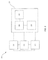
- Electromechanical brake actuator system 200 may comprise an electromechanical brake actuator 210 coupled to a derived position sensor 220.
- derived position sensor 220 may comprise a rotation sensor 222 and a controller 224.
- controller 224 may comprise a microcontroller.
- derived position sensor 220 may further comprise an output drive circuit 228 in communication with controller 224.
- rotation sensor 222 may comprise a resolver. In various embodiments, rotation sensor 222 may comprise a Hall effect sensor. In various embodiments, rotation sensor 222 may be coupled to electromechanical brake actuator 210 and configured to detect a signal from which the angular velocity of the motor shaft may be calculated.
- controller 224 may be configured to operate as a data acquisition and digital signal processing system.
- controller 224 may receive data from rotation sensor 222. Such data may be processed, stored, and analyzed by controller 224.
- controller 224 comprises an analog to digital converter, which may be configured to receive analog data from rotation sensor 222 and convert it to digital data for processing by controller 224.
- electromechanical brake actuator system 200 may further comprise an electromechanical brake actuator controller ("EBAC") 230.
- EBAC electromechanical brake actuator controller
- controller 224 comprises an output drive circuit 228.
- controller 224 may comprise an output drive circuit which comprises an analog drive circuit.
- controller 224 provides data from a digital analog converter (within controller 224) to the analog drive circuit, which may transmit the analog data to EBAC 230.
- the analog drive circuit may comprise, for example, a 4 milliamp to 20 milliamp drive circuit.
- controller 224 comprises an output drive circuit which comprises a digital drive circuit.
- controller 224 provides digital data to EBAC 230.
- the digital drive circuit may utilize a serial communication protocol, such as, for example, an RS232 or RS485 protocol.
- controller 224 may be capable of bidirectional communication with EBAC 230.
- Bidirectional communication between controller 224 and EBAC 230 may, for example, allow for built in testing to evaluate the health of EBAC 230 and various sensors, and/or to detect and correct error conditions, among other functions.
- electromechanical brake actuator system 200 may further comprise a load cell 240.
- load cell 240 may be in communication with at least one of controller 224, electromechanical brake actuator 210, and electromechanical brake actuator controller 230.
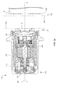
- electromechanical brake actuator 210 may comprise a first end 310, a second end 311, a derived position sensor 220, and a brake actuator housing 314.
- electromechanical brake actuator 210 may further comprise a motor shaft 306 oriented about axis of rotation 302, which extends in a linear direction from A to A'. Rotational motion of motor shaft 306 is transformed into linear motion of a ball nut 308 along axis of rotation 302. Linear translation of ball nut 308 translates ram 15 in a linear direction along axis of rotation 302.
- ram 15 may be disposed on the second end 311 of electromechanical brake actuator 210.
- derived position sensor 220 may be disposed on the first end 310 of electromechanical brake actuator 210. In various embodiments, at least a portion of derived position sensor 220 may be disposed between brake actuator housing 314 and motor shaft 306. In various embodiments, at least a portion of derived position sensor 220 may be disposed in electromechanical brake actuator 210, such that derived position sensor 220 is at least partially enclosed by a housing of electromechanical brake actuator 210. In various embodiments, at least a portion of derived position sensor 220 may be disposed on electromechanical brake actuator 210, such that derived position sensor 220 is coupled to an exterior surface of electromechanical brake actuator 210, a housing thereof, and/or a component thereof.
- FIG. 3a illustrates electromechanical brake actuator 210 in a fully retracted state, wherein ram 15 has been translated as far as possible, or substantially as far as possible, in a linear direction towards A along axis of rotation 302.
- a position of ram 15 should be understood to be a location of ram 15 along axis of rotation 302 relative to a fully retracted position 340.
- the location of ram 15 when electromechanical brake actuator 210 is in a fully retracted state may be referred to herein as the fully retracted position 340.
- FIG. 3b illustrates electromechanical brake actuator 210 in an extended state, wherein ram 15 has been translated in a positive direction and the position of ram 15 exceeds fully retracted position 340.
- an electromechanical brake actuator system may be configured to determine a position of ram 15.
- a first actual ram position may be determined by translating ram 15 a first linear distance in a positive direction from fully retracted position 340, such that the first actual ram position is at a first linear translation distance from fully retracted position 340.
- the first actual ram position may be stored by controller 224 and/or by a component external to derived position sensor 220 as a previous ram position.
- a second actual ram position may be determined by translating ram 15 a second linear distance in a positive or a negative direction from the previous ram position, such that the second actual ram position is at a second linear translation distance from fully retracted position 340.
- the second actual ram position may be calculated and/or determined by summing the first actual ram position and the second actual ram position, and/or by summing the first linear translation distance and the second linear translation distance.
- the second actual ram position may be stored by controller 224 and/or by a component external to derived position sensor 220 as a previous ram position.
- determination of the actual ram position from a previous ram position may decrease occurrences of linear translation of ram 15 to the fully retracted position 340, thereby decreasing wear on, and/or increasing cycle life of, an actuator seal 320.
- Actuator seal 320 may comprise an annular ring disposed at the second end 311 of electromechanical brake actuator 210 and configured to at least partially surround ball nut 308. Actuator seal 320 may be configured to prevent and/or minimize infiltration of water, dirt, debris, contaminants, and/or the like into brake actuator housing 314.
- determination of the actual ram position from a previous ram position may decrease linear translation of ram 15, thereby decreasing infiltration of water, dirt, debris, contaminants, and/or the like into brake actuator housing 314.
- controller 224 may comprise a processor configured to implement various logical operations in response to execution of instructions, for example, instructions stored on a non-transitory, tangible, computer-readable medium.
- non-transitory is to be understood to remove only propagating transitory signals per se from the claim scope and does not relinquish rights to all standard computer-readable media that are not only propagating transitory signals per se.
- the processor may be configured to implement smart algorithms to calculate and/or determine a position of ram 15 and/or a height of brake stack 27, (discussed below).
- the operations implemented in response to execution of instructions by controller 224 may comprise receiving a first motor shaft angular velocity at a first time (Step 401), and receiving a second motor shaft angular velocity at a second time (Step 402).
- the operations may further comprise calculating a linear translation distance (Step 403) from at least one motor shaft angular velocity and a ball screw lead angle factor.
- the ball screw lead angle factor may represent the conversion of rotational motion to linear translational motion.
- the operations may further comprise summing the linear translation distance and a previous ram position to obtain an actual ram position (Step 404).
- the operations may further comprise transmitting an output signal (Step 407) to at least one of electromechanical brake actuator controller 230 and electromechanical brake actuator 210.
- the output signal may comprise an analog and/or digital electrical signal.
- an electromechanical brake actuator system may be configured to determine a height of the brake stack.
- the height of brake stack 27 (with momentary reference to FIG. 1 ), referred to herein as a brake stack height, may comprise an axial distance from a first axial end of brake stack 27 to a second axial end of brake stack 27.
- Whether the brake stack height is less than a minimum height threshold may be determined by comparing the actual ram position to a maximum extension threshold.
- the maximum extension threshold may comprise a position of ram 15 at which, and/or greater than which, the brake stack height is less than a minimum height threshold.
- the minimum height threshold may comprise the brake stack height at which, and/or lower than which, brake disc replacement is indicated.
- the maximum extension threshold may be predetermined such that it is determined or calculated at any time prior to comparison of the maximum extension threshold and the actual ram position.
- the minimum height threshold may be predetermined such that it is determined or calculated at any time prior to comparison of the minimum height threshold and the brake stack height.
- the operations implemented in response to execution of instructions by controller 224 may further comprise comparing the actual ram position to a maximum extension position (Step 405). In various embodiments, the operations may further comprise determining that the brake stack height is less than a minimum height threshold, in response to the actual ram position exceeding the maximum extension position (Step 406). In various embodiments, the operations may further comprise transmitting an output signal (Step 407) to at least one of electromechanical brake actuator controller 230 and electromechanical brake actuator 210. In various embodiments, the output signal may communicate to the electromechanical brake actuator controller 230 that the brake stack height is less than the minimum height threshold. In various embodiments, the output signal may comprise an override command configured to override a command of the electromechanical brake actuator controller 230. In various embodiments, the override command may comprise a command to translate the ram 15 in a linear direction and/or to a position less than the maximum extension threshold.
- an electromechanical brake actuator system may be configured to determine a brake stack wear distance by subtracting a worn full load position and an unworn full load position.
- a full load position may comprise a position of ram 15, wherein ram 15 has fully translated in a positive direction towards a brake in response to a full load command.
- the full load command may cause ram 15 to exert approximately 50,042 newtons (11,250 pounds of force) on the brake stack.
- the full load command may comprise any desired load to be exerted on the brake stack.
- the full load position may be determined by a load cell and/or as a result of load cell measurements, calculations, and/or operations.
- the unworn full load position may comprise a full load position, wherein the brake stack has not been used and/or has not experienced wear.
- the unworn full load position may be predetermined such that it is determined or calculated at any time prior to subtraction of the unworn full load position and the worn full load position.
- the worn full load position may comprise a full load position, wherein the brake stack has been used and/or has experienced wear.
- the actual ram position may comprise a worn full load position.
- the worn full load position and the unworn full load position may be subtracted.
- the difference between the worn full load position and the unworn full load position may comprise the brake stack wear distance.
- the operations implemented in response to execution of instructions by controller 224 may comprise obtaining a worn full load position (Step 501).
- obtaining a worn full load position may comprise any step of method 400, including receiving a first motor shaft angular velocity at a first time (Step 401), receiving a second motor shaft angular velocity at a second time (Step 402), calculating a linear translation distance (Step 403), and/or summing the linear translation distance and a previous ram position to obtain an actual ram position (Step 404), wherein the actual ram position comprises a worn full load position.
- the operations may further comprise subtracting the worn full load position and an unworn full load position to obtain a brake stack wear distance (Step 502). In various embodiments, the operations may further comprise transmitting an output signal (Step 503) to at least one of electromechanical brake actuator controller 230 and electromechanical brake actuator 210. In various embodiments, the output signal may communicate to the electromechanical brake actuator controller 230 that the brake stack height is less than the minimum height threshold.
- an electromechanical brake actuator system may be configured to determine a running clearance position 350 by subtracting a desired running clearance 352 and a zero torque position 360.
- the desired running clearance 352 may comprise a linear distance between ram 15 and brake stack 27.
- the desired running clearance 352 may be between about 0.1905 centimeters (0.075 inches) and about 0.381 centimeters (0.150 inches).
- the desired running clearance 352 may be any distance suitable for operation of the electromechanical brake actuator system, and/or any distance suitable to eliminate or minimize drag while also minimizing electromechanical brake actuator response time, that is, an amount of time between a command being given by the electromechanical brake actuator and application of the commanded load by the ram.
- the zero torque position 360 may comprise a position of ram 15, wherein the ram 15 is not in contact or is in minimal contact with brake stack 27 and exerts no lateral compression force thereon.
- the zero torque position 360 may be determined by a load cell and/or as a result of load cell measurements, calculations, and/or operations.
- placement of the ram 15 at the zero torque position 360 may cause drag and, consequently wear, on the brake stack 27.
- drag and/or wear may be caused by friction and/or inaccurate load cell measurements, calculations, and/or operations.
- the zero torque position 360 may be obtained by the methods previously described herein. In various embodiments, the zero torque position 360 may be obtained and/or calculated from the worn full load position and a compression distance, wherein the compression distance represents a decrease in brake stack height in response to application of a full load force to the brake stack 27. In various embodiments, the zero torque position 360 may be predetermined such that it is determined or calculated at any time prior to subtraction of the desired running clearance 352 and the zero torque position 360. In various embodiments, the actual ram position may comprise a zero torque position 360.
- the zero torque position 360 and the desired running clearance 352 may be subtracted. In various embodiments, the difference between the zero torque position 360 and the desired running clearance 352 may comprise the running clearance position 350.
- the operations implemented in response to execution of instructions by controller 224 may comprise obtaining a zero torque position 360 (Step 601).
- the operations may further comprise subtracting a desired running clearance 352 and the zero torque position 360 to obtain a running clearance position 350 (Step 602).
- the operations may further comprise transmitting an output signal (Step 603) to at least one of electromechanical brake actuator controller 230 and electromechanical brake actuator 210.
- the output signal may command the electromechanical brake actuator 210 to translate the ram 15 to the running clearance position 350 (Step 604).
- the output signal may comprise communicating, to the electromechanical brake actuator controller 230, at least one of the running clearance and the running clearance position 350.
- a method 400 may comprise determining a first motor shaft angular velocity of a motor shaft at a first time (Step 401), wherein an electromechanical brake actuator 210 comprises the motor shaft and a ram 15, and is coupled to a derived position sensor 220 comprising a controller 224, a rotation sensor 222, and an output drive circuit 228.
- method 400 may further comprise determining a second motor shaft angular velocity at a second time (Step 402), calculating a linear translation distance (Step 403), and summing the linear translation distance and a previous ram position to obtain an actual ram position (Step 404).
- method 400 may further comprise comparing the actual ram position to a maximum extension position (Step 405). In various embodiments, method 400 may further comprise determining that a brake stack height is less than a minimum height threshold, in response to the actual ram position exceeding the maximum extension position (Step 406). In various embodiments, method 400 may further comprise transmitting an output signal from the output drive circuit 228 to an electromechanical brake actuator controller 230 (Step 407). In various embodiments, the transmitting may comprise communicating to an electromechanical brake actuator controller 230 the actual ram position. In various embodiments, the transmitting may comprise communicating to an electromechanical brake actuator controller 230 that the brake stack height is less than the minimum height threshold. In various embodiments, the transmitting may comprise overriding a command of an electromechanical brake actuator controller 230 to prevent and/or reverse linear translation of the ram.
- a method 500 may comprise obtaining a worn full load position (Step 501). In various embodiments, method 500 may further comprise subtracting the worn full load position and an unworn full load position to obtain a brake stack wear distance (Step 502). In various embodiments, method 500 may further comprise transmitting an output signal from the output drive circuit to an electromechanical brake actuator controller 230 (Step 503).
- a method 600 may comprise obtaining a zero torque position 360 (Step 601).
- method 600 may further comprise subtracting a desired running clearance 352 and the zero torque position 360 to obtain a running clearance position 350 (Step 602).
- method 600 may further comprise transmitting an output signal to at least one of electromechanical brake actuator controller 230 and electromechanical brake actuator (Step 603).
- the transmitting may comprise commanding the electromechanical brake actuator to translate the ram to the running clearance position.
- the output signal may comprise communicating, to the electromechanical brake actuator controller 230, at least one of the running clearance and the running clearance position 350.
- method 600 may further comprise translating a ram 15 to the running clearance position 350 (Step 604).
- references to “one embodiment”, “an embodiment”, “various embodiments”, etc. indicate that the embodiment described may include a particular feature, structure, or characteristic, but every embodiment may not necessarily include the particular feature, structure, or characteristic. Moreover, such phrases are not necessarily referring to the same embodiment. Further, when a particular feature, structure, or characteristic is described in connection with an embodiment, it is submitted that it is within the knowledge of one skilled in the art to affect such feature, structure, or characteristic in connection with other embodiments whether or not explicitly described. After reading the description, it will be apparent to one skilled in the relevant art(s) how to implement the disclosure in alternative embodiments.
Landscapes
- Engineering & Computer Science (AREA)
- General Engineering & Computer Science (AREA)
- Mechanical Engineering (AREA)
- Transportation (AREA)
- Braking Systems And Boosters (AREA)
- Braking Arrangements (AREA)
Abstract
Description
- The present disclosure relates to aircraft brake systems and methods, and more particularly, to systems and methods for detection of brake disc position and wear.
- Conventional aircraft wheel assemblies comprise brake stacks which stop the aircraft in response to the compression of rotating and stationary brake discs by either hydraulic or electromechanical actuators. Brake discs frequently comprise carbon/carbon composite material that wears with use, decreasing the thickness of the brake discs and the height of the brake stacks. Worn brake discs are replaced when wear exceeds a predetermined amount. To detect brake disc wear, aircraft wheel assemblies often utilize a wear indicator pin to determine the height of the brake stack. Other conventional aircraft wheel assemblies utilize linear variable differential transformer ("LVDT") sensors, which electronically measure the distance between the brake stack and the brake housing to calculate brake disc wear. Manually inspection of wear indicator pins is subject to human error, and LVDT sensors are associated with the addition of hardware and electronics to the aircraft wheel assembly.
- In various embodiments, the present disclosure provides an electromechanical brake actuator system comprising an electromechanical brake actuator coupled to a derived position sensor comprising a controller, a rotation sensor, and an output drive circuit. In various embodiments, the controller may comprise a microcontroller. In various embodiments, the electromechanical brake actuator may comprise a ram, and the electromechanical brake actuator system may be configured to determine a position of the ram and/or a wear state of a brake stack.
- In various embodiments, the present disclosure provides methods determining a position of a ram and/or a wear state of a brake stack. In various embodiments, a method may comprise obtaining an actual ram position by summing a linear translation distance and a previous ram position. In various embodiments, a method may comprise determining that a brake stack height is less than a minimum height threshold by comparing an actual ram position to a maximum extension position. In various embodiments, a method may comprise obtaining a brake stack wear distance by subtracting a worn full load position and an unworn full load position. In various embodiments, a method may comprise obtaining a running clearance position by subtracting a desired running clearance and a zero torque position. In various embodiments, a method may comprise transmitting an output signal, and/or translating a ram in a linear direction.
- The accompanying drawings are included to provide a further understanding of the present disclosure and are incorporated in, and constitute a part of, this specification, illustrate various embodiments, and together with the description, serve to explain the principles of the disclosure.
-
FIG. 1 illustrates a cross section view of a portion of a wheel and brake assembly in accordance with various embodiments; -
FIG. 2 illustrates a block diagram view of an electromechanical brake actuator system in accordance with various embodiments; -
FIG. 3a illustrates cross section view of a portion of an electromechanical brake actuator system in accordance with various embodiments; -
FIG. 3b illustrates a cross section view of a portion of an electromechanical brake actuator system in accordance with various embodiments; -
FIG. 4 illustrates a method of using an electromechanical brake actuator system in accordance with various embodiments; -
FIG. 5 illustrates another method of using an electromechanical brake actuator system in accordance with various embodiments; and -
FIG. 6 illustrates yet another method of using an electromechanical brake actuator system in accordance with various embodiments. - The detailed description of various embodiments herein makes reference to the accompanying drawings, which show various embodiments by way of illustration. While these various embodiments are described in sufficient detail to enable those skilled in the art to practice the disclosure, it should be understood that other embodiments may be realized and that logical, chemical, and mechanical changes may be made without departing from the spirit and scope of the disclosure. Thus, the detailed description herein is presented for purposes of illustration only and not of limitation.
- For example, the steps recited in any of the method or process descriptions may be executed in any order and are not necessarily limited to the order presented. Furthermore, any reference to singular includes plural embodiments, and any reference to more than one component or step may include a singular embodiment or step. Also, any reference to attached, fixed, connected, or the like may include permanent, removable, temporary, partial, full, and/or any other possible attachment option. Additionally, any reference to without contact (or similar phrases) may also include reduced contact or minimal contact.
- For example, in the context of the present disclosure, systems and methods may find particular use in connection with aircraft brake systems. However, various aspects of the disclosed embodiments may be adapted for optimized performance with a variety of brake systems, including automobile brake systems and various other motor vehicle brake systems. As such, numerous applications of the present disclosure may be realized.
- With reference to
FIG. 1 , a portion of a wheel andbrake system 10 is illustrated in accordance with various embodiments. Wheel andbrake system 10 may comprise, for example, abrake assembly 11. In various embodiments,brake assembly 11 may be coupled to an axle of awheel 12. For example,brake assembly 11 consists of rotors and stators that are compressed together by anelectromechanical brake actuator 36 to reduce the speed of an aircraft. In various embodiments,brake stack 27 may comprise components that interface with both the rotating rotors, and with the wheel axle throughtorque tube 16. -
Brake assembly 11 may further comprise, for example, one or moreelectromechanical brake actuators 36. For example,electromechanical brake actuators 36 may be configured such that in response to a command signal (e.g., an operator depressing a brake pedal),electromechanical brake actuators 36 laterally compressbrake stack 27 which, in turn, resists rotation ofwheel 12, thereby reducing the speed of the aircraft.Electromechanical brake actuator 36 may be coupled to or otherwise operate a motor shaft and a pressure generating device, such as, for example, aram 15. In response to a command signal,electromechanical brake actuator 36 causes the motor shaft to rotate. Rotational motion of the motor shaft may be transformed into linear motion of a ball nut. Linear translation of the ball nut towardsram 15 applies lateral compression force onbrake stack 27. - With reference to
FIG. 2 , a block diagram of an electromechanicalbrake actuator system 200 is illustrated in accordance with various embodiments. Electromechanicalbrake actuator system 200 may comprise anelectromechanical brake actuator 210 coupled to a derivedposition sensor 220. In various embodiments, derivedposition sensor 220 may comprise arotation sensor 222 and acontroller 224. In various embodiments,controller 224 may comprise a microcontroller. In various embodiments, derivedposition sensor 220 may further comprise anoutput drive circuit 228 in communication withcontroller 224. - In various embodiments,
rotation sensor 222 may comprise a resolver. In various embodiments,rotation sensor 222 may comprise a Hall effect sensor. In various embodiments,rotation sensor 222 may be coupled toelectromechanical brake actuator 210 and configured to detect a signal from which the angular velocity of the motor shaft may be calculated. - In various embodiments,
controller 224 may be configured to operate as a data acquisition and digital signal processing system. For example,controller 224 may receive data fromrotation sensor 222. Such data may be processed, stored, and analyzed bycontroller 224. In various embodiments,controller 224 comprises an analog to digital converter, which may be configured to receive analog data fromrotation sensor 222 and convert it to digital data for processing bycontroller 224. - In various embodiments, electromechanical
brake actuator system 200 may further comprise an electromechanical brake actuator controller ("EBAC") 230. After digital signal processing, data may be transmitted fromcontroller 224 toEBAC 230. In various embodiments,controller 224 comprises anoutput drive circuit 228. For example,controller 224 may comprise an output drive circuit which comprises an analog drive circuit. In such embodiments,controller 224 provides data from a digital analog converter (within controller 224) to the analog drive circuit, which may transmit the analog data toEBAC 230. The analog drive circuit may comprise, for example, a 4 milliamp to 20 milliamp drive circuit. - In various embodiments,
controller 224 comprises an output drive circuit which comprises a digital drive circuit. In such embodiments,controller 224 provides digital data toEBAC 230. For example, the digital drive circuit may utilize a serial communication protocol, such as, for example, an RS232 or RS485 protocol. Although described with reference to specific embodiments, any manner of transmitting data fromcontroller 224 toEBAC 230 is within the scope of the present disclosure. - In various embodiments,
controller 224 may be capable of bidirectional communication withEBAC 230. Bidirectional communication betweencontroller 224 andEBAC 230 may, for example, allow for built in testing to evaluate the health ofEBAC 230 and various sensors, and/or to detect and correct error conditions, among other functions. - In various embodiments, electromechanical
brake actuator system 200 may further comprise aload cell 240. In various embodiments,load cell 240 may be in communication with at least one ofcontroller 224,electromechanical brake actuator 210, and electromechanicalbrake actuator controller 230. - With reference to
FIGS. 1 ,3a , and3b , anelectromechanical brake actuator 210 is illustrated in accordance with various embodiments. In various embodiments,electromechanical brake actuator 210 may comprise afirst end 310, asecond end 311, a derivedposition sensor 220, and abrake actuator housing 314. In various embodiments,electromechanical brake actuator 210 may further comprise amotor shaft 306 oriented about axis ofrotation 302, which extends in a linear direction from A to A'. Rotational motion ofmotor shaft 306 is transformed into linear motion of aball nut 308 along axis ofrotation 302. Linear translation ofball nut 308 translatesram 15 in a linear direction along axis ofrotation 302. In various embodiments, ram 15 may be disposed on thesecond end 311 ofelectromechanical brake actuator 210. - In various embodiments, derived
position sensor 220 may be disposed on thefirst end 310 ofelectromechanical brake actuator 210. In various embodiments, at least a portion of derivedposition sensor 220 may be disposed between brakeactuator housing 314 andmotor shaft 306. In various embodiments, at least a portion of derivedposition sensor 220 may be disposed inelectromechanical brake actuator 210, such that derivedposition sensor 220 is at least partially enclosed by a housing ofelectromechanical brake actuator 210. In various embodiments, at least a portion of derivedposition sensor 220 may be disposed onelectromechanical brake actuator 210, such that derivedposition sensor 220 is coupled to an exterior surface ofelectromechanical brake actuator 210, a housing thereof, and/or a component thereof. -
FIG. 3a illustrateselectromechanical brake actuator 210 in a fully retracted state, whereinram 15 has been translated as far as possible, or substantially as far as possible, in a linear direction towards A along axis ofrotation 302. As used herein, a position ofram 15 should be understood to be a location ofram 15 along axis ofrotation 302 relative to a fully retractedposition 340. The location ofram 15 whenelectromechanical brake actuator 210 is in a fully retracted state may be referred to herein as the fully retractedposition 340. As used herein, translation ofram 15 in a linear direction towards A' may be referred to as increasing and/or positive translation, movement, and/or position; translation ofram 15 in a linear direction towards A may be referred to as decreasing and/or negative translation, movement, and/or position. Stated differently, a first position ofram 15 axially closer to A' than a second position ofram 15 is to A' may be described herein as exceeding the second position ofram 15; a second position ofram 15 axially closer to A than a first position ofram 15 is to A may be described herein as being less than the first position ofram 15.FIG. 3b illustrateselectromechanical brake actuator 210 in an extended state, whereinram 15 has been translated in a positive direction and the position ofram 15 exceeds fully retractedposition 340. - In various embodiments, an electromechanical brake actuator system may be configured to determine a position of
ram 15. In various embodiments, a first actual ram position may be determined by translating ram 15 a first linear distance in a positive direction from fully retractedposition 340, such that the first actual ram position is at a first linear translation distance from fully retractedposition 340. In various embodiments, the first actual ram position may be stored bycontroller 224 and/or by a component external to derivedposition sensor 220 as a previous ram position. In various embodiments, a second actual ram position may be determined by translating ram 15 a second linear distance in a positive or a negative direction from the previous ram position, such that the second actual ram position is at a second linear translation distance from fully retractedposition 340. In various embodiments, the second actual ram position may be calculated and/or determined by summing the first actual ram position and the second actual ram position, and/or by summing the first linear translation distance and the second linear translation distance. In various embodiments, the second actual ram position may be stored bycontroller 224 and/or by a component external to derivedposition sensor 220 as a previous ram position. - In various embodiments, determination of the actual ram position from a previous ram position may decrease occurrences of linear translation of
ram 15 to the fully retractedposition 340, thereby decreasing wear on, and/or increasing cycle life of, anactuator seal 320.Actuator seal 320 may comprise an annular ring disposed at thesecond end 311 ofelectromechanical brake actuator 210 and configured to at least partially surroundball nut 308.Actuator seal 320 may be configured to prevent and/or minimize infiltration of water, dirt, debris, contaminants, and/or the like intobrake actuator housing 314. In various embodiments, determination of the actual ram position from a previous ram position may decrease linear translation ofram 15, thereby decreasing infiltration of water, dirt, debris, contaminants, and/or the like intobrake actuator housing 314. - In various embodiments,
controller 224 may comprise a processor configured to implement various logical operations in response to execution of instructions, for example, instructions stored on a non-transitory, tangible, computer-readable medium. As used herein, the term "non-transitory" is to be understood to remove only propagating transitory signals per se from the claim scope and does not relinquish rights to all standard computer-readable media that are not only propagating transitory signals per se. Stated another way, the meaning of the term "non-transitory computer-readable medium" and "non-transitory computer-readable storage medium" should be construed to exclude only those types of transitory computer-readable media which were found in In Re Nuijten to fall outside the scope of patentable subject matter under 35 U.S.C. § 101. In various embodiments, the processor may be configured to implement smart algorithms to calculate and/or determine a position ofram 15 and/or a height ofbrake stack 27, (discussed below). - In various embodiments and with reference to
FIGs. 3a ,3b , and4 , the operations implemented in response to execution of instructions bycontroller 224 may comprise receiving a first motor shaft angular velocity at a first time (Step 401), and receiving a second motor shaft angular velocity at a second time (Step 402). In various embodiments, the operations may further comprise calculating a linear translation distance (Step 403) from at least one motor shaft angular velocity and a ball screw lead angle factor. The ball screw lead angle factor may represent the conversion of rotational motion to linear translational motion. In various embodiments, the operations may further comprise summing the linear translation distance and a previous ram position to obtain an actual ram position (Step 404). In various embodiments, the operations may further comprise transmitting an output signal (Step 407) to at least one of electromechanicalbrake actuator controller 230 andelectromechanical brake actuator 210. In various embodiments, the output signal may comprise an analog and/or digital electrical signal. - In various embodiments, an electromechanical brake actuator system may be configured to determine a height of the brake stack. The height of brake stack 27 (with momentary reference to
FIG. 1 ), referred to herein as a brake stack height, may comprise an axial distance from a first axial end ofbrake stack 27 to a second axial end ofbrake stack 27. Whether the brake stack height is less than a minimum height threshold may be determined by comparing the actual ram position to a maximum extension threshold. In various embodiments, the maximum extension threshold may comprise a position ofram 15 at which, and/or greater than which, the brake stack height is less than a minimum height threshold. In various embodiments, the minimum height threshold may comprise the brake stack height at which, and/or lower than which, brake disc replacement is indicated. In various embodiments, the maximum extension threshold may be predetermined such that it is determined or calculated at any time prior to comparison of the maximum extension threshold and the actual ram position. In various embodiments, the minimum height threshold may be predetermined such that it is determined or calculated at any time prior to comparison of the minimum height threshold and the brake stack height. - In various embodiments, the operations implemented in response to execution of instructions by
controller 224 may further comprise comparing the actual ram position to a maximum extension position (Step 405). In various embodiments, the operations may further comprise determining that the brake stack height is less than a minimum height threshold, in response to the actual ram position exceeding the maximum extension position (Step 406). In various embodiments, the operations may further comprise transmitting an output signal (Step 407) to at least one of electromechanicalbrake actuator controller 230 andelectromechanical brake actuator 210. In various embodiments, the output signal may communicate to the electromechanicalbrake actuator controller 230 that the brake stack height is less than the minimum height threshold. In various embodiments, the output signal may comprise an override command configured to override a command of the electromechanicalbrake actuator controller 230. In various embodiments, the override command may comprise a command to translate theram 15 in a linear direction and/or to a position less than the maximum extension threshold. - With reference again to
FIGs. 3a and3b , in various embodiments, an electromechanical brake actuator system may be configured to determine a brake stack wear distance by subtracting a worn full load position and an unworn full load position. As used herein, a full load position may comprise a position ofram 15, whereinram 15 has fully translated in a positive direction towards a brake in response to a full load command. In various embodiments, the full load command may causeram 15 to exert approximately 50,042 newtons (11,250 pounds of force) on the brake stack. However, in various embodiments, the full load command may comprise any desired load to be exerted on the brake stack. In various embodiments, the full load position may be determined by a load cell and/or as a result of load cell measurements, calculations, and/or operations. - In various embodiments, the unworn full load position may comprise a full load position, wherein the brake stack has not been used and/or has not experienced wear. In various embodiments, the unworn full load position may be predetermined such that it is determined or calculated at any time prior to subtraction of the unworn full load position and the worn full load position. In various embodiments, the worn full load position may comprise a full load position, wherein the brake stack has been used and/or has experienced wear. In various embodiments, the actual ram position may comprise a worn full load position.
- In various embodiments, the worn full load position and the unworn full load position may be subtracted. In various embodiments, the difference between the worn full load position and the unworn full load position may comprise the brake stack wear distance.
- In various embodiments and with reference to
FIGs. 3a ,3b , and5 , the operations implemented in response to execution of instructions bycontroller 224 may comprise obtaining a worn full load position (Step 501). In various embodiments, obtaining a worn full load position may comprise any step ofmethod 400, including receiving a first motor shaft angular velocity at a first time (Step 401), receiving a second motor shaft angular velocity at a second time (Step 402), calculating a linear translation distance (Step 403), and/or summing the linear translation distance and a previous ram position to obtain an actual ram position (Step 404), wherein the actual ram position comprises a worn full load position. In various embodiments, the operations may further comprise subtracting the worn full load position and an unworn full load position to obtain a brake stack wear distance (Step 502). In various embodiments, the operations may further comprise transmitting an output signal (Step 503) to at least one of electromechanicalbrake actuator controller 230 andelectromechanical brake actuator 210. In various embodiments, the output signal may communicate to the electromechanicalbrake actuator controller 230 that the brake stack height is less than the minimum height threshold. - With reference again to
FIGs. 3a and3b , in various embodiments, an electromechanical brake actuator system may be configured to determine a runningclearance position 350 by subtracting a desired runningclearance 352 and a zerotorque position 360. The desiredrunning clearance 352 may comprise a linear distance betweenram 15 andbrake stack 27. In various embodiments, the desired runningclearance 352 may be between about 0.1905 centimeters (0.075 inches) and about 0.381 centimeters (0.150 inches). However, the desired runningclearance 352 may be any distance suitable for operation of the electromechanical brake actuator system, and/or any distance suitable to eliminate or minimize drag while also minimizing electromechanical brake actuator response time, that is, an amount of time between a command being given by the electromechanical brake actuator and application of the commanded load by the ram. - In various embodiments, the zero
torque position 360 may comprise a position ofram 15, wherein theram 15 is not in contact or is in minimal contact withbrake stack 27 and exerts no lateral compression force thereon. In various embodiments, the zerotorque position 360 may be determined by a load cell and/or as a result of load cell measurements, calculations, and/or operations. In various embodiments, placement of theram 15 at the zerotorque position 360 may cause drag and, consequently wear, on thebrake stack 27. In various embodiments, drag and/or wear may be caused by friction and/or inaccurate load cell measurements, calculations, and/or operations. - In various embodiments, the zero
torque position 360 may be obtained by the methods previously described herein. In various embodiments, the zerotorque position 360 may be obtained and/or calculated from the worn full load position and a compression distance, wherein the compression distance represents a decrease in brake stack height in response to application of a full load force to thebrake stack 27. In various embodiments, the zerotorque position 360 may be predetermined such that it is determined or calculated at any time prior to subtraction of the desired runningclearance 352 and the zerotorque position 360. In various embodiments, the actual ram position may comprise a zerotorque position 360. - In various embodiments, the zero
torque position 360 and the desired runningclearance 352 may be subtracted. In various embodiments, the difference between the zerotorque position 360 and the desired runningclearance 352 may comprise the runningclearance position 350. - In various embodiments and with reference to
FIGs. 3a ,3b , and6 , the operations implemented in response to execution of instructions bycontroller 224 may comprise obtaining a zero torque position 360 (Step 601). In various embodiments, the operations may further comprise subtracting a desired runningclearance 352 and the zerotorque position 360 to obtain a running clearance position 350 (Step 602). In various embodiments, the operations may further comprise transmitting an output signal (Step 603) to at least one of electromechanicalbrake actuator controller 230 andelectromechanical brake actuator 210. In various embodiments, the output signal may command theelectromechanical brake actuator 210 to translate theram 15 to the running clearance position 350 (Step 604). In various embodiments, the output signal may comprise communicating, to the electromechanicalbrake actuator controller 230, at least one of the running clearance and the runningclearance position 350. - With reference again to
FIGs. 2 and4 , amethod 400 may comprise determining a first motor shaft angular velocity of a motor shaft at a first time (Step 401), wherein anelectromechanical brake actuator 210 comprises the motor shaft and aram 15, and is coupled to a derivedposition sensor 220 comprising acontroller 224, arotation sensor 222, and anoutput drive circuit 228. In various embodiments,method 400 may further comprise determining a second motor shaft angular velocity at a second time (Step 402), calculating a linear translation distance (Step 403), and summing the linear translation distance and a previous ram position to obtain an actual ram position (Step 404). - In various embodiments,
method 400 may further comprise comparing the actual ram position to a maximum extension position (Step 405). In various embodiments,method 400 may further comprise determining that a brake stack height is less than a minimum height threshold, in response to the actual ram position exceeding the maximum extension position (Step 406). In various embodiments,method 400 may further comprise transmitting an output signal from theoutput drive circuit 228 to an electromechanical brake actuator controller 230 (Step 407). In various embodiments, the transmitting may comprise communicating to an electromechanicalbrake actuator controller 230 the actual ram position. In various embodiments, the transmitting may comprise communicating to an electromechanicalbrake actuator controller 230 that the brake stack height is less than the minimum height threshold. In various embodiments, the transmitting may comprise overriding a command of an electromechanicalbrake actuator controller 230 to prevent and/or reverse linear translation of the ram. - With reference to
FIGs. 2 and5 , amethod 500 may comprise obtaining a worn full load position (Step 501). In various embodiments,method 500 may further comprise subtracting the worn full load position and an unworn full load position to obtain a brake stack wear distance (Step 502). In various embodiments,method 500 may further comprise transmitting an output signal from the output drive circuit to an electromechanical brake actuator controller 230 (Step 503). - With reference to
FIGs. 2 and6 , amethod 600 may comprise obtaining a zero torque position 360 (Step 601). In various embodiments,method 600 may further comprise subtracting a desired runningclearance 352 and the zerotorque position 360 to obtain a running clearance position 350 (Step 602). In various embodiments,method 600 may further comprise transmitting an output signal to at least one of electromechanicalbrake actuator controller 230 and electromechanical brake actuator (Step 603). In various embodiments, the transmitting may comprise commanding the electromechanical brake actuator to translate the ram to the running clearance position. In various embodiments, the output signal may comprise communicating, to the electromechanicalbrake actuator controller 230, at least one of the running clearance and the runningclearance position 350. In various embodiments,method 600 may further comprise translating aram 15 to the running clearance position 350 (Step 604). - Benefits, other advantages, and solutions to problems have been described herein with regard to specific embodiments. Furthermore, the connecting lines shown in the various figures contained herein are intended to represent exemplary functional relationships and/or physical couplings between the various elements. It should be noted that many alternative or additional functional relationships or physical connections may be present in a practical system. However, the benefits, advantages, solutions to problems, and any elements that may cause any benefit, advantage, or solution to occur or become more pronounced are not to be construed as critical, required, or essential features or elements of the disclosure. The scope of the disclosure is accordingly to be limited by nothing other than the appended claims, in which reference to an element in the singular is not intended to mean "one and only one" unless explicitly so stated, but rather "one or more." Moreover, where a phrase similar to "at least one of A, B, or C" is used in the claims, it is intended that the phrase be interpreted to mean that A alone may be present in an embodiment, B alone may be present in an embodiment, C alone may be present in an embodiment, or that any combination of the elements A, B and C may be present in a single embodiment; for example, A and B, A and C, B and C, or A and B and C. Different cross-hatching is used throughout the figures to denote different parts but not necessarily to denote the same or different materials.
- Devices and methods are provided herein. In the detailed description herein, references to "one embodiment", "an embodiment", "various embodiments", etc., indicate that the embodiment described may include a particular feature, structure, or characteristic, but every embodiment may not necessarily include the particular feature, structure, or characteristic. Moreover, such phrases are not necessarily referring to the same embodiment. Further, when a particular feature, structure, or characteristic is described in connection with an embodiment, it is submitted that it is within the knowledge of one skilled in the art to affect such feature, structure, or characteristic in connection with other embodiments whether or not explicitly described. After reading the description, it will be apparent to one skilled in the relevant art(s) how to implement the disclosure in alternative embodiments.
- Furthermore, no element, component, or method step in the present disclosure is intended to be dedicated to the public regardless of whether the element, component, or method step is explicitly recited in the claims. No claim element herein is to be construed under the provisions of 35 U.S.C. 112(f) unless the element is expressly recited using the phrase "means for." As used herein, the terms "comprises", "comprising", or any other variation thereof, are intended to cover a non-exclusive inclusion, such that a process, method, article, or apparatus that comprises a list of elements does not include only those elements but may include other elements not expressly listed or inherent to such process, method, article, or apparatus.
Claims (15)
- An electromechanical brake actuator system (200), comprising:an electromechanical brake actuator (210) comprising a ram; anda derived position sensor (220), coupled to the electromechanical brake actuator (210) and comprising a controller (224), a rotation sensor (222), and an output drive circuit (228).
- The electromechanical brake actuator system of claim 1, wherein the output drive circuit (228) provides a signal to an electromechanical brake actuator controller (230).
- The electromechanical brake actuator system of claim 2, wherein the controller (224) and the electromechanical brake actuator controller (230) are in bidirectional communication with each other.
- The electromechanical brake actuator system of claim 3, further comprising a load cell (240) in communication with at least one of the controller (224), the electromechanical brake actuator (210), and the electromechanical brake actuator controller (230).
- The electromechanical brake actuator system of any preceding claim, further comprising a tangible, non-transitory memory configured to communicate with the controller (224), the tangible, non-transitory memory having instructions stored thereon that, in response to execution by the controller (224), cause the controller to perform operations.
- The electromechanical brake actuator system of claim 5, wherein the instructions cause the controller (224) to perform the operations comprising:receiving a first motor shaft angular velocity at a first time (401);receiving a second motor shaft angular velocity at a second time (402);calculating a linear translation distance (403); andsumming the linear translation distance and a previous ram position to obtain an actual ram position (404).
- The electromechanical brake actuator system of claim 6, wherein the instructions cause the controller (224) to perform the operations further comprising:transmitting an output signal to at least one of the electromechanical brake actuator and an electromechanical brake actuator controller (603).
- The electromechanical brake actuator system of claim 7, wherein the instructions cause the controller to perform the operations further comprising:comparing the actual ram position to a maximum extension position (405); anddetermining that a brake stack height is less than a minimum height threshold, in response to the actual ram position exceeding the maximum extension position (406).
- The electromechanical brake actuator system of claim 7, wherein the actual ram position comprises a worn full load position, and wherein the instructions cause the controller to perform the operations further comprising:subtracting the worn full load position and an unworn full load position to obtain a brake stack wear distance (502).
- The electromechanical brake actuator system of claim 7, wherein the actual ram position comprises a zero torque position (360), and wherein the instructions cause the controller (224) to perform the operations further comprising:subtracting a desired running clearance and the zero torque position to obtain a running clearance position (350).
- The electromechanical brake actuator system of claim 10, wherein the instructions cause the controller (224) to perform the operations further comprising at least one of:commanding the electromechanical brake actuator to translate the ram to the running clearance position, and communicating, to an electromechanical brake actuator controller, at least one of the desired running clearance and the running clearance position.
- A method comprising:receiving, by a controller, a first motor shaft angular velocity of a motor shaft at a first time (401), wherein an electromechanical brake actuator comprises the motor shaft and a ram, and is coupled to a derived position sensor comprising the controller, a rotation sensor, and an output drive circuit;receiving, by the controller, a second motor shaft angular velocity at a second time (402);calculating, by the controller, a linear translation distance (403);summing, by the controller, the linear translation distance and a previous ram position to obtain an actual ram position (404); andtransmitting, by the controller, an output signal from the output drive circuit to an electromechanical brake actuator controller (407).
- The method of claim 12, further comprising
comparing, by the controller, the actual ram position to a maximum extension position (405); and
determining, by the controller, that a brake stack height is less than a minimum height threshold, in response to the actual ram position exceeding the maximum extension position (406). - The method of claim 12, wherein the actual ram position comprises a worn full load position, and further comprising:subtracting, by the controller, the worn full load position and an unworn full load position to obtain a brake stack wear distance (502).
- The method of claim 12, wherein the actual ram position comprises a zero torque position, and further comprising:subtracting, by the controller, a desired running clearance (352) and the zero torque position (360) to obtain a running clearance position (350); andtranslating, by the electromechanical brake actuator, the ram to the running clearance position (604).
Applications Claiming Priority (1)
| Application Number | Priority Date | Filing Date | Title |
|---|---|---|---|
| US14/689,816 US10570974B2 (en) | 2015-04-17 | 2015-04-17 | Brake position and wear detection systems and methods |
Publications (2)
| Publication Number | Publication Date |
|---|---|
| EP3081446A1 true EP3081446A1 (en) | 2016-10-19 |
| EP3081446B1 EP3081446B1 (en) | 2020-02-26 |
Family
ID=55759527
Family Applications (1)
| Application Number | Title | Priority Date | Filing Date |
|---|---|---|---|
| EP16165751.5A Active EP3081446B1 (en) | 2015-04-17 | 2016-04-18 | Brake position and wear detection system and method |
Country Status (2)
| Country | Link |
|---|---|
| US (2) | US10570974B2 (en) |
| EP (1) | EP3081446B1 (en) |
Cited By (1)
| Publication number | Priority date | Publication date | Assignee | Title |
|---|---|---|---|---|
| CN112639325A (en) * | 2018-08-31 | 2021-04-09 | 株式会社安川电机 | Brake diagnosis device and brake diagnosis system |
Families Citing this family (4)
| Publication number | Priority date | Publication date | Assignee | Title |
|---|---|---|---|---|
| US10830321B2 (en) * | 2016-02-19 | 2020-11-10 | Goodrich Corporation | Actuator ball screw for improved load sharing |
| US10106139B2 (en) | 2017-02-02 | 2018-10-23 | Goodrich Corporation | Brake systems and methods |
| US10800392B2 (en) | 2017-04-18 | 2020-10-13 | The Boeing Company | Brake health indicator systems using input and output energy |
| US10731720B2 (en) * | 2018-01-26 | 2020-08-04 | Rivian Ip Holdings, Llc | Methods, systems, and media for non-contact brake pad wear determination |
Citations (4)
| Publication number | Priority date | Publication date | Assignee | Title |
|---|---|---|---|---|
| US5522259A (en) * | 1992-11-26 | 1996-06-04 | O&K Orenstein & Koppel Ag | Process and arrangement for measuring multiple disk brake wear |
| WO1998050711A1 (en) * | 1997-05-09 | 1998-11-12 | The B.F. Goodrich Company | Electronic aircraft braking system with brake wear measurement, running clearance adjustment and plural electric motor-actuator ram assemblies |
| GB2457376A (en) * | 2008-02-14 | 2009-08-19 | Goodrich Corp | A brake wear measurement system |
| DE102012006105A1 (en) * | 2012-03-26 | 2013-09-26 | Knorr-Bremse Systeme für Nutzfahrzeuge GmbH | Sliding caliper disc brake of a motor vehicle |
Family Cites Families (23)
| Publication number | Priority date | Publication date | Assignee | Title |
|---|---|---|---|---|
| GB9411477D0 (en) * | 1994-06-08 | 1994-07-27 | Lucas Ind Plc | Brake lining wear sensing system |
| DE19536695A1 (en) | 1995-09-30 | 1997-04-03 | Teves Gmbh Alfred | System for controlling or regulating an electromechanical brake |
| DE19730094A1 (en) | 1997-07-14 | 1999-01-21 | Itt Mfg Enterprises Inc | System for controlling or regulating an electromechanical brake |
| US6095293A (en) * | 1998-02-13 | 2000-08-01 | The B. F. Goodrich Company | Aircraft brake and method with electromechanical actuator modules |
| NL1010068C2 (en) * | 1998-09-11 | 2000-03-15 | Skf Eng & Res Centre Bv | Method and device for energizing rotary-to-translators. |
| US7129658B2 (en) | 2003-10-15 | 2006-10-31 | Honeywell International Inc. | Electro-mechanical actuator braking apparatus and method using motor commutation sensor output to derive piston displacement |
| US20050258681A1 (en) | 2004-05-20 | 2005-11-24 | Delphi Technologies, Inc. | Brake with calibration and diagnostics and method and program product related thereto |
| WO2005119083A1 (en) * | 2004-06-04 | 2005-12-15 | Goodrich Corporation | Electric brake position and force sensing and control |
| GB0500305D0 (en) | 2005-01-08 | 2005-02-16 | Dunlop Aerospace Ltd | Electrically actuated aircraft brakes |
| GB0500304D0 (en) | 2005-01-08 | 2005-02-16 | Dunlop Aerospace Ltd | Electrically actuated aircraft brakes |
| EP1954538B1 (en) * | 2005-11-30 | 2014-05-21 | Goodrich Corporation | Controller for electromechanical braking system with running clearance adjustment and method |
| EP1793477B1 (en) | 2005-12-02 | 2012-02-15 | The Boeing Company | Fault-tolerant electro-mechanical actuator having a torque sensing control system |
| US20070235267A1 (en) * | 2006-04-11 | 2007-10-11 | Goodrich Corporation | Controller for electromechanical braking system with running clearance adjustment and method |
| US20080092641A1 (en) * | 2006-10-18 | 2008-04-24 | Goodrich Corporation | Wear compensated torque measurement system |
| US7847679B2 (en) * | 2007-10-26 | 2010-12-07 | Rolls-Royce Corporation | Material wear indication system |
| US8634971B2 (en) * | 2009-05-05 | 2014-01-21 | Goodrich Corporation | Brake wear control system |
| US8620550B2 (en) * | 2011-02-28 | 2013-12-31 | Deere & Company | Measuring brake wear |
| DE102013100786A1 (en) * | 2013-01-25 | 2014-07-31 | Knorr-Bremse Systeme für Nutzfahrzeuge GmbH | Disc brake with a Lüftspielüberwachungsvorrichtung and method for Lüftspielüberwachung |
| US9759626B2 (en) | 2014-08-11 | 2017-09-12 | Goodrich Corporation | System and method to adjust a force zero reference |
| EP2998607A1 (en) | 2014-09-16 | 2016-03-23 | Meritor Heavy Vehicle Braking Systems (UK) Limited | Method and system for setting a braking component running clearnace |
| US10081342B2 (en) | 2015-05-22 | 2018-09-25 | Goodrich Corporation | Systems and methods for brake actuator operation under load cell failure |
| US9610927B2 (en) | 2015-06-26 | 2017-04-04 | Goodrich Corporation | Systems and methods for electric brake force estimation tolerant to drivetrain stiction |
| US9663078B1 (en) | 2015-12-28 | 2017-05-30 | Goodrich Corporation | Systems and methods for brake actuator operation sensor error compensation |
-
2015
- 2015-04-17 US US14/689,816 patent/US10570974B2/en active Active
-
2016
- 2016-04-18 EP EP16165751.5A patent/EP3081446B1/en active Active
-
2019
- 2019-11-14 US US16/684,168 patent/US11181158B2/en active Active
Patent Citations (4)
| Publication number | Priority date | Publication date | Assignee | Title |
|---|---|---|---|---|
| US5522259A (en) * | 1992-11-26 | 1996-06-04 | O&K Orenstein & Koppel Ag | Process and arrangement for measuring multiple disk brake wear |
| WO1998050711A1 (en) * | 1997-05-09 | 1998-11-12 | The B.F. Goodrich Company | Electronic aircraft braking system with brake wear measurement, running clearance adjustment and plural electric motor-actuator ram assemblies |
| GB2457376A (en) * | 2008-02-14 | 2009-08-19 | Goodrich Corp | A brake wear measurement system |
| DE102012006105A1 (en) * | 2012-03-26 | 2013-09-26 | Knorr-Bremse Systeme für Nutzfahrzeuge GmbH | Sliding caliper disc brake of a motor vehicle |
Cited By (1)
| Publication number | Priority date | Publication date | Assignee | Title |
|---|---|---|---|---|
| CN112639325A (en) * | 2018-08-31 | 2021-04-09 | 株式会社安川电机 | Brake diagnosis device and brake diagnosis system |
Also Published As
| Publication number | Publication date |
|---|---|
| US20160305501A1 (en) | 2016-10-20 |
| EP3081446B1 (en) | 2020-02-26 |
| US11181158B2 (en) | 2021-11-23 |
| US10570974B2 (en) | 2020-02-25 |
| US20200080608A1 (en) | 2020-03-12 |
Similar Documents
| Publication | Publication Date | Title |
|---|---|---|
| US11181158B2 (en) | Brake position and wear detection systems and methods | |
| US11597363B2 (en) | Brake position system | |
| KR100697447B1 (en) | Electronic aircraft brake system with brake wear measurement mechanism, operating clearance adjustment mechanism and multiple electric motor-actuator ram assemblies | |
| EP2581623B1 (en) | Electric brake apparatus for vehicle | |
| US10100891B2 (en) | Electric brake device | |
| KR101501533B1 (en) | Motor control system for wear compensation of an electro-mechanical brake and method thereof | |
| US9610927B2 (en) | Systems and methods for electric brake force estimation tolerant to drivetrain stiction | |
| US10422663B2 (en) | Displacement sensor | |
| US9533666B2 (en) | Brake force measurement techniques | |
| US10473554B2 (en) | Gearbox torque measurement system | |
| US20200094506A1 (en) | Method for calibrating electric press | |
| CN103562589B (en) | Brake for wind power plant | |
| US10493962B2 (en) | Brake position system | |
| US20250327499A1 (en) | Electro-mechanical brake apparatus and vehicle | |
| EP3009317B1 (en) | Electric brake device | |
| US7469593B2 (en) | Piezo-electric force sensor and method | |
| JP7178483B2 (en) | electric brake device | |
| JP4215856B2 (en) | Electric brake device | |
| WO2023243266A1 (en) | Electric brake device | |
| CN221173688U (en) | Rotation shaft torque sensor | |
| EP4711216A1 (en) | Force determination unit for determining a force feedback, electro-mechanical actuator assembly and method for determining a force feedback | |
| CN120435408A (en) | Braking unit arranged on a wheel of a motor vehicle | |
| KR20140023472A (en) | Electronic parking brake and method for measuring braking power using the same |
Legal Events
| Date | Code | Title | Description |
|---|---|---|---|
| PUAI | Public reference made under article 153(3) epc to a published international application that has entered the european phase |
Free format text: ORIGINAL CODE: 0009012 |
|
| AK | Designated contracting states |
Kind code of ref document: A1 Designated state(s): AL AT BE BG CH CY CZ DE DK EE ES FI FR GB GR HR HU IE IS IT LI LT LU LV MC MK MT NL NO PL PT RO RS SE SI SK SM TR |
|
| AX | Request for extension of the european patent |
Extension state: BA ME |
|
| STAA | Information on the status of an ep patent application or granted ep patent |
Free format text: STATUS: REQUEST FOR EXAMINATION WAS MADE |
|
| 17P | Request for examination filed |
Effective date: 20170419 |
|
| RBV | Designated contracting states (corrected) |
Designated state(s): AL AT BE BG CH CY CZ DE DK EE ES FI FR GB GR HR HU IE IS IT LI LT LU LV MC MK MT NL NO PL PT RO RS SE SI SK SM TR |
|
| STAA | Information on the status of an ep patent application or granted ep patent |
Free format text: STATUS: EXAMINATION IS IN PROGRESS |
|
| 17Q | First examination report despatched |
Effective date: 20171222 |
|
| GRAP | Despatch of communication of intention to grant a patent |
Free format text: ORIGINAL CODE: EPIDOSNIGR1 |
|
| STAA | Information on the status of an ep patent application or granted ep patent |
Free format text: STATUS: GRANT OF PATENT IS INTENDED |
|
| INTG | Intention to grant announced |
Effective date: 20190913 |
|
| GRAS | Grant fee paid |
Free format text: ORIGINAL CODE: EPIDOSNIGR3 |
|
| GRAA | (expected) grant |
Free format text: ORIGINAL CODE: 0009210 |
|
| STAA | Information on the status of an ep patent application or granted ep patent |
Free format text: STATUS: THE PATENT HAS BEEN GRANTED |
|
| AK | Designated contracting states |
Kind code of ref document: B1 Designated state(s): AL AT BE BG CH CY CZ DE DK EE ES FI FR GB GR HR HU IE IS IT LI LT LU LV MC MK MT NL NO PL PT RO RS SE SI SK SM TR |
|
| REG | Reference to a national code |
Ref country code: GB Ref legal event code: FG4D |
|
| REG | Reference to a national code |
Ref country code: CH Ref legal event code: EP |
|
| REG | Reference to a national code |
Ref country code: DE Ref legal event code: R096 Ref document number: 602016030402 Country of ref document: DE |
|
| REG | Reference to a national code |
Ref country code: AT Ref legal event code: REF Ref document number: 1237264 Country of ref document: AT Kind code of ref document: T Effective date: 20200315 |
|
| REG | Reference to a national code |
Ref country code: IE Ref legal event code: FG4D |
|
| PG25 | Lapsed in a contracting state [announced via postgrant information from national office to epo] |
Ref country code: RS Free format text: LAPSE BECAUSE OF FAILURE TO SUBMIT A TRANSLATION OF THE DESCRIPTION OR TO PAY THE FEE WITHIN THE PRESCRIBED TIME-LIMIT Effective date: 20200226 Ref country code: FI Free format text: LAPSE BECAUSE OF FAILURE TO SUBMIT A TRANSLATION OF THE DESCRIPTION OR TO PAY THE FEE WITHIN THE PRESCRIBED TIME-LIMIT Effective date: 20200226 Ref country code: NO Free format text: LAPSE BECAUSE OF FAILURE TO SUBMIT A TRANSLATION OF THE DESCRIPTION OR TO PAY THE FEE WITHIN THE PRESCRIBED TIME-LIMIT Effective date: 20200526 |
|
| REG | Reference to a national code |
Ref country code: NL Ref legal event code: MP Effective date: 20200226 |
|
| REG | Reference to a national code |
Ref country code: LT Ref legal event code: MG4D |
|
| PG25 | Lapsed in a contracting state [announced via postgrant information from national office to epo] |
Ref country code: LV Free format text: LAPSE BECAUSE OF FAILURE TO SUBMIT A TRANSLATION OF THE DESCRIPTION OR TO PAY THE FEE WITHIN THE PRESCRIBED TIME-LIMIT Effective date: 20200226 Ref country code: SE Free format text: LAPSE BECAUSE OF FAILURE TO SUBMIT A TRANSLATION OF THE DESCRIPTION OR TO PAY THE FEE WITHIN THE PRESCRIBED TIME-LIMIT Effective date: 20200226 Ref country code: BG Free format text: LAPSE BECAUSE OF FAILURE TO SUBMIT A TRANSLATION OF THE DESCRIPTION OR TO PAY THE FEE WITHIN THE PRESCRIBED TIME-LIMIT Effective date: 20200526 Ref country code: IS Free format text: LAPSE BECAUSE OF FAILURE TO SUBMIT A TRANSLATION OF THE DESCRIPTION OR TO PAY THE FEE WITHIN THE PRESCRIBED TIME-LIMIT Effective date: 20200626 Ref country code: GR Free format text: LAPSE BECAUSE OF FAILURE TO SUBMIT A TRANSLATION OF THE DESCRIPTION OR TO PAY THE FEE WITHIN THE PRESCRIBED TIME-LIMIT Effective date: 20200527 Ref country code: HR Free format text: LAPSE BECAUSE OF FAILURE TO SUBMIT A TRANSLATION OF THE DESCRIPTION OR TO PAY THE FEE WITHIN THE PRESCRIBED TIME-LIMIT Effective date: 20200226 |
|
| PG25 | Lapsed in a contracting state [announced via postgrant information from national office to epo] |
Ref country code: NL Free format text: LAPSE BECAUSE OF FAILURE TO SUBMIT A TRANSLATION OF THE DESCRIPTION OR TO PAY THE FEE WITHIN THE PRESCRIBED TIME-LIMIT Effective date: 20200226 |
|
| PG25 | Lapsed in a contracting state [announced via postgrant information from national office to epo] |
Ref country code: SK Free format text: LAPSE BECAUSE OF FAILURE TO SUBMIT A TRANSLATION OF THE DESCRIPTION OR TO PAY THE FEE WITHIN THE PRESCRIBED TIME-LIMIT Effective date: 20200226 Ref country code: RO Free format text: LAPSE BECAUSE OF FAILURE TO SUBMIT A TRANSLATION OF THE DESCRIPTION OR TO PAY THE FEE WITHIN THE PRESCRIBED TIME-LIMIT Effective date: 20200226 Ref country code: EE Free format text: LAPSE BECAUSE OF FAILURE TO SUBMIT A TRANSLATION OF THE DESCRIPTION OR TO PAY THE FEE WITHIN THE PRESCRIBED TIME-LIMIT Effective date: 20200226 Ref country code: SM Free format text: LAPSE BECAUSE OF FAILURE TO SUBMIT A TRANSLATION OF THE DESCRIPTION OR TO PAY THE FEE WITHIN THE PRESCRIBED TIME-LIMIT Effective date: 20200226 Ref country code: DK Free format text: LAPSE BECAUSE OF FAILURE TO SUBMIT A TRANSLATION OF THE DESCRIPTION OR TO PAY THE FEE WITHIN THE PRESCRIBED TIME-LIMIT Effective date: 20200226 Ref country code: LT Free format text: LAPSE BECAUSE OF FAILURE TO SUBMIT A TRANSLATION OF THE DESCRIPTION OR TO PAY THE FEE WITHIN THE PRESCRIBED TIME-LIMIT Effective date: 20200226 Ref country code: CZ Free format text: LAPSE BECAUSE OF FAILURE TO SUBMIT A TRANSLATION OF THE DESCRIPTION OR TO PAY THE FEE WITHIN THE PRESCRIBED TIME-LIMIT Effective date: 20200226 Ref country code: ES Free format text: LAPSE BECAUSE OF FAILURE TO SUBMIT A TRANSLATION OF THE DESCRIPTION OR TO PAY THE FEE WITHIN THE PRESCRIBED TIME-LIMIT Effective date: 20200226 Ref country code: PT Free format text: LAPSE BECAUSE OF FAILURE TO SUBMIT A TRANSLATION OF THE DESCRIPTION OR TO PAY THE FEE WITHIN THE PRESCRIBED TIME-LIMIT Effective date: 20200719 |
|
| REG | Reference to a national code |
Ref country code: DE Ref legal event code: R119 Ref document number: 602016030402 Country of ref document: DE |
|
| REG | Reference to a national code |
Ref country code: AT Ref legal event code: MK05 Ref document number: 1237264 Country of ref document: AT Kind code of ref document: T Effective date: 20200226 |
|
| PG25 | Lapsed in a contracting state [announced via postgrant information from national office to epo] |
Ref country code: MC Free format text: LAPSE BECAUSE OF FAILURE TO SUBMIT A TRANSLATION OF THE DESCRIPTION OR TO PAY THE FEE WITHIN THE PRESCRIBED TIME-LIMIT Effective date: 20200226 |
|
| REG | Reference to a national code |
Ref country code: CH Ref legal event code: PL |
|
| PLBE | No opposition filed within time limit |
Free format text: ORIGINAL CODE: 0009261 |
|
| STAA | Information on the status of an ep patent application or granted ep patent |
Free format text: STATUS: NO OPPOSITION FILED WITHIN TIME LIMIT |
|
| PG25 | Lapsed in a contracting state [announced via postgrant information from national office to epo] |
Ref country code: LU Free format text: LAPSE BECAUSE OF NON-PAYMENT OF DUE FEES Effective date: 20200418 Ref country code: AT Free format text: LAPSE BECAUSE OF FAILURE TO SUBMIT A TRANSLATION OF THE DESCRIPTION OR TO PAY THE FEE WITHIN THE PRESCRIBED TIME-LIMIT Effective date: 20200226 Ref country code: IT Free format text: LAPSE BECAUSE OF FAILURE TO SUBMIT A TRANSLATION OF THE DESCRIPTION OR TO PAY THE FEE WITHIN THE PRESCRIBED TIME-LIMIT Effective date: 20200226 Ref country code: DE Free format text: LAPSE BECAUSE OF NON-PAYMENT OF DUE FEES Effective date: 20201103 Ref country code: LI Free format text: LAPSE BECAUSE OF NON-PAYMENT OF DUE FEES Effective date: 20200430 Ref country code: CH Free format text: LAPSE BECAUSE OF NON-PAYMENT OF DUE FEES Effective date: 20200430 |
|
| 26N | No opposition filed |
Effective date: 20201127 |
|
| REG | Reference to a national code |
Ref country code: BE Ref legal event code: MM Effective date: 20200430 |
|
| PG25 | Lapsed in a contracting state [announced via postgrant information from national office to epo] |
Ref country code: SI Free format text: LAPSE BECAUSE OF FAILURE TO SUBMIT A TRANSLATION OF THE DESCRIPTION OR TO PAY THE FEE WITHIN THE PRESCRIBED TIME-LIMIT Effective date: 20200226 Ref country code: PL Free format text: LAPSE BECAUSE OF FAILURE TO SUBMIT A TRANSLATION OF THE DESCRIPTION OR TO PAY THE FEE WITHIN THE PRESCRIBED TIME-LIMIT Effective date: 20200226 Ref country code: BE Free format text: LAPSE BECAUSE OF NON-PAYMENT OF DUE FEES Effective date: 20200430 |
|
| PG25 | Lapsed in a contracting state [announced via postgrant information from national office to epo] |
Ref country code: IE Free format text: LAPSE BECAUSE OF NON-PAYMENT OF DUE FEES Effective date: 20200418 |
|
| PG25 | Lapsed in a contracting state [announced via postgrant information from national office to epo] |
Ref country code: TR Free format text: LAPSE BECAUSE OF FAILURE TO SUBMIT A TRANSLATION OF THE DESCRIPTION OR TO PAY THE FEE WITHIN THE PRESCRIBED TIME-LIMIT Effective date: 20200226 Ref country code: MT Free format text: LAPSE BECAUSE OF FAILURE TO SUBMIT A TRANSLATION OF THE DESCRIPTION OR TO PAY THE FEE WITHIN THE PRESCRIBED TIME-LIMIT Effective date: 20200226 Ref country code: CY Free format text: LAPSE BECAUSE OF FAILURE TO SUBMIT A TRANSLATION OF THE DESCRIPTION OR TO PAY THE FEE WITHIN THE PRESCRIBED TIME-LIMIT Effective date: 20200226 |
|
| PG25 | Lapsed in a contracting state [announced via postgrant information from national office to epo] |
Ref country code: MK Free format text: LAPSE BECAUSE OF FAILURE TO SUBMIT A TRANSLATION OF THE DESCRIPTION OR TO PAY THE FEE WITHIN THE PRESCRIBED TIME-LIMIT Effective date: 20200226 Ref country code: AL Free format text: LAPSE BECAUSE OF FAILURE TO SUBMIT A TRANSLATION OF THE DESCRIPTION OR TO PAY THE FEE WITHIN THE PRESCRIBED TIME-LIMIT Effective date: 20200226 |
|
| P01 | Opt-out of the competence of the unified patent court (upc) registered |
Effective date: 20230522 |
|
| PGFP | Annual fee paid to national office [announced via postgrant information from national office to epo] |
Ref country code: GB Payment date: 20260319 Year of fee payment: 11 |
|
| PGFP | Annual fee paid to national office [announced via postgrant information from national office to epo] |
Ref country code: FR Payment date: 20260320 Year of fee payment: 11 |