EP3081400A1 - Tire for winter - Google Patents
Tire for winter Download PDFInfo
- Publication number
- EP3081400A1 EP3081400A1 EP14875074.8A EP14875074A EP3081400A1 EP 3081400 A1 EP3081400 A1 EP 3081400A1 EP 14875074 A EP14875074 A EP 14875074A EP 3081400 A1 EP3081400 A1 EP 3081400A1
- Authority
- EP
- European Patent Office
- Prior art keywords
- tire
- edge
- vertex
- triangular block
- stud pin
- Prior art date
- Legal status (The legal status is an assumption and is not a legal conclusion. Google has not performed a legal analysis and makes no representation as to the accuracy of the status listed.)
- Granted
Links
- 230000000694 effects Effects 0.000 description 17
- 238000012360 testing method Methods 0.000 description 9
- 238000004891 communication Methods 0.000 description 2
- 238000010008 shearing Methods 0.000 description 2
- 229920001875 Ebonite Polymers 0.000 description 1
- 230000001154 acute effect Effects 0.000 description 1
- 238000013461 design Methods 0.000 description 1
- 238000011161 development Methods 0.000 description 1
- 238000006073 displacement reaction Methods 0.000 description 1
- 238000000926 separation method Methods 0.000 description 1
- 238000010998 test method Methods 0.000 description 1
Images


Classifications
-
- B—PERFORMING OPERATIONS; TRANSPORTING
- B60—VEHICLES IN GENERAL
- B60C—VEHICLE TYRES; TYRE INFLATION; TYRE CHANGING; CONNECTING VALVES TO INFLATABLE ELASTIC BODIES IN GENERAL; DEVICES OR ARRANGEMENTS RELATED TO TYRES
- B60C11/00—Tyre tread bands; Tread patterns; Anti-skid inserts
- B60C11/14—Anti-skid inserts, e.g. vulcanised into the tread band
- B60C11/16—Anti-skid inserts, e.g. vulcanised into the tread band of plug form, e.g. made from metal, textile
- B60C11/1625—Arrangements thereof in the tread patterns, e.g. irregular
-
- B—PERFORMING OPERATIONS; TRANSPORTING
- B60—VEHICLES IN GENERAL
- B60C—VEHICLE TYRES; TYRE INFLATION; TYRE CHANGING; CONNECTING VALVES TO INFLATABLE ELASTIC BODIES IN GENERAL; DEVICES OR ARRANGEMENTS RELATED TO TYRES
- B60C11/00—Tyre tread bands; Tread patterns; Anti-skid inserts
- B60C11/03—Tread patterns
- B60C11/0302—Tread patterns directional pattern, i.e. with main rolling direction
-
- B—PERFORMING OPERATIONS; TRANSPORTING
- B60—VEHICLES IN GENERAL
- B60C—VEHICLE TYRES; TYRE INFLATION; TYRE CHANGING; CONNECTING VALVES TO INFLATABLE ELASTIC BODIES IN GENERAL; DEVICES OR ARRANGEMENTS RELATED TO TYRES
- B60C11/00—Tyre tread bands; Tread patterns; Anti-skid inserts
- B60C11/03—Tread patterns
- B60C11/11—Tread patterns in which the raised area of the pattern consists only of isolated elements, e.g. blocks
-
- B—PERFORMING OPERATIONS; TRANSPORTING
- B60—VEHICLES IN GENERAL
- B60C—VEHICLE TYRES; TYRE INFLATION; TYRE CHANGING; CONNECTING VALVES TO INFLATABLE ELASTIC BODIES IN GENERAL; DEVICES OR ARRANGEMENTS RELATED TO TYRES
- B60C11/00—Tyre tread bands; Tread patterns; Anti-skid inserts
- B60C11/03—Tread patterns
- B60C11/12—Tread patterns characterised by the use of narrow slits or incisions, e.g. sipes
- B60C11/1204—Tread patterns characterised by the use of narrow slits or incisions, e.g. sipes with special shape of the sipe
- B60C11/1218—Three-dimensional shape with regard to depth and extending direction
-
- B—PERFORMING OPERATIONS; TRANSPORTING
- B60—VEHICLES IN GENERAL
- B60C—VEHICLE TYRES; TYRE INFLATION; TYRE CHANGING; CONNECTING VALVES TO INFLATABLE ELASTIC BODIES IN GENERAL; DEVICES OR ARRANGEMENTS RELATED TO TYRES
- B60C11/00—Tyre tread bands; Tread patterns; Anti-skid inserts
- B60C11/03—Tread patterns
- B60C11/12—Tread patterns characterised by the use of narrow slits or incisions, e.g. sipes
- B60C11/1236—Tread patterns characterised by the use of narrow slits or incisions, e.g. sipes with special arrangements in the tread pattern
-
- B—PERFORMING OPERATIONS; TRANSPORTING
- B60—VEHICLES IN GENERAL
- B60C—VEHICLE TYRES; TYRE INFLATION; TYRE CHANGING; CONNECTING VALVES TO INFLATABLE ELASTIC BODIES IN GENERAL; DEVICES OR ARRANGEMENTS RELATED TO TYRES
- B60C11/00—Tyre tread bands; Tread patterns; Anti-skid inserts
- B60C11/03—Tread patterns
- B60C11/13—Tread patterns characterised by the groove cross-section, e.g. for buttressing or preventing stone-trapping
- B60C11/1369—Tie bars for linking block elements and bridging the groove
-
- B—PERFORMING OPERATIONS; TRANSPORTING
- B60—VEHICLES IN GENERAL
- B60C—VEHICLE TYRES; TYRE INFLATION; TYRE CHANGING; CONNECTING VALVES TO INFLATABLE ELASTIC BODIES IN GENERAL; DEVICES OR ARRANGEMENTS RELATED TO TYRES
- B60C11/00—Tyre tread bands; Tread patterns; Anti-skid inserts
- B60C11/14—Anti-skid inserts, e.g. vulcanised into the tread band
- B60C11/16—Anti-skid inserts, e.g. vulcanised into the tread band of plug form, e.g. made from metal, textile
-
- B—PERFORMING OPERATIONS; TRANSPORTING
- B60—VEHICLES IN GENERAL
- B60C—VEHICLE TYRES; TYRE INFLATION; TYRE CHANGING; CONNECTING VALVES TO INFLATABLE ELASTIC BODIES IN GENERAL; DEVICES OR ARRANGEMENTS RELATED TO TYRES
- B60C11/00—Tyre tread bands; Tread patterns; Anti-skid inserts
- B60C11/03—Tread patterns
- B60C2011/0337—Tread patterns characterised by particular design features of the pattern
- B60C2011/0339—Grooves
- B60C2011/0358—Lateral grooves, i.e. having an angle of 45 to 90 degees to the equatorial plane
- B60C2011/0362—Shallow grooves, i.e. having a depth of less than 50% of other grooves
-
- B—PERFORMING OPERATIONS; TRANSPORTING
- B60—VEHICLES IN GENERAL
- B60C—VEHICLE TYRES; TYRE INFLATION; TYRE CHANGING; CONNECTING VALVES TO INFLATABLE ELASTIC BODIES IN GENERAL; DEVICES OR ARRANGEMENTS RELATED TO TYRES
- B60C11/00—Tyre tread bands; Tread patterns; Anti-skid inserts
- B60C11/03—Tread patterns
- B60C2011/0337—Tread patterns characterised by particular design features of the pattern
- B60C2011/0339—Grooves
- B60C2011/0374—Slant grooves, i.e. having an angle of about 5 to 35 degrees to the equatorial plane
-
- B—PERFORMING OPERATIONS; TRANSPORTING
- B60—VEHICLES IN GENERAL
- B60C—VEHICLE TYRES; TYRE INFLATION; TYRE CHANGING; CONNECTING VALVES TO INFLATABLE ELASTIC BODIES IN GENERAL; DEVICES OR ARRANGEMENTS RELATED TO TYRES
- B60C11/00—Tyre tread bands; Tread patterns; Anti-skid inserts
- B60C11/03—Tread patterns
- B60C11/12—Tread patterns characterised by the use of narrow slits or incisions, e.g. sipes
- B60C11/1204—Tread patterns characterised by the use of narrow slits or incisions, e.g. sipes with special shape of the sipe
- B60C2011/1213—Tread patterns characterised by the use of narrow slits or incisions, e.g. sipes with special shape of the sipe sinusoidal or zigzag at the tread surface
Definitions
- the present invention relates to a tire for winter having an excellent on-ice performance.
- Patent Document 1 Japanese Unexamined Patent Application Publication No. 2010-149599
- the tapered portion is provided with a sipe.
- the tread portion is separated into a plurality of blocks including a triangular block having a substantially triangular ground contact surface.
- the ground contact surface of the triangular block includes a first vertex having a smallest interior angle and a first edge facing the first vertex.
- the center of the stud pin or the hole is located on the side of the first edge of the triangular block.
- the standard wheel rim is a wheel rim approved for each tire by standards organizations on which the tire is based, wherein the standard wheel rim is the "standard rim” specified in JATMA, the "Design Rim” in TRA, and the “Measuring Rim” in ETRTO, for example.
- the standard tire load is a tire load approved for each tire by standards organizations in which the tire is based, wherein the standard tire load is the "maximum load capacity" in JATMA, the maximum value given in the above-mentioned table in TRA, the "Load Capacity" in ETRTO, for example.
- FIG. 2 illustrates a cross-sectional view of FIG. 1 taken along a line A-A of FIG. 1 .
- a groove depth d1 of the inclined main grooves 10 and a groove depth d2 of the longitudinal grooves 15, for example, are preferably set in a range of from 3.0 to 10.0 mm.
- each triangular block 30 includes a first edge 41, a second edge 42 and a third edge 43.
- the rigidity of the main portion 35 of the triangular block improves.
- the stud pin and the triangular block 30 securely chip into the road surface on-ice traveling, and thus on-ice performance can be improved.
- a portion around the first vertex 31 apart from the stud pin can maintain its flexibility, it can follow the road surface.
- an edge of the tapered portion 36 can exert an excellent edge effect. Accordingly, both of edge effect and spike effect can be obtained in good balance.
- reduction of frictional force at when the tire starts to slip on driving on ice may be gentle to improve steering stability on ice.
- the interior angle ⁇ 3 of the third vertex 33 is preferably not less than 40 degrees, more preferably not less than 45 degrees, and preferably not more than 60 degrees, more preferably not more than 55 degrees.
- the third vertex 33 can prevent damage occurring from the main portion 35, and the block can chip into the road surface to improve on-ice performance.
- the second edge 42 extends in the circumferential direction of the tire in a straight shape or an arc shape.
- a length L2 of the second edge 42 is preferably not less than 2.2 times, more preferably not less than 2.3 times, and preferably not more than 2.5 times, more preferably not more than 2.4 times of the length L1 of the first edge 41.
- the second edge 42 may offer an excellent edge effect to the axial direction of the tire.
- the tapered portion 36 is provided with a plurality of zigzag sipes 48.
- a space t1 between adjacent sipes 48 and 48 is preferably set in a range of from 3.5 to 4.8 mm, for example.
- the sipes 48 may further improve edge effect of the tapered portion 36.
- FIG. 6 illustrates an enlarged perspective view of a cross-section of one of the sipes 48 of FIG. 3 .
- the sipe 48 is preferably configured as so-called "Miura-ori" structure.
- the sipe 48 with the Miura-ori structure includes a zigzag opening 48e.
- the Miura-ori structured sipe 48 extends in a depth direction while oscillating in a longitudinal direction of the sipe and keeping its zigzag shape.
- Such a sipe 48 can enhance the rigidity of the block by being engaged uneven sipe walls 48w with each other, and thus steering stability can be improved.
- the region 49 preferably is raised in a height of from 0.5 to 2.0 mm from the ground contact surface. Such a region 49 can prevent damage from occurring around the hole 8 effectively.
- the land ratio Lr of the tread portion 2 is preferably in a range of not less than 55%, more preferably not less than 60%, and preferably not more than 75%, more preferably not more than 70%.
- the land ratio is defined as the ratio Sb /Sa of a net total ground contact area Sb to an imaginary total ground contact area Sa obtained by being filled up all the grooves and sipes between the tread edges Te and Te.
Landscapes
- Engineering & Computer Science (AREA)
- Mechanical Engineering (AREA)
- Tires In General (AREA)
Abstract
Description
- The present invention relates to a tire for winter having an excellent on-ice performance.
- The following
Patent Document 1 has proposed a tire for winter including a tread portion provided with blocks with a stud pin. As the stud pin chips into icy road surface during traveling on ice, the tire for winter may exert an excellent on-ice performance. - In order to prevent removal of the stud pin, the blocks of the tread portion are formed of a rubber having a relatively hard hardness. Furthermore, in general, blocks having a hole for installing a stud pin have a substantially rectangular ground contact surface in order to suppress deformation of the block at the time of traveling. When a stud pin is press-fitted into the hole, the rigidity around the hole of the block further improves.
- Such a block for winter tire tends to deform less at the time of grounding, and thus an edge of the block cannot be in contact with the ground sufficiently. Accordingly, edge effect may be reduced. Furthermore, on ice traveling, frictional force tends to decrease suddenly at when the tire starts to slip, and thus steering stability on ice may be deteriorated.
- Patent Document 1: Japanese Unexamined Patent Application Publication No.
2010-149599 - The present invention has been made in view of circumstances described above, and has a major object to provide a tire for winter that exhibits an excellent on-ice performance.
- The present invention provides a tire for winter including a tread portion being provided with a stud pin or a hole for a stud pin, the tread portion being separated into a plurality of blocks including a triangular block having a substantially triangular ground contact surface, the ground contact surface of the triangular block including a first vertex having a smallest interior angle and a first edge facing the first vertex, and the center of the stud pin or the hole being located on the side of the first edge of the triangular block.
- In the tire for winter according to the invention, it is preferable that the ground contact surface of the triangular block includes a main portion defined between the first edge and an imaginary middle line that extends in parallel with the first edge and that divides a length between the first edge and the first vertex in a direction perpendicular to the first edge into equal parts and a tapered portion between the imaginary middle line and the first vertex, and the center of the stud pin or the hole is located on the main portion.
- In the tire for winter according to the invention, it is preferable that the triangular block is provided on a tire equator.
- In the tire for winter according to the invention, it is preferable that the interior angle of the first vertex is of from 20 to 40 degrees.
- In the tire for winter according to the invention, it is preferable that the tread portion is provided with a groove adjacent to the first edge, and the groove is provided with a tie-bar in which a groove bottom raises.
- In the tire for winter according to the invention, it is preferable that the tapered portion is provided with a sipe.
- In the tire for winter according to the invention, it is preferable that the ground contact surface of the triangular block includes a second vertex having a greatest interior angle, and the interior angle of the second vertex is an obtuse angle.
- The tire for winter according to the present invention includes a tread portion provided with a stud pin or a hole for a stud pin. The stud pin can scratch or chip into ice surfaces to offer an excellent on-ice performance.
- The tread portion is separated into a plurality of blocks including a triangular block having a substantially triangular ground contact surface. The ground contact surface of the triangular block includes a first vertex having a smallest interior angle and a first edge facing the first vertex. The center of the stud pin or the hole is located on the side of the first edge of the triangular block.
- When a stud pin is press-fitted into the hole, the rigidity around the first edge of the triangular block improves. Thus, the stud pin and the triangular block securely chip into the road surface on-ice traveling, and thus on-ice performance can be improved. Meanwhile, since a portion around the first vertex apart from the stud pin can maintain its flexibility, it can follow the road surface. Thus, the edge around the first vertex can exert an excellent edge effect. Accordingly, both of edge effect and spike effect can be obtained in good balance. Furthermore, reduction of frictional force at when the tire starts to slip on driving on ice may be gentle to improve steering stability on ice.
- As described above, the tire for winter according to the present invention can exhibit an excellent on-ice performance.
-
-
FIG. 1 is a development view of a tread portion of a pneumatic tire according to the present embodiment. -
FIG. 2 is a cross-sectional view ofFIG. 1 taken along a line A-A. -
FIG. 3 is an enlarged view of a triangular block ofFIG. 1 . -
FIG. 4 is a cross-sectional view of a first vertex ofFIG. 3 taken along a line B-B. -
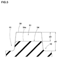
FIG. 5 is a cross-sectional view of a groove adjacent to a first edge inFIG. 3 taken long a line C-C. -
FIG. 6 is an enlarged perspective view of a cross-section of a sipe. -
- 2
- Tread portion
- 8
- Hole
- 20
- Block
- 30
- Triangular block
- 31
- First vertex
- 41
- First edge
- Hereinafter, an embodiment of the present invention will be described with reference to the accompanying drawings.
FIG. 1 illustrates atread portion 2 of atire 1 for winter according to the present embodiment (hereinafter, referred to as "tire"). The tire is used with a stud pin that is provided on thetread portion 2. InFIG. 1 , the stud pin is omitted. Thetire 1 according to the present embodiment, for example, is suitably used as a winter tire for passenger cars. - As illustrated in
FIG. 1 , thetire 1 according to the present invention includes atread portion 2 provided with a directional tread pattern having a designated rotational direction R. The rotational direction R is displayed on a sidewall using a character or mark, for example. - As the directional pattern, the
tread portion 2 is provided with a plurality of inclinedmain grooves 10 and a plurality oflongitudinal grooves 15. - The inclined
main grooves 10, for example, extend from tread edges Te toward the tire equator C with an inclination, and terminate beyond the tire equator C. In this embodiment, the inclinedmain grooves 10 extend in an arc shape, for example. - The tread edges Te are defined as axially outermost edges of the ground contacting patch which occurs under a standard condition of the
tire 1 with a standard tire load when the camber angle of the tire is zero. The standard condition is such that the tire is mounted on a standard rim with a standard pressure but is loaded with no tire load. Unless otherwise noted, dimensions of respective portions of the tire are values measured under the standard condition. - The standard wheel rim is a wheel rim approved for each tire by standards organizations on which the tire is based, wherein the standard wheel rim is the "standard rim" specified in JATMA, the "Design Rim" in TRA, and the "Measuring Rim" in ETRTO, for example.
- The standard pressure is a standard pressure approved for each tire by standards organizations on which the tire is based, wherein the standard pressure is the "maximum air pressure" in JATMA, the maximum pressure given in the "Tire Load Limits at Various Cold Inflation Pressures" table in TRA, and the "Inflation Pressure" in ETRTO, for example.
- The standard tire load is a tire load approved for each tire by standards organizations in which the tire is based, wherein the standard tire load is the "maximum load capacity" in JATMA, the maximum value given in the above-mentioned table in TRA, the "Load Capacity" in ETRTO, for example.
- The inclined
main grooves 10, for example, include first inclinedmain grooves 11 and second inclinedmain grooves 12. The first inclinedmain grooves 11 and the second inclinedmain grooves 12 are arranged alternately in the circumferential direction of the tire. The first inclinedmain grooves 11 extend from a first tread edge Te1, which is one of the tread edges, toward the tire equator C, and terminate in communication with second inclinedmain grooves 12. The second inclinedmain grooves 12 extend from a second tread edge Te2, which is the other one of tread edges, toward the tire equator C, and terminate in communication with first inclinedmain grooves 11. - The
longitudinal grooves 15, for example, extend in the circumferential direction of the tire with an inclination direction same as the inclinedmain grooves 10. Eachlongitudinal groove 15 connects a pair of circumferentially adjacent inclinedmain grooves - The
longitudinal grooves 15, for example, include inner firstlongitudinal grooves 16 and inner secondlongitudinal grooves 17 arranged on both sides of the tire equator. The inner firstlongitudinal grooves 16 are arranged on afirst land portion 6A between the tire equator C and the first tread edge Te1. The inner secondlongitudinal grooves 17 are arranged on asecond land portion 6B between the tire equator C and the second tread edge Te2. - A groove width W1 of the inclined
main grooves 10 and a groove width W2 of thelongitudinal grooves 15 are preferably set in a range of from 3.0% to 8.5% of a tread width TW. Thus, the tire can compress snow by the grooves effectively to generate large snow-shearing force when traveling on snow. The tread width TW is an axial distance between the first tread edge Te1 and the second tread edge Te2 under the standard condition. -
FIG. 2 illustrates a cross-sectional view ofFIG. 1 taken along a line A-A ofFIG. 1 . As illustrated inFIG. 2 , a groove depth d1 of the inclinedmain grooves 10 and a groove depth d2 of thelongitudinal grooves 15, for example, are preferably set in a range of from 3.0 to 10.0 mm. - As illustrated in
FIG. 1 , thetread portion 2 is separated into a plurality ofblocks 20 by the above grooves. Theblocks 20 include atriangular block 30 having a substantially triangular ground contact surface. In this description, a substantially triangular shape includes one that each side oftriangular block 30 is not straight (e.g., a curve line). Furthermore, a substantially triangular shape includes one that one of vertexes of thetriangular block 30 is rounded. - In this embodiment, the
triangular block 30, for example, includes firsttriangular blocks 30A and secondtriangular blocks 30B. - Each of the first
triangular blocks 30A is defined by one of the first inclinedmain grooves 11, one of the second inclinedmain grooves 12 and one of the inner firstlongitudinal grooves 16. Each of the secondtriangular blocks 30B is defined by one of the first inclinedmain grooves 11, one of the second inclinedmain grooves 12 and one of the inner secondlongitudinal grooves 17. The firsttriangular block 30A and the second triangular blocks 30B are alternately arranged in the circumferential direction of the tire. -
FIG. 3 illustrates an enlarged view of triangular blocks 30. As illustrated inFIG. 3 , theground contact surface 39 of eachtriangular block 30 includes afirst vertex 31, asecond vertex 32 and athird vertex 33. - The
first vertex 31 has the smallest interior angle θ1. For example, the interior angle θ1 of thefirst vertex 31 is an acute angle of less than 60 degrees. Thesecond vertex 32 has the greatest interior angle θ2. Thethird vertex 33 has an interior angle θ3 greater than the interior angle θ1 of thefirst vertex 31 and smaller than the interior angle θ2 of thesecond vertex 32. In this embodiment, theground contact surface 39 of eachtriangular block 30 is formed as a substantially scalene triangle having sides different from one another. - The
ground contact surface 39 of eachtriangular block 30 includes afirst edge 41, asecond edge 42 and athird edge 43. - The
first edge 41 faces thefirst vertex 31. Thesecond edge 42 faces thesecond vertex 32. Thethird edge 43 faces thethird vertex 33. - The
ground contact surface 39 of eachtriangular block 30 includes amain portion 35 and a taperedportion 36. - The
main portion 35 is a portion defined between thefirst edge 41 and an imaginarymiddle line 38. The taperedportion 36 is a portion defined between the imaginarymiddle line 38 and thefirst vertex 31. The imaginarymiddle line 38 extends in parallel with thefirst edge 41 and divides a length Lh between thefirst edge 41 and thefirst vertex 31 into equal parts. The length Lh is a length measured perpendicular to thefirst edge 41. - One of the triangular blocks 30 is provided with a
hole 8 for a stud pin. Thecenter 9 of thehole 8 is located on the side of thefirst edge 41 of thetriangular block 30. In this embodiment, as a preferred embodiment, thecenter 9 of thehole 8 is located on themain portion 35. - When a stud pin is press-fitted into the
hole 8, the rigidity of themain portion 35 of the triangular block improves. Thus, the stud pin and thetriangular block 30 securely chip into the road surface on-ice traveling, and thus on-ice performance can be improved. Meanwhile, since a portion around thefirst vertex 31 apart from the stud pin can maintain its flexibility, it can follow the road surface. Thus, an edge of the taperedportion 36 can exert an excellent edge effect. Accordingly, both of edge effect and spike effect can be obtained in good balance. Furthermore, reduction of frictional force at when the tire starts to slip on driving on ice may be gentle to improve steering stability on ice. - In order to further improve the above effects, the
triangular block 30 is preferably arranged on the tire equator C. Thus, large ground contact pressure acts on thetriangular block 30, and thus an excellent on-ice performance can be achieved. - Preferably, the
first vertex 31, for example, protrudes toward an opposite direction to the rotational direction R of thetire 1. Thus, themain portion 35 of thetriangular block 30 comes into contact with the ground before the taperedportion 36. This would prevent damage occurring from the taperedportion 36. - The interior angle θ1 of the
first vertex 31 is preferably not less than 20 degrees, more preferably not less than 25 degrees, and preferably not more than 40 degrees, more preferably not more than 35 degrees. Thefirst vertex 31 can exert an excellent edge effect while preventing damage occurring from the taperedportion 36. -
FIG. 4 illustrates a cross-sectional view of the first vertex ofFIG. 3 taken along a line B-B. As illustrated inFIG. 4 , thefirst vertex 31 is preferably provided with a chamferedportion 47 on acorner portion 45 formed between theground contact surface 39 and ablock sidewall 44, wherein the chamferedportion 47 is such that thecorner portion 45 is obliquely removed. The chamferedportion 47 may prevent damage occurring from the taperedportion 36. - As illustrated in
FIG. 3 , thesecond vertex 32, for example, protrudes axially outwardly with respect to the tire equator C. Thesecond vertex 32 may improve axial rigidity of thetriangular block 30, and thus steering stability of the tire can be improved. - The interior angle θ2 of the
second vertex 32 is preferably an obtuse angle. The interior angle θ2 of thesecond vertex 32 is preferably not less than 105 degrees, more preferably not less than 110 degrees, and preferably not more than 120 degrees, more preferably not more than 115 degrees. This would improve axial rigidity of thetriangular block 30. - Preferably, the
third vertex 33 protrudes toward the rotational direction R of the tire. With this, themain portion 35 can come into contact with the ground before the taperedportion 36. Accordingly, themain portion 35 and the stud pin can firmly chip into the road surface, and thus an excellent on-ice performance can be offered. - The interior angle θ3 of the
third vertex 33 is preferably not less than 40 degrees, more preferably not less than 45 degrees, and preferably not more than 60 degrees, more preferably not more than 55 degrees. Thethird vertex 33 can prevent damage occurring from themain portion 35, and the block can chip into the road surface to improve on-ice performance. - The
first edge 41, for example, extends in a straight shape. The length L1 of thefirst edge 41 is preferably in a range of not less than 0.45 times more preferably not less than 0.50 times, and preferably not more than 0.65 times, more preferably not more than 0.60 times of the length Lh from thefirst edge 41 to thefirst vertex 31. Due to thefirst edge 41, rigidity of themain portion 35 can be maintained with an excellent edge effect. -
FIG. 5 illustrates a cross-sectional view of agroove 51 adjacent to one offirst edges 41 inFIG. 3 taken long a line C-C. As illustrated inFIG. 5 , thegroove 51 adjacent to one offirst edges 41 is preferably provided with a tie-bar 54 in which a groove bottom raises. The tie-bar 54 may enhance rigidity between circumferentially adjacent triangular blocks 30 and 30 to improve steering stability on ice. A tie-bar depth d3 from theground contact surface 39 to anouter surface 54s of the tie-bar 54 is preferably not less than 0.4 times, more preferably not less than 0.45 times, and preferably not more than 0.6 times, more preferably not more than 0.55 times of the groove depth d1 of the inclinedmain grooves 10. - As illustrated in
FIG. 3 , thesecond edge 42, for example, extends in the circumferential direction of the tire in a straight shape or an arc shape. A length L2 of thesecond edge 42 is preferably not less than 2.2 times, more preferably not less than 2.3 times, and preferably not more than 2.5 times, more preferably not more than 2.4 times of the length L1 of thefirst edge 41. Thesecond edge 42 may offer an excellent edge effect to the axial direction of the tire. - Preferably, the
second edge 42, for example, is provided with arecess 46 extending toward a centroid of theground contact surface 39 of thetriangular block 30. Therecess 46 according to the embodiment, for example, is provided in the vicinity of the middle of thesecond edge 42. Therecess 46 promotes the flexibility of the taperedportion 36, and thus an excellent edge effect can be offered. - The
third edge 43, for example, extends across the tire equator C with an inclination with respect to the circumferential direction of the tire. Thethird edge 43, for example, is configured as a straight shape or a smooth arc shape. The length L3 of thethird edge 43 is preferably not less than 1.8 times, more preferably not less than 1.9 times, and preferably not more than 2.1 times, more preferably not more than 2.0 times of the length L1 of thefirst edge 41. Thethird edge 43 may exert edge effect in both of circumferential and axial directions in good balance. - Preferably, the tapered
portion 36 is provided with a plurality ofzigzag sipes 48. A space t1 betweenadjacent sipes sipes 48 may further improve edge effect of the taperedportion 36. -
FIG. 6 illustrates an enlarged perspective view of a cross-section of one of thesipes 48 ofFIG. 3 . As illustrated inFIG. 6 , thesipe 48 is preferably configured as so-called "Miura-ori" structure. Thesipe 48 with the Miura-ori structure includes azigzag opening 48e. Furthermore, the Miura-ori structuredsipe 48 extends in a depth direction while oscillating in a longitudinal direction of the sipe and keeping its zigzag shape. Such asipe 48 can enhance the rigidity of the block by being engageduneven sipe walls 48w with each other, and thus steering stability can be improved. - As illustrated in
FIG. 3 , at least onesipe 48 may be provided on themain portion 35. In this embodiment, a plurality of sipes are provided between thehole 8 and thethird vertex 33. - An
annular region 49 for fixing a stud pin is preferably provided around thehole 8, wherein theregion 49 is not provided with any sipes. Preferably, theregion 49 has a diameter r1 in a range of from 5 to 10 mm from thecenter 9 of thehole 8, for example. Theregion 49 can improve holding force of thehole 8 for a stud pin (hereinafter, referred as "pin-holding property") effectively. - As illustrated in
FIG. 2 , theregion 49 preferably is raised in a height of from 0.5 to 2.0 mm from the ground contact surface. Such aregion 49 can prevent damage from occurring around thehole 8 effectively. - As illustrated in
FIG. 1 , as for the tire for winter, the land ratio Lr of thetread portion 2 is preferably in a range of not less than 55%, more preferably not less than 60%, and preferably not more than 75%, more preferably not more than 70%. Thus, large snow-shearing force can be obtained while maintaining sufficient rigidity of thetread portion 2. In this description, the land ratio is defined as the ratio Sb /Sa of a net total ground contact area Sb to an imaginary total ground contact area Sa obtained by being filled up all the grooves and sipes between the tread edges Te and Te. - As illustrated in
FIG. 2 , atread rubber 2G, for example, is configured as a double-layer structure including acap rubber layer 4 exposed at the outer surface and abase rubber layer 5 disposed inside thecap rubber layer 4. Thecap rubber layer 4 is preferably made of rubber having JIS-A hardness smaller than that of thebase rubber layer 5. Such acap rubber layer 4 may improve edge effect of each block. Thebase rubber layer 5 can maintain sufficient rigidity of thetread portion 2 to improve steering stability. The term JIS-A hardness herein refers to a durometer type-A hardness of rubber measured at 23 degrees C. environments in compliance with JIS-K6253. - The JIS-A hardness Hc of the
cap rubber layer 4 is preferably in a range of not less than 46 degrees, more preferably not less than 50 degrees, and preferably not more than 58 degrees, more preferably not more than 54 degrees. Such acap rubber layer 4 would suppress uneven wear of thetread portion 2 while improving edge effect. - The JIS-A hardness Hb of the
base rubber layer 5 is preferably in a range of not less than 58 degrees, more preferably not less than 62 degrees, and preferably not more than 68 degrees, more preferably not more than 64 degrees. Such abase rubber layer 5 would increase rigidity of thetread portion 2 while preventing a separation from thecap rubber layer 4. - Preferably, a
bottom portion 8d of thehole 8 for a stud pin is located in thebase rubber layer 5. This configuration would improve the pin-holding property when the stud pin is inserted in thehole 8 since the flange of the stud pin is held by thebase rubber layer 5 made of a hard rubber composition. - While the particularly preferable embodiments in accordance with the present invention have been described in detail, the present invention is not limited to the illustrated embodiments, but can be modified and carried out in various aspects.
- Winter tires for passenger cars 205/60R16 having a basic tread pattern illustrated in
-
FIG. 1 were manufactured based on the detail shown in Table 1. As for a tire of Ref. 1, a winter tire with stud pins that are installed on only blocks having a substantially rectangular ground contact surface was also manufactured. Then, on-ice performance, steering stability on ice and pin-holding property of each test tire were tested. The common specification and the test method are as follows. - Rim: 16x6.5
- Tire inner pressure: Front 240 kPa, Rear 220 kPa
- Test vehicle: Front wheel drive car with displacement of 2,000 cc
- Tire installing location: All the wheels
- Grip performance on ice:
- Grip performance on ice of the test vehicle with test tires was evaluated by the driver's feeling. The results are indicated in Table 1 using a score based on the result of Ref. 1 being 100. The larger the value, the better the grip performance on ice is.
- Steering stability on ice:
- Steering stability on ice of the test vehicle with test tires was evaluated by the driver's feeling. The results are indicated in Table 1 using a score based on the result of Ref. 1 being 100. The larger the value, the better the steering stability on ice is.
- Pin-holding property:
- After the test vehicle traveled a certain distance, the number of stud pins that were remained on blocks was counted. The results are indicated in Table 1 using an index based on the result of Ref. 1 being 100. The larger the value, the better the performance is.
- The test results are shown in Table 1.


- From the test results, it is confirmed that the winter tires according to the embodiment exert an excellent on-ice performance.
Claims (7)
- A tire for winter comprising:a tread portion being provided with a stud pin or a hole for a stud pin, the tread portion being separated into a plurality of blocks comprising a triangular block having a substantially triangular ground contact surface;the ground contact surface of the triangular block comprising a first vertex having a smallest interior angle and a first edge facing the first vertex; andthe center of the stud pin or the hole being located on the side of the first edge of the triangular block.
- The tire for winter according to claim 1,
wherein the ground contact surface of the triangular block comprises
a main portion defined between the first edge and an imaginary middle line that extends in parallel with the first edge and that divides a length between the first edge and the first vertex in a direction perpendicular to the first edge into equal parts and
a tapered portion between the imaginary middle line and the first vertex, and
the center of the stud pin or the hole is located on the main portion. - The tire for winter according to claim 1 or 2,
wherein the triangular block is provided on a tire equator. - The tire for winter according to any one of claims 1 to 3,
wherein the interior angle of the first vertex is of from 20 to 40 degrees. - The tire for winter according to any one of claims 1 to 4,
wherein the tread portion is provided with a groove adjacent to the first edge, and the groove is provided with a tie-bar in which a groove bottom raises. - The tire for winter according to claim 2,
wherein the tapered portion is provided with a sipe. - The tire for winter according to any one of claims 1 to 6,
wherein the ground contact surface of the triangular block comprises a second vertex having a greatest interior angle, and the interior angle of the second vertex is an obtuse angle.
Applications Claiming Priority (2)
| Application Number | Priority Date | Filing Date | Title |
|---|---|---|---|
| JP2013271790A JP5860451B2 (en) | 2013-12-27 | 2013-12-27 | Winter tires |
| PCT/JP2014/082851 WO2015098547A1 (en) | 2013-12-27 | 2014-12-11 | Tire for winter |
Publications (3)
| Publication Number | Publication Date |
|---|---|
| EP3081400A1 true EP3081400A1 (en) | 2016-10-19 |
| EP3081400A4 EP3081400A4 (en) | 2017-10-11 |
| EP3081400B1 EP3081400B1 (en) | 2020-04-15 |
Family
ID=53478411
Family Applications (1)
| Application Number | Title | Priority Date | Filing Date |
|---|---|---|---|
| EP14875074.8A Active EP3081400B1 (en) | 2013-12-27 | 2014-12-11 | Tire for winter |
Country Status (5)
| Country | Link |
|---|---|
| EP (1) | EP3081400B1 (en) |
| JP (1) | JP5860451B2 (en) |
| CN (1) | CN105813859B (en) |
| RU (1) | RU2663960C2 (en) |
| WO (1) | WO2015098547A1 (en) |
Cited By (6)
| Publication number | Priority date | Publication date | Assignee | Title |
|---|---|---|---|---|
| EP3392064A1 (en) * | 2017-04-17 | 2018-10-24 | Sumitomo Rubber Industries, Ltd. | Pneumatic tire |
| US10232672B2 (en) * | 2015-05-26 | 2019-03-19 | Sumitomo Rubber Industries, Ltd. | Winter tire |
| WO2020012279A1 (en) * | 2018-07-13 | 2020-01-16 | Pirelli Tyre S.P.A. | Tyre for vehicle wheels |
| EP3698984A1 (en) * | 2019-02-20 | 2020-08-26 | Sumitomo Rubber Industries, Ltd. | Studdable tire |
| WO2020157606A3 (en) * | 2019-01-28 | 2020-11-05 | Pirelli Tyre S.P.A. | Car tyre |
| EP4000962A1 (en) * | 2020-11-17 | 2022-05-25 | Sumitomo Rubber Industries, Ltd. | Tire |
Families Citing this family (8)
| Publication number | Priority date | Publication date | Assignee | Title |
|---|---|---|---|---|
| JP6360459B2 (en) * | 2015-05-26 | 2018-07-18 | 住友ゴム工業株式会社 | Winter tires |
| JP6579906B2 (en) * | 2015-10-16 | 2019-09-25 | 株式会社ブリヂストン | tire |
| JP6834190B2 (en) | 2016-06-27 | 2021-02-24 | 住友ゴム工業株式会社 | tire |
| WO2019123277A1 (en) * | 2017-12-22 | 2019-06-27 | Bridgestone Europe Nv/Sa | Tread for a pneumatic tyre |
| JP7040064B2 (en) * | 2018-01-31 | 2022-03-23 | 住友ゴム工業株式会社 | Motorcycle tires for rough terrain |
| JP2020006753A (en) * | 2018-07-04 | 2020-01-16 | 株式会社ブリヂストン | tire |
| CN109501527B (en) * | 2018-10-26 | 2021-01-01 | 安徽佳通乘用子午线轮胎有限公司 | Snow tire with tread pattern structure |
| JP7200734B2 (en) * | 2019-02-19 | 2023-01-10 | 住友ゴム工業株式会社 | tire |
Family Cites Families (10)
| Publication number | Priority date | Publication date | Assignee | Title |
|---|---|---|---|---|
| DE10007464A1 (en) * | 2000-02-18 | 2001-09-06 | Continental Ag | Vehicle tires with spikes, method for producing a vehicle tire with spikes |
| JP3945635B2 (en) * | 2002-03-14 | 2007-07-18 | 横浜ゴム株式会社 | Pneumatic tire |
| JP2007050718A (en) * | 2005-08-15 | 2007-03-01 | Yokohama Rubber Co Ltd:The | Pneumatic stud tire |
| JP4677027B2 (en) * | 2008-12-24 | 2011-04-27 | 住友ゴム工業株式会社 | Pneumatic tire and spike tire |
| RU2492064C2 (en) * | 2009-02-24 | 2013-09-10 | Бриджстоун Корпорейшн | Snow tire |
| CN201511766U (en) * | 2009-03-20 | 2010-06-23 | 广州橡森轮胎有限公司 | Nail-embedded winter tire |
| EP2243638B1 (en) * | 2009-04-24 | 2017-11-08 | Pirelli Tyre S.p.A. | Method for designing a studded tyre and according studded tyre |
| DE102009044767A1 (en) * | 2009-12-03 | 2011-06-09 | Continental Reifen Deutschland Gmbh | Vehicle tires |
| JP5480868B2 (en) * | 2011-10-07 | 2014-04-23 | 住友ゴム工業株式会社 | Pneumatic tire |
| JP5432967B2 (en) * | 2011-10-27 | 2014-03-05 | 住友ゴム工業株式会社 | Pneumatic tire |
-
2013
- 2013-12-27 JP JP2013271790A patent/JP5860451B2/en active Active
-
2014
- 2014-12-11 CN CN201480066879.8A patent/CN105813859B/en active Active
- 2014-12-11 RU RU2016126432A patent/RU2663960C2/en active
- 2014-12-11 EP EP14875074.8A patent/EP3081400B1/en active Active
- 2014-12-11 WO PCT/JP2014/082851 patent/WO2015098547A1/en active Application Filing
Cited By (6)
| Publication number | Priority date | Publication date | Assignee | Title |
|---|---|---|---|---|
| US10232672B2 (en) * | 2015-05-26 | 2019-03-19 | Sumitomo Rubber Industries, Ltd. | Winter tire |
| EP3392064A1 (en) * | 2017-04-17 | 2018-10-24 | Sumitomo Rubber Industries, Ltd. | Pneumatic tire |
| WO2020012279A1 (en) * | 2018-07-13 | 2020-01-16 | Pirelli Tyre S.P.A. | Tyre for vehicle wheels |
| WO2020157606A3 (en) * | 2019-01-28 | 2020-11-05 | Pirelli Tyre S.P.A. | Car tyre |
| EP3698984A1 (en) * | 2019-02-20 | 2020-08-26 | Sumitomo Rubber Industries, Ltd. | Studdable tire |
| EP4000962A1 (en) * | 2020-11-17 | 2022-05-25 | Sumitomo Rubber Industries, Ltd. | Tire |
Also Published As
| Publication number | Publication date |
|---|---|
| RU2016126432A (en) | 2018-02-01 |
| JP5860451B2 (en) | 2016-02-16 |
| CN105813859A (en) | 2016-07-27 |
| EP3081400A4 (en) | 2017-10-11 |
| CN105813859B (en) | 2017-12-15 |
| RU2663960C2 (en) | 2018-08-13 |
| EP3081400B1 (en) | 2020-04-15 |
| RU2016126432A3 (en) | 2018-06-14 |
| WO2015098547A1 (en) | 2015-07-02 |
| JP2015123937A (en) | 2015-07-06 |
Similar Documents
| Publication | Publication Date | Title |
|---|---|---|
| EP3081400B1 (en) | Tire for winter | |
| EP3098089B1 (en) | Winter tire | |
| US10086655B2 (en) | Pneumatic tire | |
| US10836215B2 (en) | Tire | |
| US10266013B2 (en) | Pneumatic tire | |
| EP3162594B1 (en) | Pneumatic tire | |
| EP3000622B1 (en) | Pneumatic tire | |
| US10232672B2 (en) | Winter tire | |
| US10668775B2 (en) | Tire | |
| CN110406327B (en) | Tyre | |
| EP3444131B1 (en) | Tire | |
| US10889150B2 (en) | Pneumatic tire | |
| EP3335910A1 (en) | Tire | |
| EP3078505B1 (en) | Tire for winter | |
| JP5876901B2 (en) | Winter tires | |
| CN108437703B (en) | Tyre for vehicle wheels | |
| JP5876866B2 (en) | Winter tires | |
| JP7310434B2 (en) | tire | |
| JP7494592B2 (en) | tire | |
| JP2023124165A (en) | tire |
Legal Events
| Date | Code | Title | Description |
|---|---|---|---|
| PUAI | Public reference made under article 153(3) epc to a published international application that has entered the european phase |
Free format text: ORIGINAL CODE: 0009012 |
|
| 17P | Request for examination filed |
Effective date: 20160711 |
|
| AK | Designated contracting states |
Kind code of ref document: A1 Designated state(s): AL AT BE BG CH CY CZ DE DK EE ES FI FR GB GR HR HU IE IS IT LI LT LU LV MC MK MT NL NO PL PT RO RS SE SI SK SM TR |
|
| AX | Request for extension of the european patent |
Extension state: BA ME |
|
| DAX | Request for extension of the european patent (deleted) | ||
| A4 | Supplementary search report drawn up and despatched |
Effective date: 20170913 |
|
| RIC1 | Information provided on ipc code assigned before grant |
Ipc: B60C 11/12 20060101ALI20170907BHEP Ipc: B60C 11/03 20060101ALI20170907BHEP Ipc: B60C 11/13 20060101ALI20170907BHEP Ipc: B60C 11/16 20060101AFI20170907BHEP Ipc: B60C 11/11 20060101ALI20170907BHEP |
|
| RIC1 | Information provided on ipc code assigned before grant |
Ipc: B60C 11/11 20060101ALI20190923BHEP Ipc: B60C 11/12 20060101ALI20190923BHEP Ipc: B60C 11/16 20060101AFI20190923BHEP Ipc: B60C 11/13 20060101ALI20190923BHEP Ipc: B60C 11/03 20060101ALI20190923BHEP |
|
| GRAP | Despatch of communication of intention to grant a patent |
Free format text: ORIGINAL CODE: EPIDOSNIGR1 |
|
| STAA | Information on the status of an ep patent application or granted ep patent |
Free format text: STATUS: GRANT OF PATENT IS INTENDED |
|
| INTG | Intention to grant announced |
Effective date: 20191127 |
|
| GRAS | Grant fee paid |
Free format text: ORIGINAL CODE: EPIDOSNIGR3 |
|
| GRAA | (expected) grant |
Free format text: ORIGINAL CODE: 0009210 |
|
| STAA | Information on the status of an ep patent application or granted ep patent |
Free format text: STATUS: THE PATENT HAS BEEN GRANTED |
|
| AK | Designated contracting states |
Kind code of ref document: B1 Designated state(s): AL AT BE BG CH CY CZ DE DK EE ES FI FR GB GR HR HU IE IS IT LI LT LU LV MC MK MT NL NO PL PT RO RS SE SI SK SM TR |
|
| REG | Reference to a national code |
Ref country code: CH Ref legal event code: EP |
|
| REG | Reference to a national code |
Ref country code: DE Ref legal event code: R096 Ref document number: 602014063942 Country of ref document: DE |
|
| REG | Reference to a national code |
Ref country code: IE Ref legal event code: FG4D |
|
| REG | Reference to a national code |
Ref country code: AT Ref legal event code: REF Ref document number: 1256840 Country of ref document: AT Kind code of ref document: T Effective date: 20200515 |
|
| REG | Reference to a national code |
Ref country code: FI Ref legal event code: FGE |
|
| REG | Reference to a national code |
Ref country code: NL Ref legal event code: MP Effective date: 20200415 |
|
| REG | Reference to a national code |
Ref country code: LT Ref legal event code: MG4D |
|
| PG25 | Lapsed in a contracting state [announced via postgrant information from national office to epo] |
Ref country code: LT Free format text: LAPSE BECAUSE OF FAILURE TO SUBMIT A TRANSLATION OF THE DESCRIPTION OR TO PAY THE FEE WITHIN THE PRESCRIBED TIME-LIMIT Effective date: 20200415 Ref country code: NL Free format text: LAPSE BECAUSE OF FAILURE TO SUBMIT A TRANSLATION OF THE DESCRIPTION OR TO PAY THE FEE WITHIN THE PRESCRIBED TIME-LIMIT Effective date: 20200415 Ref country code: PT Free format text: LAPSE BECAUSE OF FAILURE TO SUBMIT A TRANSLATION OF THE DESCRIPTION OR TO PAY THE FEE WITHIN THE PRESCRIBED TIME-LIMIT Effective date: 20200817 Ref country code: SE Free format text: LAPSE BECAUSE OF FAILURE TO SUBMIT A TRANSLATION OF THE DESCRIPTION OR TO PAY THE FEE WITHIN THE PRESCRIBED TIME-LIMIT Effective date: 20200415 Ref country code: GR Free format text: LAPSE BECAUSE OF FAILURE TO SUBMIT A TRANSLATION OF THE DESCRIPTION OR TO PAY THE FEE WITHIN THE PRESCRIBED TIME-LIMIT Effective date: 20200716 Ref country code: IS Free format text: LAPSE BECAUSE OF FAILURE TO SUBMIT A TRANSLATION OF THE DESCRIPTION OR TO PAY THE FEE WITHIN THE PRESCRIBED TIME-LIMIT Effective date: 20200815 Ref country code: NO Free format text: LAPSE BECAUSE OF FAILURE TO SUBMIT A TRANSLATION OF THE DESCRIPTION OR TO PAY THE FEE WITHIN THE PRESCRIBED TIME-LIMIT Effective date: 20200715 |
|
| REG | Reference to a national code |
Ref country code: AT Ref legal event code: MK05 Ref document number: 1256840 Country of ref document: AT Kind code of ref document: T Effective date: 20200415 |
|
| PG25 | Lapsed in a contracting state [announced via postgrant information from national office to epo] |
Ref country code: RS Free format text: LAPSE BECAUSE OF FAILURE TO SUBMIT A TRANSLATION OF THE DESCRIPTION OR TO PAY THE FEE WITHIN THE PRESCRIBED TIME-LIMIT Effective date: 20200415 Ref country code: BG Free format text: LAPSE BECAUSE OF FAILURE TO SUBMIT A TRANSLATION OF THE DESCRIPTION OR TO PAY THE FEE WITHIN THE PRESCRIBED TIME-LIMIT Effective date: 20200715 Ref country code: LV Free format text: LAPSE BECAUSE OF FAILURE TO SUBMIT A TRANSLATION OF THE DESCRIPTION OR TO PAY THE FEE WITHIN THE PRESCRIBED TIME-LIMIT Effective date: 20200415 Ref country code: HR Free format text: LAPSE BECAUSE OF FAILURE TO SUBMIT A TRANSLATION OF THE DESCRIPTION OR TO PAY THE FEE WITHIN THE PRESCRIBED TIME-LIMIT Effective date: 20200415 |
|
| PG25 | Lapsed in a contracting state [announced via postgrant information from national office to epo] |
Ref country code: AL Free format text: LAPSE BECAUSE OF FAILURE TO SUBMIT A TRANSLATION OF THE DESCRIPTION OR TO PAY THE FEE WITHIN THE PRESCRIBED TIME-LIMIT Effective date: 20200415 |
|
| REG | Reference to a national code |
Ref country code: DE Ref legal event code: R097 Ref document number: 602014063942 Country of ref document: DE |
|
| PG25 | Lapsed in a contracting state [announced via postgrant information from national office to epo] |
Ref country code: CZ Free format text: LAPSE BECAUSE OF FAILURE TO SUBMIT A TRANSLATION OF THE DESCRIPTION OR TO PAY THE FEE WITHIN THE PRESCRIBED TIME-LIMIT Effective date: 20200415 Ref country code: RO Free format text: LAPSE BECAUSE OF FAILURE TO SUBMIT A TRANSLATION OF THE DESCRIPTION OR TO PAY THE FEE WITHIN THE PRESCRIBED TIME-LIMIT Effective date: 20200415 Ref country code: DK Free format text: LAPSE BECAUSE OF FAILURE TO SUBMIT A TRANSLATION OF THE DESCRIPTION OR TO PAY THE FEE WITHIN THE PRESCRIBED TIME-LIMIT Effective date: 20200415 Ref country code: IT Free format text: LAPSE BECAUSE OF FAILURE TO SUBMIT A TRANSLATION OF THE DESCRIPTION OR TO PAY THE FEE WITHIN THE PRESCRIBED TIME-LIMIT Effective date: 20200415 Ref country code: SM Free format text: LAPSE BECAUSE OF FAILURE TO SUBMIT A TRANSLATION OF THE DESCRIPTION OR TO PAY THE FEE WITHIN THE PRESCRIBED TIME-LIMIT Effective date: 20200415 Ref country code: AT Free format text: LAPSE BECAUSE OF FAILURE TO SUBMIT A TRANSLATION OF THE DESCRIPTION OR TO PAY THE FEE WITHIN THE PRESCRIBED TIME-LIMIT Effective date: 20200415 Ref country code: EE Free format text: LAPSE BECAUSE OF FAILURE TO SUBMIT A TRANSLATION OF THE DESCRIPTION OR TO PAY THE FEE WITHIN THE PRESCRIBED TIME-LIMIT Effective date: 20200415 Ref country code: ES Free format text: LAPSE BECAUSE OF FAILURE TO SUBMIT A TRANSLATION OF THE DESCRIPTION OR TO PAY THE FEE WITHIN THE PRESCRIBED TIME-LIMIT Effective date: 20200415 |
|
| PLBE | No opposition filed within time limit |
Free format text: ORIGINAL CODE: 0009261 |
|
| STAA | Information on the status of an ep patent application or granted ep patent |
Free format text: STATUS: NO OPPOSITION FILED WITHIN TIME LIMIT |
|
| PG25 | Lapsed in a contracting state [announced via postgrant information from national office to epo] |
Ref country code: SK Free format text: LAPSE BECAUSE OF FAILURE TO SUBMIT A TRANSLATION OF THE DESCRIPTION OR TO PAY THE FEE WITHIN THE PRESCRIBED TIME-LIMIT Effective date: 20200415 Ref country code: PL Free format text: LAPSE BECAUSE OF FAILURE TO SUBMIT A TRANSLATION OF THE DESCRIPTION OR TO PAY THE FEE WITHIN THE PRESCRIBED TIME-LIMIT Effective date: 20200415 |
|
| 26N | No opposition filed |
Effective date: 20210118 |
|
| PG25 | Lapsed in a contracting state [announced via postgrant information from national office to epo] |
Ref country code: SI Free format text: LAPSE BECAUSE OF FAILURE TO SUBMIT A TRANSLATION OF THE DESCRIPTION OR TO PAY THE FEE WITHIN THE PRESCRIBED TIME-LIMIT Effective date: 20200415 |
|
| REG | Reference to a national code |
Ref country code: CH Ref legal event code: PL |
|
| GBPC | Gb: european patent ceased through non-payment of renewal fee |
Effective date: 20201211 |
|
| PG25 | Lapsed in a contracting state [announced via postgrant information from national office to epo] |
Ref country code: MC Free format text: LAPSE BECAUSE OF FAILURE TO SUBMIT A TRANSLATION OF THE DESCRIPTION OR TO PAY THE FEE WITHIN THE PRESCRIBED TIME-LIMIT Effective date: 20200415 |
|
| REG | Reference to a national code |
Ref country code: BE Ref legal event code: MM Effective date: 20201231 |
|
| PG25 | Lapsed in a contracting state [announced via postgrant information from national office to epo] |
Ref country code: LU Free format text: LAPSE BECAUSE OF NON-PAYMENT OF DUE FEES Effective date: 20201211 Ref country code: FR Free format text: LAPSE BECAUSE OF NON-PAYMENT OF DUE FEES Effective date: 20201231 Ref country code: IE Free format text: LAPSE BECAUSE OF NON-PAYMENT OF DUE FEES Effective date: 20201211 |
|
| PG25 | Lapsed in a contracting state [announced via postgrant information from national office to epo] |
Ref country code: LI Free format text: LAPSE BECAUSE OF NON-PAYMENT OF DUE FEES Effective date: 20201231 Ref country code: GB Free format text: LAPSE BECAUSE OF NON-PAYMENT OF DUE FEES Effective date: 20201211 Ref country code: CH Free format text: LAPSE BECAUSE OF NON-PAYMENT OF DUE FEES Effective date: 20201231 |
|
| PG25 | Lapsed in a contracting state [announced via postgrant information from national office to epo] |
Ref country code: TR Free format text: LAPSE BECAUSE OF FAILURE TO SUBMIT A TRANSLATION OF THE DESCRIPTION OR TO PAY THE FEE WITHIN THE PRESCRIBED TIME-LIMIT Effective date: 20200415 Ref country code: MT Free format text: LAPSE BECAUSE OF FAILURE TO SUBMIT A TRANSLATION OF THE DESCRIPTION OR TO PAY THE FEE WITHIN THE PRESCRIBED TIME-LIMIT Effective date: 20200415 Ref country code: CY Free format text: LAPSE BECAUSE OF FAILURE TO SUBMIT A TRANSLATION OF THE DESCRIPTION OR TO PAY THE FEE WITHIN THE PRESCRIBED TIME-LIMIT Effective date: 20200415 |
|
| PG25 | Lapsed in a contracting state [announced via postgrant information from national office to epo] |
Ref country code: MK Free format text: LAPSE BECAUSE OF FAILURE TO SUBMIT A TRANSLATION OF THE DESCRIPTION OR TO PAY THE FEE WITHIN THE PRESCRIBED TIME-LIMIT Effective date: 20200415 |
|
| PG25 | Lapsed in a contracting state [announced via postgrant information from national office to epo] |
Ref country code: BE Free format text: LAPSE BECAUSE OF NON-PAYMENT OF DUE FEES Effective date: 20201231 |
|
| PGFP | Annual fee paid to national office [announced via postgrant information from national office to epo] |
Ref country code: FI Payment date: 20231219 Year of fee payment: 10 Ref country code: DE Payment date: 20231031 Year of fee payment: 10 |