EP3081380A1 - Inner-circulation high-speed hydraulic system, hydraulic platform, and hydraulic platform assembly - Google Patents
Inner-circulation high-speed hydraulic system, hydraulic platform, and hydraulic platform assembly Download PDFInfo
- Publication number
- EP3081380A1 EP3081380A1 EP14869932.5A EP14869932A EP3081380A1 EP 3081380 A1 EP3081380 A1 EP 3081380A1 EP 14869932 A EP14869932 A EP 14869932A EP 3081380 A1 EP3081380 A1 EP 3081380A1
- Authority
- EP
- European Patent Office
- Prior art keywords
- lifting
- pressure
- hydraulic
- high speed
- platform
- Prior art date
- Legal status (The legal status is an assumption and is not a legal conclusion. Google has not performed a legal analysis and makes no representation as to the accuracy of the status listed.)
- Granted
Links
- 239000010724 circulating oil Substances 0.000 claims abstract description 15
- 230000007246 mechanism Effects 0.000 claims description 41
- 239000003921 oil Substances 0.000 claims description 27
- 230000033001 locomotion Effects 0.000 claims description 20
- 230000008878 coupling Effects 0.000 claims description 6
- 238000010168 coupling process Methods 0.000 claims description 6
- 238000005859 coupling reaction Methods 0.000 claims description 6
- 238000006880 cross-coupling reaction Methods 0.000 claims description 6
- 230000001360 synchronised effect Effects 0.000 claims 2
- 238000000034 method Methods 0.000 abstract description 14
- 238000003825 pressing Methods 0.000 abstract description 12
- 230000008569 process Effects 0.000 abstract description 12
- 239000010720 hydraulic oil Substances 0.000 description 21
- 230000009471 action Effects 0.000 description 20
- 238000005516 engineering process Methods 0.000 description 6
- 230000003068 static effect Effects 0.000 description 5
- 230000001133 acceleration Effects 0.000 description 2
- 230000007423 decrease Effects 0.000 description 2
- 230000007547 defect Effects 0.000 description 2
- 238000004146 energy storage Methods 0.000 description 2
- 239000012530 fluid Substances 0.000 description 2
- 230000004048 modification Effects 0.000 description 2
- 238000012986 modification Methods 0.000 description 2
- 238000007789 sealing Methods 0.000 description 2
- 230000035939 shock Effects 0.000 description 2
- 230000003044 adaptive effect Effects 0.000 description 1
- 230000000712 assembly Effects 0.000 description 1
- 238000000429 assembly Methods 0.000 description 1
- 230000005540 biological transmission Effects 0.000 description 1
- 230000003247 decreasing effect Effects 0.000 description 1
- 239000011888 foil Substances 0.000 description 1
- 238000012423 maintenance Methods 0.000 description 1
- 238000004806 packaging method and process Methods 0.000 description 1
- 238000007639 printing Methods 0.000 description 1
Images


Classifications
-
- F—MECHANICAL ENGINEERING; LIGHTING; HEATING; WEAPONS; BLASTING
- F15—FLUID-PRESSURE ACTUATORS; HYDRAULICS OR PNEUMATICS IN GENERAL
- F15B—SYSTEMS ACTING BY MEANS OF FLUIDS IN GENERAL; FLUID-PRESSURE ACTUATORS, e.g. SERVOMOTORS; DETAILS OF FLUID-PRESSURE SYSTEMS, NOT OTHERWISE PROVIDED FOR
- F15B21/00—Common features of fluid actuator systems; Fluid-pressure actuator systems or details thereof, not covered by any other group of this subclass
- F15B21/08—Servomotor systems incorporating electrically operated control means
-
- B—PERFORMING OPERATIONS; TRANSPORTING
- B30—PRESSES
- B30B—PRESSES IN GENERAL
- B30B1/00—Presses, using a press ram, characterised by the features of the drive therefor, pressure being transmitted directly, or through simple thrust or tension members only, to the press ram or platen
- B30B1/18—Presses, using a press ram, characterised by the features of the drive therefor, pressure being transmitted directly, or through simple thrust or tension members only, to the press ram or platen by screw means
- B30B1/23—Presses, using a press ram, characterised by the features of the drive therefor, pressure being transmitted directly, or through simple thrust or tension members only, to the press ram or platen by screw means operated by fluid-pressure means
-
- B—PERFORMING OPERATIONS; TRANSPORTING
- B30—PRESSES
- B30B—PRESSES IN GENERAL
- B30B1/00—Presses, using a press ram, characterised by the features of the drive therefor, pressure being transmitted directly, or through simple thrust or tension members only, to the press ram or platen
- B30B1/007—Presses, using a press ram, characterised by the features of the drive therefor, pressure being transmitted directly, or through simple thrust or tension members only, to the press ram or platen using a fluid connection between the drive means and the press ram
-
- B—PERFORMING OPERATIONS; TRANSPORTING
- B30—PRESSES
- B30B—PRESSES IN GENERAL
- B30B15/00—Details of, or accessories for, presses; Auxiliary measures in connection with pressing
- B30B15/0052—Details of, or accessories for, presses; Auxiliary measures in connection with pressing for fluid driven presses
-
- B—PERFORMING OPERATIONS; TRANSPORTING
- B41—PRINTING; LINING MACHINES; TYPEWRITERS; STAMPS
- B41F—PRINTING MACHINES OR PRESSES
- B41F16/00—Transfer printing apparatus
- B41F16/0006—Transfer printing apparatus for printing from an inked or preprinted foil or band
- B41F16/004—Presses of the reciprocating type
- B41F16/0046—Presses of the reciprocating type with means for applying print under heat and pressure, e.g. using heat activable adhesive
-
- B—PERFORMING OPERATIONS; TRANSPORTING
- B41—PRINTING; LINING MACHINES; TYPEWRITERS; STAMPS
- B41G—APPARATUS FOR BRONZE PRINTING, LINE PRINTING, OR FOR BORDERING OR EDGING SHEETS OR LIKE ARTICLES; AUXILIARY FOR PERFORATING IN CONJUNCTION WITH PRINTING
- B41G1/00—Apparatus for bronze printing or for like operations
- B41G1/02—Apparatus for bronze printing or for like operations platen type
-
- B—PERFORMING OPERATIONS; TRANSPORTING
- B44—DECORATIVE ARTS
- B44B—MACHINES, APPARATUS OR TOOLS FOR ARTISTIC WORK, e.g. FOR SCULPTURING, GUILLOCHING, CARVING, BRANDING, INLAYING
- B44B5/00—Machines or apparatus for embossing decorations or marks, e.g. embossing coins
- B44B5/0004—Machines or apparatus for embossing decorations or marks, e.g. embossing coins characterised by the movement of the embossing tool(s), or the movement of the work, during the embossing operation
- B44B5/0019—Rectilinearly moving embossing tools
-
- B—PERFORMING OPERATIONS; TRANSPORTING
- B44—DECORATIVE ARTS
- B44B—MACHINES, APPARATUS OR TOOLS FOR ARTISTIC WORK, e.g. FOR SCULPTURING, GUILLOCHING, CARVING, BRANDING, INLAYING
- B44B5/00—Machines or apparatus for embossing decorations or marks, e.g. embossing coins
- B44B5/02—Dies; Accessories
- B44B5/028—Heated dies
-
- F—MECHANICAL ENGINEERING; LIGHTING; HEATING; WEAPONS; BLASTING
- F15—FLUID-PRESSURE ACTUATORS; HYDRAULICS OR PNEUMATICS IN GENERAL
- F15B—SYSTEMS ACTING BY MEANS OF FLUIDS IN GENERAL; FLUID-PRESSURE ACTUATORS, e.g. SERVOMOTORS; DETAILS OF FLUID-PRESSURE SYSTEMS, NOT OTHERWISE PROVIDED FOR
- F15B1/00—Installations or systems with accumulators; Supply reservoir or sump assemblies
- F15B1/02—Installations or systems with accumulators
-
- F—MECHANICAL ENGINEERING; LIGHTING; HEATING; WEAPONS; BLASTING
- F15—FLUID-PRESSURE ACTUATORS; HYDRAULICS OR PNEUMATICS IN GENERAL
- F15B—SYSTEMS ACTING BY MEANS OF FLUIDS IN GENERAL; FLUID-PRESSURE ACTUATORS, e.g. SERVOMOTORS; DETAILS OF FLUID-PRESSURE SYSTEMS, NOT OTHERWISE PROVIDED FOR
- F15B11/00—Servomotor systems without provision for follow-up action; Circuits therefor
- F15B11/06—Servomotor systems without provision for follow-up action; Circuits therefor involving features specific to the use of a compressible medium, e.g. air, steam
- F15B11/072—Combined pneumatic-hydraulic systems
-
- F—MECHANICAL ENGINEERING; LIGHTING; HEATING; WEAPONS; BLASTING
- F15—FLUID-PRESSURE ACTUATORS; HYDRAULICS OR PNEUMATICS IN GENERAL
- F15B—SYSTEMS ACTING BY MEANS OF FLUIDS IN GENERAL; FLUID-PRESSURE ACTUATORS, e.g. SERVOMOTORS; DETAILS OF FLUID-PRESSURE SYSTEMS, NOT OTHERWISE PROVIDED FOR
- F15B15/00—Fluid-actuated devices for displacing a member from one position to another; Gearing associated therewith
-
- F—MECHANICAL ENGINEERING; LIGHTING; HEATING; WEAPONS; BLASTING
- F15—FLUID-PRESSURE ACTUATORS; HYDRAULICS OR PNEUMATICS IN GENERAL
- F15B—SYSTEMS ACTING BY MEANS OF FLUIDS IN GENERAL; FLUID-PRESSURE ACTUATORS, e.g. SERVOMOTORS; DETAILS OF FLUID-PRESSURE SYSTEMS, NOT OTHERWISE PROVIDED FOR
- F15B3/00—Intensifiers or fluid-pressure converters, e.g. pressure exchangers; Conveying pressure from one fluid system to another, without contact between the fluids
-
- B—PERFORMING OPERATIONS; TRANSPORTING
- B41—PRINTING; LINING MACHINES; TYPEWRITERS; STAMPS
- B41F—PRINTING MACHINES OR PRESSES
- B41F19/00—Apparatus or machines for carrying out printing operations combined with other operations
- B41F19/02—Apparatus or machines for carrying out printing operations combined with other operations with embossing
- B41F19/06—Printing and embossing between a negative and a positive forme after inking and wiping the negative forme; Printing from an ink band treated with colour or "gold"
- B41F19/064—Presses of the reciprocating type
- B41F19/068—Presses of the reciprocating type motor-driven
-
- B—PERFORMING OPERATIONS; TRANSPORTING
- B41—PRINTING; LINING MACHINES; TYPEWRITERS; STAMPS
- B41P—INDEXING SCHEME RELATING TO PRINTING, LINING MACHINES, TYPEWRITERS, AND TO STAMPS
- B41P2219/00—Printing presses using a heated printing foil
- B41P2219/10—Driving devices for the reciprocating die
- B41P2219/11—Hydraulic or pneumatic motors
-
- F—MECHANICAL ENGINEERING; LIGHTING; HEATING; WEAPONS; BLASTING
- F15—FLUID-PRESSURE ACTUATORS; HYDRAULICS OR PNEUMATICS IN GENERAL
- F15B—SYSTEMS ACTING BY MEANS OF FLUIDS IN GENERAL; FLUID-PRESSURE ACTUATORS, e.g. SERVOMOTORS; DETAILS OF FLUID-PRESSURE SYSTEMS, NOT OTHERWISE PROVIDED FOR
- F15B11/00—Servomotor systems without provision for follow-up action; Circuits therefor
- F15B11/06—Servomotor systems without provision for follow-up action; Circuits therefor involving features specific to the use of a compressible medium, e.g. air, steam
- F15B11/072—Combined pneumatic-hydraulic systems
- F15B11/0725—Combined pneumatic-hydraulic systems with the driving energy being derived from a pneumatic system, a subsequent hydraulic system displacing or controlling the output element
-
- F—MECHANICAL ENGINEERING; LIGHTING; HEATING; WEAPONS; BLASTING
- F15—FLUID-PRESSURE ACTUATORS; HYDRAULICS OR PNEUMATICS IN GENERAL
- F15B—SYSTEMS ACTING BY MEANS OF FLUIDS IN GENERAL; FLUID-PRESSURE ACTUATORS, e.g. SERVOMOTORS; DETAILS OF FLUID-PRESSURE SYSTEMS, NOT OTHERWISE PROVIDED FOR
- F15B2211/00—Circuits for servomotor systems
- F15B2211/40—Flow control
- F15B2211/405—Flow control characterised by the type of flow control means or valve
Definitions
- the present invention is generally related to a hydraulic system, a hydraulic platform and a hydraulic platform assembly used in stamping processes.
- the present invention relates to an inner-circulating high speed hydraulic system which performs hydraulic actions in high speed with inner circulation, and also relates to an inner-circulating high speed hydraulic platform and an inner-circulating high speed hydraulic platform assembly comprising the inner-circulating high speed hydraulic system.
- a stamping platform of a platen foil stamping machine is desired to maintain a constant paper-pressing time regardless of speeds, and set adaptive pressing times according to different requirements of products to be stamped, thereby achieving hot stamping pictures with high quality.
- a mechanical moving-platform consisting of crank shaft and swing-rod transmission mechanism
- the dwell time for pressing at a stop point on the platform varies with changing speeds due to its inherent structure.
- hydraulic platforms consisting of conventional hydraulic servo systems
- its hydraulic system mainly comprises a hydraulic valve, a hydraulic cylinder, a servo valve, an energy storage system, and lines.
- Such kind of a conventional hydraulic system has numerous components and complicated structures, causing a relatively high maintenance cost and defects of low efficiency and loud noise.
- Current hydraulic systems in the art can hardly provide hydraulic actions with high speed, high pressure and high precision at the same time. Thus, further improvements are needed.
- an objective of the present invention is to provide an inner-circulating high speed hydraulic system with simple structure, high efficiency and high precision, an inner-circulating high speed hydraulic platform and an inner-circulating high speed hydraulic platform assembly comprising the inner-circulating high speed hydraulic system by combining servo motor technology with inner-circulating pressing technology.
- the present invention firstly provides an inner-circulating high speed hydraulic system, comprising: a hydraulic cylinder assembly and a pressure valve assembly, the hydraulic cylinder assembly including a high pressure cylinder, a hydraulic plunger, and a housing, wherein an axial hole disposed at the top of the high pressure cylinder may communicate with a chamber on the top of the hydraulic plunger, wherein at least one radial hole intersecting with the axial hole is also disposed near the top of the high pressure cylinder, wherein the plunger reciprocates in the high pressure cylinder, wherein the housing contains the high pressure cylinder and forms a sealed inner-circulating oil chamber outside, wherein the inner-circulating oil chamber may communicate with the axial hole via the at least one radial hole and in turn communicate with the top of the hydraulic plunger, wherein a compressed air inlet is disposed on the upper portion of the housing and the lower end of the hydraulic plunger is connected to an actuating element; and the pressure valve assembly comprising a pressure servo motor and a pressure plunger, the pressure
- the actuating element is a moving platen of a moving platform.
- the hydraulic system further comprises a moving platen lifting component connected to the moving platen, and comprising: a lifting servo motor and a lifting mechanism, wherein the lifting mechanism may be driven by the lifting servo motor so that the moving platen may have lifting motion according to a preset lifting curve.
- the stroke and the stop positions of the moving platen might be accurately controlled.
- the lifting mechanism comprises a lifting ball screw and a lifting nut engaged with the lifting ball screw for moving, wherein the lifting ball screw is connected to the lifting servo motor while the lifting nut is connected to the moving platen.
- a driving mechanism may be disposed between the pressure servo motor and the pressure plunger.
- the driving mechanism comprises a pressure ball screw and a pressure nut engaged with the pressure ball screw for moving, wherein the pressure ball screw is connected to the pressure servo motor while the pressure nut is connected to the pressure plunger.
- the pressure plunger may be directly driven by a linear servo motor.
- the present invention further provides an inner-circulating high speed hydraulic platform, comprising: an upper fixed platform on which at least one aforementioned inner-circulating high speed hydraulic system is connected; a moving platen lifting assembly connected to an actuating element, comprising a lifting servo motor and a lifting mechanism driven by the lifting servo motor to facilitate the actuating element to perform lifting motion; and a control system for controlling the above components to act in proper time and controlling the servo motors in the inner-circulating high speed hydraulic system to operate synchronously.
- the lifting mechanism comprises a lifting ball screw and a lifting nut engaged with the lifting ball screw for moving, wherein the lifting ball screw is connected to the lifting servo motor while the lifting nut is connected to the moving platen.
- the control system comprises a controller and drivers corresponding to the pressure servo motors of the at least one inner-circulating high speed hydraulic system as well as a driver corresponding to the lifting servo motor, wherein the controller is configured to: send actuating commands to the driver corresponding to the lifting servo motor so that the hydraulic plunger is driven to move downward, which in turn brings the actuating element to move downward; when the actuating element stops moving downward, the controller may receive an in-position signal from the driver of the lifting servo motor and send commands to each driver of the pressure servo motors for synchronously running so as to synchronously drive each pressure plunger entering into high pressure oil chambers and sealing the radial holes; send commands to each driver of the pressure servo motors for synchronously reverse running so as to synchronously drive each pressure plunger to synchronously exit the high pressure oil chambers upward; and send commands to the driver of the lifting servo motor for driving the hydraulic plunger to move reversely, which in turn brings the actuating element to move upward.
- controlling pressure servo motors for synchronously running includes any of parallel control, master-slave control, cross-coupling control, virtual line-shaft control, and relative coupling control.
- the controller is a PLC or a motion controller.
- the present invention further provides an inner-circulating high speed hydraulic platform assembly, comprising: an aforementioned inner-circulating high speed hydraulic platform; a moving platen connected to the actuating element; an upper fixed platform with which the moving platen may contact with zero speed and press against tightly when the actuating element reciprocates to the upper stop point; a lower fixed platform with which the moving platen may contact with zero speed and press against tightly when the actuating element reciprocates to the lower stop point; and a connecting mechanism for connecting and fixing the upper fixed platform and the lower fixed platform, wherein housings of hydraulic cylinder components are fixed to the upper fixed platform, wherein the high pressure cylinder is contained in a via formed in the upper fixed platform and fixed to said upper fixed platform.
- the connecting mechanism comprises a right wallboard and a left wallboard which are connected between the upper and lower fixed platform.
- the present invention further provides another inner-circulating high speed hydraulic platform, comprising:
- the lifting mechanism comprises a lifting ball screw and a lifting nut engaged with the lifting ball screw for moving, wherein the lifting ball screw is connected to the lifting servo motor while the lifting nut is connected to the moving platen.
- the control system comprises a controller and drivers corresponding to the pressure servo motors of the at least one inner-circulating high speed hydraulic system as well as a driver corresponding to the lifting servo motor, wherein the controller is configured to send actuating commands to the driver corresponding to the lifting servo motor so that the hydraulic plunger is driven to move upward, which in turn brings the actuating element to move upward; when the actuating element stops moving upward, the controller may receive an in-position signal from the driver of the lifting servo motor and send commands to each driver of the pressure servo motors for synchronously running so as to synchronously drive each pressure plunger synchronously entering into high pressure oil chambers and sealing the radial holes; send commands to each driver of the pressure servo motors for synchronously reverse running so as to synchronously drive each pressure plunger to synchronously exit the high pressure oil chambers downward; and send commands to the driver of the lifting servo motor for driving the hydraulic plunger to move reversely, which in turn brings the actuating element to move
- controlling pressure servo motors for synchronously running includes any of parallel control, master-slave control, cross-coupling control, virtual line-shaft control, and relative coupling control.
- the controller is a PLC or a motion controller.
- the present invention further provides another inner-circulating high speed hydraulic platform assembly, comprising: an aforementioned inner-circulating high speed hydraulic platform; a moving platen connected to the actuating element; an upper fixed platform with which the moving platen may contact with zero speed and press against tightly when the actuating element reciprocates to the upper stop point; and a connecting mechanism for connecting and fixing the lower fixed platform and the upper fixed platform, wherein housings of hydraulic cylinder assemblies are fixed to the lower fixed platform, wherein a pressure valve component passes through a via formed in the lower fixed platform and is fixed to the lower fixed platform.
- the connecting mechanism comprises a right wallboard and a left wallboard which are connected between the lower and upper fixed platforms.
- the inner-circulating high speed hydraulic system in the present invention combines servo motor technology with inner-circulating pressing technology.
- hydraulic pumps, servo valves, energy storage systems and all hydraulic lines in conventional hydraulic systems may be eliminated.
- hydraulic loss is very little and operational efficiency is much higher than existing technologies.
- inner-circulation and pressurization of hydraulic oil are achieved while number of components is merely one third of that in conventional moving-platform.
- a stamping process with a high speed of 8000 sheets/hour and a positional repeatability of ⁇ 0.01mm is able to be realized.
- accurate control on dwell time for pressing at upper and lower stop points of platforms and adjustment to lengths of dwell time are enabled.
- the inner-circulating high speed hydraulic platform is also highly applicable in other stamping devices requiring high speed, high pressure and high precision.
- the inner-circulating high speed hydraulic platform assembly in the present invention has a compact structure with decreased overall height, and is easy for transportation.
- FIG 1 shows a perspective view of an inner-circulating high speed hydraulic platform according to a first embodiment of the present invention.
- the inner-circulating high speed hydraulic platform mainly comprises: an upper fixed platform 13, a moving platen lifting component, a plurality of inner-circulating high speed hydraulic systems (for example, 2, 3, and 5 etc. and specifically 4 in the present embodiment) mounted to the upper fixed platform 13, and a control system (not shown).
- the moving platen lifting component is used for pushing a moving platen 16 to move toward a lower fixed platform 17 and contact the lower fixed platform 17 with zero speed (See figure 2 ).
- the inner-circulating high speed hydraulic systems are used for supplying fluids to the hydraulic system when pushing the moving platen 16 toward the lower fixed platform 17 and applying pressure on the lower fixed platform 17 after the moving platen 16 contacting with the lower fixed platform 17.
- the control system is used for sending corresponding commands to the respective components according to action requirements and receiving related feedback information so as to ensure reliable operation of the inner-circulating high speed hydraulic platform with high speed, high pressure and high precision.
- the inner-circulating high speed hydraulic platform comprises four identical inner-circulating high speed hydraulic systems.
- the present invention is not limited to four identical inner-circulating high speed hydraulic systems, but may have any appropriate number of systems, such as 2, 3, etc.
- Those four identical inner-circulating high speed hydraulic systems have same structures and operational processes.
- only one of the systems is described in details with reference to figures 2-4 .
- Figure 2 shows a stationary state of an inner-circulating high speed hydraulic system as well as a moving platen lifting component according to a first embodiment of the present invention.
- the inner-circulating high speed hydraulic system includes a hydraulic cylinder component and a pressure valve component.
- the hydraulic cylinder component includes: a high pressure cylinder 11, a hydraulic plunger 15, and a housing 6.
- An axial hole, disposed on the top of the high pressure cylinder 11, may communicate with a chamber on the top of the hydraulic plunger 15.
- At least one radial hole(s) 12 intersecting with the axial hole is also disposed near the top of the high pressure cylinder 11.
- the plunger 15 reciprocates in the high pressure cylinder 11 and the lower end of the plunger 15 may connect to an actuating element, which in a preferred embodiment is a moving platen 16.
- the housing 6 contains the high pressure cylinder and forms a sealed inner-circulating oil chamber outside.
- the inner-circulating oil chamber may communicate with the axial hole with the aforementioned at least one radial hole 12 and in turn communicate with the top of the hydraulic plunger 15.
- a compressed air inlet 7 is disposed in the upper portion of the housing 6 for introducing compressed air.
- a pressure valve component comprising a pressure servo motor 5 and a pressure plunger 10 is disposed on the top of the hydraulic cylinder component.
- the pressure plunger 10 may be driven by the pressure servo motor 5 to move up and down within an axial hole disposed on the top of the high pressure cylinder 11.
- a driving mechanism may be disposed between the pressure servo motor 5 and the pressure plunger 10.
- the driving mechanism comprises a pressure ball screw 8 and a pressure nut 9 engaged with the pressure ball screw 8 for moving.
- the pressure ball screw 8 is connected to the pressure servo motor 5 and supported by a bearing to rotate.
- the pressure nut 9 is connected to a pressure plunger 10.
- pressure plunger 10 may be directly driven by a linear servo motor 5, if desired.
- the functions of the pressure valve component are as follows.
- the pressure servo motor 5 enables the pressure plunger 10 to appropriately turn off hydraulic oil in at least one radial hole 12 of the hydraulic cylinder component according to command(s) received from the control system, which in turn enables the pressure plunger 10 to move into the high pressure oil chamber 22 at the top of the hydraulic plunger 15.
- the low pressure hydraulic oil 21 in the top of the hydraulic plunger 15 will be compressed, which will increase the pressure in the seal chamber (up to 400kg / cm 2 ) and generate a significant thrust on the hydraulic plunger 15.
- the generated thrust of the hydraulic plunger 15 and its highly precise position may be controlled.
- Figure 2 also shows a moving platen lifting component.
- the moving platen lifting component is connected to said moving platen 16, comprising: a lifting servo motor 20 and a lifting mechanism.
- the lifting mechanism may be driven by the lifting servo motor 20, causing the moving platen 16 to perform lifting motion according to a preset lifting curve.
- the lifting mechanism comprises a lifting ball screw 18 and a lifting nut 19 engaged with the lifting ball screw 18 for moving.
- the lifting ball screw 18 is connected to the lifting servo motor 20 while the lifting nut 19 is connected to the moving platen 16.
- the moving platen lifting component enables the moving platen 16 to approach the fixed platform with high speed and zero-speed contact with the fixed platform with high precision and press it tightly. Meanwhile, the hydraulic plunger 15 fixed on the moving platen 16 is pulled to have the high pressure hydraulic cylinder 11 thereon oil supplied or discharged.
- the hydraulic system is in a stationary state.
- low pressure compressed air enters an inner-circulating oil chamber via a compressed air inlet 7, causing the hydraulic oil 20 to flow into the top of the hydraulic plunger 15 through radial holes 12 along direction A so that the hydraulic plunger 15 is enabled to generate a low pressure thrust downward.
- the moving platen lifting component is constrained by a static torque generated from the servo motor 20, which in turn constrains the moving platen 16 and the hydraulic plunger 15 to maintain in a stationary state as shown in figure 2 .
- This state is referred as "origin state" for the hydraulic system in the present invention.
- the hydraulic oil 21 propelled by the low pressure compressed air flows into the top of the hydraulic plunger 15 through the radial holes 12.
- the lifting servo motor 20 rotates according to the command sent from the control system, causing the lifting ball screw 18 to engage with the lifting ball nut 19, which in turn propels the moving platen 16 fixed to the hydraulic plunger 15 to move toward the lower fixed platform 17 according to a preset downward curve for approaching and pressing the lower fixed platform 17 without shocks.
- the pressure servo motor 5 is initiated to drive the pressure ball screw 8 to rotate so that the pressure nut 9 propels the pressure plunger 10 to move downward in the figure.
- the pressure plunger 10 During the movement of the pressure plunger 10, it will firstly turn off the radial hole 12 at the top of the hydraulic plunger 15 so as to form a sealed "high pressure cylinder" on the top of the hydraulic plunger 15.
- the hydraulic oil in the sealed high pressure cylinder is compressed to generate a high pressure(for example, 400kg/cm 2 ) within the high pressure cylinder, which in turn enables the hydraulic plunger 15 to generate a huge thrust.
- the rotation angle of the pressure servo motor 5 is changed, the moving position of the pressure plunger 10 might be changed and accordingly the thrust and position of the hydraulic plunger might also be changed.
- the lifting servo motor 20 rotates reversely, bringing the moving platen 16 together with the cylinder plunger 15 to move upward so that the hydraulic oil 21 may be completely discharged via the radial holes 12. Thus, all actions within a stroke are completed. Then, the platform returns back to the state shown in figure 2 , waiting for next active command.
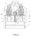
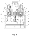
- FIGS 5-7 are section views of an inner-circulating high speed hydraulic platform comprising 4 inner-circulating high speed hydraulic systems (only two systems are shown in the figures while others are covered) in various states according to the present invention.
- a lower fixed platform 17, a right wallboard 14 and a left wallboard 14A are also illustrated in figures 5-7 , wherein a platform supporting system consisting of an upper fixed platform 13, the lower fixed platform 17, the right wallboard 14 and the left wallboard 14A is used for fixing the inner-circulating high speed hydraulic platform to a device it applied, such as a stamping machine.
- the right wallboard 14 and the left wallboard 14A are vertically connected between the upper fixed platform 13 and the lower fixed platform 17 so that the relative positions of the upper and lower fixed platform 13, 17 are fixed and a space for containing the housing of the high pressure oil chamber 22 and the moving platen 16 reciprocating therein is formed.
- housings 6 of the hydraulic cylinder components are connected to the upper fixed platform 13 through fixtures such as bolt, rivet or the like.
- the cylinder of the high pressure oil chamber 22 is contained in a via formed in the upper fixed platform 13 and also fixed to the upper fixed platform 13.
- the housings 6 of the hydraulic cylinder components or the cylinder of the high pressure oil chamber 22 may also be formed with the upper fixed platform 13 integrally.
- the inner-circulating high speed hydraulic platform and the supporting system connected as above form an integral inner-circulating high speed hydraulic platform assembly. In this way, the so-constructed inner-circulating high speed hydraulic platform assembly has a compact structure and decreases the overall height of the assembly, and is easy for transportation.
- figures 5-7 show a control system of the inner-circulating high speed hydraulic platform.
- the control system comprises a controller 1, a driver 3 for the servo motor 20 corresponding to the moving platen lifting component, and drivers (only two drivers 2 and 4 are shown in the figure) for the servo motors 5 corresponding to the hydraulic cylinder components.
- the control system is used for sending corresponding commands to the servo motor 5 of the pressure valve components of the hydraulic cylinder components, the servo motor 20 of the moving platen lifting component, and other actuators, as well as receiving related feedback information therefrom, to ensure reliable operation of the inner-circulating high speed hydraulic platform with high speed, high pressure and high precision.
- Figure 5 shows states of the respective components when the platform begins to move downward.
- a driving command for driving servo motor 20 to rotate is sent from the controller 1 to the driver 3 according to the preset action program.
- the rotation brings the lifting ball screw 18 to rotate and thus brings the engaged lifting nut 19 to follow an acceleration and deceleration curve preset by controller 1, causing the moving platen 16 to approach the lower fixed platform 17 with zero speed and press the lower fixed platform 17, i.e., arriving a state as shown in figure 6 .
- the compressed air is enabled to compress hydraulic oil 21 through compressed air inlets 7 of the inner-circulating high speed hydraulic system, causing the hydraulic oil 21 to rapidly enter the high pressure oil chamber 11 via the holes 12, thereby completing a downward stroke of the platform for oil supplying.
- the driver 3 may send an in-position signal to the controller 1 which simultaneously sends commands to drivers 2 and 4 for synchronously rotating the pressure servo motors 5.
- the pressure servo motors 5 operate synchronously and drive each pressure ball screw 3, thereby bring each pressure nut 9 to move linearly and propel the pressure plungers 10, which may firstly seal the holes 12 and compress the hydraulic oil in each high pressure cylinder 11 at the same time, thereby generate high pressure.
- the approach for synchronizing pressure servo motors 5 may use any method well known in the art, such as parallel control, master-slave control, cross-coupling control, virtual line-shaft control, relative coupling control, and so on.
- the controller 1 firstly may send rotation command to drivers 2 and 4.
- the pressure servo motors 5 also rotate according to the lifting curve preset by controller 1, bringing each pressure ball screw 8, respectively, to drive each pressure nut 9 and thus propel the pressure plungers 10 to make upward linear movement.
- the controller 1 may promptly send commands to the driver 3 for rotating the lifting servo motor 20.
- the lifting servo motors 20 drive the lifting servo ball screws 18, which in turn enable the lifting nuts 19 to bring the moving planet 16 and the hydraulic plunger 15 to move upward.
- the hydraulic oil 21 in the high pressure cylinder 11 is discharged back into the inner-circulating oil chamber through the holes 12. At this moment, all actions in the upward and downward strokes have been completed.
- the present invention is described with reference to a first embodiment of an inner-circulating high speed hydraulic platform comprising four inner-circulating high speed hydraulic systems, the number of the inner-circulating high speed hydraulic systems in the present invention is not limited to four, but may be any number more than one.
- controller described herein may be implemented as a well known controller in the art, such as PLC, motion controller, and so on.
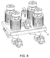
- FIG 8 shows a perspective view of an inner-circulating high speed hydraulic platform according to a second embodiment of the present invention.
- the inner-circulating high speed hydraulic platform mainly comprises: a lower fixed platform 13', a moving platen lifting component, a plurality of inner-circulating high speed hydraulic systems (for example, 2, 3, 5 etc. and specifically 4 in the present embodiment) mounted to the lower fixed platform 13', and a control system (not shown).
- the moving platen lifting component is used for pushing a moving platen 16 to move toward an upper fixed platform 17' and contact it with zero speed (See, figure 9 ).
- the inner-circulating high speed hydraulic systems are used for supplying fluid to the hydraulic system when pushing the moving platen 16 toward the upper fixed platform 17' and applying pressure on the upper fixed platform 17' after contacting the moving platen 16.
- the control system is used for sending corresponding commands to components according to action requirements and receiving related feedback information so as to ensure reliable operation of the inner-circulating high speed hydraulic platform with high speed, high pressure and high precision.
- FIGS 9-11 are section views of an inner-circulating high speed hydraulic platform comprising 4 inner-circulating high speed hydraulic systems (only two systems are shown in the figures while others are covered) in various states according to the present invention.
- the inner-circulating high speed hydraulic platform comprises four identical inner-circulating high speed hydraulic systems.
- the present invention is not limited to four identical inner-circulating high speed hydraulic systems but may take any appropriate number of systems, such as 2, 3, etc.
- the four inner-circulating high speed hydraulic systems may have similar structure and operational process to those of the first embodiment. Herein, only one of the systems is described in details with reference to figure 9 .
- the hydraulic cylinder component shown in the left side of the figure 9 comprises a high pressure cylinder 11, a hydraulic plunger 15, and a housing 6.
- An axial hole, disposed at the bottom of the high pressure cylinder 11, may communicate with a chamber on the bottom of the hydraulic plunger 15.
- At least one radial hole(s) 12 intersecting with the axial hole is also disposed near the bottom of the high pressure cylinder 11.
- the plunger 15 reciprocates in the high pressure cylinder 15, the upper end of which may connect to an actuating element, which in the preferred embodiment is a moving platen 16.
- the housing 6 contains the high pressure cylinder 11 and form a sealed inner-circulating chamber outside.
- the inner-circulating chamber may communicate with the axial hole via the aforementioned at least one radial hole 12 and in turn communicate with the bottom of the hydraulic plunger 15.
- a compressed air inlet 7 is disposed at the top of the housing 6 for introducing compressed air.
- a pressure valve component comprising a pressure servo motor 5 and a pressure plunger 10 is disposed at the bottom of the hydraulic cylinder component.
- the pressure plunger 10 may be driven by the pressure servo motor 5 to move up and down within an axial hole disposed at the bottom of the high pressure cylinder 11.
- a driving mechanism may be disposed between the pressure servo motor 5 and the pressure plunger 10.
- the driving mechanism comprises a pressure ball screw 8 and a pressure nut 9 which is engaged with the pressure ball screw 8 for moving.
- the pressure ball screw 8 is connected to the pressure servo motor 5 and supported by a bearing to rotate.
- the pressure nut 9 is connected to a pressure plunger 10.
- pressure plunger 10 may be directly driven by a linear servo motor 5, if desired.
- the functions of the pressure valve component are as follows.
- the pressure servo motor 5 enables the pressure plunger 10 to appropriately turn off hydraulic oil in at least one radial hole 12 of the hydraulic cylinder component according to command(s) received from the control system, which in turn enables the pressure plunger 10 to move into the high pressure chamber 22 at the bottom of the hydraulic plunger 15.
- the pressure plunger 10 continues to move upward, the low pressure hydraulic oil 21 at the bottom of the hydraulic plunger 15 will be compressed, which will increase the pressure in the sealed chamber (up to 400kg / cm 2 ) and cause a significant thrust on the hydraulic plunger 15.
- the generated thrust of the hydraulic plunger 15 and its highly precise position may be controlled.
- Figure 9 also show a moving platen lifting component.
- the moving platen lifting component is connected to said moving platen 16, comprising: a lifting servo motor 20 and a lifting mechanism.
- the lifting mechanism may be driven by the lifting servo motor 20, causing the moving platen 16 to perform lifting movement according to a preset lifting curve.
- the lifting mechanism comprises a lifting ball screw 18 and a lifting nut 19 engaged with the lifting ball screw 18 for moving.
- the lifting ball screw 18 is connected to the lifting servo motor 20 while the lifting nut 9 is connected to the moving platen 16.
- the moving platen lifting component enables the moving platen 16 to approach the fixed platen with high speed and zero-speed contact with the fixed platen with high precision and press it tightly. Meanwhile, the hydraulic plunger 15 fixed on the moving platen 16 is pulled to have the high pressure hydraulic cylinder 11 thereon oil supplied or discharged.
- the hydraulic system is in a static state.
- low pressure compressed air enters an inner-circulating oil chamber via a compressed air inlet 7, causing the hydraulic oil 20 to flow into the bottom of the hydraulic plunger 15 through the radial holes 12 along direction A so that the hydraulic plunger 15 is enabled to generate an upward low pressure thrust.
- the moving platen lifting component is constrained by a static torque generated from the servo motor 20, which in turn constrains the moving platen 16 and the hydraulic plunger 15 to maintain in a static state as shown in figure 9 .
- This state is referred as "state of origin" for the hydraulic system in the present invention.
- the hydraulic oil 21 propelled by the low pressure compressed air flows into the bottom of the hydraulic plunger 15 through the radial hole 12.
- the lifting servo motor 20 rotates according to the commands sent from the control system, causing the lifting ball screw 18 to engage with the lifting ball nut 19, which in turn propels the moving platen 16 fixed to the hydraulic plunger 15 to move toward the upper fixed platform 17' according to a preset downward curve for approaching and tightly pressing the upper fixed platform 17' without shock.
- the pressure servo motor 5 is initiated to drive the pressure ball screw 8 to rotate so that the pressure nut 9 propels the pressure plunger 10 to move upward in the figure.
- the pressure plunger 10 During the movement of the pressure plunger 10, it will firstly turn off the radial hole 12 at the bottom of the hydraulic plunger 15 so as to form a sealed "high pressure cylinder" below the bottom of the hydraulic plunger 15.
- the hydraulic oil in the sealed high pressure cylinder is compressed to generate a high pressure (for example, 400kgcm 2 ), which in turn enables the hydraulic plunger 15 to generate a huge thrust.
- a high pressure for example, 400kgcm 2
- the lifting servo motor 20 rotates reversely, bringing the moving platen 16 together with the cylinder plunger 15 to move downward so that the hydraulic oil 21 may be completely discharged via the radial hole 12.
- the platform returns back to the state shown in figure 9 waiting for next action command.
- an upper fixed platform 17', a right wallboard 14 and a left wallboard 14A are also illustrated in figures 9-11 , wherein a platform supporting system consisting of an lower fixed platform 13', the upper fixed platform 17', the right wallboard 14 and the left wallboard 14A is used for fixing the inner-circulating high speed hydraulic platform to a device, such as a stamping machine, to which it applied.
- the right wallboard 14 and the left wallboard 14A are vertically connected between the lower fixed platform 13' and the upper fixed platform 17' so that the relative positions of the lower and upper fixed platform 13', 17' are fixed and a space for containing the housing of the high pressure oil chamber 22 and the moving platen 16 reciprocating therein is formed.
- housings 6 of the hydraulic cylinder component are connected to the lower fixed platform 13' through fixtures such as bolt, rivet or the like.
- the pressure valve component passes through a via formed in the lower fixed platform 13' and is also fixed to the lower fixed platform 13'.
- the housings 6 of the hydraulic cylinder component or the cylinder of the high pressure oil chamber 22 may also be formed with the lower fixed platform 13' integrally.
- the inner-circulating high speed hydraulic platform and the supporting system connected as above form an integral inner-circulating high speed hydraulic platform assembly. In this way, the so-constructed inner-circulating high speed hydraulic platform assembly has a compact structure, decreases the overall height of the assembly, and thereby is easy for transportation.
- figures 9-11 also show a control system of the inner-circulating high speed hydraulic platform.
- the control system of the present invention comprises a controller 1, a driver 3 for the servo motor 20 corresponding to the moving platen lifting component, and drivers (only two drivers 2 and 4 are shown in the figure) for the servo motor 5 corresponding to the hydraulic cylinder components.
- the control system is used for sending corresponding commands to the servo motor 5 of the pressure valve components of the hydraulic cylinder components, the servo motor 20 of the moving platen lifting component, and other actuators, as well as receiving related feedback information therefrom, to ensure reliable operation of the inner-circulating high speed hydraulic platform with high speed, high pressure and high precision.
- Figure 9 shows states of components when the platform begins to move upward.
- a driving command for driving servo motor 20 to rotate is sent from the controller 1 to the driver 3 according to the preset action program.
- the rotation brings the lifting ball screw 18 to rotate and thus brings the engaged lifting ball nut 19 to follow an acceleration and deceleration curve preset by controller 1, causing the moving platen 16 to approach the upper fixed platform 17' with zero speed and tightly press the upper fixed platform 17', i.e., arriving a state as shown in figure 10 .
- the compressed air is enabled to compress hydraulic oil 21 through compressed air inlets 7 of the inner-circulating high speed hydraulic system, causing hydraulic oil 21 to rapidly enter a high pressure oil chamber 11 through the holes 12, thereby completing an upward stroke of the platform for oil supplying.
- the driver 3 sends an in-position signal to the controller 1 which simultaneously sends commands to drivers 2 and 4 for synchronously rotating the pressure servo motors 5.
- the pressure servo motors 5 operate synchronously and drive each pressure ball screw 3, respectively to bring each pressure nut 9 to move linearly and propel the pressure plungers 10, which may firstly seal the holes 12 and compress the hydraulic oil in each high pressure cylinder 11 at the same time, thereby generating high pressure.
- the approach for synchronizing pressure servo motors 5 may use any method well known in the art, such as parallel control, master-slave control, cross-coupling control, virtual line-shaft control, relative coupling control, and so on.
- the controller 1 firstly sends rotation commands to drivers 2 and 4.
- the pressure servo motors 5 also rotate according to the lifting curve preset by controller 1, bringing each pressure ball screw 8, respectively, to drive each pressure nut 9 and propel the pressure plungers 10 to make downward linear movement.
- the controller may send commands to the driver 3 for rotating the lifting servo motor 20.
- the lifting servo motors 20 drive the lifting servo ball screws 18 to enable the lifting nuts 19 to bring the moving planet 16 and the hydraulic plunger 15 to move downward.
- the hydraulic oil 21 in the high pressure cylinder 11 is discharged back into the inner-circulating oil chamber through the holes 12. At this moment, all actions in the downward strokes have been completed.
- the present invention is described with reference to a second embodiment of an inner-circulating high speed hydraulic platform comprising four inner-circulating high speed hydraulic systems, the number of the inner-circulating high speed hydraulic systems in the present invention is not limited to four, but may be any number more than one.
- controller described herein may be implemented as a well known controller in the art, such as PLC, motion controller, and so on.
Landscapes
- Engineering & Computer Science (AREA)
- Mechanical Engineering (AREA)
- General Engineering & Computer Science (AREA)
- Physics & Mathematics (AREA)
- Fluid Mechanics (AREA)
- Chemical & Material Sciences (AREA)
- Analytical Chemistry (AREA)
- Press Drives And Press Lines (AREA)
- Control Of Presses (AREA)
- Actuator (AREA)
Abstract
Description
- The present invention is generally related to a hydraulic system, a hydraulic platform and a hydraulic platform assembly used in stamping processes. In particular, the present invention relates to an inner-circulating high speed hydraulic system which performs hydraulic actions in high speed with inner circulation, and also relates to an inner-circulating high speed hydraulic platform and an inner-circulating high speed hydraulic platform assembly comprising the inner-circulating high speed hydraulic system.
- In stamping processes for packaging and printing industry, a stamping platform of a platen foil stamping machine is desired to maintain a constant paper-pressing time regardless of speeds, and set adaptive pressing times according to different requirements of products to be stamped, thereby achieving hot stamping pictures with high quality. At present, for a mechanical moving-platform consisting of crank shaft and swing-rod transmission mechanism, the dwell time for pressing at a stop point on the platform varies with changing speeds due to its inherent structure. Thus, it is difficult to guarantee quality of prints. While for hydraulic platforms consisting of conventional hydraulic servo systems, its hydraulic system mainly comprises a hydraulic valve, a hydraulic cylinder, a servo valve, an energy storage system, and lines. Such kind of a conventional hydraulic system has numerous components and complicated structures, causing a relatively high maintenance cost and defects of low efficiency and loud noise. Current hydraulic systems in the art can hardly provide hydraulic actions with high speed, high pressure and high precision at the same time. Thus, further improvements are needed.
- Accordingly, it is desired to improve moving-platform systems in stamping processes, enabling the moving-platform systems to accurate control the dwell time for pressing at upper and lower stop points of platforms, adjust the length of the dwell time as required, and provide hydraulic actions with high speed, high pressure and high precision at the same time.
- Aiming at the above defects, an objective of the present invention is to provide an inner-circulating high speed hydraulic system with simple structure, high efficiency and high precision, an inner-circulating high speed hydraulic platform and an inner-circulating high speed hydraulic platform assembly comprising the inner-circulating high speed hydraulic system by combining servo motor technology with inner-circulating pressing technology.
- Based on the above objective, the present invention firstly provides an inner-circulating high speed hydraulic system, comprising: a hydraulic cylinder assembly and a pressure valve assembly, the hydraulic cylinder assembly including a high pressure cylinder, a hydraulic plunger, and a housing, wherein an axial hole disposed at the top of the high pressure cylinder may communicate with a chamber on the top of the hydraulic plunger, wherein at least one radial hole intersecting with the axial hole is also disposed near the top of the high pressure cylinder, wherein the plunger reciprocates in the high pressure cylinder, wherein the housing contains the high pressure cylinder and forms a sealed inner-circulating oil chamber outside, wherein the inner-circulating oil chamber may communicate with the axial hole via the at least one radial hole and in turn communicate with the top of the hydraulic plunger, wherein a compressed air inlet is disposed on the upper portion of the housing and the lower end of the hydraulic plunger is connected to an actuating element; and the pressure valve assembly comprising a pressure servo motor and a pressure plunger, the pressure plunger may be driven by the pressure servo motor to move up and down within the axial hole disposed on the top of the high pressure cylinder.
- Preferably, the actuating element is a moving platen of a moving platform.
- Preferably, the hydraulic system further comprises a moving platen lifting component connected to the moving platen, and comprising: a lifting servo motor and a lifting mechanism, wherein the lifting mechanism may be driven by the lifting servo motor so that the moving platen may have lifting motion according to a preset lifting curve.
- By using the lifting mechanism, the stroke and the stop positions of the moving platen might be accurately controlled.
- Preferably, the lifting mechanism comprises a lifting ball screw and a lifting nut engaged with the lifting ball screw for moving, wherein the lifting ball screw is connected to the lifting servo motor while the lifting nut is connected to the moving platen.
- Preferably, a driving mechanism may be disposed between the pressure servo motor and the pressure plunger.
- Preferably, the driving mechanism comprises a pressure ball screw and a pressure nut engaged with the pressure ball screw for moving, wherein the pressure ball screw is connected to the pressure servo motor while the pressure nut is connected to the pressure plunger.
- Preferably, the pressure plunger may be directly driven by a linear servo motor.
- The present invention further provides an inner-circulating high speed hydraulic platform, comprising: an upper fixed platform on which at least one aforementioned inner-circulating high speed hydraulic system is connected; a moving platen lifting assembly connected to an actuating element, comprising a lifting servo motor and a lifting mechanism driven by the lifting servo motor to facilitate the actuating element to perform lifting motion; and a control system for controlling the above components to act in proper time and controlling the servo motors in the inner-circulating high speed hydraulic system to operate synchronously.
- Preferably, the lifting mechanism comprises a lifting ball screw and a lifting nut engaged with the lifting ball screw for moving, wherein the lifting ball screw is connected to the lifting servo motor while the lifting nut is connected to the moving platen.
- Preferably, the control system comprises a controller and drivers corresponding to the pressure servo motors of the at least one inner-circulating high speed hydraulic system as well as a driver corresponding to the lifting servo motor, wherein the controller is configured to: send actuating commands to the driver corresponding to the lifting servo motor so that the hydraulic plunger is driven to move downward, which in turn brings the actuating element to move downward; when the actuating element stops moving downward, the controller may receive an in-position signal from the driver of the lifting servo motor and send commands to each driver of the pressure servo motors for synchronously running so as to synchronously drive each pressure plunger entering into high pressure oil chambers and sealing the radial holes; send commands to each driver of the pressure servo motors for synchronously reverse running so as to synchronously drive each pressure plunger to synchronously exit the high pressure oil chambers upward; and send commands to the driver of the lifting servo motor for driving the hydraulic plunger to move reversely, which in turn brings the actuating element to move upward.
- Preferably, controlling pressure servo motors for synchronously running includes any of parallel control, master-slave control, cross-coupling control, virtual line-shaft control, and relative coupling control.
- Preferably, the controller is a PLC or a motion controller.
- The present invention further provides an inner-circulating high speed hydraulic platform assembly, comprising: an aforementioned inner-circulating high speed hydraulic platform; a moving platen connected to the actuating element; an upper fixed platform with which the moving platen may contact with zero speed and press against tightly when the actuating element reciprocates to the upper stop point; a lower fixed platform with which the moving platen may contact with zero speed and press against tightly when the actuating element reciprocates to the lower stop point; and a connecting mechanism for connecting and fixing the upper fixed platform and the lower fixed platform, wherein housings of hydraulic cylinder components are fixed to the upper fixed platform, wherein the high pressure cylinder is contained in a via formed in the upper fixed platform and fixed to said upper fixed platform.
- Preferably, the connecting mechanism comprises a right wallboard and a left wallboard which are connected between the upper and lower fixed platform.
- The present invention further provides another inner-circulating high speed hydraulic platform, comprising:
- a lower fixed platform, connected thereon with:
- at least one inner-circulating high speed hydraulic system, comprising:
- a hydraulic cylinder component, including a high pressure cylinder, a hydraulic plunger, and a housing, wherein an axial hole disposed at the bottom of the high pressure cylinder may communicate with a chamber in the lower portion of the hydraulic plunger, wherein at least one radial hole intersecting with the axial hole is also disposed near the bottom of the high pressure cylinder, wherein the plunger reciprocates in the high pressure cylinder, wherein the housing contains the high pressure cylinder and forms a sealed inner-circulating oil chamber outside, wherein the inner-circulating oil chamber may communicate with the axial hole via the at least one radial hole and further in turn communicate with the chamber in the lower portion of the hydraulic plunger, wherein a compressed air inlet is disposed on the housing and an upper end of the hydraulic plunger is connected to a actuating element; and
- a pressure valve component, comprising a pressure servo motor and a pressure plunger driven by the pressure servo motor to move up and down within the axial hole disposed at the bottom of the high pressure cylinder;
- a moving platen lifting component connected to the actuating element and comprising a lifting servo motor and a lifting mechanism, wherein the lifting mechanism may be driven by the lifting servo motor to enable the actuating element to perform lifting motion; and
- a control system for controlling the above components to act in proper time and controlling the servo motors in the inner-circulating high speed hydraulic system to operate synchronously.
- Preferably, the lifting mechanism comprises a lifting ball screw and a lifting nut engaged with the lifting ball screw for moving, wherein the lifting ball screw is connected to the lifting servo motor while the lifting nut is connected to the moving platen.
- Preferably, the control system comprises a controller and drivers corresponding to the pressure servo motors of the at least one inner-circulating high speed hydraulic system as well as a driver corresponding to the lifting servo motor, wherein the controller is configured to send actuating commands to the driver corresponding to the lifting servo motor so that the hydraulic plunger is driven to move upward, which in turn brings the actuating element to move upward; when the actuating element stops moving upward, the controller may receive an in-position signal from the driver of the lifting servo motor and send commands to each driver of the pressure servo motors for synchronously running so as to synchronously drive each pressure plunger synchronously entering into high pressure oil chambers and sealing the radial holes; send commands to each driver of the pressure servo motors for synchronously reverse running so as to synchronously drive each pressure plunger to synchronously exit the high pressure oil chambers downward; and send commands to the driver of the lifting servo motor for driving the hydraulic plunger to move reversely, which in turn brings the actuating element to move downward.
- Preferably, controlling pressure servo motors for synchronously running includes any of parallel control, master-slave control, cross-coupling control, virtual line-shaft control, and relative coupling control.
- Preferably, the controller is a PLC or a motion controller.
- The present invention further provides another inner-circulating high speed hydraulic platform assembly, comprising: an aforementioned inner-circulating high speed hydraulic platform; a moving platen connected to the actuating element; an upper fixed platform with which the moving platen may contact with zero speed and press against tightly when the actuating element reciprocates to the upper stop point; and a connecting mechanism for connecting and fixing the lower fixed platform and the upper fixed platform, wherein housings of hydraulic cylinder assemblies are fixed to the lower fixed platform, wherein a pressure valve component passes through a via formed in the lower fixed platform and is fixed to the lower fixed platform.
- Preferably, the connecting mechanism comprises a right wallboard and a left wallboard which are connected between the lower and upper fixed platforms.
- The inner-circulating high speed hydraulic system in the present invention combines servo motor technology with inner-circulating pressing technology. By means of the hydraulic system in the present invention, hydraulic pumps, servo valves, energy storage systems and all hydraulic lines in conventional hydraulic systems may be eliminated. As the present system does not need all lines and servo valves in conventional technologies, hydraulic loss is very little and operational efficiency is much higher than existing technologies.
- Further, with the inner-circulating high speed hydraulic platform in the present invention, inner-circulation and pressurization of hydraulic oil are achieved while number of components is merely one third of that in conventional moving-platform. A stamping process with a high speed of 8000 sheets/hour and a positional repeatability of ±0.01mm is able to be realized. Furthermore, accurate control on dwell time for pressing at upper and lower stop points of platforms and adjustment to lengths of dwell time are enabled. Thus, a high quality stamping process is accomplished. Meanwhile, the inner-circulating high speed hydraulic platform is also highly applicable in other stamping devices requiring high speed, high pressure and high precision.
- The inner-circulating high speed hydraulic platform assembly in the present invention has a compact structure with decreased overall height, and is easy for transportation.
- Other features and advantages of the present invention will become more obvious from the detailed description set forth below when taken in conjunction with the drawings. In the drawings:
-
Figure 1 illustrates a perspective view of an inner-circulating high speed hydraulic platform according to a first embodiment of the present invention, wherein a support for fixing the inner-circulating high speed hydraulic platform to a stamping machine, a control system, a moving platen and a lower fixed platform are omitted for clarity; -
Figure 2 is a static section view of an inner-circulating high speed hydraulic system according to a first embodiment of the present invention; -
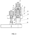
Figure 3 is a section view of an inner-circulating high speed hydraulic system in a pressured state according to the first embodiment of the present invention; -
Figure 4 is a section view of an inner-circulating high speed hydraulic system in a pressure-released state according to the first embodiment of the present invention; -
Figures 5-7 are section views of an inner-circulating high speed hydraulic platform comprising four inner-circulating high speed hydraulic systems in various states according to the present invention; -
Figure 8 illustrates a perspective view of an inner-circulating high speed hydraulic platform according to a second embodiment of the present invention, wherein a support for fixing the inner-circulating high speed hydraulic platform to a stamping machine, a control system, a moving platen and an upper fixed platform are omitted for clarity; and -
Figures 9-11 are section views of an inner-circulating high speed hydraulic platform in various states according to the second embodiment of the present invention. -
Figure 1 shows a perspective view of an inner-circulating high speed hydraulic platform according to a first embodiment of the present invention. The inner-circulating high speed hydraulic platform mainly comprises: an upperfixed platform 13, a moving platen lifting component, a plurality of inner-circulating high speed hydraulic systems (for example, 2, 3, and 5 etc. and specifically 4 in the present embodiment) mounted to the upperfixed platform 13, and a control system (not shown). The moving platen lifting component is used for pushing a movingplaten 16 to move toward a lowerfixed platform 17 and contact the lowerfixed platform 17 with zero speed (Seefigure 2 ). The inner-circulating high speed hydraulic systems are used for supplying fluids to the hydraulic system when pushing the movingplaten 16 toward the lower fixedplatform 17 and applying pressure on the lower fixedplatform 17 after the movingplaten 16 contacting with the lower fixedplatform 17. The control system is used for sending corresponding commands to the respective components according to action requirements and receiving related feedback information so as to ensure reliable operation of the inner-circulating high speed hydraulic platform with high speed, high pressure and high precision. - In this embodiment, the inner-circulating high speed hydraulic platform comprises four identical inner-circulating high speed hydraulic systems. However, it should be understood that the present invention is not limited to four identical inner-circulating high speed hydraulic systems, but may have any appropriate number of systems, such as 2, 3, etc. Those four identical inner-circulating high speed hydraulic systems have same structures and operational processes. Herein, only one of the systems is described in details with reference to
figures 2-4 . -
Figure 2 shows a stationary state of an inner-circulating high speed hydraulic system as well as a moving platen lifting component according to a first embodiment of the present invention. The inner-circulating high speed hydraulic system includes a hydraulic cylinder component and a pressure valve component. - The hydraulic cylinder component includes: a
high pressure cylinder 11, ahydraulic plunger 15, and ahousing 6. An axial hole, disposed on the top of thehigh pressure cylinder 11, may communicate with a chamber on the top of thehydraulic plunger 15. At least one radial hole(s) 12 intersecting with the axial hole is also disposed near the top of thehigh pressure cylinder 11. Theplunger 15 reciprocates in thehigh pressure cylinder 11 and the lower end of theplunger 15 may connect to an actuating element, which in a preferred embodiment is a movingplaten 16. Thehousing 6 contains the high pressure cylinder and forms a sealed inner-circulating oil chamber outside. The inner-circulating oil chamber may communicate with the axial hole with the aforementioned at least oneradial hole 12 and in turn communicate with the top of thehydraulic plunger 15. In addition, acompressed air inlet 7 is disposed in the upper portion of thehousing 6 for introducing compressed air. - A pressure valve component comprising a
pressure servo motor 5 and apressure plunger 10 is disposed on the top of the hydraulic cylinder component. Thepressure plunger 10 may be driven by thepressure servo motor 5 to move up and down within an axial hole disposed on the top of thehigh pressure cylinder 11. In this embodiment, a driving mechanism may be disposed between thepressure servo motor 5 and thepressure plunger 10. The driving mechanism comprises apressure ball screw 8 and apressure nut 9 engaged with thepressure ball screw 8 for moving. Thepressure ball screw 8 is connected to thepressure servo motor 5 and supported by a bearing to rotate. Thepressure nut 9 is connected to apressure plunger 10. - It should be understood that the
pressure plunger 10 may be directly driven by alinear servo motor 5, if desired. - The functions of the pressure valve component are as follows. The
pressure servo motor 5 enables thepressure plunger 10 to appropriately turn off hydraulic oil in at least oneradial hole 12 of the hydraulic cylinder component according to command(s) received from the control system, which in turn enables thepressure plunger 10 to move into the highpressure oil chamber 22 at the top of thehydraulic plunger 15. When the pressure plunger continues to move downward, the low pressurehydraulic oil 21 in the top of thehydraulic plunger 15 will be compressed, which will increase the pressure in the seal chamber (up to 400kg / cm2) and generate a significant thrust on thehydraulic plunger 15. Provided that the moving distance of thepressure plunger 10 toward thehydraulic plunger 15 is controlled, the generated thrust of thehydraulic plunger 15 and its highly precise position (for example, with a positional repeatability of ±0.01mm) may be controlled. -
Figure 2 also shows a moving platen lifting component. The moving platen lifting component is connected to said movingplaten 16, comprising: a liftingservo motor 20 and a lifting mechanism. The lifting mechanism may be driven by the liftingservo motor 20, causing the movingplaten 16 to perform lifting motion according to a preset lifting curve. In this embodiment, the lifting mechanism comprises a liftingball screw 18 and a liftingnut 19 engaged with the liftingball screw 18 for moving. The liftingball screw 18 is connected to the liftingservo motor 20 while the liftingnut 19 is connected to the movingplaten 16. - The moving platen lifting component enables the moving
platen 16 to approach the fixed platform with high speed and zero-speed contact with the fixed platform with high precision and press it tightly. Meanwhile, thehydraulic plunger 15 fixed on the movingplaten 16 is pulled to have the high pressurehydraulic cylinder 11 thereon oil supplied or discharged. - Hereinafter, the action process of the hydraulic system according to a preferred embodiment of the present invention will be described with respect to
figures 2-4 . - In
figure 2 , the hydraulic system is in a stationary state. In this state, low pressure compressed air enters an inner-circulating oil chamber via acompressed air inlet 7, causing thehydraulic oil 20 to flow into the top of thehydraulic plunger 15 throughradial holes 12 along direction A so that thehydraulic plunger 15 is enabled to generate a low pressure thrust downward. At this time, the moving platen lifting component is constrained by a static torque generated from theservo motor 20, which in turn constrains the movingplaten 16 and thehydraulic plunger 15 to maintain in a stationary state as shown infigure 2 . This state is referred as "origin state " for the hydraulic system in the present invention. - With reference to
figure 3 , thehydraulic oil 21 propelled by the low pressure compressed air flows into the top of thehydraulic plunger 15 through the radial holes 12. At this time, the liftingservo motor 20 rotates according to the command sent from the control system, causing the liftingball screw 18 to engage with the liftingball nut 19, which in turn propels the movingplaten 16 fixed to thehydraulic plunger 15 to move toward the lower fixedplatform 17 according to a preset downward curve for approaching and pressing the lower fixedplatform 17 without shocks. Thus, the action of "oil supplying with low pressure" is completed. Subsequently, thepressure servo motor 5 is initiated to drive thepressure ball screw 8 to rotate so that thepressure nut 9 propels thepressure plunger 10 to move downward in the figure. During the movement of thepressure plunger 10, it will firstly turn off theradial hole 12 at the top of thehydraulic plunger 15 so as to form a sealed "high pressure cylinder" on the top of thehydraulic plunger 15. When thepressure plunger 10 continues to move downward, the hydraulic oil in the sealed high pressure cylinder is compressed to generate a high pressure(for example, 400kg/cm2) within the high pressure cylinder, which in turn enables thehydraulic plunger 15 to generate a huge thrust. Provided that the rotation angle of thepressure servo motor 5 is changed, the moving position of thepressure plunger 10 might be changed and accordingly the thrust and position of the hydraulic plunger might also be changed. - With reference to
figure 4 , when the movingplaten 16 is required to move upward back to the stationary state as shown infigure 2 , thepressure servo motor 5 drives the pressure ball screw to rotate reversely. Then thepressure nut 9 will bring thepressure plunge 10 to move upward. When thepressure plunger 10 arrives at a position at which theradial hole 12 begins to be exposed, high pressure oil in said "high pressure cylinder" will discharge oil to the inter-circulating chamber along the direction B. - At this time, the lifting
servo motor 20 rotates reversely, bringing the movingplaten 16 together with thecylinder plunger 15 to move upward so that thehydraulic oil 21 may be completely discharged via the radial holes 12. Thus, all actions within a stroke are completed. Then, the platform returns back to the state shown infigure 2 , waiting for next active command. -
Figures 5-7 are section views of an inner-circulating high speed hydraulic platform comprising 4 inner-circulating high speed hydraulic systems (only two systems are shown in the figures while others are covered) in various states according to the present invention. - In addition to the inner-circulating high speed hydraulic platform, a lower fixed
platform 17, aright wallboard 14 and aleft wallboard 14A are also illustrated infigures 5-7 , wherein a platform supporting system consisting of an upper fixedplatform 13, the lower fixedplatform 17, theright wallboard 14 and theleft wallboard 14A is used for fixing the inner-circulating high speed hydraulic platform to a device it applied, such as a stamping machine. Theright wallboard 14 and theleft wallboard 14A are vertically connected between the upper fixedplatform 13 and the lower fixedplatform 17 so that the relative positions of the upper and lower fixedplatform pressure oil chamber 22 and the movingplaten 16 reciprocating therein is formed. Furthermore,housings 6 of the hydraulic cylinder components are connected to the upper fixedplatform 13 through fixtures such as bolt, rivet or the like. The cylinder of the highpressure oil chamber 22 is contained in a via formed in the upper fixedplatform 13 and also fixed to the upper fixedplatform 13. Undoubtedly, it should be understood that thehousings 6 of the hydraulic cylinder components or the cylinder of the highpressure oil chamber 22 may also be formed with the upper fixedplatform 13 integrally. The inner-circulating high speed hydraulic platform and the supporting system connected as above form an integral inner-circulating high speed hydraulic platform assembly. In this way, the so-constructed inner-circulating high speed hydraulic platform assembly has a compact structure and decreases the overall height of the assembly, and is easy for transportation. - Further,
figures 5-7 show a control system of the inner-circulating high speed hydraulic platform. With reference tofigure 5 , the control system comprises acontroller 1, adriver 3 for theservo motor 20 corresponding to the moving platen lifting component, and drivers (only twodrivers servo motors 5 corresponding to the hydraulic cylinder components. According to the action requirements, the control system is used for sending corresponding commands to theservo motor 5 of the pressure valve components of the hydraulic cylinder components, theservo motor 20 of the moving platen lifting component, and other actuators, as well as receiving related feedback information therefrom, to ensure reliable operation of the inner-circulating high speed hydraulic platform with high speed, high pressure and high precision. - Next, the operational process of the inner-circulating high speed hydraulic platform under the control of the control system will be descried with reference to
figures 5-7 . -
Figure 5 shows states of the respective components when the platform begins to move downward. When the movingplaten 16 begins to press downward, a driving command for drivingservo motor 20 to rotate is sent from thecontroller 1 to thedriver 3 according to the preset action program. The rotation brings the liftingball screw 18 to rotate and thus brings the engaged liftingnut 19 to follow an acceleration and deceleration curve preset bycontroller 1, causing the movingplaten 16 to approach the lower fixedplatform 17 with zero speed and press the lower fixedplatform 17, i.e., arriving a state as shown infigure 6 . With the downward movement of the movingplaten 16, the compressed air is enabled to compresshydraulic oil 21 throughcompressed air inlets 7 of the inner-circulating high speed hydraulic system, causing thehydraulic oil 21 to rapidly enter the highpressure oil chamber 11 via theholes 12, thereby completing a downward stroke of the platform for oil supplying. - With reference to
figure 6 , when the liftingservo motor 20 arrives zero speed, thedriver 3 may send an in-position signal to thecontroller 1 which simultaneously sends commands todrivers pressure servo motors 5. At this time, thepressure servo motors 5 operate synchronously and drive eachpressure ball screw 3, thereby bring eachpressure nut 9 to move linearly and propel thepressure plungers 10, which may firstly seal theholes 12 and compress the hydraulic oil in eachhigh pressure cylinder 11 at the same time, thereby generate high pressure. It should be understood that the approach for synchronizingpressure servo motors 5 may use any method well known in the art, such as parallel control, master-slave control, cross-coupling control, virtual line-shaft control, relative coupling control, and so on. - With reference to
figure 7 , after all actions shown infigure 6 are completed, thecontroller 1 firstly may send rotation command todrivers pressure servo motors 5 also rotate according to the lifting curve preset bycontroller 1, bringing eachpressure ball screw 8, respectively, to drive eachpressure nut 9 and thus propel thepressure plungers 10 to make upward linear movement. When the plungers move and then stop at the position as shown infigure 7 , thecontroller 1 may promptly send commands to thedriver 3 for rotating the liftingservo motor 20. At this time, the liftingservo motors 20 drive the lifting servo ball screws 18, which in turn enable the liftingnuts 19 to bring the movingplanet 16 and thehydraulic plunger 15 to move upward. At this time, thehydraulic oil 21 in thehigh pressure cylinder 11 is discharged back into the inner-circulating oil chamber through theholes 12. At this moment, all actions in the upward and downward strokes have been completed. - Although the present invention is described with reference to a first embodiment of an inner-circulating high speed hydraulic platform comprising four inner-circulating high speed hydraulic systems, the number of the inner-circulating high speed hydraulic systems in the present invention is not limited to four, but may be any number more than one.
- It should be understood that the controller described herein may be implemented as a well known controller in the art, such as PLC, motion controller, and so on.
- Descriptions regarding "upward/upper" and "downward/lower" used herein are not intended to limit the direction of components in figures during usage. It will be understood by those skilled in the art that the above system may be used inversely by modification, as will be describe with respect to the second embodiment below.
-
Figure 8 shows a perspective view of an inner-circulating high speed hydraulic platform according to a second embodiment of the present invention. The inner-circulating high speed hydraulic platform mainly comprises: a lower fixed platform 13', a moving platen lifting component, a plurality of inner-circulating high speed hydraulic systems (for example, 2, 3, 5 etc. and specifically 4 in the present embodiment) mounted to the lower fixed platform 13', and a control system (not shown). The moving platen lifting component is used for pushing a movingplaten 16 to move toward an upper fixed platform 17' and contact it with zero speed (See,figure 9 ). The inner-circulating high speed hydraulic systems are used for supplying fluid to the hydraulic system when pushing the movingplaten 16 toward the upper fixed platform 17' and applying pressure on the upper fixed platform 17' after contacting the movingplaten 16. The control system is used for sending corresponding commands to components according to action requirements and receiving related feedback information so as to ensure reliable operation of the inner-circulating high speed hydraulic platform with high speed, high pressure and high precision. -
Figures 9-11 are section views of an inner-circulating high speed hydraulic platform comprising 4 inner-circulating high speed hydraulic systems (only two systems are shown in the figures while others are covered) in various states according to the present invention. - In this embodiment, the inner-circulating high speed hydraulic platform comprises four identical inner-circulating high speed hydraulic systems. However, it should be understood that the present invention is not limited to four identical inner-circulating high speed hydraulic systems but may take any appropriate number of systems, such as 2, 3, etc. The four inner-circulating high speed hydraulic systems may have similar structure and operational process to those of the first embodiment. Herein, only one of the systems is described in details with reference to
figure 9 . - Taking the hydraulic cylinder component shown in the left side of the
figure 9 as an example, it comprises ahigh pressure cylinder 11, ahydraulic plunger 15, and ahousing 6. An axial hole, disposed at the bottom of thehigh pressure cylinder 11, may communicate with a chamber on the bottom of thehydraulic plunger 15. At least one radial hole(s) 12 intersecting with the axial hole is also disposed near the bottom of thehigh pressure cylinder 11. Theplunger 15 reciprocates in thehigh pressure cylinder 15, the upper end of which may connect to an actuating element, which in the preferred embodiment is a movingplaten 16. Thehousing 6 contains thehigh pressure cylinder 11 and form a sealed inner-circulating chamber outside. The inner-circulating chamber may communicate with the axial hole via the aforementioned at least oneradial hole 12 and in turn communicate with the bottom of thehydraulic plunger 15. In addition, acompressed air inlet 7 is disposed at the top of thehousing 6 for introducing compressed air. - A pressure valve component comprising a
pressure servo motor 5 and apressure plunger 10 is disposed at the bottom of the hydraulic cylinder component. Thepressure plunger 10 may be driven by thepressure servo motor 5 to move up and down within an axial hole disposed at the bottom of thehigh pressure cylinder 11. In this embodiment, a driving mechanism may be disposed between thepressure servo motor 5 and thepressure plunger 10. The driving mechanism comprises apressure ball screw 8 and apressure nut 9 which is engaged with thepressure ball screw 8 for moving. Thepressure ball screw 8 is connected to thepressure servo motor 5 and supported by a bearing to rotate. Thepressure nut 9 is connected to apressure plunger 10. - It should be understood that the
pressure plunger 10 may be directly driven by alinear servo motor 5, if desired. - The functions of the pressure valve component are as follows. The
pressure servo motor 5 enables thepressure plunger 10 to appropriately turn off hydraulic oil in at least oneradial hole 12 of the hydraulic cylinder component according to command(s) received from the control system, which in turn enables thepressure plunger 10 to move into thehigh pressure chamber 22 at the bottom of thehydraulic plunger 15. When thepressure plunger 10 continues to move upward, the low pressurehydraulic oil 21 at the bottom of thehydraulic plunger 15 will be compressed, which will increase the pressure in the sealed chamber (up to 400kg / cm2) and cause a significant thrust on thehydraulic plunger 15. Provided that the moving distance of thepressure plunger 10 toward the top of thehydraulic plunger 15 is controlled, the generated thrust of thehydraulic plunger 15 and its highly precise position (for example, with a positional repeatability of ±0.01mm) may be controlled. -
Figure 9 also show a moving platen lifting component. The moving platen lifting component is connected to said movingplaten 16, comprising: a liftingservo motor 20 and a lifting mechanism. The lifting mechanism may be driven by the liftingservo motor 20, causing the movingplaten 16 to perform lifting movement according to a preset lifting curve. In this embodiment, the lifting mechanism comprises a liftingball screw 18 and a liftingnut 19 engaged with the liftingball screw 18 for moving. The liftingball screw 18 is connected to the liftingservo motor 20 while the liftingnut 9 is connected to the movingplaten 16. - The moving platen lifting component enables the moving
platen 16 to approach the fixed platen with high speed and zero-speed contact with the fixed platen with high precision and press it tightly. Meanwhile, thehydraulic plunger 15 fixed on the movingplaten 16 is pulled to have the high pressurehydraulic cylinder 11 thereon oil supplied or discharged. - Hereinafter, the action process of the hydraulic system according to a preferred embodiment of the present invention will be described with respect to
figures 9-11 . - In
figure 9 , the hydraulic system is in a static state. In this state, low pressure compressed air enters an inner-circulating oil chamber via acompressed air inlet 7, causing thehydraulic oil 20 to flow into the bottom of thehydraulic plunger 15 through the radial holes 12 along direction A so that thehydraulic plunger 15 is enabled to generate an upward low pressure thrust. At this time, the moving platen lifting component is constrained by a static torque generated from theservo motor 20, which in turn constrains the movingplaten 16 and thehydraulic plunger 15 to maintain in a static state as shown infigure 9 . This state is referred as "state of origin" for the hydraulic system in the present invention. - With reference to
figure 10 , thehydraulic oil 21 propelled by the low pressure compressed air flows into the bottom of thehydraulic plunger 15 through theradial hole 12. At this time, the liftingservo motor 20 rotates according to the commands sent from the control system, causing the liftingball screw 18 to engage with the liftingball nut 19, which in turn propels the movingplaten 16 fixed to thehydraulic plunger 15 to move toward the upper fixed platform 17' according to a preset downward curve for approaching and tightly pressing the upper fixed platform 17' without shock. Thus, the action of "oil supplying with low pressure" is completed. Subsequently, thepressure servo motor 5 is initiated to drive thepressure ball screw 8 to rotate so that thepressure nut 9 propels thepressure plunger 10 to move upward in the figure. During the movement of thepressure plunger 10, it will firstly turn off theradial hole 12 at the bottom of thehydraulic plunger 15 so as to form a sealed "high pressure cylinder" below the bottom of thehydraulic plunger 15. When thepressure plunger 10 continues to move upward, the hydraulic oil in the sealed high pressure cylinder is compressed to generate a high pressure (for example, 400kgcm2), which in turn enables thehydraulic plunger 15 to generate a huge thrust. Provided that the rotation angle of thepressure servo motor 5 is changed, the moving position of thepressure plunger 10 might be changed, and accordingly the thrust and position of the hydraulic plunger might also be changed. - With reference to
figure 11 , when the movingplaten 16 is required to move downward to return to the stationary state as shown infigure 9 , thepressure servo motor 5 drives the pressure ball screw to rotate reversely. Then thepressure nut 9 will bring thepressure plunge 10 to move downward. When thepressure plunger 10 moves to a position at which theradial hole 12 begins to be exposed, high pressure oils in said "high pressure cylinder" will discharge oil to the inter-circulating chamber. - At this time, the lifting
servo motor 20 rotates reversely, bringing the movingplaten 16 together with thecylinder plunger 15 to move downward so that thehydraulic oil 21 may be completely discharged via theradial hole 12. Thus, all actions within a stroke are completed. Then, the platform returns back to the state shown infigure 9 waiting for next action command. - In addition to the inner-circulating high speed hydraulic platform, an upper fixed platform 17', a
right wallboard 14 and aleft wallboard 14A are also illustrated infigures 9-11 , wherein a platform supporting system consisting of an lower fixed platform 13', the upper fixed platform 17', theright wallboard 14 and theleft wallboard 14A is used for fixing the inner-circulating high speed hydraulic platform to a device, such as a stamping machine, to which it applied. Theright wallboard 14 and theleft wallboard 14A are vertically connected between the lower fixed platform 13' and the upper fixed platform 17' so that the relative positions of the lower and upper fixed platform 13', 17' are fixed and a space for containing the housing of the highpressure oil chamber 22 and the movingplaten 16 reciprocating therein is formed. Furthermore,housings 6 of the hydraulic cylinder component are connected to the lower fixed platform 13' through fixtures such as bolt, rivet or the like. The pressure valve component passes through a via formed in the lower fixed platform 13' and is also fixed to the lower fixed platform 13'. Undoubtedly, it should be understood that thehousings 6 of the hydraulic cylinder component or the cylinder of the high pressure oil chamber 22may also be formed with the lower fixed platform 13' integrally. The inner-circulating high speed hydraulic platform and the supporting system connected as above form an integral inner-circulating high speed hydraulic platform assembly. In this way, the so-constructed inner-circulating high speed hydraulic platform assembly has a compact structure, decreases the overall height of the assembly, and thereby is easy for transportation. - Further,
figures 9-11 also show a control system of the inner-circulating high speed hydraulic platform. With reference tofigure 9 , the control system of the present invention comprises acontroller 1, adriver 3 for theservo motor 20 corresponding to the moving platen lifting component, and drivers (only twodrivers servo motor 5 corresponding to the hydraulic cylinder components. According to the action requirements, the control system is used for sending corresponding commands to theservo motor 5 of the pressure valve components of the hydraulic cylinder components, theservo motor 20 of the moving platen lifting component, and other actuators, as well as receiving related feedback information therefrom, to ensure reliable operation of the inner-circulating high speed hydraulic platform with high speed, high pressure and high precision. - Next, the operational process of the inner-circulating high speed hydraulic platform under the control of the control system will be descried with reference to
figures 9-11 . -
Figure 9 shows states of components when the platform begins to move upward. When the movingplaten 16 begins to press upward, a driving command for drivingservo motor 20 to rotate is sent from thecontroller 1 to thedriver 3 according to the preset action program. The rotation brings the liftingball screw 18 to rotate and thus brings the engaged liftingball nut 19 to follow an acceleration and deceleration curve preset bycontroller 1, causing the movingplaten 16 to approach the upper fixed platform 17' with zero speed and tightly press the upper fixed platform 17', i.e., arriving a state as shown infigure 10 . With the upward movement of the movingplaten 16, the compressed air is enabled to compresshydraulic oil 21 throughcompressed air inlets 7 of the inner-circulating high speed hydraulic system, causinghydraulic oil 21 to rapidly enter a highpressure oil chamber 11 through theholes 12, thereby completing an upward stroke of the platform for oil supplying. - With reference to
figure 10 , when the liftingservo motor 20 arrives zero speed, thedriver 3 sends an in-position signal to thecontroller 1 which simultaneously sends commands todrivers pressure servo motors 5. At this time, thepressure servo motors 5 operate synchronously and drive eachpressure ball screw 3, respectively to bring eachpressure nut 9 to move linearly and propel thepressure plungers 10, which may firstly seal theholes 12 and compress the hydraulic oil in eachhigh pressure cylinder 11 at the same time, thereby generating high pressure. It should be understood that the approach for synchronizingpressure servo motors 5 may use any method well known in the art, such as parallel control, master-slave control, cross-coupling control, virtual line-shaft control, relative coupling control, and so on. - With reference to
figure 11 , after all actions shown infigure 10 are completed, thecontroller 1 firstly sends rotation commands todrivers pressure servo motors 5 also rotate according to the lifting curve preset bycontroller 1, bringing eachpressure ball screw 8, respectively, to drive eachpressure nut 9 and propel thepressure plungers 10 to make downward linear movement. When thepressure plungers 10 move and stop the position as shown infigure 11 , the controller may send commands to thedriver 3 for rotating the liftingservo motor 20. At this time, the liftingservo motors 20 drive the lifting servo ball screws 18 to enable the liftingnuts 19 to bring the movingplanet 16 and thehydraulic plunger 15 to move downward. At this time, thehydraulic oil 21 in thehigh pressure cylinder 11 is discharged back into the inner-circulating oil chamber through theholes 12. At this moment, all actions in the downward strokes have been completed. - Although the present invention is described with reference to a second embodiment of an inner-circulating high speed hydraulic platform comprising four inner-circulating high speed hydraulic systems, the number of the inner-circulating high speed hydraulic systems in the present invention is not limited to four, but may be any number more than one.
- It should be understood that the controller described herein may be implemented as a well known controller in the art, such as PLC, motion controller, and so on.
- Descriptions regarding "upward/upper" and "downward/lower" used herein are not intended to limit the direction of components in figures during usage.
- While the present invention is specifically described with respect to the preferred embodiments, it should be understood by those skilled that various changes and modifications could be made on the basis of the aforementioned disclosure without departing from the essential thereof. Thus, the scope of the invention is defined by the appended claims.
Claims (21)
- An inner-circulating high speed hydraulic system, comprising:a hydraulic cylinder component, including a high pressure cylinder (11), a hydraulic plunger (15), and a housing (6), wherein an axial hole disposed at the top of the high pressure cylinder (11) communicates with a chamber on the top of the hydraulic plunger (15), wherein at least one radial hole (12) intersecting with the axial hole is also disposed near the top of the high pressure cylinder, wherein the hydraulic plunger (15) reciprocates in the high pressure cylinder (11), wherein the housing (6) contains the high pressure cylinder (11) and forms a sealed inner-circulating oil chamber outside, wherein the inner-circulating oil chamber communicates with the axial hole (12) via said radial hole and in turn communicate with the top of the hydraulic plunger (15), wherein a compressed air inlet (7) is disposed in the upper portion of the housing (6) and a lower end of the hydraulic plunger (15) is connected to an actuating element; anda pressure valve component, comprising a pressure servo motor (5) and a pressure plunger (10) driven by the pressure servo motor (5) to move up and down within the axial hole disposed at the top of the high pressure cylinder (11).
- The inner-circulating high speed hydraulic system of claim 1, characterized in that, the actuating element is a moving platen (16) of a moving platform.
- The inner-circulating high speed hydraulic system of claim 2, characterized in that, the hydraulic system also comprises a moving platen lifting component connected to the moving platen (16), the moving platen lifting component includes a lifting servo motor (20) and a lifting mechanism, wherein the lifting mechanism is driven by the lifting servo motor (20) so that the moving platen (16) makes a lifting movement according to a preset lifting curve.
- The inner-circulating high speed hydraulic system of claim 3, characterized in that, the lifting mechanism comprises a lifting ball screw (18) and a lifting nut (19) engaged with the lifting ball screw (18) for moving, wherein the lifting ball screw(18) is connected to the lifting servo motor(20) while the lifting nut (19) is connected to the moving platen (16).
- The inner-circulating high speed hydraulic system of claim 1, characterized in that, a driving mechanism is disposed between the pressure servo motor (5) and the pressure plunger (10).
- The inner-circulating high speed hydraulic system of claim 5, characterized in that, the driving mechanism comprises a pressure ball screw (8) and a pressure nut (9) engaged with the pressure ball screw (8) for moving, wherein the pressure ball screw(8) is connected to the pressure servo motor(5) while the pressure nut (9) is connected to the pressure platen (10).
- The inner-circulating high speed hydraulic system of claim 1, characterized in that, the pressure plunger (10) is directly driven by a linear servo motor.
- An inner-circulating high speed hydraulic platform, comprising:an upper fixed platform (13) which connects with an inner-circulating high speed hydraulic system as claimed in anyone of claims 1-2; a moving platen lifting component connected to an actuating element and comprising a lifting servo motor (6) and a lifting mechanism, wherein the lifting mechanism is driven by the lifting servo motor (6) to enable the actuating element to perform lifting movement; anda control system for controlling the above components to act in proper time and controlling the servo motors (5) in the inner-circulating high speed hydraulic system to operate synchronously.
- The inner-circulating high speed hydraulic platform of claim 8, characterized in that, the lifting mechanism comprises a lifting ball screw (18) and a lifting nut (19) engaged with the lifting ball screw (18) for moving, wherein the lifting ball screw(18) is connected to the lifting servo motor(20) while the lifting nut (19) is connected to the moving platen (16).
- The inner-circulating high speed hydraulic platform of claim 8, characterized in that, the control system comprises a controller (1), drivers (2, 4) corresponding to the pressure servo motors (5) of the at least one inner-circulating high speed hydraulic system, and a driver (3) corresponding to the lifting servo motor (20), wherein the controller (1) is configured to:send actuating commands to the driver (3) corresponding to the lifting servo motor (20) so that the hydraulic plunger (15) is driven to move downward, which in turn brings the actuating element to move downward;when the actuating element stops moving downward, the controller (1) receives an in-position signal from the driver (3) of the lifting servo motor (20) and send commands to each driver (2, 4) of the pressure servo motors (5) for synchronously running so as to synchronously drive each pressure plunger (10) to enter into high pressure oil chambers and seal the radial hole (12);send commands to each driver (2,4) of the pressure servo motors (1) for synchronously reverse running so as to synchronously drive each pressure plunger (10) to exit the high pressure oil chambers upward; andsend commands to the driver (3) of the lifting servo motor (20) for driving the hydraulic plunger (15) to move reversely, which in turn brings the actuating element to move upward.
- The inner-circulating high speed hydraulic platform of claim 10, characterized in that, the controlling pressure servo motors (5) for synchronous operation includes any of parallel control, master-slave control, cross-coupling control, virtual line-shaft control, and relative coupling control.
- The inner-circulating high speed hydraulic platform of claim 10, characterized in that, the actuating element is a PLC or a motion controller.
- An inner-circulating high speed hydraulic platform assembly, comprising:the inner-circulating high speed hydraulic platform as claimed in claim 8;a moving platen (16) connected to the actuating element;a connecting mechanism connecting and fixing the upper fixed platform (13) and the lower fixed platform (17);a lower fixed platform (17) with which the moving platen(16) contacts with zero speed and tightly press when the actuating element reciprocates to the lower stop point;housings (6) of the hydraulic cylinder (6) fixed to the upper fixed platform (13), wherein the cylinder of the high pressure oil chamber (22) is contained in a via formed in the upper fixed platform (13) and also fixed to the upper fixed platform (13).
- The inner-circulating high speed hydraulic assembly of claim 13, characterized in that, the connecting mechanism comprises a right wallboard (14) and a left wallboard (14A) which are connected between the upper fixed platform (13) and lower fixed platform (17).
- An inner-circulating high speed hydraulic platform, comprising:a lower fixed platform (13'), the lower fixed platform (13') is connected with:at least one inner-circulating high speed hydraulic system, comprising:a hydraulic cylinder component, including a high pressure cylinder (11), a hydraulic plunger (15), and a housing (6), wherein an axial hole disposed at the bottom of the high pressure cylinder (11) communicates with a chamber on the bottom of the hydraulic plunger (15), wherein at least one radial hole (12) intersecting with the axial hole is also disposed near the bottom of the high pressure cylinder, wherein the hydraulic plunger (15) reciprocates in the high pressure cylinder (11), wherein the housing (6) contains the high pressure cylinder (11) and forms a sealed inner-circulating oil chamber outside, wherein the inner-circulating oil chamber communicates with the axial hole (12) via said radial hole and in turn communicates with the bottom of the hydraulic plunger (15), wherein a compressed air inlet (7) is disposed on the upper portion of the housing (6) and an upper end of the hydraulic plunger (15) is connected to an actuating element; anda pressure valve component, comprising a pressure servo motor (5) and a pressure plunger (10) driven by the pressure servo motor (5) to move up and down within the axial hole disposed at the bottom of the high pressure cylinder (11);a moving platen component connected to the actuating element and comprising a lifting servo motor (6) and a lifting mechanism, wherein the lifting mechanism is driven by the lifting servo motor (6) to enable the actuating element to perform lifting movement; anda control system for controlling the above components to act in proper time and controlling the servo motors (5) in the inner-circulating high speed hydraulic system to operate synchronously.
- The inner-circulating high speed hydraulic platform of claim 15, characterized in that, the lifting mechanism comprises a lifting ball screw (18) and a lifting nut (19) engaged with the lifting ball screw (18) for moving, wherein the lifting ball screw(18) is connected to the lifting servo motor(20) while the lifting nut (19) is connected to the moving platen (16).
- The inner-circulating high speed hydraulic platform of claim 15, characterized in that, the control system comprises a controller (1), drivers (2, 4) corresponding to the pressure servo motors (5) of the at least one inner-circulating high speed hydraulic system, and a driver (3) corresponding to the lifting servo motor (20),
wherein the controller (1) is configured to:send actuating commands to the driver (3) corresponding to the lifting servo motor (20) so that the hydraulic plunger (15) is driven to move upward, which in turn drives the actuating element to move upward;when the actuating element stops moving upward, the controller (1) receives an in-position signal from the driver (3) of the lifting servo motor (20) and send commands to each driver (2, 4) of the pressure servo motors (5) for synchronously running to synchronously drive each pressure plunger (10) to enter into high pressure oil chambers and seal the radial hole (12);send commands to each driver (2,4) of the pressure servo motors (1) for synchronously reverse running to synchronously drive each pressure plunger (10) exiting the high pressure oil chambers downward; andsend commands to the driver (3) of the lifting servo motor (20) for driving the hydraulic plunger (15) to move reversely, which in turn brings the actuating element to move downward. - The inner-circulating high speed hydraulic platform of claim 15, characterized in that, controlling the pressure servo motors (5) for synchronous running includes any of parallel control, master-slave control, cross-coupling control, virtual line-shaft control, and relative coupling control.
- The inner-circulating high speed hydraulic platform of claim 15, characterized in that, the controller is a PLC or a motion controller.
- An inner-circulating high speed hydraulic platform assembly, comprising:the inner-circulating high speed hydraulic platform as claimed in claim 15;a moving platen(16) connected to the actuating element; a connecting mechanism connecting and fixing the lower fixed platform (13') and the upper fixed platform (17');an upper fixed platform (17') with which the moving platen(16) contacts with zero speed and tightly press against when the actuating element reciprocates to an upper stop point;
wherein housings (6) of the hydraulic cylinder (6) are fixed to the lower fixed platform (13'), wherein a pressure valve component passes through a via formed in the lower fixed platform (13') and is fixed to the lower fixed platform (13'). - The inner-circulating high speed hydraulic platform assembly of claim 20, characterized in that, the connecting mechanism comprises a right wallboard (14) and a left wallboard (14A) which are connected between the lower fixed platform (13') and the upper fixed platform (17').
Applications Claiming Priority (2)
| Application Number | Priority Date | Filing Date | Title |
|---|---|---|---|
| CN201310682896.1A CN104712616B (en) | 2013-12-12 | 2013-12-12 | Internal circulation high-speed hydraulic system, hydraulic platform and hydraulic platform component |
| PCT/CN2014/000691 WO2015085648A1 (en) | 2013-12-12 | 2014-07-21 | Inner-circulation high-speed hydraulic system, hydraulic platform, and hydraulic platform assembly |
Publications (3)
| Publication Number | Publication Date |
|---|---|
| EP3081380A1 true EP3081380A1 (en) | 2016-10-19 |
| EP3081380A4 EP3081380A4 (en) | 2017-11-29 |
| EP3081380B1 EP3081380B1 (en) | 2020-09-09 |
Family
ID=53370558
Family Applications (1)
| Application Number | Title | Priority Date | Filing Date |
|---|---|---|---|
| EP14869932.5A Active EP3081380B1 (en) | 2013-12-12 | 2014-07-21 | Inner-circulation high-speed hydraulic system, hydraulic platform, and hydraulic platform assembly |
Country Status (10)
| Country | Link |
|---|---|
| US (1) | US10875272B2 (en) |
| EP (1) | EP3081380B1 (en) |
| JP (1) | JP6246386B2 (en) |
| KR (1) | KR101945907B1 (en) |
| CN (1) | CN104712616B (en) |
| BR (1) | BR112016013575B1 (en) |
| CA (1) | CA2932028C (en) |
| MX (1) | MX2016007478A (en) |
| MY (1) | MY181087A (en) |
| WO (1) | WO2015085648A1 (en) |
Cited By (3)
| Publication number | Priority date | Publication date | Assignee | Title |
|---|---|---|---|---|
| CN106427199A (en) * | 2016-10-17 | 2017-02-22 | 江苏劲嘉新型包装材料有限公司 | Honey comb plate structure for completing concave stamping and concave-convex machining of hot stamping machine at a time |
| IT201600131917A1 (en) * | 2016-12-28 | 2018-06-28 | F Lli Magro Srl | HOT PRINTING MACHINE |
| US11518131B2 (en) | 2017-08-30 | 2022-12-06 | Hefei University Of Technology | Press machine execution system |
Families Citing this family (8)
| Publication number | Priority date | Publication date | Assignee | Title |
|---|---|---|---|---|
| CN105729998B (en) * | 2016-04-19 | 2018-10-26 | 唐山瑞可达科技有限公司 | Platen gold blocking die-cutting machine motion platform adjusting apparatus |
| CN107965500B (en) * | 2016-10-19 | 2024-05-07 | 上海旭恒精工机械制造有限公司 | Hydraulic system |
| CN108663829A (en) * | 2017-03-31 | 2018-10-16 | 深圳市鑫佳鑫电子有限公司 | The full attaching process of COF thermoplastic optical adhesive film displays and equipment |
| CN110355255A (en) * | 2019-08-16 | 2019-10-22 | 济南二机床集团有限公司 | A kind of electrical servo die-cushion and operation method with hydraulic servo |
| CN110886732B (en) * | 2019-12-10 | 2021-10-22 | 北京北特圣迪科技发展有限公司 | PLC-based multi-stage multi-cylinder hydraulic synchronous control method and system |
| CN113427811A (en) * | 2021-07-03 | 2021-09-24 | 江西乔扬数控设备有限公司 | Closed press with oil return device |
| CN116133436A (en) * | 2021-11-12 | 2023-05-16 | 联华电子股份有限公司 | Semiconductor element and manufacturing method thereof |
| CN116241524B (en) * | 2023-03-15 | 2024-01-12 | 浙江大学 | Digital flow generation device of engineering machinery and control method |
Family Cites Families (26)
| Publication number | Priority date | Publication date | Assignee | Title |
|---|---|---|---|---|
| BE542710A (en) * | 1954-12-22 | |||
| US3304077A (en) * | 1964-12-31 | 1967-02-14 | Letourneau Westinghouse Compan | Suspension unit |
| US3875365A (en) * | 1970-10-30 | 1975-04-01 | Donald Joseph Beneteau | Pressure intensifier cylinder |
| JPS5037980A (en) * | 1973-08-09 | 1975-04-09 | ||
| CH604940A5 (en) * | 1975-12-08 | 1978-09-15 | Escher Wyss Ag | |
| JPS5939202Y2 (en) * | 1976-03-25 | 1984-11-01 | 純郎 浅田 | Air-hydraulic conversion intensifier |
| JPS6176369A (en) * | 1984-09-25 | 1986-04-18 | Toyota Motor Corp | Hot stamping device |
| US5259345A (en) * | 1992-05-05 | 1993-11-09 | North American Philips Corporation | Pneumatically powered actuator with hydraulic latching |
| CN2206205Y (en) * | 1994-07-19 | 1995-08-30 | 王辉斌 | Hydraulic printing machine |
| CN2329466Y (en) * | 1998-07-23 | 1999-07-21 | 董中天 | Isostatic pressing machine |
| CN2656134Y (en) * | 2003-10-20 | 2004-11-17 | 向泽亮 | Full automatic convex code gilding press |
| CN1727185A (en) * | 2004-07-31 | 2006-02-01 | 江敦景 | Hydraulic gold stamping machine |
| JP4604288B2 (en) * | 2005-01-12 | 2011-01-05 | アイダエンジニアリング株式会社 | Drive device for movable plate and slide drive device for press machine |
| CN100371612C (en) * | 2005-01-21 | 2008-02-27 | 蔡寿生 | Hydraulic system |
| JP4500183B2 (en) * | 2005-02-25 | 2010-07-14 | 東芝機械株式会社 | Transfer device |
| US7748308B2 (en) * | 2005-09-26 | 2010-07-06 | Unico, Inc. | Pneumatic biasing of a linear actuator and implementations thereof |
| DE102006045258B4 (en) * | 2006-09-24 | 2012-11-08 | Farger & Joosten Maschinenbau Gmbh | Hydropneumatic intensifier with stroke and force limitation |
| CN201020918Y (en) * | 2007-03-24 | 2008-02-13 | 王昌盛 | Gas-liquid reinforcement bronzing die-cutting machine |
| DE102008013374B4 (en) * | 2007-03-26 | 2019-06-13 | Tox Pressotechnik Gmbh & Co. Kg | Hydropneumatic pressure translation device, working machine and machine tool |
| CN100458185C (en) * | 2007-05-14 | 2009-02-04 | 宁波华液机器制造有限公司 | Follow-up hydraulic servo oil cylinder |
| KR101531434B1 (en) * | 2007-11-09 | 2015-06-24 | 밤코 인터내셔널, 인크. | Drive apparatus and method for a press machine |
| EP2130686B1 (en) * | 2008-06-06 | 2015-11-04 | Mühlbauer GmbH & Co. KG. | Pressing device and method for pressing structures onto safety documents |
| KR101151911B1 (en) * | 2009-12-24 | 2012-05-31 | 금오공과대학교 산학협력단 | Motor driving type power piston |
| CN102658719A (en) * | 2012-04-23 | 2012-09-12 | 江敦景 | Portal-type large-size hot stamping machine |
| JP6061607B2 (en) * | 2012-10-17 | 2017-01-18 | 株式会社アマダホールディングス | Hydraulic press brake |
| CN203784023U (en) * | 2013-12-12 | 2014-08-20 | 上海旭恒精工机械制造有限公司 | Internal-circulation high-speed hydraulic system, hydraulic platform and hydraulic platform assembly |
-
2013
- 2013-12-12 CN CN201310682896.1A patent/CN104712616B/en active Active
-
2014
- 2014-07-21 WO PCT/CN2014/000691 patent/WO2015085648A1/en active Application Filing
- 2014-07-21 JP JP2016558245A patent/JP6246386B2/en active Active
- 2014-07-21 US US15/104,201 patent/US10875272B2/en active Active
- 2014-07-21 EP EP14869932.5A patent/EP3081380B1/en active Active
- 2014-07-21 MY MYPI2016702142A patent/MY181087A/en unknown
- 2014-07-21 KR KR1020167018246A patent/KR101945907B1/en active IP Right Grant
- 2014-07-21 CA CA2932028A patent/CA2932028C/en active Active
- 2014-07-21 BR BR112016013575-0A patent/BR112016013575B1/en active IP Right Grant
- 2014-07-21 MX MX2016007478A patent/MX2016007478A/en unknown
Cited By (4)
| Publication number | Priority date | Publication date | Assignee | Title |
|---|---|---|---|---|
| CN106427199A (en) * | 2016-10-17 | 2017-02-22 | 江苏劲嘉新型包装材料有限公司 | Honey comb plate structure for completing concave stamping and concave-convex machining of hot stamping machine at a time |
| IT201600131917A1 (en) * | 2016-12-28 | 2018-06-28 | F Lli Magro Srl | HOT PRINTING MACHINE |
| US11518131B2 (en) | 2017-08-30 | 2022-12-06 | Hefei University Of Technology | Press machine execution system |
| DE112018001931B4 (en) | 2017-08-30 | 2023-05-25 | Hefei University Of Technology | Press, press system and associated method |
Also Published As
| Publication number | Publication date |
|---|---|
| KR20160095134A (en) | 2016-08-10 |
| BR112016013575B1 (en) | 2023-05-02 |
| CA2932028A1 (en) | 2015-06-18 |
| US10875272B2 (en) | 2020-12-29 |
| MX2016007478A (en) | 2017-01-18 |
| CN104712616B (en) | 2017-04-12 |
| KR101945907B1 (en) | 2019-06-11 |
| BR112016013575A2 (en) | 2018-07-31 |
| JP2016540178A (en) | 2016-12-22 |
| CN104712616A (en) | 2015-06-17 |
| EP3081380B1 (en) | 2020-09-09 |
| US20160311217A1 (en) | 2016-10-27 |
| JP6246386B2 (en) | 2017-12-13 |
| MY181087A (en) | 2020-12-17 |
| EP3081380A4 (en) | 2017-11-29 |
| CA2932028C (en) | 2019-05-28 |
| WO2015085648A1 (en) | 2015-06-18 |
Similar Documents
| Publication | Publication Date | Title |
|---|---|---|
| CA2932028C (en) | Inner-circulating high speed hydraulic system, hydraulic platform and hydraulic platform assembly | |
| US20210190049A1 (en) | High pressure pump | |
| CN103042707A (en) | Mechanical hydraulic combination-drive pressing machine | |
| CN105620449B (en) | Electricity for rail traffic vehicles drives hydraulic braking method and braking system | |
| WO2016117146A1 (en) | Shearing device for extrusion press | |
| CA2980804C (en) | High pressure fluid system | |
| CN203784023U (en) | Internal-circulation high-speed hydraulic system, hydraulic platform and hydraulic platform assembly | |
| CN110735819A (en) | fluid pressurization method | |
| CA3117247A1 (en) | Inertia-based energy storage method | |
| CN104998933A (en) | Control method of dual-machine linkage torsion axis bending machine | |
| CN212225665U (en) | Electro-hydraulic actuating device | |
| JP4871637B2 (en) | Slider drive device | |
| JP2011098362A (en) | Control device of die cushion device and method used for the same | |
| CN113926612B (en) | High-pressure airless sprayer and control method | |
| WO2015085647A1 (en) | Inner-circulation high-speed hydraulic system | |
| CN107965500B (en) | Hydraulic system | |
| CN103419470A (en) | Driving device of platen automatic die cutting hot stamping machine moving platform | |
| CN113357119A (en) | Single-cylinder crankshaft-free servo plunger pump and module thereof | |
| KR20140148187A (en) | Press apparatus |
Legal Events
| Date | Code | Title | Description |
|---|---|---|---|
| PUAI | Public reference made under article 153(3) epc to a published international application that has entered the european phase |
Free format text: ORIGINAL CODE: 0009012 |
|
| 17P | Request for examination filed |
Effective date: 20160525 |
|
| AK | Designated contracting states |
Kind code of ref document: A1 Designated state(s): AL AT BE BG CH CY CZ DE DK EE ES FI FR GB GR HR HU IE IS IT LI LT LU LV MC MK MT NL NO PL PT RO RS SE SI SK SM TR |
|
| AX | Request for extension of the european patent |
Extension state: BA ME |
|
| DAX | Request for extension of the european patent (deleted) | ||
| RIN1 | Information on inventor provided before grant (corrected) |
Inventor name: TSENG, WHAH |
|
| A4 | Supplementary search report drawn up and despatched |
Effective date: 20171027 |
|
| RIC1 | Information provided on ipc code assigned before grant |
Ipc: B44B 5/00 20060101ALI20171023BHEP Ipc: B41F 16/00 20060101ALI20171023BHEP Ipc: B44B 5/02 20060101ALI20171023BHEP Ipc: F15B 11/072 20060101ALI20171023BHEP Ipc: B41F 19/06 20060101AFI20171023BHEP |
|
| GRAP | Despatch of communication of intention to grant a patent |
Free format text: ORIGINAL CODE: EPIDOSNIGR1 |
|
| STAA | Information on the status of an ep patent application or granted ep patent |
Free format text: STATUS: GRANT OF PATENT IS INTENDED |
|
| RIC1 | Information provided on ipc code assigned before grant |
Ipc: B41F 16/00 20060101ALI20200520BHEP Ipc: B41F 19/06 20060101AFI20200520BHEP Ipc: F15B 3/00 20060101ALI20200520BHEP Ipc: B44B 5/00 20060101ALI20200520BHEP Ipc: B44B 5/02 20060101ALI20200520BHEP Ipc: F15B 11/072 20060101ALI20200520BHEP |
|
| INTG | Intention to grant announced |
Effective date: 20200615 |
|
| GRAS | Grant fee paid |
Free format text: ORIGINAL CODE: EPIDOSNIGR3 |
|
| GRAA | (expected) grant |
Free format text: ORIGINAL CODE: 0009210 |
|
| STAA | Information on the status of an ep patent application or granted ep patent |
Free format text: STATUS: THE PATENT HAS BEEN GRANTED |
|
| AK | Designated contracting states |
Kind code of ref document: B1 Designated state(s): AL AT BE BG CH CY CZ DE DK EE ES FI FR GB GR HR HU IE IS IT LI LT LU LV MC MK MT NL NO PL PT RO RS SE SI SK SM TR |
|
| REG | Reference to a national code |
Ref country code: GB Ref legal event code: FG4D |
|
| REG | Reference to a national code |
Ref country code: AT Ref legal event code: REF Ref document number: 1311084 Country of ref document: AT Kind code of ref document: T Effective date: 20200915 Ref country code: CH Ref legal event code: EP |
|
| REG | Reference to a national code |
Ref country code: DE Ref legal event code: R096 Ref document number: 602014070104 Country of ref document: DE |
|
| REG | Reference to a national code |
Ref country code: IE Ref legal event code: FG4D |
|
| REG | Reference to a national code |
Ref country code: LT Ref legal event code: MG4D |
|
| PG25 | Lapsed in a contracting state [announced via postgrant information from national office to epo] |
Ref country code: LT Free format text: LAPSE BECAUSE OF FAILURE TO SUBMIT A TRANSLATION OF THE DESCRIPTION OR TO PAY THE FEE WITHIN THE PRESCRIBED TIME-LIMIT Effective date: 20200909 Ref country code: HR Free format text: LAPSE BECAUSE OF FAILURE TO SUBMIT A TRANSLATION OF THE DESCRIPTION OR TO PAY THE FEE WITHIN THE PRESCRIBED TIME-LIMIT Effective date: 20200909 Ref country code: GR Free format text: LAPSE BECAUSE OF FAILURE TO SUBMIT A TRANSLATION OF THE DESCRIPTION OR TO PAY THE FEE WITHIN THE PRESCRIBED TIME-LIMIT Effective date: 20201210 Ref country code: NO Free format text: LAPSE BECAUSE OF FAILURE TO SUBMIT A TRANSLATION OF THE DESCRIPTION OR TO PAY THE FEE WITHIN THE PRESCRIBED TIME-LIMIT Effective date: 20201209 Ref country code: BG Free format text: LAPSE BECAUSE OF FAILURE TO SUBMIT A TRANSLATION OF THE DESCRIPTION OR TO PAY THE FEE WITHIN THE PRESCRIBED TIME-LIMIT Effective date: 20201209 Ref country code: SE Free format text: LAPSE BECAUSE OF FAILURE TO SUBMIT A TRANSLATION OF THE DESCRIPTION OR TO PAY THE FEE WITHIN THE PRESCRIBED TIME-LIMIT Effective date: 20200909 Ref country code: FI Free format text: LAPSE BECAUSE OF FAILURE TO SUBMIT A TRANSLATION OF THE DESCRIPTION OR TO PAY THE FEE WITHIN THE PRESCRIBED TIME-LIMIT Effective date: 20200909 |
|
| REG | Reference to a national code |
Ref country code: AT Ref legal event code: MK05 Ref document number: 1311084 Country of ref document: AT Kind code of ref document: T Effective date: 20200909 |
|
| REG | Reference to a national code |
Ref country code: NL Ref legal event code: MP Effective date: 20200909 |
|
| PG25 | Lapsed in a contracting state [announced via postgrant information from national office to epo] |
Ref country code: RS Free format text: LAPSE BECAUSE OF FAILURE TO SUBMIT A TRANSLATION OF THE DESCRIPTION OR TO PAY THE FEE WITHIN THE PRESCRIBED TIME-LIMIT Effective date: 20200909 Ref country code: LV Free format text: LAPSE BECAUSE OF FAILURE TO SUBMIT A TRANSLATION OF THE DESCRIPTION OR TO PAY THE FEE WITHIN THE PRESCRIBED TIME-LIMIT Effective date: 20200909 Ref country code: PL Free format text: LAPSE BECAUSE OF FAILURE TO SUBMIT A TRANSLATION OF THE DESCRIPTION OR TO PAY THE FEE WITHIN THE PRESCRIBED TIME-LIMIT Effective date: 20200909 |
|
| PG25 | Lapsed in a contracting state [announced via postgrant information from national office to epo] |
Ref country code: CZ Free format text: LAPSE BECAUSE OF FAILURE TO SUBMIT A TRANSLATION OF THE DESCRIPTION OR TO PAY THE FEE WITHIN THE PRESCRIBED TIME-LIMIT Effective date: 20200909 Ref country code: NL Free format text: LAPSE BECAUSE OF FAILURE TO SUBMIT A TRANSLATION OF THE DESCRIPTION OR TO PAY THE FEE WITHIN THE PRESCRIBED TIME-LIMIT Effective date: 20200909 Ref country code: PT Free format text: LAPSE BECAUSE OF FAILURE TO SUBMIT A TRANSLATION OF THE DESCRIPTION OR TO PAY THE FEE WITHIN THE PRESCRIBED TIME-LIMIT Effective date: 20210111 Ref country code: RO Free format text: LAPSE BECAUSE OF FAILURE TO SUBMIT A TRANSLATION OF THE DESCRIPTION OR TO PAY THE FEE WITHIN THE PRESCRIBED TIME-LIMIT Effective date: 20200909 Ref country code: SM Free format text: LAPSE BECAUSE OF FAILURE TO SUBMIT A TRANSLATION OF THE DESCRIPTION OR TO PAY THE FEE WITHIN THE PRESCRIBED TIME-LIMIT Effective date: 20200909 Ref country code: EE Free format text: LAPSE BECAUSE OF FAILURE TO SUBMIT A TRANSLATION OF THE DESCRIPTION OR TO PAY THE FEE WITHIN THE PRESCRIBED TIME-LIMIT Effective date: 20200909 |
|
| PG25 | Lapsed in a contracting state [announced via postgrant information from national office to epo] |
Ref country code: ES Free format text: LAPSE BECAUSE OF FAILURE TO SUBMIT A TRANSLATION OF THE DESCRIPTION OR TO PAY THE FEE WITHIN THE PRESCRIBED TIME-LIMIT Effective date: 20200909 Ref country code: AL Free format text: LAPSE BECAUSE OF FAILURE TO SUBMIT A TRANSLATION OF THE DESCRIPTION OR TO PAY THE FEE WITHIN THE PRESCRIBED TIME-LIMIT Effective date: 20200909 Ref country code: AT Free format text: LAPSE BECAUSE OF FAILURE TO SUBMIT A TRANSLATION OF THE DESCRIPTION OR TO PAY THE FEE WITHIN THE PRESCRIBED TIME-LIMIT Effective date: 20200909 Ref country code: IS Free format text: LAPSE BECAUSE OF FAILURE TO SUBMIT A TRANSLATION OF THE DESCRIPTION OR TO PAY THE FEE WITHIN THE PRESCRIBED TIME-LIMIT Effective date: 20210109 |
|
| REG | Reference to a national code |
Ref country code: DE Ref legal event code: R097 Ref document number: 602014070104 Country of ref document: DE |
|
| PG25 | Lapsed in a contracting state [announced via postgrant information from national office to epo] |
Ref country code: SK Free format text: LAPSE BECAUSE OF FAILURE TO SUBMIT A TRANSLATION OF THE DESCRIPTION OR TO PAY THE FEE WITHIN THE PRESCRIBED TIME-LIMIT Effective date: 20200909 |
|
| PLBE | No opposition filed within time limit |
Free format text: ORIGINAL CODE: 0009261 |
|
| STAA | Information on the status of an ep patent application or granted ep patent |
Free format text: STATUS: NO OPPOSITION FILED WITHIN TIME LIMIT |
|
| 26N | No opposition filed |
Effective date: 20210610 |
|
| PG25 | Lapsed in a contracting state [announced via postgrant information from national office to epo] |
Ref country code: DK Free format text: LAPSE BECAUSE OF FAILURE TO SUBMIT A TRANSLATION OF THE DESCRIPTION OR TO PAY THE FEE WITHIN THE PRESCRIBED TIME-LIMIT Effective date: 20200909 Ref country code: SI Free format text: LAPSE BECAUSE OF FAILURE TO SUBMIT A TRANSLATION OF THE DESCRIPTION OR TO PAY THE FEE WITHIN THE PRESCRIBED TIME-LIMIT Effective date: 20200909 |
|
| PG25 | Lapsed in a contracting state [announced via postgrant information from national office to epo] |
Ref country code: IT Free format text: LAPSE BECAUSE OF FAILURE TO SUBMIT A TRANSLATION OF THE DESCRIPTION OR TO PAY THE FEE WITHIN THE PRESCRIBED TIME-LIMIT Effective date: 20200909 |
|
| REG | Reference to a national code |
Ref country code: CH Ref legal event code: PL |
|
| GBPC | Gb: european patent ceased through non-payment of renewal fee |
Effective date: 20210721 |
|
| PG25 | Lapsed in a contracting state [announced via postgrant information from national office to epo] |
Ref country code: MC Free format text: LAPSE BECAUSE OF FAILURE TO SUBMIT A TRANSLATION OF THE DESCRIPTION OR TO PAY THE FEE WITHIN THE PRESCRIBED TIME-LIMIT Effective date: 20200909 |
|
| REG | Reference to a national code |
Ref country code: BE Ref legal event code: MM Effective date: 20210731 |
|
| PG25 | Lapsed in a contracting state [announced via postgrant information from national office to epo] |
Ref country code: LI Free format text: LAPSE BECAUSE OF NON-PAYMENT OF DUE FEES Effective date: 20210731 Ref country code: GB Free format text: LAPSE BECAUSE OF NON-PAYMENT OF DUE FEES Effective date: 20210721 Ref country code: CH Free format text: LAPSE BECAUSE OF NON-PAYMENT OF DUE FEES Effective date: 20210731 |
|
| PG25 | Lapsed in a contracting state [announced via postgrant information from national office to epo] |
Ref country code: LU Free format text: LAPSE BECAUSE OF NON-PAYMENT OF DUE FEES Effective date: 20210721 |
|
| PG25 | Lapsed in a contracting state [announced via postgrant information from national office to epo] |
Ref country code: IE Free format text: LAPSE BECAUSE OF NON-PAYMENT OF DUE FEES Effective date: 20210721 Ref country code: BE Free format text: LAPSE BECAUSE OF NON-PAYMENT OF DUE FEES Effective date: 20210731 |
|
| PG25 | Lapsed in a contracting state [announced via postgrant information from national office to epo] |
Ref country code: HU Free format text: LAPSE BECAUSE OF FAILURE TO SUBMIT A TRANSLATION OF THE DESCRIPTION OR TO PAY THE FEE WITHIN THE PRESCRIBED TIME-LIMIT; INVALID AB INITIO Effective date: 20140721 |
|
| PG25 | Lapsed in a contracting state [announced via postgrant information from national office to epo] |
Ref country code: CY Free format text: LAPSE BECAUSE OF FAILURE TO SUBMIT A TRANSLATION OF THE DESCRIPTION OR TO PAY THE FEE WITHIN THE PRESCRIBED TIME-LIMIT Effective date: 20200909 |
|
| PGFP | Annual fee paid to national office [announced via postgrant information from national office to epo] |
Ref country code: FR Payment date: 20230703 Year of fee payment: 10 Ref country code: DE Payment date: 20230531 Year of fee payment: 10 |
|
| PG25 | Lapsed in a contracting state [announced via postgrant information from national office to epo] |
Ref country code: MK Free format text: LAPSE BECAUSE OF FAILURE TO SUBMIT A TRANSLATION OF THE DESCRIPTION OR TO PAY THE FEE WITHIN THE PRESCRIBED TIME-LIMIT Effective date: 20200909 |
|
| PG25 | Lapsed in a contracting state [announced via postgrant information from national office to epo] |
Ref country code: TR Free format text: LAPSE BECAUSE OF FAILURE TO SUBMIT A TRANSLATION OF THE DESCRIPTION OR TO PAY THE FEE WITHIN THE PRESCRIBED TIME-LIMIT Effective date: 20200909 |